US2396818A - Generator type heater - Google Patents
Generator type heater Download PDFInfo
- Publication number
- US2396818A US2396818A US493251A US49325143A US2396818A US 2396818 A US2396818 A US 2396818A US 493251 A US493251 A US 493251A US 49325143 A US49325143 A US 49325143A US 2396818 A US2396818 A US 2396818A
- Authority
- US
- United States
- Prior art keywords
- tank
- pot
- air
- heater
- fuel
- Prior art date
- Legal status (The legal status is an assumption and is not a legal conclusion. Google has not performed a legal analysis and makes no representation as to the accuracy of the status listed.)
- Expired - Lifetime
Links
Images


Classifications
-
- F—MECHANICAL ENGINEERING; LIGHTING; HEATING; WEAPONS; BLASTING
- F23—COMBUSTION APPARATUS; COMBUSTION PROCESSES
- F23C—METHODS OR APPARATUS FOR COMBUSTION USING FLUID FUEL OR SOLID FUEL SUSPENDED IN A CARRIER GAS OR AIR
- F23C99/00—Subject-matter not provided for in other groups of this subclass
-
- F—MECHANICAL ENGINEERING; LIGHTING; HEATING; WEAPONS; BLASTING
- F23—COMBUSTION APPARATUS; COMBUSTION PROCESSES
- F23C—METHODS OR APPARATUS FOR COMBUSTION USING FLUID FUEL OR SOLID FUEL SUSPENDED IN A CARRIER GAS OR AIR
- F23C2700/00—Special arrangements for combustion apparatus using fluent fuel
- F23C2700/02—Combustion apparatus using liquid fuel
- F23C2700/026—Combustion apparatus using liquid fuel with pre-vaporising means
Definitions
- My-invention relates to an improvement in generator type heater and has for one purpose to provide a burner kwhich is light, simple andA eiiicient. n
- Another purpose is'to provide a burner struc- "ture adaptedfor use in the eld, for example with military stoves.
- Another purpose is to provide improvedmeans l for maintainingthe fuel supply cool.
- Another purpose is to provide improved means -for insulating the fuel supply from an .adjacent tical section
- Figure 2 is a plan view with parts broken away; y
- Figure 3 is a section along the line 3-3 of Figure 1;
- Figure 4 is a section on an enlarged scale along the line 2 4 of Figure 1;
- Figure 5 is a similar section illustrating the parts in a different position
- Figure 6 is a vertical section through a variant form ofthe device
- Figure '7 is a section along the line l--l of Figure 6; 1
- Figure 8 isa section along the line 8-6 of Figure.
- I indicates any suitable supporting surface which, ,in the field, may be the ground.
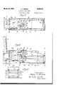
- a stove structur including a base 2, a lower portion or chamber member 3, an upper ⁇ portion or chamber member 4, a flue 5 and an intermediate partion 6, centrally apertured as at 1. It will be understood,'however, that the burners -may be used with a variety of stoves or heaters, the one illustrated herein being a practical example.
- a tank or storage zone for liquid fuel generally indicates a tank or storage zone for liquid fuel. It includes a bottom 9, a top I0,
- I2 is a lling neck normally closedy by Va removable cap I5.
- I6 is an air'inlet tube normally fixed upon the top member
- an inner tube I9 Radially within the tube I6 is an inner tube I9, which may be controlled by a handle 20 herein Ashown as resting upon the upper end of the tube I6, which serves as a positioning abutment.
- the inner tube I9 has a plurality of slots 2
- a further rotation of the inner tube in the direction of the arrow in Figure 5, can be employed partially or entirely to close the slot 22.
- the air supplied to the fuel in the tank 8 can be controlled manu- .ally from outside from substantially zero flow to apredetermined maximum.
- the proportions and shapes of the slots may be widely varied or other systems of apertures may be employed, but the structure shown herein has been proven efllclent in practice.
- a vapor outlet 25 Extending upwardly from the top Ill of the tank 8 is a vapor outlet 25 which terminates in a 40 horizontal portion 26, which in turn communicates with the interior of a pot generally indicated as ⁇ 2'
- the pot is provided with a plurality of air inlets 28 located atr various distances from the bottom "i" or end 29 of the pot.
- 30 is a baille centrally ap
- This aperture is preferably substantially larger in diameter than the diameter of the member 25 so that air can flow inwardly therethrough to supply the apertures 28 and 32.
- the wall H extends above the plane of the top il! of the4 tank and forms with an upturned flange Ilia of the tank top I 0, a space into which cooling water may be poured, if desired.
- combustion is initiatedin the container 8, which may for example be iilledfair- Lv full as shown in Figure 1.
- the handle 20 is' Lset to provide a sumcient supply vof air through the slots 2l and v22 to support combustion.
- the combustion taking place near the outlet A25 vaporizes a substantial quantity of the liquid fuel.
- 'I'he Iuel vaporized by the partial combustion maintained by the inowing air flows through the outlet25, .26 into the interior of the pot 21.
- There the vaporized fuel receives additional .air through the apertures 28.
- 'Ihese apertures provide primary air for the vaporized fuel.
- the primary mixture then flows ⁇ through the a'perture3l of baille plate 30 and'receives enough secondary air through the apertures 32 for complete combustion of the vaporized hydrocarbon.
- the flame in practice fiows through the inlet 35 into the lower stove chamber 3, through the aperture 1, and into the Vupper stove chamber I. It will be understood that the rate of combustion, :andthe amount of kfuel vaporized and burned, ⁇ iscontrolled by varying .the volume or rate of lflow of air admitted through the tubes I6 and i9 and the slots 2
- FIG. 6 .to -8 inclusive a similar generator type burner is illustrated. However the tank 50 is shown having afbottom llil, a top 52,
- An outer wall structure 55 is shown connected by spacing and heat exchange vanes 55, :the wall 55 being spaced'upwardly atits lower edge topermit a ow of air upwardly Abetweenthe walls 53 and 5I and the outer wall 55.
- the air which flows upwardly in thisfashion passes into a Space housed by .a top cover 51.
- the Vouter wall :55 lextends endwise beyond the fuel ⁇ tank and is secured to the .flame ring structure 58.
- the top cover 51 may be secured to the same flame ring structure. The bottom of the space thus defined is closed .by an additional wall 59.
- 51 isan inner air inlet tube corresponding to the tube i9, of Figure 1. It is provided-with slots 68 and '69 which may be identical with the slots 2
- the cup 65 may be employed to receive a priming volume of fuel.
- a priming volume of fuel When the priming charge is positioned and ignited, a. flow of air down through the tube draws the burning material down to the surface of the fuel in the tank. Ihe control of the air for the burner operates ⁇ :lust as in the case of Figures l and following, the
- Figures 6 and7 is particularly eflicient in that the tank is insulated from the burner by air intervals through which cooling air ⁇ flows on.its way to the space about the pot-21a.
- the inner air tube vlil or I9 rests by gravity in the position in which it is shown in the drawings, the handle serving-as the limit means. Not only is the inner tube readily rotatable in relation to the'outer, but it can readily be upwardly withdrawn ,by its handle as when the cup 65 is employed to receive'apri'ming charge.
- the priming charge is lighted and flows freely down through theouter tube and to the surface of the fuel inthe tank.
- an excess supply of vair is ad- 'vantageoua4 so the shuttering eiiect of the inner Vy structure, a fuel' storage and vaporizing tank pot will therefore not be further described.
- I illustrate a. T-member 60, a side branch 6l connected by a pipe 62 with the interior of the pot 21a. .63 illustrates a nut secured to the bottom 5l of the tank. Screw threaded into it is the bottom of the air ⁇ tube El.
- the top of this tube carries a cup 65 which may be welded thereto and which extends somewhat above ⁇ the top of the tube.
- the cup 65 is seated in the top of the T 60, which is counterbored to receive it.
- the cup serves as means to hold the T 60 rmly down against the top 52 of the tank.
- a hydroxylating burner pot having a closed en d and an open end and a circumferential. wall provided with a plurality of air'i'nlet apertures at various distances from its endsa flame ringpartially closing the openend and having a generally central aperture, a vapor duct extending fromfthe tank through the closed bottom ofv the' pot,j a heater, means for maintaining thefinteiiorl of the heater in communication with the interior of the pot, means i'ordelivering air tof the tank above the level of the fuel therein. at a variable rate of flow, for thereby controlling the rate of vaporlzing combustion in said tank and of combustion in said pot.
- a fuel storage and .vaporizing tank adapted to contain a substantialsupply of a liquid fuel
- a hydroxylating burner pot having a closed end and an open end and a circumferential wall provided with a plurality of ai'inlet apertures at various distances from its ends, afname ring partially closing the open end and having a generally central aperture, a vapor duct extending from the tank through the closed bottom of the pot, a heater, means for maintaining the interior of the heater in communication with the interior of the pot, means for delivering air to the tank above the level of the fuel therein, at a variable rate cf ilow,
- a fuel storage and vaporizing tank adapted to contain a substantial supply of a liquid fuel
- a hydroxylating burner pot having a closed end and an open end and a circumferential wall provided with a plurality of air inlet apertures at various distances from its ends, a name ring partially closing the open end and having a generally central aperture, a vapor duct extending from the tank through the closed bottom of the pot, a heater, means for maintaining the interior of the heater in communication with the interior of the pot, means for delivering air tothe tank above the level of the fuel therein, at a variable rate of flow, for thereby controlling the rate of vaporizing combustion in said tank, and of combustion in said pot, and means for directing additional air to the space about said pot, for passage through the air inlets of the pot Wall, including an air directing housing surrounding the tank, adapted to cool said tank and to protect it from the heat of combustion in the burner.
- a fuel storage and vaporizing tank adapted to contain a substantial supply of a liquid fuel
- a hydroxylating burner pot having a circum-- ferential generally cylindrical wall, with a hori zontal axis, and a closed end and an open end, said wall being provided with a plurality of air inlet apertures at various distances from its ends, a flame ring partially closing the open end, and having a generally central aperture, a duct extending from the tank through the closed bottom of the pot, a heater, means for maintaining the interior of the heater in communication with the interior of the pot, means for delivering air to the tank above the level of the fuel therein, at a variable ⁇ rate of flow and to thereby control the rate of vaporizing combustion in said tank.
- a fuel -storage and vaporizing tank adapted to contain a substantial supply of a liquid fuel
- a hydroxylating burner pot having a circumferential generally cylindrical wall, with a horizontal axis,i,and a closed end and an open end, said wall being provided With a plurality of air inlet apertures at various distances from its ends, a flame ring partially closing the open end, and having a generally central aperture, a vapor duct extending from the tank through the closed bottom of the pot, a heater, means for maintaining the interior of the heater in communication with the interior of the pot, means for delivering air to the tank above the level of the fuel therein at a variable rate of flow and to thereby control the rate of vaporizing combustion in said tank, and an air directing housing surrounding said tank and said pot, spaced outwardly from the walls of said tank and pot and provided with air inlets through which air may pass to the interior of the housing.
- a heater and burner structure adapted to contain a substantial supply of a liquid fuel
- a hydroxylating burner pot having a circumferential generally cylindrical wall, with a horizontal axis, and a closed end and an open end, said wall being provided witha plurality of air inlet apertures at various distances from its ends, a flame ring partially closing the open end, and having a generally central aperture, a vapor duct extending from the tank through the closed bottom of the pot, a heater, means for maintaining the interior of the heater in communication with the interior of the pot, means for delivering air to the tank above the level oi the fuel therein, at a variable rate of flow and to thereby control the rate of vaporizing combuspass to the interior of the housing, the means for delivering air to the tank and for varying the rate of flow of air to the tank extending outwardly through the wall of said air directing housing.
- a fuel storage and vaporizing tank adapted to contain a substantial supply of a liquid fuel
- a hydroxylating burner pot having a closed end and an open end, a circumferential Wall provided With a plurality of air inlet apertures at various distances from its ends, and a generally centrally apertured flame ⁇ ring partially closing the open end, said pot being horizontally axised and being spaced laterally from the tank, a vapor duct extending from the tank through the closed bottom of the pot, a heater, means for main- ⁇ taining the interior of the heater in communicaadapted to contain a substantial supply of a liquid fuel, a hydroxylating burner pot having a closed end and an open end, a circumferential 'Wall provided with a plurality of air inlet apertures at various distances from its ends, and a generally centrally apertured flame ring partially closing the open end, said pot being horizontally axised and being spaced laterally from. the tank, a
- a surrounding housing extending about the pot and the tank and spaced from the side walls of the tank, having air inlets about the bottom of the side walls of the tank adapted to permit a flow of air through the interior of said housing substantially throughout the periphery of the tank.
Landscapes
- Engineering & Computer Science (AREA)
- Chemical & Material Sciences (AREA)
- Combustion & Propulsion (AREA)
- Mechanical Engineering (AREA)
- General Engineering & Computer Science (AREA)
- Evaporation-Type Combustion Burners (AREA)
Description
Marel 19, 1946.
J. L. BREESE l 2,396,818
GENERATOR TYPE HEATER Filed July 2, 1943 3 Sheets-Sheet l /5 fad noooooo o oo o'oooo wg( E "W m f I I I I I I j vif/@far Jaweylfw@ I I y *u N differ/@yx J. L.. BREESE GENERATOR TYPE HEATER March 19, 1946.
Filed July 2, 1945 n 5 Sheets-$11661'l 2 2272/677507 7c-77365 Lreese March 19, 1946. J. L BREEsE GENERATOR TYPE HETER Filed July 2, 1943 3 Sheets-Sheet 5 Patented Mar.\1*9,1946
GENERATOR TYPE HEATER James L. Breese, Santa Fe, N. Mex., assigner to Oil Devices, Santa Fe, N. Mex., a limited partnership of Illinois l' Application July 2, 1943, Serial No. 493,251
8 Claims.
My-invention relates to an improvement in generator type heater and has for one purpose to provide a burner kwhich is light, simple andA eiiicient. n
Another purpose is'to provide a burner struc- "ture adaptedfor use in the eld, for example with military stoves.
Another purpose is to provide improvedmeans l for maintainingthe fuel supply cool.
Another purpose is to provide improved means -for insulating the fuel supply from an .adjacent tical section;
Figure 2 is a plan view with parts broken away; y
' Figure 3 is a section along the line 3-3 of Figure 1; v
Figure 4 is a section on an enlarged scale along the line 2 4 of Figure 1;
Figure 5 is a similar section illustrating the parts in a different position;
Figure 6 is a vertical section through a variant form ofthe device;
Figure '7 is a section along the line l--l of Figure 6; 1
Figure 8 isa section along the line 8-6 of Figure.
" Like partsVVV are indicated by like characters throughoutith'e specification and drawings.
Referring/first to Figures 1 to 5 of the drawings, I indicates any suitable supporting surface which, ,in the field, may be the ground.
Mounted-'upon the supporting surface is a stove structur including a base 2, a lower portion or chamber member 3, an upper `portion or chamber member 4, a flue 5 and an intermediate partion 6, centrally apertured as at 1. It will be understood,'however, that the burners -may be used with a variety of stoves or heaters, the one illustrated herein being a practical example.
8 generally indicates a tank or storage zone for liquid fuel. It includes a bottom 9, a top I0,
a circumferential generally cylindrical, inner wall I I, a circumferential outer wall I2, and a plurality of radial spacing partitions |3. It will be observeddthat the wall I2 terminates at its lower edge somewhat above the Wall Il in order to provide space for yair to pass upwardly through the passages between the adjacent radial partitions I3. These partitions may also serve as cooling fins. I4 is a lling neck normally closedy by Va removable cap I5. I6 is an air'inlet tube normally fixed upon the top member |0. It is shown fas extending'practically to the bottom of 5 the tank. It is provided with opposite air outlet slots I1 and I8, the slot I8 being of substan` tially greater width than the slot Il. are shown as extending below the level ofthe liquid so that kwithin the possible variations of 10 the liquid level, airwill always be able to pass out through the slots I'I or I8 at or adjacent the level of the liquid.
Radially within the tube I6 is an inner tube I9, which may be controlled by a handle 20 herein Ashown as resting upon the upper end of the tube I6, which serves as a positioning abutment. The inner tube I9 has a plurality of slots 2|, 22 which are herein shown as of about the same width. It will be observed that the effective cross sectional area for the admission of air can 'be varied by using the handle 20 to rotate the tube I9 in relation to the tube I6. In the position shown in Figure 4, the inner slots 2| and 22 are both unmasked. In the position of 25 Figure 5, the slot 2| has been masked but the slot 22 is still unmasked. A further rotation of the inner tube in the direction of the arrow in Figure 5, can be employed partially or entirely to close the slot 22. Thus the air supplied to the fuel in the tank 8 can be controlled manu- .ally from outside from substantially zero flow to apredetermined maximum. It will be understood, of course, that the proportions and shapes of the slots may be widely varied or other systems of apertures may be employed, but the structure shown herein has been proven efllclent in practice.
Extending upwardly from the top Ill of the tank 8 is a vapor outlet 25 which terminates in a 40 horizontal portion 26, which in turn communicates with the interior of a pot generally indicated as\2'| and herein shown as horizontally axised. The pot is provided with a plurality of air inlets 28 located atr various distances from the bottom "i" or end 29 of the pot. 30 is a baille centrally ap,
ertured as at 3|. Beyond the baille is shown a plurality ofy air inlets 32 of greater diameter and more closely spaced than the apertures or inlets 28. The top or end of the pot is closed by a` The slots-` I flame ring 33 with a central aperture 36 aligned".`
ing a bottom or end 4I provided with an aperture l2 through which the element 25 extends. This aperture is preferably substantially larger in diameter than the diameter of the member 25 so that air can flow inwardly therethrough to supply the apertures 28 and 32. i
It will be noted that the wall H extends above the plane of the top il! of the4 tank and forms with an upturned flange Ilia of the tank top I 0, a space into which cooling water may be poured, if desired.
In the operation .of a generator burner of the type herein shown, combustion is initiatedin the container 8, which may for example be iilledfair- Lv full as shown in Figure 1. The handle 20 is' Lset to provide a sumcient supply vof air through the slots 2l and v22 to support combustion. The combustion taking place near the outlet A25 vaporizes a substantial quantity of the liquid fuel. 'I'he Iuel vaporized by the partial combustion maintained by the inowing air flows through the outlet25, .26 into the interior of the pot 21. There the vaporized fuel receives additional .air through the apertures 28. 'Ihese apertures provide primary air for the vaporized fuel. The primary mixture then flows `through the a'perture3l of baille plate 30 and'receives enough secondary air through the apertures 32 for complete combustion of the vaporized hydrocarbon. The flame in practice fiows through the inlet 35 into the lower stove chamber 3, through the aperture 1, and into the Vupper stove chamber I. It will be understood that the rate of combustion, :andthe amount of kfuel vaporized and burned,`iscontrolled by varying .the volume or rate of lflow of air admitted through the tubes I6 and i9 and the slots 2| and 22.
Referring to Figures 6 .to -8 inclusive, a similar generator type burner is illustrated. However the tank 50 is shown having afbottom llil, a top 52,
end portions or walls'53 vand side walls 54. An outer wall structure 55 is shown connected by spacing and heat exchange vanes 55, :the wall 55 being spaced'upwardly atits lower edge topermit a ow of air upwardly Abetweenthe walls 53 and 5I and the outer wall 55. The air which flows upwardly in thisfashion passes into a Space housed by .a top cover 51. It will be observed that the Vouter wall :55 lextends endwise beyond the fuel `tank and is secured to the .flame ring structure 58. The top cover 51 may be secured to the same flame ring structure. The bottom of the space thus defined is closed .by an additional wall 59. Thus the air which passes upwardly about the tank to cool it is in communication with the space about the potlla, as shown in Figures 6 and '7 and may pass through the apertures 28a and 32a of that pot. It willbevunderstood that asoasis tube 64 is provided with air inlet slots B8, Ita, which may be identical with the slots Vl 1 and IB.
51 isan inner air inlet tube corresponding to the tube i9, of Figure 1. It is provided-with slots 68 and '69 which may be identical with the slots 2| and 22 of Figures 4 and 5. It may also be provided with a handle 10.
In the operation ofthe device as shown in Figures 6 and '7, the cup 65 may be employed to receive a priming volume of fuel. When the priming charge is positioned and ignited, a. flow of air down through the tube draws the burning material down to the surface of the fuel in the tank. Ihe control of the air for the burner operates `:lust as in the case of Figures l and following, the
volume or rate of fiow of air being yemployed to control `the rate of vaporlzaticnand' rate of combustion.
The form of Figures 6 and7 is particularly eflicient in that the tank is insulated from the burner by air intervals through which cooling air `flows on.its way to the space about the pot-21a.
It will be understood also that the air admission and lighting equipment shownin Figuresv and 7 may be employed equally well ,with the form of Figures 1 and following.
It will be understood that the inner air tube vlil or I9 rests by gravity in the position in which it is shown in the drawings, the handle serving-as the limit means. Not only is the inner tube readily rotatable in relation to the'outer, but it can readily be upwardly withdrawn ,by its handle as when the cup 65 is employed to receive'apri'ming charge. At the starting stage, the priming charge is lighted and flows freely down through theouter tube and to the surface of the fuel inthe tank. At the starting stage, an excess supply of vair is ad- 'vantageoua4 so the shuttering eiiect of the inner Vy structure, a fuel' storage and vaporizing tank pot will therefore not be further described.
In. order to deliver the products of combustion and the vaporized fuel from the tank to the pot, I illustrate a. T-member 60, a side branch 6l connected by a pipe 62 with the interior of the pot 21a. .63 illustrates a nut secured to the bottom 5l of the tank. Screw threaded into it is the bottom of the air `tube El. The top of this tube carries a cup 65 which may be welded thereto and which extends somewhat above `the top of the tube. The cup 65 is seated in the top of the T 60, which is counterbored to receive it. The cup serves as means to hold the T 60 rmly down against the top 52 of the tank. It will be observed that the adapted to contain a substantial supply of a liquid fuel, a hydroxylating burner pot having a closed en d and an open end and a circumferential. wall provided with a plurality of air'i'nlet apertures at various distances from its endsa flame ringpartially closing the openend and having a generally central aperture, a vapor duct extending fromfthe tank through the closed bottom ofv the' pot,j a heater, means for maintaining thefinteiiorl of the heater in communication with the interior of the pot, means i'ordelivering air tof the tank above the level of the fuel therein. at a variable rate of flow, for thereby controlling the rate of vaporlzing combustion in said tank and of combustion in said pot.
2. In combination, in va heater and burner structure, a fuel storage and .vaporizing tank adapted to contain a substantialsupply of a liquid fuel, a hydroxylating burner pot 'having a closed end and an open end and a circumferential wall provided with a plurality of ai'inlet apertures at various distances from its ends, afname ring partially closing the open end and having a generally central aperture, a vapor duct extending from the tank through the closed bottom of the pot, a heater, means for maintaining the interior of the heater in communication with the interior of the pot, means for delivering air to the tank above the level of the fuel therein, at a variable rate cf ilow,
for thereby controlling the rate of vaporizing combustion in said tank, and of combustion insaid pot, and means for directing additional air to the space about said pot, for passage through the air inlets of the pot Wall.
3. In combination, in a heater and burner structure, a fuel storage and vaporizing tank adapted to contain a substantial supply of a liquid fuel, a hydroxylating burner pot having a closed end and an open end and a circumferential wall provided with a plurality of air inlet apertures at various distances from its ends, a name ring partially closing the open end and having a generally central aperture, a vapor duct extending from the tank through the closed bottom of the pot, a heater, means for maintaining the interior of the heater in communication with the interior of the pot, means for delivering air tothe tank above the level of the fuel therein, at a variable rate of flow, for thereby controlling the rate of vaporizing combustion in said tank, and of combustion in said pot, and means for directing additional air to the space about said pot, for passage through the air inlets of the pot Wall, including an air directing housing surrounding the tank, adapted to cool said tank and to protect it from the heat of combustion in the burner.
4. In combination, in a heater and burner structure, a fuel storage and vaporizing tank adapted to contain a substantial supply of a liquid fuel, a hydroxylating burner pot having a circum-- ferential generally cylindrical wall, with a hori zontal axis, and a closed end and an open end, said wall being provided with a plurality of air inlet apertures at various distances from its ends, a flame ring partially closing the open end, and having a generally central aperture, a duct extending from the tank through the closed bottom of the pot, a heater, means for maintaining the interior of the heater in communication with the interior of the pot, means for delivering air to the tank above the level of the fuel therein, at a variable `rate of flow and to thereby control the rate of vaporizing combustion in said tank.
5. In combination, in a heater vand burner structure, a fuel -storage and vaporizing tank adapted to contain a substantial supply of a liquid fuel, a hydroxylating burner pot having a circumferential generally cylindrical wall, with a horizontal axis,i,and a closed end and an open end, said wall being provided With a plurality of air inlet apertures at various distances from its ends, a flame ring partially closing the open end, and having a generally central aperture, a vapor duct extending from the tank through the closed bottom of the pot, a heater, means for maintaining the interior of the heater in communication with the interior of the pot, means for delivering air to the tank above the level of the fuel therein at a variable rate of flow and to thereby control the rate of vaporizing combustion in said tank, and an air directing housing surrounding said tank and said pot, spaced outwardly from the walls of said tank and pot and provided with air inlets through which air may pass to the interior of the housing.
6. In combination, 'in a heater and burner structure. a fuel storage and vaporizing tank adapted to contain a substantial supply of a liquid fuel, a hydroxylating burner pot having a circumferential generally cylindrical wall, with a horizontal axis, and a closed end and an open end, said wall being provided witha plurality of air inlet apertures at various distances from its ends, a flame ring partially closing the open end, and having a generally central aperture, a vapor duct extending from the tank through the closed bottom of the pot, a heater, means for maintaining the interior of the heater in communication with the interior of the pot, means for delivering air to the tank above the level oi the fuel therein, at a variable rate of flow and to thereby control the rate of vaporizing combuspass to the interior of the housing, the means for delivering air to the tank and for varying the rate of flow of air to the tank extending outwardly through the wall of said air directing housing.
7. In combination, in a heater and burner structure, a fuel storage and vaporizing tank adapted to contain a substantial supply of a liquid fuel, a hydroxylating burner pot having a closed end and an open end, a circumferential Wall provided With a plurality of air inlet apertures at various distances from its ends, and a generally centrally apertured flame `ring partially closing the open end, said pot being horizontally axised and being spaced laterally from the tank, a vapor duct extending from the tank through the closed bottom of the pot, a heater, means for main- `taining the interior of the heater in communicaadapted to contain a substantial supply of a liquid fuel, a hydroxylating burner pot having a closed end and an open end, a circumferential 'Wall provided with a plurality of air inlet apertures at various distances from its ends, and a generally centrally apertured flame ring partially closing the open end, said pot being horizontally axised and being spaced laterally from. the tank, a vapor duct extending from the tank through the closed bottom of the pot, a heater, means for maintaining the interior of the heater in communication with the interior of the pot,
positioned laterally of the pot beyond the open end of the pot, means for delivering a varying rate of flow of air to the tank, and to thereby control the rate of vaporizing combustion in said tank and of combustion in said pot, and a surrounding housing extending about the pot and the tank and spaced from the side walls of the tank, having air inlets about the bottom of the side walls of the tank adapted to permit a flow of air through the interior of said housing substantially throughout the periphery of the tank.
JAMES L. BREESE.
Priority Applications (1)
| Application Number | Priority Date | Filing Date | Title |
|---|---|---|---|
| US493251A US2396818A (en) | 1943-07-02 | 1943-07-02 | Generator type heater |
Applications Claiming Priority (1)
| Application Number | Priority Date | Filing Date | Title |
|---|---|---|---|
| US493251A US2396818A (en) | 1943-07-02 | 1943-07-02 | Generator type heater |
Publications (1)
| Publication Number | Publication Date |
|---|---|
| US2396818A true US2396818A (en) | 1946-03-19 |
Family
ID=23959483
Family Applications (1)
| Application Number | Title | Priority Date | Filing Date |
|---|---|---|---|
| US493251A Expired - Lifetime US2396818A (en) | 1943-07-02 | 1943-07-02 | Generator type heater |
Country Status (1)
| Country | Link |
|---|---|
| US (1) | US2396818A (en) |
Cited By (3)
| Publication number | Priority date | Publication date | Assignee | Title |
|---|---|---|---|---|
| US2543980A (en) * | 1947-02-15 | 1951-03-06 | Motor Wheel Corp | Vaporizing type liquid fuel burner |
| US2553304A (en) * | 1948-04-26 | 1951-05-15 | Herbert F Daniels | Vaporizing type oil burner |
| US2587361A (en) * | 1947-08-15 | 1952-02-26 | Kresky Mfg Co Inc | Horizontal tray type oil burner |
-
1943
- 1943-07-02 US US493251A patent/US2396818A/en not_active Expired - Lifetime
Cited By (3)
| Publication number | Priority date | Publication date | Assignee | Title |
|---|---|---|---|---|
| US2543980A (en) * | 1947-02-15 | 1951-03-06 | Motor Wheel Corp | Vaporizing type liquid fuel burner |
| US2587361A (en) * | 1947-08-15 | 1952-02-26 | Kresky Mfg Co Inc | Horizontal tray type oil burner |
| US2553304A (en) * | 1948-04-26 | 1951-05-15 | Herbert F Daniels | Vaporizing type oil burner |
Similar Documents
| Publication | Publication Date | Title |
|---|---|---|
| US2396818A (en) | Generator type heater | |
| US2460013A (en) | Quadrant pilot for pot type oil burners | |
| US2262922A (en) | Oil burning heater | |
| US2393233A (en) | Oil burner with vaporizing type pilot | |
| US2418709A (en) | Inverted pot type burner | |
| US2361912A (en) | Notched pilot baffle | |
| US2179142A (en) | Hydrocarbon burner | |
| US2396675A (en) | Liquid fuel burner | |
| US1707774A (en) | Rotary oil or hydrocarbon burner | |
| US2067666A (en) | Liquid fuel burner | |
| US2386556A (en) | Horizontal pot type burner | |
| US2228324A (en) | Hydrocarbon fuel burner | |
| US2224089A (en) | Oil burner | |
| US2346781A (en) | Pot-type burner with hollow pilot | |
| US2396821A (en) | Liquid fuel burner structure | |
| US1639518A (en) | Burner | |
| US1990962A (en) | Gas burner | |
| US2124169A (en) | Oil burner | |
| US1693054A (en) | Hydrocarbon burner | |
| US1597027A (en) | Oil burner | |
| US2410478A (en) | Generator type burner | |
| US2355418A (en) | Two-level liquid fuel burner | |
| US2353439A (en) | Pilot support and air feed for pot type burners | |
| US2475024A (en) | Semicylindrical pot-type burner | |
| US2029184A (en) | Oil burning apparatus |