US2315984A - Temperature regulator - Google Patents
Temperature regulator Download PDFInfo
- Publication number
- US2315984A US2315984A US314848A US31484840A US2315984A US 2315984 A US2315984 A US 2315984A US 314848 A US314848 A US 314848A US 31484840 A US31484840 A US 31484840A US 2315984 A US2315984 A US 2315984A
- Authority
- US
- United States
- Prior art keywords
- thermostat
- temperature
- boiler
- heating
- coil
- Prior art date
- Legal status (The legal status is an assumption and is not a legal conclusion. Google has not performed a legal analysis and makes no representation as to the accuracy of the status listed.)
- Expired - Lifetime
Links
- 238000010438 heat treatment Methods 0.000 description 19
- XLYOFNOQVPJJNP-UHFFFAOYSA-N water Substances O XLYOFNOQVPJJNP-UHFFFAOYSA-N 0.000 description 12
- 230000001276 controlling effect Effects 0.000 description 5
- 238000002485 combustion reaction Methods 0.000 description 4
- 230000001105 regulatory effect Effects 0.000 description 3
- XEEYBQQBJWHFJM-UHFFFAOYSA-N Iron Chemical group [Fe] XEEYBQQBJWHFJM-UHFFFAOYSA-N 0.000 description 2
- 239000007788 liquid Substances 0.000 description 2
- 230000005540 biological transmission Effects 0.000 description 1
- 230000000694 effects Effects 0.000 description 1
- 238000005485 electric heating Methods 0.000 description 1
- 238000003780 insertion Methods 0.000 description 1
- 230000037431 insertion Effects 0.000 description 1
- 238000009434 installation Methods 0.000 description 1
- 238000012423 maintenance Methods 0.000 description 1
- 238000000034 method Methods 0.000 description 1
- 238000004804 winding Methods 0.000 description 1
Images


Classifications
-
- H—ELECTRICITY
- H05—ELECTRIC TECHNIQUES NOT OTHERWISE PROVIDED FOR
- H05B—ELECTRIC HEATING; ELECTRIC LIGHT SOURCES NOT OTHERWISE PROVIDED FOR; CIRCUIT ARRANGEMENTS FOR ELECTRIC LIGHT SOURCES, IN GENERAL
- H05B1/00—Details of electric heating devices
- H05B1/02—Automatic switching arrangements specially adapted to apparatus ; Control of heating devices
- H05B1/0227—Applications
- H05B1/0252—Domestic applications
- H05B1/0275—Heating of spaces, e.g. rooms, wardrobes
- H05B1/0283—For heating of fluids, e.g. water heaters
-
- F—MECHANICAL ENGINEERING; LIGHTING; HEATING; WEAPONS; BLASTING
- F24—HEATING; RANGES; VENTILATING
- F24D—DOMESTIC- OR SPACE-HEATING SYSTEMS, e.g. CENTRAL HEATING SYSTEMS; DOMESTIC HOT-WATER SUPPLY SYSTEMS; ELEMENTS OR COMPONENTS THEREFOR
- F24D19/00—Details
- F24D19/10—Arrangement or mounting of control or safety devices
- F24D19/1006—Arrangement or mounting of control or safety devices for water heating systems
- F24D19/1009—Arrangement or mounting of control or safety devices for water heating systems for central heating
-
- G—PHYSICS
- G05—CONTROLLING; REGULATING
- G05D—SYSTEMS FOR CONTROLLING OR REGULATING NON-ELECTRIC VARIABLES
- G05D23/00—Control of temperature
- G05D23/19—Control of temperature characterised by the use of electric means
- G05D23/1927—Control of temperature characterised by the use of electric means using a plurality of sensors
- G05D23/193—Control of temperature characterised by the use of electric means using a plurality of sensors sensing the temperaure in different places in thermal relationship with one or more spaces
- G05D23/1931—Control of temperature characterised by the use of electric means using a plurality of sensors sensing the temperaure in different places in thermal relationship with one or more spaces to control the temperature of one space
-
- G—PHYSICS
- G05—CONTROLLING; REGULATING
- G05D—SYSTEMS FOR CONTROLLING OR REGULATING NON-ELECTRIC VARIABLES
- G05D23/00—Control of temperature
- G05D23/19—Control of temperature characterised by the use of electric means
- G05D23/275—Control of temperature characterised by the use of electric means with sensing element expanding, contracting, or fusing in response to changes of temperature
- G05D23/27535—Details of the sensing element
- G05D23/27541—Details of the sensing element using expansible solid
Definitions
- thermostat in the heater, boiler or other heat distributing device such as will turn on or off or regulate the combustion means which is the primary source of the heat.
- a thermostat is normally provided with a lever for adjustment to allow the temperature of operation to be selected. It has been proposed in such a thermostat to obtain the equivalent of changing the thermostat setting by providing the thermostat with an electrical resistance element toprovide an auxiliary source of h at in addition to the heat derived from the heater which it is controlling so that such resistance element may supply-a continually varying quantity of heat to the thermostat by the intermittent switching on and off of.
- the switching cycle being controlled in an inverse ratio to the outside temperature.
- thermostat responsive to changes of the outside temperature, though protected from the sunlight or moisture conditions, and adapted to move a contact arm over a series of contacts controlling the supply of heating current to a second thermostat located in the room the temperature of which is to be controlled sothat the said room thermostat will operate at lower or higher room temperature to cut off the sup'plytof heat to the room.
- the temperatureora heating medium is varied'consequent on variation of weather conditions by electrical means such as a rheostat, a variable choke coil, or a variable ratio transformer, such electrical means being operated by a thermally sensitive member exposed to the weather conditions, the electrical means being arranged to regulate continuously an auxiliary supply of heat to a thermostat controlling the boiler temperature.
- electrical means such as a rheostat, a variable choke coil, or a variable ratio transformer, such electrical means being operated by a thermally sensitive member exposed to the weather conditions, the electrical means being arranged to regulate continuously an auxiliary supply of heat to a thermostat controlling the boiler temperature.
- This latter thermostat may be of the type in which the movement of the thermally sensitive element operates a switch to turn oil or on or regulate the heating means, or the thermostat may be of the type in which the expansion means, usually comprising a dilatable vessel filled with a liquid is mechanically coupled to a damper or dampers adapted to be moved to shut, open or to intermediate positions withina certain number of temperature degrees changeso as to control the boiler water temperature to a substantially constant valu within the limits or change necessary to move the damper or dampers.
- the thermostat exposed to weather conditions is mounted in a heated container the temperature of which is governed by the weather conditions.
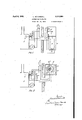
- l denotes the boiler or heater which is the source of supply of heat or the" heating medium to the enclosed space
- whi1e2 denotes the thermostat in the boiler controlling the water temperature.
- a heating resistance 3 surrounds a part of the thermal element of the boiler thermostat 2 so as to affect the thermostat conjointly with the boiler water temper-' ature.
- a rheostat 4 which is sup.
- thermo- denotes a thermostat located in the outside atmosphere preferably in a container 1.
- thethermostat 6 serves to operate a contact 6' on the rheostat hand in Fig. 2 the thermo-.
- stat 6" operates the contact 6" on the rheostat 4.
- a resistance l l is arranged to take a small fixed amount of energy from the supply 5 and is disposed within the container 1 so as to maintain the container 7 at a temperature above that of the outside atmosphere.
- the thermostat 2 may control the water temperature in the arrangement of Figs. 1, 2, 4 and 5 by switching on or off the switch 2' to regulate the combustion means 8, or in the arrangement of Fig. 3 the thermostat 2 may actuate the lever 2
- thermostat 2 be arranged to control the boiler l at a temperature ofsay Ffadditional heating of the thermostat 2, as'a result of a current passing around the auxiliary resistance coil 3, will regulate the combustion means 8 or the damper 8a to reduce the rate of temperature.
- 'sistance II is arranged to take a constant load combustion and therefore to lower the water If the current passing in coil 3 be increased then still further-.reduction of boiler water temperature will result;
- the operation as described is brought about by the thermostat 6 exposed to the outside temperature moving in accordance with change in temperature and so altering the continually variable rheostat 4, and in the manner explained, changing the temperature of the boiler water in an inverse ratio to the outside temperature.
- the container 1 be subject to wind or rain the heat loss from the container 1 will be greater and the internal temperature lower than it would be with the same external temperature without wind or rain.
- Such variation of weather conditions will, of course, affect the heat loss from a building in a similar manner, and therefore the position of the contacts 6' and 6" on the rheostat 4 will enable continuous adjustment to be made automatically to the boiler water temperature to compensate for the variation of losses from the building with changing weather conditions.
- the temperature inside the heated container I may bear a' true relation to weather conditions it is necessary that the electrical input be maintained substantially constant. Two methods of accomplishing this are In Figs.
- Fig. 3 much of the electrical heating supplied by the coil 3 would be lost to the body of the boiler by conduction through the thermostat 2.
- the electrical heater would therefore preferably be applied to a separate vessel in hydraulic connection with the boiler control thermostat 2 or a separate dilatable vessel, filled with a liquid and fitted with an electric heating winding, may be connected in mechanical series with the transmission between the thermos at 2 and the damper or air inlet door 8a. 1
- Figs. 4 and 5 are utilised foralternating current circuits.
- the rheostat 4 shown in Figs. 1 and 3 is replaced by a choke coil I2 which is supplied with current from a suitable source 5.
- the thermostat 6 is located in the outside atmosphere preferably in a container 1 and serves to operate through a lever arm 20 the movable iron core I3 of the choke coil I2 which is connected in series with the heating resistance 3 for supplying additional heat to the boiler thermostat 2.
- the simple chok coil I2 shown in Fig, 4 is replaced by a transformer I4 in which coil I 5 is energised fromthe alternating current supply 5 and coil I6 carried on a movable bar I! moved by the thermally sensitive member 6.
- the electric heater 3 surrounding the stem of the boiler thermostat 2. is connected across the movable coil I6 and receives its supply from it.
- the rheostat 4 of Figs. 1, 2, and 3, the choke coil I2 of Fig; 4 andv the transformer of Fig. 5 comprise controllers for varying the heating of the resistance 3.
- the voltage applied to the electric heater 3 on the boiler control thermostat is made to vary by an amount which is proportional to the outside weather variation taking into account the effect of sunshine, rain or windage losses.
- An electric indicator [8 may as shown be connected across the heater and arranged to give readings, the numerical value of which will be proportional to the effective outside temperature.
- Apparatus for varying the temperature of a heating medium consequent on variation of weather conditions comprising a thermostat sensitive to and controlling the temperature of the heating medium, an auxiliary electric heat- LEONARD SATCHWELII- I
Landscapes
- Engineering & Computer Science (AREA)
- Physics & Mathematics (AREA)
- General Physics & Mathematics (AREA)
- Automation & Control Theory (AREA)
- Chemical & Material Sciences (AREA)
- Thermal Sciences (AREA)
- Remote Sensing (AREA)
- Combustion & Propulsion (AREA)
- Mechanical Engineering (AREA)
- General Engineering & Computer Science (AREA)
- Regulation And Control Of Combustion (AREA)
- Control Of Combustion (AREA)
- Air Supply (AREA)
- Control Of Resistance Heating (AREA)
- Steam Or Hot-Water Central Heating Systems (AREA)
Description
April 6, 1943.
L. SATCHWELL TEMPERATURE REGULATOR Filed Jan. 20, 1940 3 Sheets-Sheet 1 April 6, 1943. SATCHWEL'L 2,315,984
' TEMPERATURE REGULATOR Filed Jan. 20, 19.40 3 Sheet-Sheet 2 April 6, 1943.
L. SATCHWELL TEMPERATURE REGULATOR s Shee ts-Sheet 5 Filed Jan. 20, 1940 Patented Ap 6, 19 43 UNITED STATES PATENT" FF 'remeae'ruannwm'ron Leonard Satchweil, Slough, England Application January 20, 1940, Serial No. 314,84
In Great Britain January 31, 1939 1 Claim.
peratureof the water circulated be regulated to be a high when outside temperature i low and vice versa, then compensation for variation of heat loss will be obtained, resulting, if the compensation be correctly proportioned, in the maintenance of steady temperature in the room.
In a controlled heating installation it is usual to provide a thermostat in the heater, boiler or other heat distributing device such as will turn on or off or regulate the combustion means which is the primary source of the heat. Such a thermostat is normally provided with a lever for adjustment to allow the temperature of operation to be selected. It has been proposed in such a thermostat to obtain the equivalent of changing the thermostat setting by providing the thermostat with an electrical resistance element toprovide an auxiliary source of h at in addition to the heat derived from the heater which it is controlling so that such resistance element may supply-a continually varying quantity of heat to the thermostat by the intermittent switching on and off of. a
fixed amount of energy, the switching cycle being controlled in an inverse ratio to the outside temperature.
It has also been proposed to provide in a ter-- perature control system a thermostat responsive to changes of the outside temperature, though protected from the sunlight or moisture conditions, and adapted to move a contact arm over a series of contacts controlling the supply of heating current to a second thermostat located in the room the temperature of which is to be controlled sothat the said room thermostat will operate at lower or higher room temperature to cut off the sup'plytof heat to the room.
Itz -has further been proposed in central heating plants. to control the boiler temperature in relationtti'the outside temperature by regulating the size 'of the-flame by the insertion of regulating resistances in-the circuit of the motor driving the oil'pump' and" air blower by means of an outside thermostat.
In accordance with the present invention the temperatureora heating medium is varied'consequent on variation of weather conditions by electrical means such as a rheostat, a variable choke coil, or a variable ratio transformer, such electrical means being operated by a thermally sensitive member exposed to the weather conditions, the electrical means being arranged to regulate continuously an auxiliary supply of heat to a thermostat controlling the boiler temperature.
This latter thermostat may be of the type in which the movement of the thermally sensitive element operates a switch to turn oil or on or regulate the heating means, or the thermostat may be of the type in which the expansion means, usually comprising a dilatable vessel filled with a liquid is mechanically coupled to a damper or dampers adapted to be moved to shut, open or to intermediate positions withina certain number of temperature degrees changeso as to control the boiler water temperature to a substantially constant valu within the limits or change necessary to move the damper or dampers.-
' Suitably, the thermostat exposed to weather conditions is mounted in a heated container the temperature of which is governed by the weather conditions.
Several embodiments of the present invention.
are illustrated diagrammatically by way of example in Figs. Ito 5 of the accompanying drawings.
Referring to the drawings, l denotes the boiler or heater which is the source of supply of heat or the" heating medium to the enclosed space, whi1e2 denotes the thermostat in the boiler controlling the water temperature. A heating resistance 3 surrounds a part of the thermal element of the boiler thermostat 2 so as to affect the thermostat conjointly with the boiler water temper-' ature. InFigs. 1 to 3 of the drawingstheresistance 3 is controlled by a rheostat 4 which is sup.
' plied with current from a suitable source 5. 6
denotes a thermostat located in the outside atmosphere preferably in a container 1. In Figs. 1 and 3 thethermostat 6 serves to operate a contact 6' on the rheostat hand in Fig. 2 the thermo-.
The thermostat 2 may control the water temperature in the arrangement of Figs. 1, 2, 4 and 5 by switching on or off the switch 2' to regulate the combustion means 8, or in the arrangement of Fig. 3 the thermostat 2 may actuate the lever 2| and. rods 22 to regulate the damper 8a and control the supply of air to the'fumace. I
If the thermostat 2 be arranged to control the boiler l at a temperature ofsay Ffadditional heating of the thermostat 2, as'a result of a current passing around the auxiliary resistance coil 3, will regulate the combustion means 8 or the damper 8a to reduce the rate of temperature.
shown in the drawings.
'sistance II is arranged to take a constant load combustion and therefore to lower the water If the current passing in coil 3 be increased then still further-.reduction of boiler water temperature will result; The operation as described is brought about by the thermostat 6 exposed to the outside temperature moving in accordance with change in temperature and so altering the continually variable rheostat 4, and in the manner explained, changing the temperature of the boiler water in an inverse ratio to the outside temperature.
If the container 1 be subject to wind or rain the heat loss from the container 1 will be greater and the internal temperature lower than it would be with the same external temperature without wind or rain. Such variation of weather conditions will, of course, affect the heat loss from a building in a similar manner, and therefore the position of the contacts 6' and 6" on the rheostat 4 will enable continuous adjustment to be made automatically to the boiler water temperature to compensate for the variation of losses from the building with changing weather conditions. In order that the temperature inside the heated container I may bear a' true relation to weather conditions it is necessary that the electrical input be maintained substantially constant. Two methods of accomplishing this are In Figs. 1 and 3 a refrom the supply and the thermal element container I is separated from a container in which the rheostat 4 is mounted so that the variation 01' watts in the rheostat consequent on movement 'the' circuit .of the rheostat 4 and boiler thermostat heating resistance 3, connected so that variation of heating energy in the rheostat 4, consequenton movement of the thermostat 6, is compensated for by the change of energy in the resistance 9 so as. to maintain the total heating energy in the container 1 practically constant, thus simplifying the arrangement of thermostat and rheostat.
In Fig. 3 much of the electrical heating supplied by the coil 3 would be lost to the body of the boiler by conduction through the thermostat 2. The electrical heater would therefore preferably be applied to a separate vessel in hydraulic connection with the boiler control thermostat 2 or a separate dilatable vessel, filled with a liquid and fitted with an electric heating winding, may be connected in mechanical series with the transmission between the thermos at 2 and the damper or air inlet door 8a. 1
The embodiments shown in Figs. 4 and 5 are utilised foralternating current circuits. In Fig. 4 the rheostat 4 shown in Figs. 1 and 3 is replaced by a choke coil I2 which is supplied with current from a suitable source 5. The thermostat 6 is located in the outside atmosphere preferably in a container 1 and serves to operate through a lever arm 20 the movable iron core I3 of the choke coil I2 which is connected in series with the heating resistance 3 for supplying additional heat to the boiler thermostat 2.
Inoperation of the apparatus as the outside temperature falls the thermal expansion member 6 will contract, drawing the iron core I3 into the coil. This action by increasing the impedance of the circuit 5, 3, I2 will reduce the current flowing in it. Thi reduction of heating current in the heating coil 3 will necessitate a higher water temperature in the boiler surrounding the thermostat to bring it to the operating point.
A fall of outside temperature will therefore by the action of the thermally sensitive member exposed to weather conditions and working in conjunction with the boiler thermostat be accompanied by an increase of boiler water temperature.
In the arrangement shown in Fig. 5 the simple chok coil I2 shown in Fig, 4 is replaced by a transformer I4 in which coil I 5 is energised fromthe alternating current supply 5 and coil I6 carried on a movable bar I! moved by the thermally sensitive member 6. The electric heater 3 surrounding the stem of the boiler thermostat 2. is connected across the movable coil I6 and receives its supply from it.
As the outsid temperature falls the thermally sensitive member 6 contracts and operates lever I1 separating coil I6 from the energised coil I5 and thus reducing the voltage induced in coil I6 and therefore reducing the additional heating I applied to the boiler thermostat 2 by the coil This reduction of electric heat applied to the boiler thermostat in turn requires an increase of boiler water temperature to operate-the boiler thermostat.
The rheostat 4 of Figs. 1, 2, and 3, the choke coil I2 of Fig; 4 andv the transformer of Fig. 5 comprise controllers for varying the heating of the resistance 3.
It will be seen that in this invention as described in the foregoing description of the various embodiments the voltage applied to the electric heater 3 on the boiler control thermostat is made to vary by an amount which is proportional to the outside weather variation taking into account the effect of sunshine, rain or windage losses.
An electric indicator [8 may as shown be connected across the heater and arranged to give readings, the numerical value of which will be proportional to the effective outside temperature.
It is to be understood that the invention is not limited to the forms of the thermostat shown.
Neither is the invention limited to the arrangements of the resistances indicated.
I. claim:
Apparatus for varying the temperature of a heating medium consequent on variation of weather conditions comprising a thermostat sensitive to and controlling the temperature of the heating medium, an auxiliary electric heat- LEONARD SATCHWELII- I
Applications Claiming Priority (7)
| Application Number | Priority Date | Filing Date | Title |
|---|---|---|---|
| GB310139X | 1939-01-31 | ||
| GB94219X | 1939-01-31 | ||
| GB2315984X | 1939-01-31 | ||
| GB857888X | 1939-01-31 | ||
| GB3324/39A GB525821A (en) | 1939-01-31 | 1939-01-31 | Improvements in or relating to temperature regulators |
| GB12900/39A GB529170A (en) | 1939-01-31 | 1939-04-29 | Improvements in and relating to temperature regulators |
| GB290439X | 1939-04-29 |
Publications (1)
| Publication Number | Publication Date |
|---|---|
| US2315984A true US2315984A (en) | 1943-04-06 |
Family
ID=62200164
Family Applications (1)
| Application Number | Title | Priority Date | Filing Date |
|---|---|---|---|
| US314848A Expired - Lifetime US2315984A (en) | 1939-01-31 | 1940-01-20 | Temperature regulator |
Country Status (5)
| Country | Link |
|---|---|
| US (1) | US2315984A (en) |
| CH (1) | CH226191A (en) |
| FR (1) | FR857888A (en) |
| GB (2) | GB525821A (en) |
| NL (1) | NL60536C (en) |
Cited By (2)
| Publication number | Priority date | Publication date | Assignee | Title |
|---|---|---|---|---|
| US2553060A (en) * | 1946-04-06 | 1951-05-15 | Trane Co | Heating control system |
| US3130354A (en) * | 1959-02-20 | 1964-04-21 | Herbert S Burling | Temperature control |
-
1939
- 1939-01-31 GB GB3324/39A patent/GB525821A/en not_active Expired
- 1939-04-29 GB GB12900/39A patent/GB529170A/en not_active Expired
- 1939-07-07 NL NL94219A patent/NL60536C/en active
- 1939-07-13 FR FR857888D patent/FR857888A/en not_active Expired
- 1939-07-14 CH CH226191D patent/CH226191A/en unknown
-
1940
- 1940-01-20 US US314848A patent/US2315984A/en not_active Expired - Lifetime
Cited By (2)
| Publication number | Priority date | Publication date | Assignee | Title |
|---|---|---|---|---|
| US2553060A (en) * | 1946-04-06 | 1951-05-15 | Trane Co | Heating control system |
| US3130354A (en) * | 1959-02-20 | 1964-04-21 | Herbert S Burling | Temperature control |
Also Published As
| Publication number | Publication date |
|---|---|
| FR857888A (en) | 1940-10-03 |
| GB529170A (en) | 1940-11-15 |
| GB525821A (en) | 1940-09-05 |
| CH226191A (en) | 1943-03-31 |
| NL60536C (en) | 1948-02-16 |
Similar Documents
| Publication | Publication Date | Title |
|---|---|---|
| US2819371A (en) | Heating apparatus | |
| US2063613A (en) | Heat regulation for buildings | |
| US2425998A (en) | Thermostat control mechanism for heating systems | |
| US2564120A (en) | Temperature control with lag compensation | |
| US2315984A (en) | Temperature regulator | |
| US2849185A (en) | Heating system | |
| US3005080A (en) | Automatic temperature control system | |
| US3059085A (en) | Temperature control circuit | |
| US3424377A (en) | Apparatus for controlling the temperature of a medium | |
| US3025484A (en) | Modulating thermostat | |
| US983548A (en) | Method and apparatus for equalizing temperature. | |
| US2205164A (en) | Temperature controlling means | |
| US2545390A (en) | Electrical control system | |
| US2584445A (en) | Temperature controller for air-conditioning systems | |
| US2548983A (en) | Compensated temperature control system | |
| US3799433A (en) | Space thermostat with automatic solid state anticipator | |
| US2905388A (en) | Control apparatus for controlling heating systems in dependence on ambient atmospheric conditions | |
| US2395152A (en) | Electrically heated blanket | |
| US2059362A (en) | Heat control | |
| US2870965A (en) | Compensated anticipating thermostat | |
| US2275928A (en) | Temperature controlling system and apparatus | |
| US1338408A (en) | Control system for electric furnaces | |
| US2211694A (en) | Temperature control system | |
| US2282180A (en) | Temperature control system | |
| US2172108A (en) | Heating apparatus |