US2292015A - Refrigerating apparatus - Google Patents
Refrigerating apparatus Download PDFInfo
- Publication number
- US2292015A US2292015A US358486A US35848640A US2292015A US 2292015 A US2292015 A US 2292015A US 358486 A US358486 A US 358486A US 35848640 A US35848640 A US 35848640A US 2292015 A US2292015 A US 2292015A
- Authority
- US
- United States
- Prior art keywords
- partition
- compartment
- moisture
- ventilating
- openings
- Prior art date
- Legal status (The legal status is an assumption and is not a legal conclusion. Google has not performed a legal analysis and makes no representation as to the accuracy of the status listed.)
- Expired - Lifetime
Links
- 238000005192 partition Methods 0.000 description 30
- 239000011521 glass Substances 0.000 description 14
- 239000002184 metal Substances 0.000 description 9
- 238000007710 freezing Methods 0.000 description 6
- 230000008014 freezing Effects 0.000 description 6
- 238000009423 ventilation Methods 0.000 description 6
- XLYOFNOQVPJJNP-UHFFFAOYSA-N water Substances O XLYOFNOQVPJJNP-UHFFFAOYSA-N 0.000 description 6
- 238000001704 evaporation Methods 0.000 description 5
- 239000003507 refrigerant Substances 0.000 description 4
- 238000001816 cooling Methods 0.000 description 3
- 238000009825 accumulation Methods 0.000 description 2
- 238000010276 construction Methods 0.000 description 2
- 230000035900 sweating Effects 0.000 description 2
- 210000005069 ears Anatomy 0.000 description 1
- 235000012055 fruits and vegetables Nutrition 0.000 description 1
- 239000000463 material Substances 0.000 description 1
- 235000013372 meat Nutrition 0.000 description 1
- 238000005057 refrigeration Methods 0.000 description 1
- 230000003014 reinforcing effect Effects 0.000 description 1
- 230000000284 resting effect Effects 0.000 description 1
- 238000007789 sealing Methods 0.000 description 1
- 238000010257 thawing Methods 0.000 description 1
Images


Classifications
-
- F—MECHANICAL ENGINEERING; LIGHTING; HEATING; WEAPONS; BLASTING
- F25—REFRIGERATION OR COOLING; COMBINED HEATING AND REFRIGERATION SYSTEMS; HEAT PUMP SYSTEMS; MANUFACTURE OR STORAGE OF ICE; LIQUEFACTION SOLIDIFICATION OF GASES
- F25D—REFRIGERATORS; COLD ROOMS; ICE-BOXES; COOLING OR FREEZING APPARATUS NOT OTHERWISE PROVIDED FOR
- F25D11/00—Self-contained movable devices, e.g. domestic refrigerators
- F25D11/02—Self-contained movable devices, e.g. domestic refrigerators with cooling compartments at different temperatures
- F25D11/025—Self-contained movable devices, e.g. domestic refrigerators with cooling compartments at different temperatures using primary and secondary refrigeration systems
-
- F—MECHANICAL ENGINEERING; LIGHTING; HEATING; WEAPONS; BLASTING
- F25—REFRIGERATION OR COOLING; COMBINED HEATING AND REFRIGERATION SYSTEMS; HEAT PUMP SYSTEMS; MANUFACTURE OR STORAGE OF ICE; LIQUEFACTION SOLIDIFICATION OF GASES
- F25D—REFRIGERATORS; COLD ROOMS; ICE-BOXES; COOLING OR FREEZING APPARATUS NOT OTHERWISE PROVIDED FOR
- F25D25/00—Charging, supporting, and discharging the articles to be cooled
- F25D25/02—Charging, supporting, and discharging the articles to be cooled by shelves
- F25D25/021—Charging, supporting, and discharging the articles to be cooled by shelves combined with trays
Definitions
- This invention relates to refrigerating apparatus and more particularly to household refrigerators of the multi-compartment type.
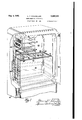
- Fig. 1 is a perspective view of one form of household refrigerator embodying my invention with the meat tender omitted to provide an unobstructed view of the glass partition;
- Fig. 2 is a top view of the partition shown in 1;
- Fig. 3 is a sectional view taken along the line 3--3 of Fig. 2 with the meat-tender shown in proper position;
- Fig. 4 is an enlarged view of the ventilating openingprovided in the mid-portion of the partition
- Fig. 5 is a sectional view showing the ventilating opening at one edge of the partition
- Fig. 6 is a sectional view taken along the lines 6-6 of Fig. 3;
- Fig. 7 is a front view of the meat-tender shown in Figs. 4 and 6.
- a household refrigerator in which the interior is divided into upper and lower compartments by a glass partition.
- the upper compartment is cooled directly by the primary evaporator operating below water freezing temperatures in order to freeze ice cubes, while the lower compartment is cooled by a secondary refrigerating circuit mounted upon the outside of its walls and cooled by the primary evaporator.
- a ventilating slot is provided in the mid-portion of the partition beneath a side wall of the evaporator while ventilating openings are also provided at the side edges of the partition This provides a lateral flow of dry air directly beneath the partition thereby keeping moisture off the partition
- a household refrigerator 20 provided with an upper cold dry storage compartment 22 separated by the generally imperforate horizontal glass partition 24 from a cold lower high humidity compartment 26.
- the upper compartment 22 is cooled directly by the primary evaporator 28 which also has shelves for receiving ice trays.
- the condensing portion 30 of a secondary refrigerant circuit is clamped to the side of the primary evaporator 28 and has its evaporating portion 32 wrapped around and clamped to the side, rear and bottom walls of the lower compartment 26.
- a sufiicient differential in temperature is provided between the primary and secondary circuits in order to keep the secondary circuit at temperatures above freezing. This arrangement makes it possible to maintain high humidities Within the lower compartment 26 without any material air circulation therein.
- I directly beneath the side wall of the evaporator 28, which is located substantially adjacent the vertical center line of the refrigerator, I provide a central ventilating opening 36 in the glass partition 24 between the metal bound panes of glass 38 and 40.
- This ventilating opening 36 is parallel with the side walls of the refrigerator and may be closed if desired by a metal flap 42.
- At the side edges of the partition 24 other ventilating openings are provided.
- I provide metal strips 46 and 64 fastened to the side walls of the compartment adjacent the edges of the partition. The shape of this metal strip on the side edges is best shown in Fig. 5.
- the metal strip 46 is shown as provided with a vertical flange 48 resting against the inner face 50 of one of the side walls of the inner liner of the cabinet.
- This flange 48 is fastened by means of a screw 52 to a clamping member 54 upon the opposite side of the inner lining member.
- This clamping member 54 also serves to clamp the secondary circuit to the walls of the lower compartment 26.
- a similar construction is used in connection with the other clamping members provided upon the opposite side wall of the lower compartment 26.
- the metal'strip 46 has a two-stepped horizontal portion including a slotted portion 56 which may be closed by a slide member 58 having slots which may .be brought into registration with the slots in the portion 56 to close the openings.
- This member 48 also has a second. step 50 which supports the adjacent edge of the partition 24. The edges of the partition are provided with metal reinforcing strips which contact the portion 68.
- the slots or openings in the member 46 are plainly shown in Fig. 2 and are designated by the reference character 62.
- a similar member 64 provided with ventilating slots 66 is provided at the opposite side.
- This member 64 is also provided with a closing member 68 having slots therein adapted to register with the slots 66 in the member 64 to provide ventilating openings upon this edge,
- the ventilating slots When the ventilating slots are open, the air which has been cooled and dried by contact with the side wall of the primary evaporator 28 falls downwardy and passes through the ventilating slot 36 after which it divides andmoves laterally in opposite directions from the slot 36 beneath the partition 24 after which it passes upwardly through the ventilating slots provided in the members 46 and 64.
- the partition 24 By this circulation of dry air, the partition 24 may be kept free from con- -densed moisture which obstructs the vision is provided with a stopping projection 94 which,
- the lid 16 not only forms a lid for the meat-tender 18 but also serves as a receptacle to collect water during a defrosting period when frost is melted off the primary evaporator 28.
- Wire posts extend downwardly at the four corners and are fastened to the metal edge portions of the glass partition 24.
- the glass partition 24 is provided with a rubber seal 88 extending entirely across the front face for making sealing contact with the door 98 of the cabinet in order to seal the lower compartment from the upper compartment. This seal 88 is held by the metal edge piece 92 provided upon the front edge of the partition 24.
- Refrigerating apparatus including a cabinet having walls defining a chamber therein, means 0 dividing the chamber into an upper and a lower member I8 is held in place by ears which are struck out from portions of the member 64.
- the closing members 58 and 68 are each provided with turned up projections 12 which serve as handles for operating the slide members 58 and 68.
- all the slots may be closed by their closing members; that is, the flap 42 may be moved to closed position as shown in Figs. 2, 3 and 4 and the slide closing members 58 and 68 may be moved so that the slots are not in registration to close the openings in the members 46 and 64.
- the flap 42 When ventilation is desired preferably the flap 42 is opened and the amount of ventilation concompartment, an evaporator of a closed primary refrigerating systemv disposed within said upper compartment and normally maintained at a temperature below that at which water freezes for maintaining the air therein at a low relative humidity, a closed secondary refrigerating circuit located within said cabinet and including a refrigerant condensing portion disposed in heat exchange relationship with said primary evaporator and a refrigerant evaporating portion disposed in heat exchange relationship with said lower compartment, said evaporating portion of said circuit being normally maintained above water freezing temperatures for cooling said lower compartment and for maintaining the air therein at a higher relative humidity with respect to the low relative humidity of the air within said upper compartment, said means being provided with openings adjacent opposite edges thereof and another opening intermediate its edges positioned below an edge of said evaporator for permitting ventilation between said compartments, said means being substantially imfrigerant condensing portion disposed in heat exchange relationship with said primary evaporaperforate intermediate the openings
- Refrigerating apparatus including a cabinet having walls defining a chamber therein, means dividing the chamber into a first and a second compartment, an evaporator 01 a closed primary refrigerating system disposed within said first compartment and normally maintained at a temperature below that at which water freezes for maintaining the air therein at a low relative humidity, a closed secondary refrigerating circuit located within said cabinet and including a retor and a refrigerant evaporating portion disposed in heat exchange relationship with said second compartment, said evaporating portion of said circuit being normally maintained above water freezing temperature for cooling said second compartment and for maintaining the air therein at a higher relative humidity with respect to the low relative humidity of the air within said first compartment, said means being provided with opposed openings located adjacent said chamber walls and another intermediate opening positioned adjacent an edge of said evaporator ior permitting ventilation between said compartments, said means being substantially imperforate intermediate the openings therein, and means for selectively closing at least said intermediate opening.
Landscapes
- Engineering & Computer Science (AREA)
- Chemical & Material Sciences (AREA)
- Combustion & Propulsion (AREA)
- Physics & Mathematics (AREA)
- Mechanical Engineering (AREA)
- Thermal Sciences (AREA)
- General Engineering & Computer Science (AREA)
- Cold Air Circulating Systems And Constructional Details In Refrigerators (AREA)
Description
1942- E. F. SCHWELLER REFRIGERATING APPARATUS Filed Sept. 26, 1940 4 Sheets-Sheet 1 NVENT OR.
ATTORNEYS 1942- E. F. SCHWELLER v REFRIGERATING APPARATUS Filed Sept. 26, 1940 4 Sheets-Sheet 2 mm II ll I n ulhr inl O O INVENT v W;
ATTORNEYS Allg- 1942- E. F. SCI- WELLER REFRIGERATING APPARATUS Filed Sept. 26, 1940 4 Sheets-Sheet 5 INV NTOR Aug. 4, 1942. E. F. SCHWELLER REFRIGERATING APPARATUS Filed Sept. 26, 1940 4 Sheets-Sheet 4 ATTORNEYS Patented Aug. 4, 1942 REFRIGERATING APPARATUS Edmund F. Schweller, Dayton, Ohio, assignor to General Motors Corporation, Dayton, Ohio, a corporation of Delaware Application September 26, 1940, Serial No. 358,486
2 Claims.
This invention relates to refrigerating apparatus and more particularly to household refrigerators of the multi-compartment type.
At present there is a. definite trend to household refrigerators of the multi-compartment type in which a glass shelf divides the interior of the refrigerator into an upper cold dry compartment and a lower cold moist compartment. The upper dry compartment is cooled normally directly by the freezing evaporator while the lower compartment may be cooled by a secondary circuit or by another section of the primary circuit. Normally, the cooling means for the lower compartment is maintained above freezing temperatures and moisture tends to collect upon the bottom of the horizontal glass partition. This obstructs the vision through the glass partition and this obstruction of vision has caused many complaints from customers.
It is an object of my invention to provide a simple effective means for keeping the partition between the upper and lower compartments of such a refrigerator free from moisture,
It is another object of my invention to provide a ventilating system for such a refrigerator which will keep free from moisture the partition between the upper and lower compartments.
It is still another object of my invention to provide ventilating openings in the partition of such a refrigerator which are located in such a manner so as to provide circulation sufficient to keep the partition free from moisture but directed in such a way that it sets up little or no circulation in the major portion'of the lower compartment.
Further objects and advantages of the present invention will be apparent from the following description reference being bad to the accompanying drawings, wherein a preferred form of the present invention is clearly shown.
In the drawings:
Fig. 1 is a perspective view of one form of household refrigerator embodying my invention with the meat tender omitted to provide an unobstructed view of the glass partition;
Fig. 2 is a top view of the partition shown in 1;
Fig. 3 is a sectional view taken along the line 3--3 of Fig. 2 with the meat-tender shown in proper position;
Fig. 4 is an enlarged view of the ventilating openingprovided in the mid-portion of the partition;
Fig. 5 is a sectional view showing the ventilating opening at one edge of the partition;
Fig. 6 is a sectional view taken along the lines 6-6 of Fig. 3; and
Fig. 7 is a front view of the meat-tender shown in Figs. 4 and 6.
Briefly, I have shown a household refrigerator in which the interior is divided into upper and lower compartments by a glass partition. The upper compartment is cooled directly by the primary evaporator operating below water freezing temperatures in order to freeze ice cubes, while the lower compartment is cooled by a secondary refrigerating circuit mounted upon the outside of its walls and cooled by the primary evaporator. In order to prevent moisture from collecting upon the glass partition, a ventilating slot is provided in the mid-portion of the partition beneath a side wall of the evaporator while ventilating openings are also provided at the side edges of the partition This provides a lateral flow of dry air directly beneath the partition thereby keeping moisture off the partition Referring now to the drawings and more particularly to Fig. 1, there is shown a household refrigerator 20 provided with an upper cold dry storage compartment 22 separated by the generally imperforate horizontal glass partition 24 from a cold lower high humidity compartment 26. The upper compartment 22 is cooled directly by the primary evaporator 28 which also has shelves for receiving ice trays. The condensing portion 30 of a secondary refrigerant circuit is clamped to the side of the primary evaporator 28 and has its evaporating portion 32 wrapped around and clamped to the side, rear and bottom walls of the lower compartment 26. A sufiicient differential in temperature is provided between the primary and secondary circuits in order to keep the secondary circuit at temperatures above freezing. This arrangement makes it possible to maintain high humidities Within the lower compartment 26 without any material air circulation therein.
Under such conditions many types of foodstufis, especially fruit and vegetables, are preserved in a most satisfactory manner. Such a system inherently causes the accumulation of moisture upon the walls of the compartment as well as the glass partition 24. When the air is sufficiently moist, it is impossible to cool the air without causing sweating. However, many purchasers and users of suchrefrigerators do not understand this and many complain about the presence of moisture in the lower compartment. Particularly, there have been complaints about moisture collecting upon the lower surface of the glass partition 24. This moisture is objectionable since it obstructs vision through the shelf and also makes the presence of moisture much more noticeable.
In order to overcome these objections I provide controlled ventilating openings in the glass accumulation of moisture and sweating in the lower compartment are considerably reduced and the complainants better satisfied.
Therefore directly beneath the side wall of the evaporator 28, which is located substantially adjacent the vertical center line of the refrigerator, I provide a central ventilating opening 36 in the glass partition 24 between the metal bound panes of glass 38 and 40. This ventilating opening 36 is parallel with the side walls of the refrigerator and may be closed if desired by a metal flap 42. At the side edges of the partition 24 other ventilating openings are provided. In order to provide these openings I provide metal strips 46 and 64 fastened to the side walls of the compartment adjacent the edges of the partition. The shape of this metal strip on the side edges is best shown in Fig. 5. In Fig. the metal strip 46 is shown as provided with a vertical flange 48 resting against the inner face 50 of one of the side walls of the inner liner of the cabinet. This flange 48 is fastened by means of a screw 52 to a clamping member 54 upon the opposite side of the inner lining member. This clamping member 54 also serves to clamp the secondary circuit to the walls of the lower compartment 26. A similar construction is used in connection with the other clamping members provided upon the opposite side wall of the lower compartment 26.
The metal'strip 46 has a two-stepped horizontal portion including a slotted portion 56 which may be closed by a slide member 58 having slots which may .be brought into registration with the slots in the portion 56 to close the openings. This member 48 also has a second. step 50 which supports the adjacent edge of the partition 24. The edges of the partition are provided with metal reinforcing strips which contact the portion 68. The slots or openings in the member 46 are plainly shown in Fig. 2 and are designated by the reference character 62.
At the opposite side a similar member 64 provided with ventilating slots 66 is provided. This member 64 is also provided with a closing member 68 having slots therein adapted to register with the slots 66 in the member 64 to provide ventilating openings upon this edge, The
trolled by adjusting the amount of opening provided by the slide members 58 and 64. In this way, a controlled amount of ventilation may be provided which will be just suflicient to remove the moisture from the lower face of the partition 24.
When the ventilating slots are open, the air which has been cooled and dried by contact with the side wall of the primary evaporator 28 falls downwardy and passes through the ventilating slot 36 after which it divides andmoves laterally in opposite directions from the slot 36 beneath the partition 24 after which it passes upwardly through the ventilating slots provided in the members 46 and 64. By this circulation of dry air, the partition 24 may be kept free from con- -densed moisture which obstructs the vision is provided with a stopping projection 94 which,
by engagement with the shoulder 96, is adapted to prevent the meat-tender from being unwittingly pulled too far forward. The lid 16 not only forms a lid for the meat-tender 18 but also serves as a receptacle to collect water during a defrosting period when frost is melted off the primary evaporator 28. Wire posts extend downwardly at the four corners and are fastened to the metal edge portions of the glass partition 24. The glass partition 24 is provided with a rubber seal 88 extending entirely across the front face for making sealing contact with the door 98 of the cabinet in order to seal the lower compartment from the upper compartment. This seal 88 is held by the metal edge piece 92 provided upon the front edge of the partition 24.
By this construction the objections made to this type of refrigerator are overcome, thereby satisfying purchasers of this improved type of refrigeration.
While the form of embodiment of the invention as herein disclosed, constitutes a preferred form, it isto be understood that other forms might be adopted, all coming within the scope of the claims which follow.
What is claimed is as follows:
1. Refrigerating apparatus including a cabinet having walls defining a chamber therein, means 0 dividing the chamber into an upper and a lower member I8 is held in place by ears which are struck out from portions of the member 64. The closing members 58 and 68 are each provided with turned up projections 12 which serve as handles for operating the slide members 58 and 68.
By this arrangement, when no ventilation is desired, all the slots may be closed by their closing members; that is, the flap 42 may be moved to closed position as shown in Figs. 2, 3 and 4 and the slide closing members 58 and 68 may be moved so that the slots are not in registration to close the openings in the members 46 and 64. When ventilation is desired preferably the flap 42 is opened and the amount of ventilation concompartment, an evaporator of a closed primary refrigerating systemv disposed within said upper compartment and normally maintained at a temperature below that at which water freezes for maintaining the air therein at a low relative humidity, a closed secondary refrigerating circuit located within said cabinet and including a refrigerant condensing portion disposed in heat exchange relationship with said primary evaporator and a refrigerant evaporating portion disposed in heat exchange relationship with said lower compartment, said evaporating portion of said circuit being normally maintained above water freezing temperatures for cooling said lower compartment and for maintaining the air therein at a higher relative humidity with respect to the low relative humidity of the air within said upper compartment, said means being provided with openings adjacent opposite edges thereof and another opening intermediate its edges positioned below an edge of said evaporator for permitting ventilation between said compartments, said means being substantially imfrigerant condensing portion disposed in heat exchange relationship with said primary evaporaperforate intermediate the openings therein, and
means for selectively closing at least said intermediate opening.
2. Refrigerating apparatus including a cabinet having walls defining a chamber therein, means dividing the chamber into a first and a second compartment, an evaporator 01 a closed primary refrigerating system disposed within said first compartment and normally maintained at a temperature below that at which water freezes for maintaining the air therein at a low relative humidity, a closed secondary refrigerating circuit located within said cabinet and including a retor and a refrigerant evaporating portion disposed in heat exchange relationship with said second compartment, said evaporating portion of said circuit being normally maintained above water freezing temperature for cooling said second compartment and for maintaining the air therein at a higher relative humidity with respect to the low relative humidity of the air within said first compartment, said means being provided with opposed openings located adjacent said chamber walls and another intermediate opening positioned adjacent an edge of said evaporator ior permitting ventilation between said compartments, said means being substantially imperforate intermediate the openings therein, and means for selectively closing at least said intermediate opening.
EDMUND F. SCHWELLER.
Priority Applications (1)
| Application Number | Priority Date | Filing Date | Title |
|---|---|---|---|
| US358486A US2292015A (en) | 1940-09-26 | 1940-09-26 | Refrigerating apparatus |
Applications Claiming Priority (1)
| Application Number | Priority Date | Filing Date | Title |
|---|---|---|---|
| US358486A US2292015A (en) | 1940-09-26 | 1940-09-26 | Refrigerating apparatus |
Publications (1)
| Publication Number | Publication Date |
|---|---|
| US2292015A true US2292015A (en) | 1942-08-04 |
Family
ID=23409841
Family Applications (1)
| Application Number | Title | Priority Date | Filing Date |
|---|---|---|---|
| US358486A Expired - Lifetime US2292015A (en) | 1940-09-26 | 1940-09-26 | Refrigerating apparatus |
Country Status (1)
| Country | Link |
|---|---|
| US (1) | US2292015A (en) |
Cited By (10)
| Publication number | Priority date | Publication date | Assignee | Title |
|---|---|---|---|---|
| US2429709A (en) * | 1945-04-27 | 1947-10-28 | Philco Corp | Shelf for refrigerator cabinets |
| US2444593A (en) * | 1944-07-31 | 1948-07-06 | Hussmann Refrigerator Co | Automatic temperature control for refrigerated open-top display cases |
| US2449824A (en) * | 1945-02-28 | 1948-09-21 | Philco Corp | Controlled humidity refrigerator |
| US2450305A (en) * | 1948-02-05 | 1948-09-28 | Philco Corp | Partition for refrigerators |
| US2450823A (en) * | 1944-06-30 | 1948-10-05 | Philco Corp | Humidity control means responsive to movements of a refrigerator door |
| US2454855A (en) * | 1945-07-10 | 1948-11-30 | Philco Corp | Refrigerator humidity control |
| US2493488A (en) * | 1945-03-21 | 1950-01-03 | Liquid Carbonic Corp | Two temperature refrigerator, including a humidity control system |
| US2783620A (en) * | 1954-04-19 | 1957-03-05 | Whirlpool Seeger Corp | Refrigeration system |
| US3261179A (en) * | 1964-10-26 | 1966-07-19 | Whirlpool Co | Adjustable shelves for vertical freezers |
| WO2009077338A1 (en) * | 2007-12-18 | 2009-06-25 | BSH Bosch und Siemens Hausgeräte GmbH | Refrigerator |
-
1940
- 1940-09-26 US US358486A patent/US2292015A/en not_active Expired - Lifetime
Cited By (10)
| Publication number | Priority date | Publication date | Assignee | Title |
|---|---|---|---|---|
| US2450823A (en) * | 1944-06-30 | 1948-10-05 | Philco Corp | Humidity control means responsive to movements of a refrigerator door |
| US2444593A (en) * | 1944-07-31 | 1948-07-06 | Hussmann Refrigerator Co | Automatic temperature control for refrigerated open-top display cases |
| US2449824A (en) * | 1945-02-28 | 1948-09-21 | Philco Corp | Controlled humidity refrigerator |
| US2493488A (en) * | 1945-03-21 | 1950-01-03 | Liquid Carbonic Corp | Two temperature refrigerator, including a humidity control system |
| US2429709A (en) * | 1945-04-27 | 1947-10-28 | Philco Corp | Shelf for refrigerator cabinets |
| US2454855A (en) * | 1945-07-10 | 1948-11-30 | Philco Corp | Refrigerator humidity control |
| US2450305A (en) * | 1948-02-05 | 1948-09-28 | Philco Corp | Partition for refrigerators |
| US2783620A (en) * | 1954-04-19 | 1957-03-05 | Whirlpool Seeger Corp | Refrigeration system |
| US3261179A (en) * | 1964-10-26 | 1966-07-19 | Whirlpool Co | Adjustable shelves for vertical freezers |
| WO2009077338A1 (en) * | 2007-12-18 | 2009-06-25 | BSH Bosch und Siemens Hausgeräte GmbH | Refrigerator |
Similar Documents
| Publication | Publication Date | Title |
|---|---|---|
| US2694906A (en) | Refrigerating apparatus having a hydrator receptacle | |
| US2709900A (en) | Refrigerator with air conditioned receptacle | |
| US2292015A (en) | Refrigerating apparatus | |
| US2241064A (en) | Food storage receptacle for refrigerators | |
| US2613509A (en) | Refrigerating apparatus | |
| US3009338A (en) | Refrigeration apparatus | |
| US2562057A (en) | Refrigerator cabinet having means for regulating air flow and means for collecting drip | |
| US2304411A (en) | Refrigerating apparatus | |
| US3203199A (en) | Refrigerating apparatus | |
| US2478017A (en) | Refrigerator having moisture control means | |
| US2297581A (en) | Refrigerator | |
| US3067588A (en) | Method and means for preserving fresh foods | |
| US2565995A (en) | Refrigerator cabinet construction | |
| US2739456A (en) | Two temperature refrigerator | |
| US3243972A (en) | Refrigerator cabinet | |
| US2510758A (en) | Refrigerator having a baffle structure | |
| US2429709A (en) | Shelf for refrigerator cabinets | |
| US2645909A (en) | Two-temperature refrigerator | |
| US2604762A (en) | Baffle structure for refrigerators | |
| US2430456A (en) | Two-temperature refrigerator | |
| US2581618A (en) | Refrigerator cabinet | |
| US2627729A (en) | Refrigerating apparatus | |
| US2310872A (en) | Refrigerator | |
| US2222543A (en) | Refrigerator | |
| US2741098A (en) | Two temperature refrigerator |