US2289045A - Overhead door construction - Google Patents
Overhead door construction Download PDFInfo
- Publication number
- US2289045A US2289045A US397256A US39725641A US2289045A US 2289045 A US2289045 A US 2289045A US 397256 A US397256 A US 397256A US 39725641 A US39725641 A US 39725641A US 2289045 A US2289045 A US 2289045A
- Authority
- US
- United States
- Prior art keywords
- door
- guideway
- track
- vertical
- overhead
- Prior art date
- Legal status (The legal status is an assumption and is not a legal conclusion. Google has not performed a legal analysis and makes no representation as to the accuracy of the status listed.)
- Expired - Lifetime
Links
- 238000010276 construction Methods 0.000 title description 17
- 238000013459 approach Methods 0.000 description 7
- 210000001364 upper extremity Anatomy 0.000 description 7
- 210000003414 extremity Anatomy 0.000 description 4
- 239000002023 wood Substances 0.000 description 4
- 230000007246 mechanism Effects 0.000 description 3
- 238000009434 installation Methods 0.000 description 2
- 239000000470 constituent Substances 0.000 description 1
- 230000000875 corresponding effect Effects 0.000 description 1
- 230000006872 improvement Effects 0.000 description 1
- 238000004519 manufacturing process Methods 0.000 description 1
- 239000000463 material Substances 0.000 description 1
- 239000002184 metal Substances 0.000 description 1
- 230000004048 modification Effects 0.000 description 1
- 238000012986 modification Methods 0.000 description 1
- 230000002093 peripheral effect Effects 0.000 description 1
- 238000007789 sealing Methods 0.000 description 1
Images


Classifications
-
- E—FIXED CONSTRUCTIONS
- E05—LOCKS; KEYS; WINDOW OR DOOR FITTINGS; SAFES
- E05D—HINGES OR SUSPENSION DEVICES FOR DOORS, WINDOWS OR WINGS
- E05D15/00—Suspension arrangements for wings
- E05D15/16—Suspension arrangements for wings for wings sliding vertically more or less in their own plane
- E05D15/24—Suspension arrangements for wings for wings sliding vertically more or less in their own plane consisting of parts connected at their edges
- E05D15/244—Upper part guiding means
- E05D15/248—Upper part guiding means with lever arms for producing an additional movement
-
- E—FIXED CONSTRUCTIONS
- E05—LOCKS; KEYS; WINDOW OR DOOR FITTINGS; SAFES
- E05D—HINGES OR SUSPENSION DEVICES FOR DOORS, WINDOWS OR WINGS
- E05D15/00—Suspension arrangements for wings
- E05D15/16—Suspension arrangements for wings for wings sliding vertically more or less in their own plane
- E05D15/165—Details, e.g. sliding or rolling guides
-
- E—FIXED CONSTRUCTIONS
- E05—LOCKS; KEYS; WINDOW OR DOOR FITTINGS; SAFES
- E05Y—INDEXING SCHEME ASSOCIATED WITH SUBCLASSES E05D AND E05F, RELATING TO CONSTRUCTION ELEMENTS, ELECTRIC CONTROL, POWER SUPPLY, POWER SIGNAL OR TRANSMISSION, USER INTERFACES, MOUNTING OR COUPLING, DETAILS, ACCESSORIES, AUXILIARY OPERATIONS NOT OTHERWISE PROVIDED FOR, APPLICATION THEREOF
- E05Y2900/00—Application of doors, windows, wings or fittings thereof
- E05Y2900/10—Application of doors, windows, wings or fittings thereof for buildings or parts thereof
- E05Y2900/13—Type of wing
- E05Y2900/132—Doors
Definitions
- This invention relates generally to overhead door constructions and more particularly to overhead door constructions wherein hingedly connected door panels are shiftable between vertical door closing position and open overhead position.
- the invention contemplates an overhead door arrangement wherein a plurality of hingedly connected door sections having track followers disposed along opposite side margins, some of which are intermediate and others adjacent the upper and lower margins of the door, are directed along double vertical guideways and a single horizontal guideway.
- a further object of the present invention is to provide an overhead door arrangement of the type set forth above wherein the track followers and guideways therefor are so arranged as to enable the installation of the structure in instances where a minimum amount of head room is available.
- the invention contemplates means associated with the uppermost section for swinging said section into closing relation with respect to the door jamb as the sections approach the limit of their door closing position.
- the invention contemplates an overhead door construction wherein track followers associated with the uppermost section and the follower members associated with the hinges of the sections are directed along a given guideway and follower members associated with the lowermost door section are directed along another guideway whereby to facilitate installation and operation of the door sections.
- Fig. 1 is a vertical sectional view of a building contemplated by the present invention, said view being taken substantially along the line l! of Fig. 2;
- Fig. 2 is a transverse vertical sectional view taken along the line 2--2 of Fig. 1;
- Fig. 3 is an enlarged fragmentary sectional view taken along the line 33 of Fig. 2 showing the door sections in their normal vertical closed position;
- Fig. 4 is a fragmentary detailed sectional view of the upper left hand corner of the structure shown in Fig. 3 to illustrate the position occupied by the lowermost door section when it has been shifted to its open overhead position;
- Fig. 5 is an enlarged fragmentary horizontal sectional view taken substantially along the line 5-5 of Fig. 3;
- Fig. 6 is a fragmentary vertical'sectional view taken substantially along the line 6-6 of Fig. 5 to more clearly illustrate the track follower or roller which is directed within the vertical guideway, one side of which is defined by the inner surface of the door jamb;
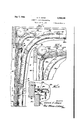
- Fig. 7 is an enlarged fragmentary vertical sectional view similar to Fig. 3 disclosing a modified overhead door arrangement wherein the double guideway is comprised of two adjacently positioned tracks which digress away from the door jamb toward their upper extremities to facilitate travel of the door sections;
- Fig. 8 is a fragmentary sectional view similar to Fig. '7 disclosing the door sections shifted to their upper or overhead position;
- Fig. 9 is an enlarged horizontal sectional view taken substantially along the line Q-El of Fig. 7.
- the invention contemplates an overhead door construction which includes a plurality of hingedly connected door sections iii, 12, i4 and i6. These sections Ill-l6 are connected by suitable hinges 18 disposed along opposite margins and each hinge member carries a track follower or roller 20. These track followers 20 are hereinafter referred to as intermediate followers or rollers inasmuch as they are positioned intermediate the upper and lower margins of the door.
- a track follower or roller 22 is associated at each side of the upper margin of the door and is carried at the free extremity of an arm 24 which is pivotally connected with a bracket 26 secured to the upper door section H] as clearly illustrated in Fig. 3.
- a coil spring 28 is interposed between equipped with an overhead door construction as the door section 10 and the arm 25 so as to continually urge said arm to the left as viewed in Fig. 3.
- aguide roller 30 carried by a pintle or stub shaft 32 secured to and extending outwardly from the side margin of the lowermost door section l6 (see Fig. 6).
- the outer extremity of the pintle or stub shaft 32 is connected to one extremity of a flexible lifting element or cable 34.
- This flexible lifting element 34 as shown in Figs. 1 and 2 extends upwardly to an idler or sheave 36 and thence rearwardly to a suitable counterbalancing mechanism designated generally by the numeral 31.
- the intermediate guide rollers are directed and guided within a substantially vertical track or guideway 38, a connecting curved track portion or guideway 40 and a substantially horizontal track or guideway 42.
- the roller 22 is also guided within the curved track or guideway portion 43 and the horizontal guideway 42.
- the roller is directed within a vertical guideway 44 which is defined by the inner surface 46 of the door jamb 48 and the adjacent tread portion 50 of the vertical guide track 38 (see Figs. 3 and 5).
- the guide roller 30 moves upwardly within the guideway 44 it eventually moves into the portion thereof which is bounded by the inner surface 45 of the door jamb 48 and a tread portion 52 which extends upwardly from and forms an extension of the tread portion 50 of the vertical guide track 38.
- the roller 30 eventually comes to rest within a curved track or guideway 54 which extends rearwardly from the guideway 44 as clearly illustrated in Fig. 4.
- This guideway 54 serves to prevent the lower margin of the door from moving into interference with the sheave wheel 36 as the door sections move suddenly to their overhead position.
- abutment 56 which limits the extent of rearward movement of the lowermost door section.
- This abutment 56 is positioned in the path of movement of the roller 30 and hence serves as an abutment therefor.
- This abutment 56, the structure of the track 54, the sheave and portions of the curved track and horizontal track 42 are secured to a gusset plate 58 which extends rearwardly from and is secured to the rear side of aheader 60.
- the upper or free margin of the door section i0 eventually swings into sealing engagement with the inner surfaces of the door jambs 48 and header 60. This is accomplished through the agency of the pivoted arm 24 which carries the roller 22.
- the quick closing of the uppermost panel is accomplished by means of the pivoted arm arrangement and as the door sections are initially shifted upwardly, the upper free margin of the section l0 swings rearwardly and eventually is brought to rest upon the adjacent edge or surface of the arm 24.
- rollers 30 are preferably made of wood or other material comparable thereto and are provided with a relatively wide face.
- wide face wooden rollers of the type disclosed herein function satisfactorily along the inner wooden surface of the door jamb.
- the wood to wood contact as distinguished from metal to wood contact reduces to a minimum the possibility of surface deformation and thus makes for long life, simplicity of construction and ease of operation.
- a slightly modified overhead door constructed is disclosed.
- the structure disclosed in Figs. 7 to 9, inclusive is similar to that disclosed in Figs, 1 to 6, inclusive, the only difference being in the use of a vertical guideway 44a which corresponds functionally with the guideway 44 previously described.
- the guideway 44 is defined on one side by the surface 46 of the door jamb and on the opposite side by the tread member 59 of the guideway or track 38.
- the vertical guideway 440 comprises a track member similar in cross-section to the track 38.
- Fig. 7 discloses the position occupied by the door sections IGI6 when they occupy their closed vertical position and Fig. 8 discloses the position occupied by said sections when they occupy their overhead position. In this open position the lower guide roller 38a comes to rest within the curved track portion 540.
- the invention contemplates an improved overhead door construction wherein either the door jamb or a track element per se functions in association with an adjacent guideway in directing intermediate and lower track rollers in their vertical travel.
- the double vertical guideway arrangement in combination with the hingedly connected door sections, the intermediate as well as the upper and lower track rollers are shifted into upper overhead position with minimum head room requirements. That is to say, by employing curved guideways of different radii, and double vertical guideways in association with the hingedly connected sections, the ease with which said sections may be shifted between vertical and open overhead position is greatly facilitated and the required head room is maintained at a desired minimum.
- the overhead door construction herein described is extremely economical to produce and simple to install. Also the invention enables the construction of an overhead door device with the use of a minimum number of constituent elements.
- An overhead door construction including a door comprising a plurality of hingedly connected door sections for traversing a door opening and adapted to be shifted between Vertical door closing position and open overhead position, track follower members disposed along opposite side margins of the door sections, certain of which are intermediate and others adjacent the upper and lower margins of said door, track s ructures for guiding said door sections, each track structure presenting a single horizontal guideway, a substantially vertical double guideway, an intermediate curved guideway for accommodating said intermediate track followers of the door and connecting said horizontal guideway with one of said vertical guideways, and a further guideway positioned outwardly from said curved guideway portion and connecting with the other vertical guideway, said further guideway including an upright portion and a rearwardly curved portion at the upper extremity of said upright portion, said rearwardly curved portion terminating short of said horizontal guideway for accommodating a follower member at the lower margin of said door as said door approaches the limit of its open overhead position.
- An overhead door construction including a door comprising a plurality of hingedly connected door sections for traversing a door opening and adapted to be shifted between vertical door closing position and open overhead position, track follower members disposed along opposite side margins of the door section, certain of which are intermediate and others adjacent the upper and lower margins of said door, track structures for guiding said door sections, each track structure presenting a single horizontal guideway, a substantially vertical double guideway, said double guideway comprising one guideway disposed in front of the other, an intermediate curved guideway for accommodating said intermediate track followers of the door and connecting said horizontal guideway with the rearwardly positioned vertical guideway, and a further guideway positioned outwardly from said curved guideway portion and connecting with the other vertical guideway, said further guideway including an upright portion and a rearwardly curved portion at the upper extremity of said upright portion, said rearwardly curved portion terminating short of said horizontal guideway for accommodating a follower member at the lower margin of said door as said door approaches the limit of its open overhead position.
- An overhead door construction including a door comprising a plurality of hingedly connected door sections for traversing a door opening and adapted to be shifted between vertical door closing position and open overhead position, track follower members disposed along opposite side margins of the door section, certain of which are intermediate and others adjacent the upper and lower margins of said door, track structures for guiding said door sections, each track structure presenting a single horizontal guideway, a substantially vertical double guideway, said double guideway comprising one guideway disposed in front of the other, an intermedaite curved guideway for accommodating said intermediate track followers of the door and connecting said horizontal guideway with the rearwardly positioned vertical guideway, and a further guideway positioned outwardly from said curved guideway portion and connecting with the other Vertical guideway, said further guideway including an upright portion and a rearwardly curved portion at the upper extremity of said upright portion, said rearwardly curved portion terminating short of said horizontal guideway for accommodating a follower member at the lower margin of said door as said door approaches the limit of its open overhead
- An overhead door construction including a door comprising a plurality of hingedly connected door sections for traversing a door opening and adapted to be shifted between vertical door closing position and open overhead position, track follower members disposed along opposite side margins of the door section, certain of which are intermediate and others adjacent the upper and lower margins of said door, track structures for guiding said door sections, each track structure presenting a single horizontal guideway, a substantially vertical double guideway, said double guideway comprising one guideway disposed in front of the other, an intermediate curved guideway for accommodating said intermediate track followers of the door and connecting said horizontal guideway with the rearwardly positioned vertical guideway, and a further guideway positioned outwardly from said curved guideway portion and connecting with the other vertical guideway, said further guideway including an upright portion and a rearwardly curved portion at the upper extremity of said upright portion, said rearwardly curved portion terminating short of said horizontal guideway for accommodating a follower member at the lower margin of said door as said door approaches the limit of its open overhead position, said vertical
Landscapes
- Engineering & Computer Science (AREA)
- Mechanical Engineering (AREA)
- Wing Frames And Configurations (AREA)
Description
' July 7, 1942.
A. V. ROWE Filed June 9, 1941 3 Sheets-Sheet l 56* Lagfig) M W 5 v W)"1 lMfifw IHHHI'HM,AW I,
r/[mum' W W W J6 x y 1942. A. v. ROWE 2,289,045
OVERHEAD DOOR CONSTRUCTION Filed June 9, 1941 3 Sheets-Sheet 2 y 1942. A. v. ROWE 2,289,045
OVERHEAD DOOR CONSTRUCTION Filed June 9, 1941 3 Sheets-Sheet 3 ,7" k a 4/2, 1 [56 I w |l| O I I' l l llll 7 Q I] 111 I I; I I
l ll lillllll l|llllllfII.
Patented July 7, 1942 OVERHEAD DOOR CONSTRUCTION Alvin V. Rowe, Galesburg, 111., assignor to Rowe Manufacturing Company, Galesburg, 111., a corporation of Illinois Application June 9, 1941, Serial No. 397,256
Claims.
This invention relates generally to overhead door constructions and more particularly to overhead door constructions wherein hingedly connected door panels are shiftable between vertical door closing position and open overhead position.
It is one of the objects of the present invention to provide an overhead door arrangement equipped with track follower members along opposite margins thereof and guideways cooperating therewith which are so disposed as to greatly facilitate the ease with which certain of the track followers may be guided in a given direction and others guided in a different direction.
More specifically the invention contemplates an overhead door arrangement wherein a plurality of hingedly connected door sections having track followers disposed along opposite side margins, some of which are intermediate and others adjacent the upper and lower margins of the door, are directed along double vertical guideways and a single horizontal guideway.
It is a further object of the present invention to provide in association with hingedly connected door panels and track followers, as set forth above, guideways wherein one of the vertical double guideways is defined on one side by the inner surface of the door jamb.
A further object of the present invention is to provide an overhead door arrangement of the type set forth above wherein the track followers and guideways therefor are so arranged as to enable the installation of the structure in instances where a minimum amount of head room is available. To this end the invention contemplates means associated with the uppermost section for swinging said section into closing relation with respect to the door jamb as the sections approach the limit of their door closing position.
Still more specifically the invention contemplates an overhead door construction wherein track followers associated with the uppermost section and the follower members associated with the hinges of the sections are directed along a given guideway and follower members associated with the lowermost door section are directed along another guideway whereby to facilitate installation and operation of the door sections.
The foregoing and other objects and advantages will be more apparent from the following detailed description when considered in connection with the accompanying drawings wherein- Fig. 1 is a vertical sectional view of a building contemplated by the present invention, said view being taken substantially along the line l! of Fig. 2;
Fig. 2 is a transverse vertical sectional view taken along the line 2--2 of Fig. 1;
Fig. 3 is an enlarged fragmentary sectional view taken along the line 33 of Fig. 2 showing the door sections in their normal vertical closed position;
Fig. 4 is a fragmentary detailed sectional view of the upper left hand corner of the structure shown in Fig. 3 to illustrate the position occupied by the lowermost door section when it has been shifted to its open overhead position;
Fig. 5 is an enlarged fragmentary horizontal sectional view taken substantially along the line 5-5 of Fig. 3;
Fig. 6 is a fragmentary vertical'sectional view taken substantially along the line 6-6 of Fig. 5 to more clearly illustrate the track follower or roller which is directed within the vertical guideway, one side of which is defined by the inner surface of the door jamb;
Fig. 7 is an enlarged fragmentary vertical sectional view similar to Fig. 3 disclosing a modified overhead door arrangement wherein the double guideway is comprised of two adjacently positioned tracks which digress away from the door jamb toward their upper extremities to facilitate travel of the door sections;
Fig. 8 is a fragmentary sectional view similar to Fig. '7 disclosing the door sections shifted to their upper or overhead position; and
Fig. 9 is an enlarged horizontal sectional view taken substantially along the line Q-El of Fig. 7.
Referring now to the drawings wherein like numerals have been employed to designate similar parts throughout the various figures, it will be seen that the invention contemplates an overhead door construction which includes a plurality of hingedly connected door sections iii, 12, i4 and i6. These sections Ill-l6 are connected by suitable hinges 18 disposed along opposite margins and each hinge member carries a track follower or roller 20. These track followers 20 are hereinafter referred to as intermediate followers or rollers inasmuch as they are positioned intermediate the upper and lower margins of the door.
A track follower or roller 22 is associated at each side of the upper margin of the door and is carried at the free extremity of an arm 24 which is pivotally connected with a bracket 26 secured to the upper door section H] as clearly illustrated in Fig. 3. A coil spring 28 is interposed between equipped with an overhead door construction as the door section 10 and the arm 25 so as to continually urge said arm to the left as viewed in Fig. 3.
At each side of the lower margin of the door is aguide roller 30 carried by a pintle or stub shaft 32 secured to and extending outwardly from the side margin of the lowermost door section l6 (see Fig. 6). The outer extremity of the pintle or stub shaft 32 is connected to one extremity of a flexible lifting element or cable 34. This flexible lifting element 34 as shown in Figs. 1 and 2 extends upwardly to an idler or sheave 36 and thence rearwardly to a suitable counterbalancing mechanism designated generally by the numeral 31. Inasmuch as the present invention is not particularly concerned with the type of counterbalancing mechanism which may be used, said mechanism is not disclosed in detail and it will sufiice to say that anysuitable means for counterbalancing the weight of thedoorsections Ill-l6 may be employed.
Attention is directed to the fact that the intermediate guide rollers are directed and guided within a substantially vertical track or guideway 38, a connecting curved track portion or guideway 40 and a substantially horizontal track or guideway 42. The roller 22 is also guided within the curved track or guideway portion 43 and the horizontal guideway 42. The roller is directed within a vertical guideway 44 which is defined by the inner surface 46 of the door jamb 48 and the adjacent tread portion 50 of the vertical guide track 38 (see Figs. 3 and 5). As the guide roller 30 moves upwardly within the guideway 44 it eventually moves into the portion thereof which is bounded by the inner surface 45 of the door jamb 48 and a tread portion 52 which extends upwardly from and forms an extension of the tread portion 50 of the vertical guide track 38. The roller 30 eventually comes to rest within a curved track or guideway 54 which extends rearwardly from the guideway 44 as clearly illustrated in Fig. 4. This guideway 54 serves to prevent the lower margin of the door from moving into interference with the sheave wheel 36 as the door sections move suddenly to their overhead position. Associated with the rearward extremity of the guideway 54 is an abutment 56 which limits the extent of rearward movement of the lowermost door section. This abutment 56 is positioned in the path of movement of the roller 30 and hence serves as an abutment therefor. This abutment 56, the structure of the track 54, the sheave and portions of the curved track and horizontal track 42 are secured to a gusset plate 58 which extends rearwardly from and is secured to the rear side of aheader 60.
As the door sections are moved from their open overhead position as shown in Fig. 4 toward the closed vertical position shown in Figs. 1 and 2, the upper or free margin of the door section i0 eventually swings into sealing engagement with the inner surfaces of the door jambs 48 and header 60. This is accomplished through the agency of the pivoted arm 24 which carries the roller 22. Thus the quick closing of the uppermost panel is accomplished by means of the pivoted arm arrangement and as the door sections are initially shifted upwardly, the upper free margin of the section l0 swings rearwardly and eventually is brought to rest upon the adjacent edge or surface of the arm 24.
Attention is directed to the structural features of the guide rollers 30. These rollers are preferably made of wood or other material comparable thereto and are provided with a relatively wide face. Experience has shown that wide face wooden rollers of the type disclosed herein function satisfactorily along the inner wooden surface of the door jamb. The wood to wood contact as distinguished from metal to wood contact reduces to a minimum the possibility of surface deformation and thus makes for long life, simplicity of construction and ease of operation.
In Figs. 7 to 9, inclusive, a slightly modified overhead door constructed is disclosed. The structure disclosed in Figs. 7 to 9, inclusive, is similar to that disclosed in Figs, 1 to 6, inclusive, the only difference being in the use of a vertical guideway 44a which corresponds functionally with the guideway 44 previously described. As previously described the guideway 44 is defined on one side by the surface 46 of the door jamb and on the opposite side by the tread member 59 of the guideway or track 38. The vertical guideway 440. on the other hand comprises a track member similar in cross-section to the track 38. In Figs. 7 to 9, inclusive, I have designated the inner guideway or track by the numeral 38a. It will also be noted that the guideways 38a and 44a toward their upper extremities incline slightly away from the door jamb to a given point designated generally by the letter A. From this point the curved track or guideway 43a curves rearwardly and connects with the horizontal guideway 42a. The inclined portion of the guideway 44a from the point A extends vertically upward and connects with a curved track or guideway portion 54a which corresponds functionally with the guideway 54 previously described. All other elements, with the exception of the lower roller 30a, disclosed in Figs. 7 to 9, inclusive, are substantially identical in structural and functional characteristics to the correspond ing elements shown in Figs. 1 to 6, inclusive, and hence are designated by like numerals. Fig. 7 discloses the position occupied by the door sections IGI6 when they occupy their closed vertical position and Fig. 8 discloses the position occupied by said sections when they occupy their overhead position. In this open position the lower guide roller 38a comes to rest within the curved track portion 540.. Fig. 9, which is a transverse horizontal section, discloses the manner in which the two Vertical guideways or track structures 38a and 44a are adjacently positioned.
By having the upper portion of the vertical guideways inclined slightly rearwardly the clearance of the lower outer corner of the door section It, as it approaches its uppermost overhead position, is positively precluded. Experience has shown that unless some means is provided to take care of this situation it becomes necessary to chamfer the lower corner of the door. By employing the improvement disclosed herein the aforesaid corner is shifted a suificient distance away from the door jamb as it shifts along the curved track to avoid any interference between the corner of the door section and said jamb.
It will be apparent from the foregoing description that the invention contemplates an improved overhead door construction wherein either the door jamb or a track element per se functions in association with an adjacent guideway in directing intermediate and lower track rollers in their vertical travel. By employing the double vertical guideway arrangement in combination with the hingedly connected door sections, the intermediate as well as the upper and lower track rollers are shifted into upper overhead position with minimum head room requirements. That is to say, by employing curved guideways of different radii, and double vertical guideways in association with the hingedly connected sections, the ease with which said sections may be shifted between vertical and open overhead position is greatly facilitated and the required head room is maintained at a desired minimum.
The invention disclosed herein is related to the invention set forth in my earlier filed application, Serial No. 337,344, filed May 27, 1940, now Patent No. 2,264,642, patented December 2, 1941, in that both the present application and my above mentioned application disclose double vertical guideways cooperatively arranged with respect to a single horizontal guideway.
It will also be apparent that the amount of required head room is held to a minimum by reason of the single horizontal guideway which cooperates with the double guideway in properly positioning and guiding the shiftable door sections.
The overhead door construction herein described is extremely economical to produce and simple to install. Also the invention enables the construction of an overhead door device with the use of a minimum number of constituent elements.
Obviously the invention is not limited to the specific structural details disclosed herein but is capable of other modifications and changes without departing from the spirit and scope of the claims appended hereto.
The invention is hereby claimed as follows:
1. An overhead door construction including a door comprising a plurality of hingedly connected door sections for traversing a door opening and adapted to be shifted between Vertical door closing position and open overhead position, track follower members disposed along opposite side margins of the door sections, certain of which are intermediate and others adjacent the upper and lower margins of said door, track s ructures for guiding said door sections, each track structure presenting a single horizontal guideway, a substantially vertical double guideway, an intermediate curved guideway for accommodating said intermediate track followers of the door and connecting said horizontal guideway with one of said vertical guideways, and a further guideway positioned outwardly from said curved guideway portion and connecting with the other vertical guideway, said further guideway including an upright portion and a rearwardly curved portion at the upper extremity of said upright portion, said rearwardly curved portion terminating short of said horizontal guideway for accommodating a follower member at the lower margin of said door as said door approaches the limit of its open overhead position.
2. An overhead door construction including a door comprising a plurality of hingedly connected door sections for traversing a door opening and adapted to be shifted between vertical door closing position and open overhead position, track follower members disposed along opposite side margins of the door section, certain of which are intermediate and others adjacent the upper and lower margins of said door, track structures for guiding said door sections, each track structure presenting a single horizontal guideway, a substantially vertical double guideway, said double guideway comprising one guideway disposed in front of the other, an intermediate curved guideway for accommodating said intermediate track followers of the door and connecting said horizontal guideway with the rearwardly positioned vertical guideway, and a further guideway positioned outwardly from said curved guideway portion and connecting with the other vertical guideway, said further guideway including an upright portion and a rearwardly curved portion at the upper extremity of said upright portion, said rearwardly curved portion terminating short of said horizontal guideway for accommodating a follower member at the lower margin of said door as said door approaches the limit of its open overhead position.
3. An overhead door construction including a door comprising a plurality of hingedly connected door sections for traversing a door opening and adapted to be shifted between vertical door closing position and open overhead position, track follower members disposed along opposite side margins of the door section, certain of which are intermediate and others adjacent the upper and lower margins of said door, track structures for guiding said door sections, each track structure presenting a single horizontal guideway, a substantially vertical double guideway, said double guideway comprising one guideway disposed in front of the other, an intermedaite curved guideway for accommodating said intermediate track followers of the door and connecting said horizontal guideway with the rearwardly positioned vertical guideway, and a further guideway positioned outwardly from said curved guideway portion and connecting with the other Vertical guideway, said further guideway including an upright portion and a rearwardly curved portion at the upper extremity of said upright portion, said rearwardly curved portion terminating short of said horizontal guideway for accommodating a follower member at the lower margin of said door as said door approaches the limit of its open overhead position, said vertical double guideway comprising a front guideway defined on one side by the inner surface of the door jamb.
4. An overhead door construction including a door comprising a plurality of hingedly connected door sections for traversing a door opening and adapted to be shifted between vertical door closing position and open overhead position, track follower members disposed along opposite side margins of the door section, certain of which are intermediate and others adjacent the upper and lower margins of said door, track structures for guiding said door sections, each track structure presenting a single horizontal guideway, a substantially vertical double guideway, said double guideway comprising one guideway disposed in front of the other, an intermediate curved guideway for accommodating said intermediate track followers of the door and connecting said horizontal guideway with the rearwardly positioned vertical guideway, and a further guideway positioned outwardly from said curved guideway portion and connecting with the other vertical guideway, said further guideway including an upright portion and a rearwardly curved portion at the upper extremity of said upright portion, said rearwardly curved portion terminating short of said horizontal guideway for accommodating a follower member at the lower margin of said door as said door approaches the limit of its open overhead position, said vertical double guideway comprising a rearward vertical guideway spaced from said jamb and a front guideway defined on the rearward side by a portion of of which are intermediate and others adjacent 10 the upper and lower margins of said door, track structures for guiding said door sections, each track structure presenting a single horizontal guideway, a substantially vertical double guideway, said double guideway comprising one guideway disposed in front of the other, an intermediate curved guideway for accommodating said intermediate track followers of the door and connecting said horizontal guideway with the rearwardly positioned vertical guideway, and a further guideway positioned outwardly from said curved guideway portion and connecting with the other vertical guideway, said further guide- Way including an upright portion and a rearwardly curved portion at the upper extremity of said upright portion, said rearwardly curved portion terminating short of said horizontal guideway for accommodating a follower member at the lower margin of said door as said door approaches the limit of its open overhead position, the lower follower members comprising rollers having a relatively wide, substantially fiat peripheral surface adapted for engagement with the inner surface of the door jamb.
ALVIN V. ROWE.
Priority Applications (1)
| Application Number | Priority Date | Filing Date | Title |
|---|---|---|---|
| US397256A US2289045A (en) | 1941-06-09 | 1941-06-09 | Overhead door construction |
Applications Claiming Priority (1)
| Application Number | Priority Date | Filing Date | Title |
|---|---|---|---|
| US397256A US2289045A (en) | 1941-06-09 | 1941-06-09 | Overhead door construction |
Publications (1)
| Publication Number | Publication Date |
|---|---|
| US2289045A true US2289045A (en) | 1942-07-07 |
Family
ID=23570450
Family Applications (1)
| Application Number | Title | Priority Date | Filing Date |
|---|---|---|---|
| US397256A Expired - Lifetime US2289045A (en) | 1941-06-09 | 1941-06-09 | Overhead door construction |
Country Status (1)
| Country | Link |
|---|---|
| US (1) | US2289045A (en) |
Cited By (3)
| Publication number | Priority date | Publication date | Assignee | Title |
|---|---|---|---|---|
| US4095641A (en) * | 1975-12-15 | 1978-06-20 | Bruce Edgar Olson | Attachment for an overhead door |
| DE3135400A1 (en) * | 1981-09-07 | 1983-03-24 | Hörmann KG Brockhagen, 4803 Steinhagen | Sectional door |
| EP1148198A3 (en) * | 2000-04-19 | 2003-11-19 | Overhead Door Corporation | Bottom bracket for upward acting door |
-
1941
- 1941-06-09 US US397256A patent/US2289045A/en not_active Expired - Lifetime
Cited By (3)
| Publication number | Priority date | Publication date | Assignee | Title |
|---|---|---|---|---|
| US4095641A (en) * | 1975-12-15 | 1978-06-20 | Bruce Edgar Olson | Attachment for an overhead door |
| DE3135400A1 (en) * | 1981-09-07 | 1983-03-24 | Hörmann KG Brockhagen, 4803 Steinhagen | Sectional door |
| EP1148198A3 (en) * | 2000-04-19 | 2003-11-19 | Overhead Door Corporation | Bottom bracket for upward acting door |
Similar Documents
| Publication | Publication Date | Title |
|---|---|---|
| US2837151A (en) | Upwardly acting door assemblies provided with weather seals | |
| US2264642A (en) | Overhead door construction | |
| US2072092A (en) | Vertically sliding door construction | |
| US2327778A (en) | Garage door | |
| US2040080A (en) | Overhead door | |
| US2039296A (en) | Sliding door | |
| US2289045A (en) | Overhead door construction | |
| US2142562A (en) | Braking mechanism for rolling closures | |
| US2291583A (en) | Overhead door construction | |
| US2023664A (en) | Sliding door construction | |
| US2008000A (en) | Overhead door and operating mechanism | |
| US2072514A (en) | Sectional doorway | |
| US1948770A (en) | Door construction | |
| US1940485A (en) | Door operating mechanism | |
| US2196903A (en) | Overhead door track construction | |
| US1990470A (en) | Sliding door construction | |
| US2530263A (en) | Balanced door | |
| US2294361A (en) | Closure device for vertically acting doors | |
| US7055573B2 (en) | Systems and methods for reducing gap space between door sections | |
| US1820195A (en) | Garage door | |
| US2869637A (en) | Upwardly acting door assembly | |
| US2264643A (en) | Overhead door construction | |
| US1865568A (en) | Movable molding for doors and the like | |
| US1420087A (en) | Garage-door construction | |
| US2531119A (en) | Automatic door |