US2192631A - Automatic fuel ignition - Google Patents
Automatic fuel ignition Download PDFInfo
- Publication number
- US2192631A US2192631A US13684737A US2192631A US 2192631 A US2192631 A US 2192631A US 13684737 A US13684737 A US 13684737A US 2192631 A US2192631 A US 2192631A
- Authority
- US
- United States
- Prior art keywords
- igniter
- pilot
- valve
- circuit
- coil
- Prior art date
- Legal status (The legal status is an assumption and is not a legal conclusion. Google has not performed a legal analysis and makes no representation as to the accuracy of the status listed.)
- Expired - Lifetime
Links
- 239000000446 fuel Substances 0.000 title description 42
- 239000004020 conductor Substances 0.000 description 37
- 238000010438 heat treatment Methods 0.000 description 18
- 239000002184 metal Substances 0.000 description 11
- 210000003414 extremity Anatomy 0.000 description 5
- 230000000694 effects Effects 0.000 description 4
- 230000009471 action Effects 0.000 description 3
- 230000004044 response Effects 0.000 description 3
- 238000001816 cooling Methods 0.000 description 2
- 239000012530 fluid Substances 0.000 description 2
- 238000009413 insulation Methods 0.000 description 2
- 210000003141 lower extremity Anatomy 0.000 description 2
- 210000002445 nipple Anatomy 0.000 description 2
- 238000013459 approach Methods 0.000 description 1
- 230000008859 change Effects 0.000 description 1
- 238000010586 diagram Methods 0.000 description 1
- 238000005485 electric heating Methods 0.000 description 1
- 239000011810 insulating material Substances 0.000 description 1
- 239000010985 leather Substances 0.000 description 1
- 239000007788 liquid Substances 0.000 description 1
- 230000004048 modification Effects 0.000 description 1
- 238000012986 modification Methods 0.000 description 1
- 238000000926 separation method Methods 0.000 description 1
- 125000006850 spacer group Chemical group 0.000 description 1
Images

Classifications
-
- F—MECHANICAL ENGINEERING; LIGHTING; HEATING; WEAPONS; BLASTING
- F23—COMBUSTION APPARATUS; COMBUSTION PROCESSES
- F23D—BURNERS
- F23D14/00—Burners for combustion of a gas, e.g. of a gas stored under pressure as a liquid
- F23D14/02—Premix gas burners, i.e. in which gaseous fuel is mixed with combustion air upstream of the combustion zone
-
- F—MECHANICAL ENGINEERING; LIGHTING; HEATING; WEAPONS; BLASTING
- F24—HEATING; RANGES; VENTILATING
- F24H—FLUID HEATERS, e.g. WATER OR AIR HEATERS, HAVING HEAT-GENERATING MEANS, e.g. HEAT PUMPS, IN GENERAL
- F24H9/00—Details
- F24H9/20—Arrangement or mounting of control or safety devices
-
- Y—GENERAL TAGGING OF NEW TECHNOLOGICAL DEVELOPMENTS; GENERAL TAGGING OF CROSS-SECTIONAL TECHNOLOGIES SPANNING OVER SEVERAL SECTIONS OF THE IPC; TECHNICAL SUBJECTS COVERED BY FORMER USPC CROSS-REFERENCE ART COLLECTIONS [XRACs] AND DIGESTS
- Y10—TECHNICAL SUBJECTS COVERED BY FORMER USPC
- Y10T—TECHNICAL SUBJECTS COVERED BY FORMER US CLASSIFICATION
- Y10T137/00—Fluid handling
- Y10T137/1407—Combustion failure responsive fuel safety cut-off for burners
Definitions
- This invention relates to improvements in automatic fuel ignition, and has to do particularly with apparatus and electrical controls for normally shutting off the pilot burner, for turning it on and igniting it automatically when a room thermostat calls for heat, and for turning it off prior to the time when the room thermostat causes the main burner to be extinguished.
- the ignition cycle begins over again. If the fuel supply remains off, the ignition cycle may be'repeated a number of times without effect, but when the fuel supply is resumed the burner automatically starts again.
- Another object is the provision of means for lengthening the life of the igniter by making its operation intermittent rather than continuous.
- a further object is the provision of novel apparatus for electrically controlling the pilot fuel valve and for causing intermittent energization of the igniter coil.
- Still another object is the provision of means for cutting off the igniter at the same time that the main fuel valve is opened.
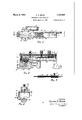
- Fig. 1 is a plan view of a combined pilot fuel valve and ignition interrupter which may be employed in carrying out the invention
- Fig. 2 is a vertical sectional view of the same taken substantially on the line 2-2 of Fig. 1;
- Fig. 3 is a fragmental vertical sectional view, corresponding to a portionof Fig. 2, showing the parts on a larger scale; 7
- Fig. 4 is an end view of the apparatus of Figs. 1 and 2; I f
- Fig. 5 is a diagram of my system showing the electrical controls and conductors.
- Fig. 6 is a view similar to Fig. 5, illustrating a modification.
- a main gas burner is shown at I0. It will be understood that the invention is applicable to a burner using a fluid fuel, but I have illustrated it herein as applied to a gas burner and it will be so described hereinafter.
- a valve I2 which is electrically operated. This valve may be a diaphragm valve controlled by a solenoid or it may be motor operated, but for the sake of simplicity it is herein shown as attached directly to the armature l3 of a solenoid l4, so as to .be open when the solenoid is energized.
- a tube I5 is connected with gas line H to the rear of valve l2 and serves as a conductor for gas flowing toward the pilot, which is represented at I6.
- the pilot is supplied with two gas exit ports, shown at I! and Hi.
- gas flows out of port I! it envelopes an electric igniter coil l9, and if that coil is sufficiently hot the gas will be ignited. The heat of the flame will then cause the stream of gas to take an upward course and the flame will heat the shorter one of two interconnected thermal "members and 2
- is relatively long and, at its lower extremity, is attached to a substantially horizontal rod 24 carrying a beveled head 25.
- the heat of the flame from the pilot port ll causes the thermal member an to expand and lengthen, whereupon member 2
- the beveled head 25 is adapted to engage the middle blade -26 of a double-throw switch, and thereby raise that blade out of contact with the lower blade 21 and into contact with the upper blade 28.
- Line wires 29 and 30 supply current to the primary coil of a step-down transformer 3
- This transformer is preferably one of the constant current, high impedance type, although other transformers of the proper power rating may be used provided they are not of the constant voltage type.
- a room thermostat, indicated at 32, has two sets of contacts 33 and 34 so mounted that when the thermostat calls for heat contacts 33 close first and contacts 3! follow when post.
- the fixed end of the thermostat is connected by a conductor 35 with a stationary contact 36 that is adapted to be engaged by a contact 31 carried by armature I3 when the solenoid I4 is energized.
- the solenoid is "alsoconnected with the contact 31 by a flexible conductor 38.
- This piece of apparatus comprises a casing 39 with a cover 40 of insulating material, removably attached thereto by screws M and 42, and a depending extension 43 with a nipple 44 for the reception of one end of the tube or pipe I5.
- the extension 43 has a pocket 45 formed therein, connected with the bore of nipple 44 by suitable passages.
- a light spiral spring 48 tends to hold the valve piece in its upper open position
- a central post on the valve piece projects upwardly through a central opening in a flexible diaphragm 49, a collar 50 surrounding the post and the latter being peened or riveted over to clamp the diaphragm and pro vide a fluid tight joint.
- is superimposed upon the rim of the diaphragm and is fastened down tightly by screws 52, thereby forming a seal around the upper, outer edge of the pocket 45.
- the bi-metal thermal element 53 is a bi-metal thermal element, having a knob 54 on its free extremity, adapted to contact the top of valve piece 41 and depress the valve against the action of spring 48. This condition obtains when the bi-metal strip is not heated.
- the right hand end of strip 53 is fixed to the cover 40 by means of a screw 55 and a bolt 56, the latter projecting upwardly above the cover and serving as a binding post.
- a spacing block 51 of insulation is interposed between the strip and the cover.
- the bi-metal strip has wound thereon a heating coil 58, which is electrically connected at one extremity to the strip by means of a clamp 59, and at other points is insulated from the strip by an insulating envelope 60.
- the opposite extremity of the coil is clamped in position over the insulation by means of ametal clamping band 6I.
- An adjustable binding post 62 mounted in the cover, engages clamping band 6I.
- the screw 64 also serves as a binding
- the casing 39 is open at the valve end so as to make it possible to observe the valve movements'.
- the cover at this point is supported by .a spacer block 65, through which the screw 42 extends.
- a gas 'exit passage 66 connects pocket 45 with a further passage 61 in an arm of the casing, and to this exit passage is connected the pilot pipe I6.
- Binding post 56 on the cover of the pilot control apparatus, is connected by a conductor 68 with one end of the secondary coil of the transformer 3
- the third binding post 64 is connected by a conductor 10 with one end of the igniter coil I9. From the opposite end of that coil a conductor 1I leads to the lower blade 21 of the double-throw switch.
- the transformer secondary is also connected by a conductor 12 with the stationary member of the thermostat contacts 33, while a branch conductor 13, with a hand switch 14 therein, is connected with the upper end of solenoid I4.
- the middle blade 26 of the double-throw switch is connected by aconductor 15 with the stationary part of thermostat contacts 33 and the conductor 12, whereas in Fig. 6 the middle blade 26 of the switch is connected by a conductor 16 with the stationary thermostat contact 34 and the conductor 69.
- the upper blade 28 of the switch in both instances is connectedwith the upper end of solenoid I4 by a conductor 11.
- the lower end of the solenoid is connected by conductor 18 -to conductor 68.
- a circuit is set up from the transformer through conductor 12, contacts 33 and 34 and conductor 69 to binding post 62, and then through clamping band 6I and heating coil 58 to bi-metal thermal strip 53, through that strip to binding post 56 and back through conductor 68 to the transformer.
- Current traversing this circuit gradually heats up the coil 58 which warps the bimetal strip 53, causing the free end thereof to swing upwardly.
- the pressure of knob 54 upon the valve piece 41 is thus relieved and the spring 48 opens the valve, enabling gas to flow through tube I5 into pocket 45 and thence out through passages 66 and 61 to pilot pipe I6, from which it flows through ports I1 and I8.
- the stream of gas emerging from port I1 envelopes the igniter coil I9.
- heating coil 58 continues and increases the warping of element 53 until the contact 63 on the bi-metal strip engages with screw 64.
- this latter contact is made a circuit is set up from the transformer,' through conductors 12 and 15 to the middle blade 26 of the double-throw switch,
- Igniter coil I3 is thus brought up to a high heat, and if suflicient gas from the pilot burner port I! is present the gas, is ignited. The electrical energy consumed in the heating of igniter coil l8, lowers the voltage in the circuits fed by the transformer.
- solenoid I The circuit through the igniter coil is thereby broken and a circuit is set up through solenoid I as follows: From the transformer through conductors I2 and I6 to switch blade 26, from that blade to blade 28 and conductor 11, through solenoid l4 and back by way of conductors I8 and 68 to the transformer. The armature ll of the solenoid then rises and opens the main gas valve l2, permitting gas to flow to the burner and to be ignited by the pilot flame issuing from port l8. When the solenoid I4 is energized the contact 31 is carried up into engagement iwith fixed contact 36, which establishes a holding circuit through the solenoid from the, transformer, through conductor 12,
- thermostat contacts 33 through the thermostat to conductor", through contacts 36 and 31, flexible conductor 38 to solenoid ll, and conductors '18 and 68 back to the transformer.
- thermostat contacts .86 are the first, toseparate. This breaks the-circuit through the heating coil 68 and permits the pilot gas valve 41 to close.
- Fig. 6 operates in the same manner as that above described, except that the igniter circuit traverses the two sets of thermostat contacts instead of by-passing them, as in Fig. 5.
- This circuit in Fig. 6 is from the transformer through conductor 12, thermostat contacts 33 and 34, conductor 16 to switch blade 26, through switch blade 21 and conductor H to igniter coil I9, and thence through conductor 10,
- the main burner cannot be turned out so long as the pilot is burning, because the solenoid l4 remains energized through closed switch blades 26 and 28 regardless of whether or not thermostat contacts 33 are closed.
- the solenoid circuit through blades 26 and 28 also extends through the thermostat, and it can be broken by the thermostat whether or not the cooling of the thermal members 20 and 2
- thermostat contacts 34 After the thermostat contacts 34 are made, it takes the heating coil' 58 with its interrupting action approximately thirty-five seconds to open the pilot gas valve and energize the igniter coil,
- a fuel valve for said burner a hotwire coil lgniter operatively associated with said burner, means adapted to be connected to a room thermostat, to be responsive thereto for opening said valve and intermittently energizing said igniter, and means functioning in response to the operation of the pilot burner for deenergizing said igniter.
- a main burner a pilot therefor, a hot wire coil igniter for said pilot, a valve for the fuel supply to said pilot, means adapted to be connected to a room thermostat, to be responsive thereto for opening said valve and for intermittently heating said igniter to the point of fuel ignition while the valve remains open.
- a main burner In fuel burning equipment, a main burner, a pilot therefor, an electric igniter for said pilot, a valve for the fuel supply to said pilot, a room thermostat, and a member movable in one direction under control of the room thermostat for opening said valve and energizing said igniter and movable a lesser distance in the opposite direction, for disconnecting said igniter without closing said valve.
- a main burner a pilot therefor, a thermal element arranged to be actuated by said pilot, a'switch' operated by said thermal element, an electric igniterfor said pilot, a valve for the fuel supply to said pilot, a room thermostat, and means embodying a heating coil under control of the room thermostat for opening said valve and energizing said igniter, and under the control of'said switch independently of said thermostat for deenergizing said igniter.
- a main burner a pilot therefor, a thermal element arranged to be actuated by said pilot, a switch operated by said thermal element, an electric igniter for said pilot, a circuit for said igniter including said switch, a valve for the fuel supply to said pilot, a room thermostat, a member under control of said thermostat movable in one direction for opening said valve and closing said igniter circuit and movable a lesser distance in the opposite direction for opening said igniter circuit, whereby when the thermostat calls for heat said valve is opened and said igniter circuit is closed, and
- a pilot an igniter therefor, an electric circuit including said igniter, a control circuit for said "igniter circuit, said circuits being in shunt with each other, a transformer of variable voltage type for supplying current to both circuits, said control circuit embodying means responsive to changes in electrical energy applied thereto for making and breaking said igniter circuit whereby the cur-' rent flow in the control circuit is varied intermittently, and the igniter circuit is alternately opened and closed.
- a pilot In fuel'burning equipment, a pilot, an igniter therefor, an electric circuit including said igniter, a control. circuit for said igniter circuit, said control circuit embodying a heating coil, said circuits being in shunt with each other, a transformer of variable voltage type for supplying current to both circuits, and means operated by the heating coil for opening the igniter circuit when said heating coil is fully energized, whereby the current flowing through the heating coil varies as the igniter circuit is opened and closed so as to cause intermittent energizing of the igniter.
- a pilot burner a fuel valve for said burner, a hot wire hollow coil igniter operatively associated with said burner and having an energizing circuit, a common controller for both opening said valves and energizing said igniter circuit, means for intermittently interrupting the operation of the igniter while said valve remains open, and means functioning in response to the operation of the pilot burner for deenergizing said igniter circuit.
- a pilot burner a fuel valve for said burner, a hot wire coil igniter operatively associated with said burner, an electric circuit for said igniter, a common controller for both said fuel valve and said igniter circuit and including a member adapted to occupy three positions in the first of which said fuel valve is closed while 'said igniter circuit is open, in the second of which said fuel valve is open while said igniter circuit is closed, and in the third of which said fuel valve is open and said igniter circuit is open, and means functioning in response to the operation of the pilot burner for deenergizing said igniter circuit.
- a pilot In fuel burning esuipment, a pilot, a fuel valve for said pilot, a hot wire hollow coil igniter therefor, an electric circuit including said igniter, a control circuit for said igniter circuit, said circuits being in shunt wth each other, and means for supplying current to both circuits, said control circuit embodying means responsive to energization of the igniter, for breaking said igniter circuit while maintaining said valve open, whereby the current flow in said circuits is varied intermittently, and the igniter circuit is alternately opened and closed.
Landscapes
- Engineering & Computer Science (AREA)
- Chemical & Material Sciences (AREA)
- Combustion & Propulsion (AREA)
- Mechanical Engineering (AREA)
- General Engineering & Computer Science (AREA)
- Physics & Mathematics (AREA)
- Thermal Sciences (AREA)
- Control Of Combustion (AREA)
Description
March 5, v Q BEAM 2,192,631
AUTOMATIC FUEL IGNITION Filed April 14, 1957 2 Sheets-Sheet 1 61m 64- 40 n ,"/////;5"//////A INVENT OR. VIL v-- 0 BEAM I ffwme J/mi ATTORNEYJ March 5, 1940. v o, BEAM 2,192,631
AUTOMATIC FUEL IGNITION Filed April 14, 1957 2 Sheets-Sheet 2 INVENTOR.
fi 5 BY V14 y/vN 0 BEAM ffw #Wam (if/m: ATTORNEYS Patented Mar. 5,. 1940 UNITED STATES AUTOMATIC FUEL IGNITION Vilynn O. Beam,.Cleveland Heights, Ohio, assignor to The Bryant Heater Company, Cleveland, Ohio, a corporation of Ohio Application April 14, 1937, Serial No. 136,847
12 Claims.
This invention relates to improvements in automatic fuel ignition, and has to do particularly with apparatus and electrical controls for normally shutting off the pilot burner, for turning it on and igniting it automatically when a room thermostat calls for heat, and for turning it off prior to the time when the room thermostat causes the main burner to be extinguished.
In modern systems for the control of burners in domestic heating plants utilizing liquid or gas fuel, where the pilot is designed to burn continuously, it is common to provide a fuel cut-off which becomes effective in the event that the pilot burner goes out. In such a system the main fuel valve cannot again be opened until the pilot is again lighted manually, and the fact that the burner is out may not be discovered until the premises are chilled. In my system this interruption to service is avoided. The pilot, when burning, acts through a thermal element to control the solenoid or motor which operates the valve for the main burner, so that if the pilot goes out at a time when the room thermostat is calling for heat, the fuel supply to the main burner is cut off. Then, as soon as the thermal element has cooled sufliciently, if the room ther- -mostat is still calling for heat, the ignition cycle begins over again. If the fuel supply remains off, the ignition cycle may be'repeated a number of times without effect, but when the fuel supply is resumed the burner automatically starts again.
Amongst the objects of the invention is the provision of a simple and dependable system for controlling the operation of a fuel burner embodying automatic ignition.
Another object is the provision of means for lengthening the life of the igniter by making its operation intermittent rather than continuous.
A further object is the provision of novel apparatus for electrically controlling the pilot fuel valve and for causing intermittent energization of the igniter coil.
Still another object is the provision of means for cutting off the igniter at the same time that the main fuel valve is opened.
Other objects and features of novelty will appear as I proceed with the description of those embodiments of the invention which, for the purposes of the present application, I have illustrated in the accompanying drawings, in which Fig. 1 is a plan view of a combined pilot fuel valve and ignition interrupter which may be employed in carrying out the invention;
Fig. 2 is a vertical sectional view of the same taken substantially on the line 2-2 of Fig. 1;
Fig. 3 is a fragmental vertical sectional view, corresponding to a portionof Fig. 2, showing the parts on a larger scale; 7
Fig. 4 is an end view of the apparatus of Figs. 1 and 2; I f
Fig. 5 is a diagram of my system showing the electrical controls and conductors; and
Fig. 6 is a view similar to Fig. 5, illustrating a modification.
Referring particularly to Fig. 5, in which the preferred form of the invention is illustrated diagrammatically, a main gas burner is shown at I0. It will be understood that the invention is applicable to a burner using a fluid fuel, but I have illustrated it herein as applied to a gas burner and it will be so described hereinafter. In the gas line H, leading to burner In, there is a valve I2 which is electrically operated. This valve may be a diaphragm valve controlled by a solenoid or it may be motor operated, but for the sake of simplicity it is herein shown as attached directly to the armature l3 of a solenoid l4, so as to .be open when the solenoid is energized.
A tube I5 is connected with gas line H to the rear of valve l2 and serves as a conductor for gas flowing toward the pilot, which is represented at I6. The pilot is supplied with two gas exit ports, shown at I! and Hi. When gas flows out of port I! it envelopes an electric igniter coil l9, and if that coil is sufficiently hot the gas will be ignited. The heat of the flame will then cause the stream of gas to take an upward course and the flame will heat the shorter one of two interconnected thermal "members and 2|, which are pivotally joined at their upper ends and pivotally connected with some suitable support at the pivot points 22 and 23. Member 2| is relatively long and, at its lower extremity, is attached to a substantially horizontal rod 24 carrying a beveled head 25.
The heat of the flame from the pilot port ll causes the thermal member an to expand and lengthen, whereupon member 2| is tilted on its pivot 23 and the rod 24 is pushed toward the left. The beveled head 25 is adapted to engage the middle blade -26 of a double-throw switch, and thereby raise that blade out of contact with the lower blade 21 and into contact with the upper blade 28. This switch and the thermal element actuating means therefor are described more at length in my copending application, Serial No. 86,381, filed June 20, 1936.
the temperature is lowered approximately two degrees further. Conversely, when the temperature of the premises again rises toward the desired level, contacts 34 are broken first and contacts 33 follow after a further rise of approximately two degrees.
The fixed end of the thermostat is connected by a conductor 35 with a stationary contact 36 that is adapted to be engaged by a contact 31 carried by armature I3 when the solenoid I4 is energized. The solenoid is "alsoconnected with the contact 31 by a flexible conductor 38.
In carrying out the invention I employ a novel pilot control which is illustrated somewhat in detail in Figs. 1 to 4 inclusive. This piece of apparatus comprises a casing 39 with a cover 40 of insulating material, removably attached thereto by screws M and 42, and a depending extension 43 with a nipple 44 for the reception of one end of the tube or pipe I5. The extension 43 has a pocket 45 formed therein, connected with the bore of nipple 44 by suitable passages.
In the pocket '45 I mount a valve seat 46, the
upper surface of which is adapted to be engaged by a disk valve 41, the contacting portion of which may be formed of leather or the like. A light spiral spring 48 tends to hold the valve piece in its upper open position A central post on the valve piece projects upwardly through a central opening in a flexible diaphragm 49, a collar 50 surrounding the post and the latter being peened or riveted over to clamp the diaphragm and pro vide a fluid tight joint. A fiat ring 5| is superimposed upon the rim of the diaphragm and is fastened down tightly by screws 52, thereby forming a seal around the upper, outer edge of the pocket 45.
53 is a bi-metal thermal element, having a knob 54 on its free extremity, adapted to contact the top of valve piece 41 and depress the valve against the action of spring 48. This condition obtains when the bi-metal strip is not heated. The right hand end of strip 53 is fixed to the cover 40 by means of a screw 55 and a bolt 56, the latter projecting upwardly above the cover and serving as a binding post. A spacing block 51 of insulation is interposed between the strip and the cover. For a portion of its length, the bi-metal strip has wound thereon a heating coil 58, which is electrically connected at one extremity to the strip by means of a clamp 59, and at other points is insulated from the strip by an insulating envelope 60. :The opposite extremity of the coil is clamped in position over the insulation by means of ametal clamping band 6I. An adjustable binding post 62, mounted in the cover, engages clamping band 6I. Toward the free end of the strip there is. a small projection or contact point 63 which is positioned beneath and adapted to engage the lower extremity of a screw 64, by means of which the movement of the bi-metal strip, when heated, may be limited and controlled. The screw 64 also serves as a binding The casing 39 is open at the valve end so as to make it possible to observe the valve movements'. The cover at this point is supported by .a spacer block 65, through which the screw 42 extends. A gas 'exit passage 66 connects pocket 45 with a further passage 61 in an arm of the casing, and to this exit passage is connected the pilot pipe I6.
When the heating coil58 is deenergized and has been permitted to cool, the bi-metal strip 13 assumes its natural position, that is with its free extremity deflected downwardly to an extent sufiicient to cause knob 54 to press valve piece 41 down into close contact with the valve seat 46. Now, when the current is turned into coil 58 and that coil heats up accordingly, the thermal element 53 is warped, causing its free extremity to be deflected upwardly, thereby opening the pilot gas valve. Shortly thereafter the contact 63 on the thermal element engages screw 64 and a circuit is set up through igniter coil I9, as will presently appear. 7
Binding post 56, on the cover of the pilot control apparatus, is connected by a conductor 68 with one end of the secondary coil of the transformer 3|. From the binding post 62, a conductor 69 leads to the stationary part of the pair of thermostat contacts 34. The third binding post 64 is connected by a conductor 10 with one end of the igniter coil I9. From the opposite end of that coil a conductor 1I leads to the lower blade 21 of the double-throw switch. The transformer secondary is also connected by a conductor 12 with the stationary member of the thermostat contacts 33, while a branch conductor 13, with a hand switch 14 therein, is connected with the upper end of solenoid I4. In Fig. 5, the middle blade 26 of the double-throw switch is connected by aconductor 15 with the stationary part of thermostat contacts 33 and the conductor 12, whereas in Fig. 6 the middle blade 26 of the switch is connected by a conductor 16 with the stationary thermostat contact 34 and the conductor 69. The upper blade 28 of the switch in both instances is connectedwith the upper end of solenoid I4 by a conductor 11. The lower end of the solenoid is connected by conductor 18 -to conductor 68.
Operation Looking first at Fig. 5, and assuming that the system has been quiescent for a period and that the temperature has fallen to a point where the thermostat 32 calls for heat, that is to say, the contacts 33 become engaged, the contact 36 above solenoid I4 then is made alive, that is, it is connected with one end of the transformer secondary by way of conductor 12, contacts 33, thermostat 32 and conductor 35. The circuit is not completed however. Sometime later, when the temperature falls a little further, say two degrees, the contacts 34 also come together. Now, a circuit is set up from the transformer through conductor 12, contacts 33 and 34 and conductor 69 to binding post 62, and then through clamping band 6I and heating coil 58 to bi-metal thermal strip 53, through that strip to binding post 56 and back through conductor 68 to the transformer. Current traversing this circuit gradually heats up the coil 58 which warps the bimetal strip 53, causing the free end thereof to swing upwardly. The pressure of knob 54 upon the valve piece 41 is thus relieved and the spring 48 opens the valve, enabling gas to flow through tube I5 into pocket 45 and thence out through passages 66 and 61 to pilot pipe I6, from which it flows through ports I1 and I8. The stream of gas emerging from port I1 envelopes the igniter coil I9. The heating effect of heating coil 58 continues and increases the warping of element 53 until the contact 63 on the bi-metal strip engages with screw 64. When this latter contact is made a circuit is set up from the transformer,' through conductors 12 and 15 to the middle blade 26 of the double-throw switch,
a which is then in its down position in contact with I aioaosi the lower blade 21, and out through that blade and through conductor 1| to one end of igniter coil i8, through that coil and down through conductor 10 to binding post 64 and contact 83 on bi-metal strip 53, through that strip to binding post 66 and back through conductor 68 to the transformer. Igniter coil I3 is thus brought up to a high heat, and if suflicient gas from the pilot burner port I! is present the gas, is ignited. The electrical energy consumed in the heating of igniter coil l8, lowers the voltage in the circuits fed by the transformer. Assuming that the normal voltage through heating coil 58 is twenty volts, then when the igniter coil is thrown on the line this voltage is reduced to some value less than twenty volts depending on the output voltage characteristic of the transformer used. This dropin voltage reduces the heating effect of heating coil 58 sufliciently to cause the contact 63 to leave the screw 6l, which breaks the circuit through igniten coil 18, thereby permitting the voltage to rise again to normal and causing the coil 58 to heat up once more sumciently to warp the bi-metal member so as to close the circuit through the igniter coil. This intermittent energizing of the igniter coil continues as long as the switch blades 26 and 21 are in contact. The pilot gas valve, however, remains open continuously, the movement of the bi-metal thermal member for making and breaking the igniter cir-' cuit being very slight, and not suflicient to affect the valve.
As soon as the stream of gas flowing from 'port I! in the pilot pipe becomes ignited, its
heat causes the flame to rise away from the coil l3 and into the vicinity of the thermal member 20, over which it plays. Also the flame travels around and ignites the stream of gas emerging from port l8, adjacent the main burner Ill. The thermal member 20 is therefore heated .up, and as it expands the member 2| is swung upon its pivot 23. The long lower arm of member 2| thus communicates a pushing effort to rod 24, the beveled head of which lifts intermediate blade 28 of the double-throw switch away from contact with lower blade 21 and into contact with upper blade 28. The circuit through the igniter coil is thereby broken and a circuit is set up through solenoid I as follows: From the transformer through conductors I2 and I6 to switch blade 26, from that blade to blade 28 and conductor 11, through solenoid l4 and back by way of conductors I8 and 68 to the transformer. The armature ll of the solenoid then rises and opens the main gas valve l2, permitting gas to flow to the burner and to be ignited by the pilot flame issuing from port l8. When the solenoid I4 is energized the contact 31 is carried up into engagement iwith fixed contact 36, which establishes a holding circuit through the solenoid from the, transformer, through conductor 12,
thermostat contacts 33, through the thermostat to conductor", through contacts 36 and 31, flexible conductor 38 to solenoid ll, and conductors '18 and 68 back to the transformer.
The above conditions are then maintained, the main burner and the pilot burner continuing to operateas long as the thermostat calls for heat when the temperature of the. premises approaches the desired warmth, the thermostat contacts .86 are the first, toseparate. This breaks the-circuit through the heating coil 68 and permits the pilot gas valve 41 to close. The
The system illustrated in Fig. 6 operates in the same manner as that above described, except that the igniter circuit traverses the two sets of thermostat contacts instead of by-passing them, as in Fig. 5. This circuit in Fig. 6 is from the transformer through conductor 12, thermostat contacts 33 and 34, conductor 16 to switch blade 26, through switch blade 21 and conductor H to igniter coil I9, and thence through conductor 10,
Definite time factors are involved in the operation of the various parts of the apparatus. After the thermostat contacts 34 are made, it takes the heating coil' 58 with its interrupting action approximately thirty-five seconds to open the pilot gas valve and energize the igniter coil,
thus lighting the pilot. After this operation another sixty seconds is required for the thermal member 20 to heat up sufficiently to change the position of the double-throw switch and thus open the solenoid valve. Hence, approximately ninety-five seconds are required for the complete operation of the on-cycle or starting cycle. n the off-cycle approximately the same amount of time is required for the cooling of the thermal member 20 sufflciently to cause the separation of switch blades 26 and 28. In the case of the system of Fig. 5, any interruption of the normal room thermostat operation of less than sixty seconds duration will have no effect on the solenoid valve, because the pilot thermal element 20 will not have cooled sufflciently to separate the blades 26 and 28. Any interruption longer than sixty seconds will open the switch blades 26 and 28 and will close the solenoid valve. Thereafter, a complete recycle must take place before the burner can again be lighted. In the case of Fig. 6, any short interruption of the nor-' mal room thermostat action will close the solenoid valve, but if that interruption is less than sixty seconds long the valve will again open because the switch blades 26 and 28 are maintained 1. In fuel burning equipment, a pilot burner,
a fuel valve for said burner, a hotwire coil lgniter operatively associated with said burner, means adapted to be connected to a room thermostat, to be responsive thereto for opening said valve and intermittently energizing said igniter, and means functioning in response to the operation of the pilot burner for deenergizing said igniter.
2. In fuel burning equipment, a main burner, a pilot therefor, a hot wire coil igniter for said pilot, a valve for the fuel supply to said pilot, means adapted to be connected to a room thermostat, to be responsive thereto for opening said valve and for intermittently heating said igniter to the point of fuel ignition while the valve remains open.
3. In fuel burning equipment, a main burner, a pilot therefor, an electric igniter for said pilot, a valve for the fuel supply to said pilot, a room thermostat, anda member movable in one direction under control of the room thermostat for opening said valve and energizing said igniter and movable a lesser distance in the opposite direction, for disconnecting said igniter without closing said valve.
4. In fuel burning equipment, a main burner, a pilot therefor, a thermal element arranged to be actuated by said pilot, a'switch' operated by said thermal element, an electric igniterfor said pilot, a valve for the fuel supply to said pilot, a room thermostat, and means embodying a heating coil under control of the room thermostat for opening said valve and energizing said igniter, and under the control of'said switch independently of said thermostat for deenergizing said igniter.
5. In fuel burning equipment, a main burner, a pilot therefor, a thermal element arranged to be actuated by said pilot, a switch operated by said thermal element, an electric igniter for said pilot, a circuit for said igniter including said switch, a valve for the fuel supply to said pilot, a room thermostat, a member under control of said thermostat movable in one direction for opening said valve and closing said igniter circuit and movable a lesser distance in the opposite direction for opening said igniter circuit, whereby when the thermostat calls for heat said valve is opened and said igniter circuit is closed, and
when the thermal element becomes heated through operation of the pilot said switch opens to break the igniter circuit.
6. In fuel burning equipment, a pilot, an igniter therefor, an electric circuit including said igniter, a control circuit for said "igniter circuit, said circuits being in shunt with each other, a transformer of variable voltage type for supplying current to both circuits, said control circuit embodying means responsive to changes in electrical energy applied thereto for making and breaking said igniter circuit whereby the cur-' rent flow in the control circuit is varied intermittently, and the igniter circuit is alternately opened and closed.
7. In fuel'burning equipment, a pilot, an igniter therefor, an electric circuit including said igniter, a control. circuit for said igniter circuit, said control circuit embodying a heating coil, said circuits being in shunt with each other, a transformer of variable voltage type for supplying current to both circuits, and means operated by the heating coil for opening the igniter circuit when said heating coil is fully energized, whereby the current flowing through the heating coil varies as the igniter circuit is opened and closed so as to cause intermittent energizing of the igniter.
8. The combination with a gas burner and a room thermostat, of a normally out pilot, a nor mally deenergized electric'igniter for said pilot, heat responsive means associated with said pilot, a switch adapted to be operated by said heat responsive means, said igniter and said switch being in circuit with said thermostat, a fuel supply for the pilot, a valve therein, means comprising an'electric heating coil for controlling said valve and said igniter, a circuit including said means and said thermostat, whereby the valve opens and the igniter circuit closes when the thermostat calls for heat and the valve closes and the igniter circuit opens when the thermostat moves to the no-call-for-heat position, said pilot when ignited causing said heat responsive means to actuate said switch to open said igniter circuit, whereby when the pilot is out and the thermostat again calls for heat and turns on the ignition and the gas to the pilot, the pilot cannot be again ignited until the heat responsive means has cooled sufficiently to operate said switch.
9. In fuel burning equipment, a pilot burner, a fuel valve for said burner, a hot wire hollow coil igniter operatively associated with said burner and having an energizing circuit, a common controller for both opening said valves and energizing said igniter circuit, means for intermittently interrupting the operation of the igniter while said valve remains open, and means functioning in response to the operation of the pilot burner for deenergizing said igniter circuit.
10. In fuel burning equipment, a pilot burner, a fuel valve for said burner, a hot wire coil igniter operatively associated with said burner, an electric circuit for said igniter, a common controller for both said fuel valve and said igniter circuit and including a member adapted to occupy three positions in the first of which said fuel valve is closed while 'said igniter circuit is open, in the second of which said fuel valve is open while said igniter circuit is closed, and in the third of which said fuel valve is open and said igniter circuit is open, and means functioning in response to the operation of the pilot burner for deenergizing said igniter circuit.
11. In fuel burning esuipment, a pilot, a fuel valve for said pilot, a hot wire hollow coil igniter therefor, an electric circuit including said igniter, a control circuit for said igniter circuit, said circuits being in shunt wth each other, and means for supplying current to both circuits, said control circuit embodying means responsive to energization of the igniter, for breaking said igniter circuit while maintaining said valve open, whereby the current flow in said circuits is varied intermittently, and the igniter circuit is alternately opened and closed.
12. In fuel burning equipment, .apilot, anelectrio igniter therefor, a switch for said igniter, a valve for the fuel supply to said pilot, a room thermostat, electrical timing means embodying a movable member under the control of'the room thermostat, which member acts first to open said valve and thereafter to energize said igniter, and
means following by a short time interval the lighting of the pilot and made effective by operation of the pilot for operating said switch to deenergize the ,igniter independently of said thermostat.
VILYNN O. BEAM.
Priority Applications (1)
| Application Number | Priority Date | Filing Date | Title |
|---|---|---|---|
| US13684737 US2192631A (en) | 1937-04-14 | 1937-04-14 | Automatic fuel ignition |
Applications Claiming Priority (1)
| Application Number | Priority Date | Filing Date | Title |
|---|---|---|---|
| US13684737 US2192631A (en) | 1937-04-14 | 1937-04-14 | Automatic fuel ignition |
Publications (1)
| Publication Number | Publication Date |
|---|---|
| US2192631A true US2192631A (en) | 1940-03-05 |
Family
ID=22474639
Family Applications (1)
| Application Number | Title | Priority Date | Filing Date |
|---|---|---|---|
| US13684737 Expired - Lifetime US2192631A (en) | 1937-04-14 | 1937-04-14 | Automatic fuel ignition |
Country Status (1)
| Country | Link |
|---|---|
| US (1) | US2192631A (en) |
Cited By (9)
| Publication number | Priority date | Publication date | Assignee | Title |
|---|---|---|---|---|
| US2476118A (en) * | 1946-09-11 | 1949-07-12 | Hotstream Heater Co | Thermostatic safety valve control mechanism for fuel burners |
| US2483298A (en) * | 1944-12-29 | 1949-09-27 | Missouri Automatic Contr Corp | Safety control system for burners |
| US2600252A (en) * | 1946-05-27 | 1952-06-10 | G E S Devices Corp | Safety control apparatus for gaseous fuel burners |
| US2682922A (en) * | 1950-04-26 | 1954-07-06 | Cribben And Sexton Company | Control unit for main gas burners and pilot burners |
| US2716445A (en) * | 1951-04-02 | 1955-08-30 | Richard F Van Tubergen | Ignition and fuel supply control apparatus for fluid fuel pot-types burners |
| US2747143A (en) * | 1950-11-22 | 1956-05-22 | Baker & Co Inc | Catalytic fuel igniters |
| US2982351A (en) * | 1956-09-17 | 1961-05-02 | United Gas Corp | Heater pilot relighter |
| US3090561A (en) * | 1961-04-10 | 1963-05-21 | Micro Coutrols Inc | Gas safety regulator apparatus |
| US3210502A (en) * | 1963-04-26 | 1965-10-05 | Gen Electric | Thermal device having rotatable heater and flexing actuator |
-
1937
- 1937-04-14 US US13684737 patent/US2192631A/en not_active Expired - Lifetime
Cited By (9)
| Publication number | Priority date | Publication date | Assignee | Title |
|---|---|---|---|---|
| US2483298A (en) * | 1944-12-29 | 1949-09-27 | Missouri Automatic Contr Corp | Safety control system for burners |
| US2600252A (en) * | 1946-05-27 | 1952-06-10 | G E S Devices Corp | Safety control apparatus for gaseous fuel burners |
| US2476118A (en) * | 1946-09-11 | 1949-07-12 | Hotstream Heater Co | Thermostatic safety valve control mechanism for fuel burners |
| US2682922A (en) * | 1950-04-26 | 1954-07-06 | Cribben And Sexton Company | Control unit for main gas burners and pilot burners |
| US2747143A (en) * | 1950-11-22 | 1956-05-22 | Baker & Co Inc | Catalytic fuel igniters |
| US2716445A (en) * | 1951-04-02 | 1955-08-30 | Richard F Van Tubergen | Ignition and fuel supply control apparatus for fluid fuel pot-types burners |
| US2982351A (en) * | 1956-09-17 | 1961-05-02 | United Gas Corp | Heater pilot relighter |
| US3090561A (en) * | 1961-04-10 | 1963-05-21 | Micro Coutrols Inc | Gas safety regulator apparatus |
| US3210502A (en) * | 1963-04-26 | 1965-10-05 | Gen Electric | Thermal device having rotatable heater and flexing actuator |
Similar Documents
| Publication | Publication Date | Title |
|---|---|---|
| US1535240A (en) | Controller for fuel igniters | |
| US2159658A (en) | Control system | |
| US2238892A (en) | Burner control apparatus | |
| US2192631A (en) | Automatic fuel ignition | |
| US2549633A (en) | Gas burner ignition and safety control system | |
| US2081091A (en) | Burner control system | |
| US2125473A (en) | Gas burner control system | |
| US2291805A (en) | Burner control system | |
| US2382216A (en) | Safety control for gaseous fuel burners | |
| US3488133A (en) | Protected hot wire ignition system | |
| US2275279A (en) | Automatic lighter | |
| US2270722A (en) | Automatic ignition for fluid burners | |
| US2221667A (en) | Ignition means for gas heaters | |
| US2430373A (en) | Safety and ignition control system for fuel burners | |
| US2398215A (en) | Safety control apparatus for gaseous fuel burners | |
| US2366774A (en) | Safety control apparatus for fuel burners | |
| US2248737A (en) | Pilot control | |
| US3026932A (en) | Safety ignition system for gas burners | |
| US3138194A (en) | Multiple burner heating system | |
| US3502419A (en) | Flame-proving ignition system for gas burners | |
| US2068425A (en) | Fluid fuel burner mechanism | |
| US2448475A (en) | Safety control apparatus for fuel burners | |
| US2411642A (en) | Safety control apparatus for fuel burners | |
| US2403411A (en) | Control system for fuel burners | |
| US2380125A (en) | Safety control for fuel burners |