US2175453A - Clamp - Google Patents
Clamp Download PDFInfo
- Publication number
- US2175453A US2175453A US186525A US18652538A US2175453A US 2175453 A US2175453 A US 2175453A US 186525 A US186525 A US 186525A US 18652538 A US18652538 A US 18652538A US 2175453 A US2175453 A US 2175453A
- Authority
- US
- United States
- Prior art keywords
- clamp
- bolt
- fixture
- arms
- central section
- Prior art date
- Legal status (The legal status is an assumption and is not a legal conclusion. Google has not performed a legal analysis and makes no representation as to the accuracy of the status listed.)
- Expired - Lifetime
Links
- 238000010276 construction Methods 0.000 description 5
- 229910000831 Steel Inorganic materials 0.000 description 1
- 230000006978 adaptation Effects 0.000 description 1
- 239000010959 steel Substances 0.000 description 1
Images
Classifications
-
- E—FIXED CONSTRUCTIONS
- E04—BUILDING
- E04B—GENERAL BUILDING CONSTRUCTIONS; WALLS, e.g. PARTITIONS; ROOFS; FLOORS; CEILINGS; INSULATION OR OTHER PROTECTION OF BUILDINGS
- E04B1/00—Constructions in general; Structures which are not restricted either to walls, e.g. partitions, or floors or ceilings or roofs
- E04B1/18—Structures comprising elongated load-supporting parts, e.g. columns, girders, skeletons
- E04B1/26—Structures comprising elongated load-supporting parts, e.g. columns, girders, skeletons the supporting parts consisting of wood
- E04B1/2604—Connections specially adapted therefor
- E04B1/2612—Joist hangers
-
- F—MECHANICAL ENGINEERING; LIGHTING; HEATING; WEAPONS; BLASTING
- F16—ENGINEERING ELEMENTS AND UNITS; GENERAL MEASURES FOR PRODUCING AND MAINTAINING EFFECTIVE FUNCTIONING OF MACHINES OR INSTALLATIONS; THERMAL INSULATION IN GENERAL
- F16B—DEVICES FOR FASTENING OR SECURING CONSTRUCTIONAL ELEMENTS OR MACHINE PARTS TOGETHER, e.g. NAILS, BOLTS, CIRCLIPS, CLAMPS, CLIPS OR WEDGES; JOINTS OR JOINTING
- F16B2200/00—Constructional details of connections not covered for in other groups of this subclass
- F16B2200/40—Clamping arrangements where clamping parts are received in recesses of elements to be connected
Definitions
- This invention relates to a fixture and more specifically to a supporting fixture to temporarily assist in supporting during construction.
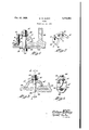
- Figure 1 is a vertical sectional view showing my fixture in clamping position.
- Figure 2 is a perspective View of the clamp fixture.
- Figure 3 is a view similar to Figure 1 showing a modified form of my invention.
- Figure 4 is a sectional view taken on line 4-4 of Figure 3.
- an angle clamp designated generally at 2 which is formed of a straight central section 4 and two diverging angular end portions 6 and 8, the latter being shorter than the former, and the tips of both ends being provided with transverse grooves or corrugations such as It to prevent slipping.
- the central portion 4 there is a circular opening l2, the diameter of which tapers from one face of the clamp to the other, the upper face being the 45 smaller diameter.
- a raised boss I4 Adjacent the end juncture of the end 6 and the central section there is provided a raised boss I4 on both the inner and outer surfaces, the same forming roughly a cylinder and internally thread- 50 ed as at I6 for a bolt [8 which would extend at substantially right angles to the central section 4.
- the thicknes of the lower portion of the I beam will 10 vary and the bolt it provides vertical adjustment of the other side of the clamp to keep the central portion substantially horizontal though this is not absolutely necessary as the tapered bolt hole l2 allows the bolt to pass through if the plate and central section i are not parallel.
- a notch is provided in the clamp 2 so that that one may be used for either type.
- the short leg 8' is designed to contact the I beam face and there is an eye hook 36 which extends down around the messenger cable 38 and has a threaded shank 40 which extends upwardly through the tapered opening I2 and is held in place by a washer 42 and nut M pulling the cable 38 up against the I beam lower surface and into the notch 34 in the clamp to thus support the cable from the beam for any period 35 desired.
- a central section having a tapered opening therein, a pair of arms extending at diverging angles from the central portion, the arms being of different lengths, the 45 ends thereof being curved and provided with corrugations and means extending through the tapered opening to clamp any desired part to the extending arms at any angle within a given range.
- a clamp having a central section with a tapered opening therein, angular arms extending from the central portion, said arms being of different lengths, the ends thereof being curved and provided with corrugations and means extending at any desired angle through the tapered opening to pull one of the members against the other and one arm, the other arm contacting the second member.
- a clamp comprising a straight central portion, angularly divergent arms extending therefrom, corrugations on the tips of the arms, and threaded means in one of the arms to vary the effective length of the arm for contacting one of the members.
Landscapes
- Engineering & Computer Science (AREA)
- Architecture (AREA)
- Physics & Mathematics (AREA)
- Electromagnetism (AREA)
- Civil Engineering (AREA)
- Structural Engineering (AREA)
- Clamps And Clips (AREA)
Description
Oct. 10, 1939.
W. W. BARCY CLAMP Filed Jan. 24, 1958 M I a [4 ,5 M I 12 i Q Y I A,
INVENTOR.
ATTORNEY.
Patented Oct. 10, 1939 CLAMP William Wilkins Barcy, Detroit, Mich., assignor to T. B. F. Company, Detroit, Mich.
Application January 24, 1938, Serial No. 186,525
3 Claims. (01. 189-35) This invention relates to a fixture and more specifically to a supporting fixture to temporarily assist in supporting during construction.
It is often necessary during the construction of buildings and particularly in instances of large factory buildings, that it is desirable and necessary to temporarily support from some structure already in place some apparatus to assist in holding members for further construction. Since it is only to be temporary it is desirable that it should not be necessary to drive holes in the structure such as steel I beams.
It is therefore the primary object of my invention to provide a fixture for securing to a stationary structure without altering the structure.
It is a further object of my invention to provide a fixture as set forth above which is capable of a plurality of uses or adaptations.
With the above and other objects in view, which will become apparent as the specification proceeds, my invention will be best understood by reference to the following specification and claims which constructions described therein are illustrated in the accompanying drawing, in which:
Figure 1 is a vertical sectional view showing my fixture in clamping position.
Figure 2 is a perspective View of the clamp fixture.
Figure 3 is a view similar to Figure 1 showing a modified form of my invention.
Figure 4 is a sectional view taken on line 4-4 of Figure 3.
Referring now specifically to the drawing and particularly to the species of invention shown in Figures 1 and 2, there is provided an angle clamp designated generally at 2 which is formed of a straight central section 4 and two diverging angular end portions 6 and 8, the latter being shorter than the former, and the tips of both ends being provided with transverse grooves or corrugations such as It to prevent slipping. In the central portion 4 there is a circular opening l2, the diameter of which tapers from one face of the clamp to the other, the upper face being the 45 smaller diameter.
Adjacent the end juncture of the end 6 and the central section there is provided a raised boss I4 on both the inner and outer surfaces, the same forming roughly a cylinder and internally thread- 50 ed as at I6 for a bolt [8 which would extend at substantially right angles to the central section 4.
In application let us assume that the construction of the building has reached the stage where 55 the structural I beams are in and one such as shown at 20 is selected. It is desired tosupport therefrom a plate or member 22 which has an opening 24 therein. A bolt 26 is inserted through the opening 24 and a washer 28 is provided under the bolt head. The shaft of the bolt extends through the tapered opening H2 in the clamp fixture and a washer 30 and clamping nut 32 are applied to the bolt and tightened down to clamp the plate to the I beam. In some instances the thicknes of the lower portion of the I beam will 10 vary and the bolt it provides vertical adjustment of the other side of the clamp to keep the central portion substantially horizontal though this is not absolutely necessary as the tapered bolt hole l2 allows the bolt to pass through if the plate and central section i are not parallel.
In the modified form shown in Figures 3 and 4, the use of the same type of clamp is shown when it is desired to support a messenger cable such as that used for supporting conduit for wiring purposes. In this case the adjusting bolt i8 is omitted and there is provided in the longer angular leg 6 a circular notch 34.
It should be noted in this respect that such a notch is provided in the clamp 2 so that that one may be used for either type. As before, the short leg 8' is designed to contact the I beam face and there is an eye hook 36 which extends down around the messenger cable 38 and has a threaded shank 40 which extends upwardly through the tapered opening I2 and is held in place by a washer 42 and nut M pulling the cable 38 up against the I beam lower surface and into the notch 34 in the clamp to thus support the cable from the beam for any period 35 desired.
It is obvious that when the purpose has been carried out the bolt 26 or hook 36 may be removed easily and the whole temporary means taken down and used again when desired.
I claim:
1. In a clamping fixture, a central section having a tapered opening therein, a pair of arms extending at diverging angles from the central portion, the arms being of different lengths, the 45 ends thereof being curved and provided with corrugations and means extending through the tapered opening to clamp any desired part to the extending arms at any angle within a given range.
2. In a clamping fixture for clamping two members together, a clamp having a central section with a tapered opening therein, angular arms extending from the central portion, said arms being of different lengths, the ends thereof being curved and provided with corrugations and means extending at any desired angle through the tapered opening to pull one of the members against the other and one arm, the other arm contacting the second member.
3. In a clamping device for holding two members together, a clamp comprising a straight central portion, angularly divergent arms extending therefrom, corrugations on the tips of the arms, and threaded means in one of the arms to vary the effective length of the arm for contacting one of the members.
WILLIAM WILKINS BARCY.
Priority Applications (1)
| Application Number | Priority Date | Filing Date | Title |
|---|---|---|---|
| US186525A US2175453A (en) | 1938-01-24 | 1938-01-24 | Clamp |
Applications Claiming Priority (1)
| Application Number | Priority Date | Filing Date | Title |
|---|---|---|---|
| US186525A US2175453A (en) | 1938-01-24 | 1938-01-24 | Clamp |
Publications (1)
| Publication Number | Publication Date |
|---|---|
| US2175453A true US2175453A (en) | 1939-10-10 |
Family
ID=22685294
Family Applications (1)
| Application Number | Title | Priority Date | Filing Date |
|---|---|---|---|
| US186525A Expired - Lifetime US2175453A (en) | 1938-01-24 | 1938-01-24 | Clamp |
Country Status (1)
| Country | Link |
|---|---|
| US (1) | US2175453A (en) |
Cited By (22)
| Publication number | Priority date | Publication date | Assignee | Title |
|---|---|---|---|---|
| US2467877A (en) * | 1946-05-22 | 1949-04-19 | Irving Subway Grating Co Inc | Fastening device |
| US2553950A (en) * | 1946-06-26 | 1951-05-22 | Snyder Jacob Rush | Fastening for rails |
| US2572432A (en) * | 1946-10-19 | 1951-10-23 | Beulah H Bates | Grating anchor |
| US2572431A (en) * | 1946-03-01 | 1951-10-23 | Beulah H Bates | Anchor for gratings |
| US2625357A (en) * | 1946-02-27 | 1953-01-13 | Earl B Atkinson | Bar hanger attachment |
| US2690877A (en) * | 1948-09-03 | 1954-10-05 | Snyder Jacob Rush | Fastening for railway rails |
| US2733034A (en) * | 1956-01-31 | Pipe hangers | ||
| US2782045A (en) * | 1954-01-04 | 1957-02-19 | Smashproof Company | Caster mounting for creepers and the like |
| US2820656A (en) * | 1953-07-14 | 1958-01-21 | Struers Chemiske Lab H | Device for the clamping together of two bars or tubes at an angle with one another |
| US4439900A (en) * | 1980-07-16 | 1984-04-03 | Burton Delingpole & Company Limited | Scaffolding devices |
| US5158392A (en) * | 1988-08-03 | 1992-10-27 | Hoshida Kogyo K.K. | Arrangement for mounting panel assemblies on a building |
| US5364203A (en) * | 1992-01-24 | 1994-11-15 | Mitsubishi Denki Kabushiki Kaisha | Bus bar connecting device |
| US5451116A (en) * | 1992-06-09 | 1995-09-19 | General Electric Company | Tripod plate for turbine flowpath |
| US20020182003A1 (en) * | 2001-04-12 | 2002-12-05 | Hans-Herlof Hardtke | Clamping device for clamping girders |
| ES2255370A1 (en) * | 2003-11-27 | 2006-06-16 | S.A. De Vera (Savera) | High-resistant sliding bridle for elevator guides, has jaws connected to baseplate and adjustable with respect to blades of elevator guide without applying excessive force on guide |
| EP1946891A1 (en) | 2007-01-16 | 2008-07-23 | Tyco European Metal Framing Limited | Clamp head |
| US20090208284A1 (en) * | 2008-02-19 | 2009-08-20 | Airbus Uk Limited | Clamped friction joint |
| EP2383475A2 (en) * | 2010-03-22 | 2011-11-02 | HILTI Aktiengesellschaft | Attachment device |
| US20120272607A1 (en) * | 2010-01-21 | 2012-11-01 | Paul Alan Cooper | Building frame |
| US20150252691A1 (en) * | 2014-03-05 | 2015-09-10 | MTU Aero Engines AG | Gas Turbine Duct Casing |
| US20150266165A1 (en) * | 2012-10-01 | 2015-09-24 | Ev Ip Lp | Clamp Head |
| US10451198B2 (en) * | 2017-06-19 | 2019-10-22 | Thomas & Betts International Llc | Cable tray hold-down clamp |
-
1938
- 1938-01-24 US US186525A patent/US2175453A/en not_active Expired - Lifetime
Cited By (28)
| Publication number | Priority date | Publication date | Assignee | Title |
|---|---|---|---|---|
| US2733034A (en) * | 1956-01-31 | Pipe hangers | ||
| US2625357A (en) * | 1946-02-27 | 1953-01-13 | Earl B Atkinson | Bar hanger attachment |
| US2572431A (en) * | 1946-03-01 | 1951-10-23 | Beulah H Bates | Anchor for gratings |
| US2467877A (en) * | 1946-05-22 | 1949-04-19 | Irving Subway Grating Co Inc | Fastening device |
| US2553950A (en) * | 1946-06-26 | 1951-05-22 | Snyder Jacob Rush | Fastening for rails |
| US2572432A (en) * | 1946-10-19 | 1951-10-23 | Beulah H Bates | Grating anchor |
| US2690877A (en) * | 1948-09-03 | 1954-10-05 | Snyder Jacob Rush | Fastening for railway rails |
| US2820656A (en) * | 1953-07-14 | 1958-01-21 | Struers Chemiske Lab H | Device for the clamping together of two bars or tubes at an angle with one another |
| US2782045A (en) * | 1954-01-04 | 1957-02-19 | Smashproof Company | Caster mounting for creepers and the like |
| US4439900A (en) * | 1980-07-16 | 1984-04-03 | Burton Delingpole & Company Limited | Scaffolding devices |
| US5158392A (en) * | 1988-08-03 | 1992-10-27 | Hoshida Kogyo K.K. | Arrangement for mounting panel assemblies on a building |
| US5364203A (en) * | 1992-01-24 | 1994-11-15 | Mitsubishi Denki Kabushiki Kaisha | Bus bar connecting device |
| US5451116A (en) * | 1992-06-09 | 1995-09-19 | General Electric Company | Tripod plate for turbine flowpath |
| US7021855B2 (en) * | 2001-04-12 | 2006-04-04 | Lisega Gmbh | Clamping device for clamping girders |
| US20020182003A1 (en) * | 2001-04-12 | 2002-12-05 | Hans-Herlof Hardtke | Clamping device for clamping girders |
| ES2255370A1 (en) * | 2003-11-27 | 2006-06-16 | S.A. De Vera (Savera) | High-resistant sliding bridle for elevator guides, has jaws connected to baseplate and adjustable with respect to blades of elevator guide without applying excessive force on guide |
| EP1946891A1 (en) | 2007-01-16 | 2008-07-23 | Tyco European Metal Framing Limited | Clamp head |
| US20090051093A1 (en) * | 2007-01-16 | 2009-02-26 | Tyco European Metal Framing Limited | Clamp head |
| US8459624B2 (en) * | 2007-01-16 | 2013-06-11 | Ev Ip Lp | Clamp head |
| US20090208284A1 (en) * | 2008-02-19 | 2009-08-20 | Airbus Uk Limited | Clamped friction joint |
| US20120272607A1 (en) * | 2010-01-21 | 2012-11-01 | Paul Alan Cooper | Building frame |
| US8931233B2 (en) * | 2010-01-21 | 2015-01-13 | Paul Alan Cooper | Building frame |
| EP2383475A2 (en) * | 2010-03-22 | 2011-11-02 | HILTI Aktiengesellschaft | Attachment device |
| US20150266165A1 (en) * | 2012-10-01 | 2015-09-24 | Ev Ip Lp | Clamp Head |
| US9597780B2 (en) * | 2012-10-01 | 2017-03-21 | Ev Ip Lp | Clamp head |
| US20150252691A1 (en) * | 2014-03-05 | 2015-09-10 | MTU Aero Engines AG | Gas Turbine Duct Casing |
| US9726042B2 (en) * | 2014-03-05 | 2017-08-08 | MTU Aero Engines AG | Gas turbine duct casing |
| US10451198B2 (en) * | 2017-06-19 | 2019-10-22 | Thomas & Betts International Llc | Cable tray hold-down clamp |
Similar Documents
| Publication | Publication Date | Title |
|---|---|---|
| US2175453A (en) | Clamp | |
| US2345650A (en) | Skeletonized structure | |
| US3469810A (en) | Beam clamp | |
| US1169635A (en) | Pipe-hanger. | |
| US3177542A (en) | Clamping device | |
| US3321161A (en) | Hanger clamp | |
| US4408940A (en) | Bolt anchor assembly | |
| US1976595A (en) | Hanger | |
| JPS5986782A (en) | Fixture | |
| US2616645A (en) | Pipe hanger | |
| US1114013A (en) | Concrete-insert. | |
| US2164846A (en) | Mounting device | |
| US2625357A (en) | Bar hanger attachment | |
| US2273571A (en) | Pipe hanger | |
| US3140848A (en) | Top beam clamp | |
| JPH0294206A (en) | Fitting structure for lighting fixture | |
| US1802995A (en) | Gain fixture for poles | |
| US2411678A (en) | Clamp and spacer for concrete forms | |
| US2504360A (en) | Clamp means | |
| FI76189B (en) | ANORDNING FOER FOERANKRING I BETONG. | |
| US1851292A (en) | Expansion bolt | |
| US2706499A (en) | Spacing and closure device for electrical conduits | |
| US9027208B1 (en) | Wire gripping assembly for drop wire support of electrical boxes or light fixtures | |
| US3058713A (en) | Hanger clamp | |
| US1218283A (en) | Hanger or clip for steel framework construction. |