US2156127A - Brake - Google Patents
Brake Download PDFInfo
- Publication number
- US2156127A US2156127A US106026A US10602636A US2156127A US 2156127 A US2156127 A US 2156127A US 106026 A US106026 A US 106026A US 10602636 A US10602636 A US 10602636A US 2156127 A US2156127 A US 2156127A
- Authority
- US
- United States
- Prior art keywords
- brakes
- lever
- plunger
- connection
- rod
- Prior art date
- Legal status (The legal status is an assumption and is not a legal conclusion. Google has not performed a legal analysis and makes no representation as to the accuracy of the status listed.)
- Expired - Lifetime
Links
Images
Classifications
-
- B—PERFORMING OPERATIONS; TRANSPORTING
- B60—VEHICLES IN GENERAL
- B60T—VEHICLE BRAKE CONTROL SYSTEMS OR PARTS THEREOF; BRAKE CONTROL SYSTEMS OR PARTS THEREOF, IN GENERAL; ARRANGEMENT OF BRAKING ELEMENTS ON VEHICLES IN GENERAL; PORTABLE DEVICES FOR PREVENTING UNWANTED MOVEMENT OF VEHICLES; VEHICLE MODIFICATIONS TO FACILITATE COOLING OF BRAKES
- B60T8/00—Arrangements for adjusting wheel-braking force to meet varying vehicular or ground-surface conditions, e.g. limiting or varying distribution of braking force
- B60T8/26—Arrangements for adjusting wheel-braking force to meet varying vehicular or ground-surface conditions, e.g. limiting or varying distribution of braking force characterised by producing differential braking between front and rear wheels
-
- Y—GENERAL TAGGING OF NEW TECHNOLOGICAL DEVELOPMENTS; GENERAL TAGGING OF CROSS-SECTIONAL TECHNOLOGIES SPANNING OVER SEVERAL SECTIONS OF THE IPC; TECHNICAL SUBJECTS COVERED BY FORMER USPC CROSS-REFERENCE ART COLLECTIONS [XRACs] AND DIGESTS
- Y10—TECHNICAL SUBJECTS COVERED BY FORMER USPC
- Y10T—TECHNICAL SUBJECTS COVERED BY FORMER US CLASSIFICATION
- Y10T74/00—Machine element or mechanism
- Y10T74/20—Control lever and linkage systems
- Y10T74/20558—Variable output force
Definitions
- This invention relates 'to brakes and more particularly to a method of and apparatus for varying the ratio of the applying force between the front brakes of a vehicle and the rear brakes 5 thereof.
- the limits above sults are determined by the shifting of the weight of the vehicle from the rear to the front wheels, caused by inertia forces during deceleration.
- Another object is to provide Aoperating means for y'the rear wheel brakes of a vehicle in which increasingr force in a driver operated connection applies the brakes up to a predetermined limit and then releases them crease in force beyond
- One desirable means ing that at which itis desirable to have equalized brakes. Until this means yields, the two connections, the lever and its fulcrurn move together in the same direction. .
- said -meaxni additional which unstable vbraking reate the front' brakes lll.
- Figure V1 is a partially diagrammatic view of a four wheel brake system embodying my invention.
- Figure 2 is a longitudinal vertical section through one form of my novel control device.V
- the system of Figure 1 comprises a set of vfront brakes I 0 and a set of rear brakes I2.
- a pedal I4 and a hand lever I6 are provided for alternative operation of the brakes. Both are con-V nected by ilexible cables I8 to arms' 20 rigidly secured to a cross-shaft 22 journaled in brackets xed to the vehicle chassis.
- a cross-arm 24 secured at its center to the cross-shaft has a ilexible cable 2t. secured to 25 its lower end and extending forwardly to operons to these brakesmay include a pair of cables 2l extendfrom the brake chambers to a point adjacent the center line of the vehicle where they are secured to opposite ends of a cross-arm l0 fixed on a vertical shaft 32.
- the shaft 32 has another arm 3 4 to which 'the forward end of the cable 26 is secured.
- a link 36 pivoted on thefront axle 38 provides a 35 transversely movable bearing 'for the shaft I2 to equalize .the forces applied to each of the front brakes.
- a rod 40 extends toward the rear oi.' the vehicle from theupper end of the cross-arm 24 40 and is secured to my novel control device 42 (to be fully described with reference to Figure 2) andi.v rod 44 extends from the control device to operate the rear brakes ⁇ I2.
- the rear brakes are provided with transversely extending cables '48 connected to opposite ends of a cross-arm 48 or a vertical shaft 50 which has another arm 52 to which is secured the rod 44.
- the v'shaft is mounted similarly to the shaft 32 --on a link 54. 50
- the rod 40 is shown connected to a lever 56 ⁇ fulcrumed between its ends on a pin 58 secured in a plunger made up of 62 adjustably threaded together. ably mounted in a bracket 64 secured to the chassis frame (not shown), while the part 62 is slidably mounted in a housing 66 which in turn slides in a sleeve 68 also s ecured'to the chassis frame.
- a coiled compression spring 16 is mounted in an annular space between the housing 66 and the plunger part 62 and has its forward end bearing against the housing and its rear end bearing on a washer 12 seated against a shoulder formed on the plunger part.
- a shoulder on the part 66 prevents relative movement of the part 62 and the housing 66 in the direction in which they are urged by the spring 16.
- the housing 66 is provided with a projection 14 forming a bearing in which the rod 44 slides. Between this projection and a shoulder 16 formed on the rod 44 adjacent 56, is a second spring 18 which may be identical with the spring 16. Jam nuts 66 adjustably positioned on the rod 44 provide a stop preventing relative movement between the rod and the prounder the influence of the spring 18.
- the rear end 82 of the rod is formed in a generally conical shape and seated thereon are a plurality of rolls 64 projecting through slots 86 in the out of contact with the chassis mounted sleeve 68.
- a plug 86 ⁇ closes the end of the housing 66 but permits access to the end of the plunger part 62 which may be provided with a non-circular recess (not shown) adapted to receive an adjusting tool.
- the plunger 68--62 will move forwardly relatively to the housing 66, and the conical end 62 willforce the rolls 84 outwardly against the sleeve 68, locking the plunger to the sleeve.
- a .vehicle brake control device comprising a plunger axially slidable in a sleeve fixed to the vehicle chassis, a lever pivoted between its ends on the plunger, a driver operated connection on one end of the lever, a brake operating connection on lthe other end of the lever, a housing axially l slidable on thev plunger, opposed compressionsprings effectively interposed between the plunger and the housing, and the housing and said other end of thel lever, and means for locking the plunger in the sleeve when the springs are compressed.
- a vehicle brake control device adapted to be mounted on a vehicle chassis and comprising an axially movable plunger, a lever pivoted between its ends on the plunger, a driver operated connection on one end of the lever, a brake operating connection on the other end of the lever, spring means preventing rotation of the lever about its pivot until a predetermined force is exerted by said driver operated connection, and means for locking the plunger when said predetermined'force is exceeded, said locking means for movingvthe rolls relatively to the plunger to cause the conical end to engage them with a part of the chassis.
- a four wheel braking system comprising a driver operated member, a rigid connection from said member to the front brakes, an axially movable plunger, a lever pivoted between its ends on said plunger, a connection from the driver operated member to one end of said lever, a connection from the other end of the lever to the rear brakes, yieldable means preventing rotation of the lever until a predetermined force lis exceeded, and means for locking the plunger when said predeterminediorce is exceeded.
- a vehicle having brakes and an applying member having connections extending to said brakes and having a fixed member rigid with the chassis frame, one of said connections including a locking device operated upon a predetermined force being applied to said connection to lock a part of the connection to said fixed member and also including means actuated when said device is locked for changing the force applied through said connection to its brakes.
- a vehicle having brakes and an .applying member having connections extending to said brakes, one of said connections including a locksaid connection and also includsaid device is locked for reducing the force applied through said connection to its brakes and thereby partially releasing said brakes.
Landscapes
- Engineering & Computer Science (AREA)
- Transportation (AREA)
- Mechanical Engineering (AREA)
- Regulating Braking Force (AREA)
Description
April 25, 1939. G. ROBERTS 2,156,127
BRAKE Filed Oct. 16, 1936 (ya E z @Mii/fi INVENTOR m @152mg ATTORNF" Patented Apr. 25, v1193i PATENT oFFlcE BRAKE Glyn Pierce' Roberts,
England, as-
lignor to Bendix Products Corporation, South Bend, Ind.,
Application 'October a corporation' of In 1s, 1936, semi No.
In Great Britain Octber 18, 1935 5 Claims. (Cl. 188-10) This invention relates 'to brakes and more particularly to a method of and apparatus for varying the ratio of the applying force between the front brakes of a vehicle and the rear brakes 5 thereof. l
It has long been recognized as desirable to divide the braking load of a vehicle equipped with four wheel\brakes equally between the front and rear brakes, as such a systemV gives very stable braking below certain limits and results in even brake lining wear.
.The limits above sults are determined by the shifting of the weight of the vehicle from the rear to the front wheels, caused by inertia forces during deceleration.
"I'his shifting of weight reduces the availablel traction4 of the rearwheels and consequently, with equalized brakes, the rear wheels slide whenever the braking eiort equals the available traction.
In order to minimize this di'iiiculty mechanical brakes are often arbitrarily set so that the front brakes exert a. larger proportion of braking eifort at all times, while hydraulic brakes are sometimes built with smaller wheel cylinders in the rear for a similar purpose.
Inasmuch as a large proportion, often more than 80%, of the use of vehicle brakes occurs when the braking efl'ort is less than the limit above which equalized brakes would permit the rear wheelsto slide, it is an object of my invention to provide a method of and apparatus' for applying four wheel brakes equally until a .certain braking eilort is obtained and thereafter to wheels.
Another object is to provide Aoperating means for y'the rear wheel brakes of a vehicle in which increasingr force in a driver operated connection applies the brakes up to a predetermined limit and then releases them crease in force beyond One desirable means ing that at which itis desirable to have equalized brakes. Until this means yields, the two connections, the lever and its fulcrurn move together in the same direction. .Upon the yielding oi' said -meaxni additional which unstable vbraking reate the front' brakes lll. Connecti proportion the eilort between the front and rear in proportion to the inmeans acts to lock the fulcrum againstfurther movement, and thereafter the lever rotates on the 'fulcrum movingthe connection to the rear brakes in thel opposite direction and ,thus partially releasing them in proportion to the continued move- 5 ment of the driver Aoperated connection.v
Other objects and desirable particular constructionswill become apparent upon reference to Athe following detailed description of an illustrative embodiment oi' my invention shown in 10 the accompanying drawing, in which:
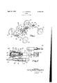
Figure V1 is a partially diagrammatic view of a four wheel brake system embodying my invention; and
Figure 2 is a longitudinal vertical section through one form of my novel control device.V
The system of Figure 1 comprises a set of vfront brakes I 0 and a set of rear brakes I2. A pedal I4 and a hand lever I6 are provided for alternative operation of the brakes. Both are con-V nected by ilexible cables I8 to arms' 20 rigidly secured to a cross-shaft 22 journaled in brackets xed to the vehicle chassis. x
A cross-arm 24 secured at its center to the cross-shaft has a ilexible cable 2t. secured to 25 its lower end and extending forwardly to operons to these brakesmay include a pair of cables 2l extendfrom the brake chambers to a point adjacent the center line of the vehicle where they are secured to opposite ends of a cross-arm l0 fixed on a vertical shaft 32.
The shaft 32 has another arm 3 4 to which 'the forward end of the cable 26 is secured. A link 36 pivoted on thefront axle 38 provides a 35 transversely movable bearing 'for the shaft I2 to equalize .the forces applied to each of the front brakes.
A rod 40 extends toward the rear oi.' the vehicle from theupper end of the cross-arm 24 40 and is secured to my novel control device 42 (to be fully described with reference to Figure 2) andi.v rod 44 extends from the control device to operate the rear brakes `I2. The rear brakes are provided with transversely extending cables '48 connected to opposite ends of a cross-arm 48 or a vertical shaft 50 which has another arm 52 to which is secured the rod 44. The v'shaft is mounted similarly to the shaft 32 --on a link 54. 50
.type of hookup It is to be" understood that any accomplishing substantially the same purpose as the above might be employed; as determined by the type of brakes used, the construction of the chassis frame, and the disposition of other meu two parts 66 and 'Ihe forward-end of the part 60 is slidhousing 66 and just -jection 14 given movement of the chanical units thereon, such as the engine, transmission, etc.
Referring now to Figure 2 the rod 40 is shown connected to a lever 56 `fulcrumed between its ends on a pin 58 secured in a plunger made up of 62 adjustably threaded together. ably mounted in a bracket 64 secured to the chassis frame (not shown), While the part 62 is slidably mounted in a housing 66 which in turn slides in a sleeve 68 also s ecured'to the chassis frame.
A coiled compression spring 16 is mounted in an annular space between the housing 66 and the plunger part 62 and has its forward end bearing against the housing and its rear end bearing on a washer 12 seated against a shoulder formed on the plunger part. A shoulder on the part 66 prevents relative movement of the part 62 and the housing 66 in the direction in which they are urged by the spring 16.
The housing 66 is provided with a projection 14 forming a bearing in which the rod 44 slides. Between this projection and a shoulder 16 formed on the rod 44 adjacent 56, is a second spring 18 which may be identical with the spring 16. Jam nuts 66 adjustably positioned on the rod 44 provide a stop preventing relative movement between the rod and the prounder the influence of the spring 18.
The rear end 82 of the rod is formed in a generally conical shape and seated thereon are a plurality of rolls 64 projecting through slots 86 in the out of contact with the chassis mounted sleeve 68.
A plug 86` closes the end of the housing 66 but permits access to the end of the plunger part 62 which may be provided with a non-circular recess (not shown) adapted to receive an adjusting tool.
In operation, movement of either the pedal 'I4 or the lever I6 rotates the cross-shaft 22 applylng the front brakes through the cable 26 and moving the rod 46 forwardly. Both o f the springs 10 and 18 are provided with a predetermined initial tension which prevents relative movement between the lever 56 and the part 66 and between the housing 66 and plunger 62-60 and consequently all these parts are translated forwardly as a unit, sliding in the bracket 64 and the sleeve 66, and drawing the rod 44 forI wardly to apply the rear brakes.
If, however, the applying force exceeds the initial force ofthe springs, the plunger 68--62 will move forwardly relatively to the housing 66, and the conical end 62 willforce the rolls 84 outwardly against the sleeve 68, locking the plunger to the sleeve.
Thereafter continued movement of the rod 40 forwardly rocks the lever 56 about the fulcrum pin 56 and moves the rod 44 rearwardly, compressing the spring 16, and releasing the rear bglsies in prop rtion to the movement of the r The distances between the fulcrum pin 66 may give any desired relief to the rear brakes for a rod 46.
Thus it will be seen that'my invention provides equal action for all four brakes until a predetermined braking forceis exerted on the the rods 44 and 46 and its connection to the lever be so proportioned to connections, and that thereafter additional force is applied only to the front brakes while the rear brakes are relieved in any'desired proportion.
While only one embodiment of my invention has been described in detail, it is to be understood that various modiiications of form and arrangement might be made within the scope and spirit of'the inventive idea, and consequently I do not intend to be limited by that embodiment or otherwise than by the terms of the appended claims.
What is claimed is:
l. A .vehicle brake control device comprising a plunger axially slidable in a sleeve fixed to the vehicle chassis, a lever pivoted between its ends on the plunger, a driver operated connection on one end of the lever, a brake operating connection on lthe other end of the lever, a housing axially l slidable on thev plunger, opposed compressionsprings effectively interposed between the plunger and the housing, and the housing and said other end of thel lever, and means for locking the plunger in the sleeve when the springs are compressed.
2. A vehicle brake control device adapted to be mounted on a vehicle chassis and comprising an axially movable plunger, a lever pivoted between its ends on the plunger, a driver operated connection on one end of the lever, a brake operating connection on the other end of the lever, spring means preventing rotation of the lever about its pivot until a predetermined force is exerted by said driver operated connection, and means for locking the plunger when said predetermined'force is exceeded, said locking means for movingvthe rolls relatively to the plunger to cause the conical end to engage them with a part of the chassis.
3. A four wheel braking system comprising a driver operated member, a rigid connection from said member to the front brakes, an axially movable plunger, a lever pivoted between its ends on said plunger, a connection from the driver operated member to one end of said lever, a connection from the other end of the lever to the rear brakes, yieldable means preventing rotation of the lever until a predetermined force lis exceeded, and means for locking the plunger when said predeterminediorce is exceeded.
4 A vehicle having brakes and an applying member having connections extending to said brakes and having a fixed member rigid with the chassis frame, one of said connections including a locking device operated upon a predetermined force being applied to said connection to lock a part of the connection to said fixed member and also including means actuated when said device is locked for changing the force applied through said connection to its brakes.
5. A vehicle having brakes and an .applying member having connections extending to said brakes, one of said connections including a locksaid connection and also includsaid device is locked for reducing the force applied through said connection to its brakes and thereby partially releasing said brakes.
GLYN Pnsxar:V nonna'rs. l
Applications Claiming Priority (1)
| Application Number | Priority Date | Filing Date | Title |
|---|---|---|---|
| GB2156127X | 1935-10-18 |
Publications (1)
| Publication Number | Publication Date |
|---|---|
| US2156127A true US2156127A (en) | 1939-04-25 |
Family
ID=10899972
Family Applications (1)
| Application Number | Title | Priority Date | Filing Date |
|---|---|---|---|
| US106026A Expired - Lifetime US2156127A (en) | 1935-10-18 | 1936-10-16 | Brake |
Country Status (1)
| Country | Link |
|---|---|
| US (1) | US2156127A (en) |
Cited By (3)
| Publication number | Priority date | Publication date | Assignee | Title |
|---|---|---|---|---|
| US2670057A (en) * | 1950-08-15 | 1954-02-23 | Austin Motor Co Ltd | Hydromechanical braking system for road vehicles |
| US2848903A (en) * | 1952-10-28 | 1958-08-26 | Trombetta Panfilo | Solenoid actuated operator system |
| US3576140A (en) * | 1969-06-11 | 1971-04-27 | Singer Co | Variable throttle controls |
-
1936
- 1936-10-16 US US106026A patent/US2156127A/en not_active Expired - Lifetime
Cited By (3)
| Publication number | Priority date | Publication date | Assignee | Title |
|---|---|---|---|---|
| US2670057A (en) * | 1950-08-15 | 1954-02-23 | Austin Motor Co Ltd | Hydromechanical braking system for road vehicles |
| US2848903A (en) * | 1952-10-28 | 1958-08-26 | Trombetta Panfilo | Solenoid actuated operator system |
| US3576140A (en) * | 1969-06-11 | 1971-04-27 | Singer Co | Variable throttle controls |
Similar Documents
| Publication | Publication Date | Title |
|---|---|---|
| US2884803A (en) | Force applying lever and linkage system | |
| US4386537A (en) | Variable ratio brake pedal | |
| GB1390999A (en) | Mechanical braking system for a vehicle trailer | |
| US3137370A (en) | Vehicle brake control and balancing system | |
| US2156127A (en) | Brake | |
| US3379479A (en) | Dynamic pressure converter, especially applicable to the braking system of an automobile vehicle | |
| US2779443A (en) | Automatic braking trailer hitch | |
| US3647032A (en) | Surge brake control | |
| US1954534A (en) | Brake | |
| US1969872A (en) | Equalizer for hydraulic brakes | |
| US1547133A (en) | Operating mechanism | |
| US2160071A (en) | Brake | |
| US2183283A (en) | Control means of land vehicles | |
| US2116882A (en) | Brake system for motor vehicles | |
| US2401084A (en) | Trailer hitch and automatic brake actuator | |
| US3371487A (en) | Divided master cylinder | |
| US1722233A (en) | Wheel brake for vehicles | |
| GB951393A (en) | Trailer brake actuator | |
| US2953412A (en) | Booster brake mechanism with anti skid control | |
| US2105299A (en) | Brake | |
| US2670057A (en) | Hydromechanical braking system for road vehicles | |
| US2214778A (en) | Locking device | |
| GB513957A (en) | Improvements in or relating to brakes for vehicles | |
| US2900054A (en) | Multiple ratio brake pedal construction | |
| US2063618A (en) | Braking apparatus |