US2104323A - Portable drilling rig - Google Patents
Portable drilling rig Download PDFInfo
- Publication number
- US2104323A US2104323A US740380A US74038034A US2104323A US 2104323 A US2104323 A US 2104323A US 740380 A US740380 A US 740380A US 74038034 A US74038034 A US 74038034A US 2104323 A US2104323 A US 2104323A
- Authority
- US
- United States
- Prior art keywords
- frame
- chassis
- drilling rig
- shaped
- drilling
- Prior art date
- Legal status (The legal status is an assumption and is not a legal conclusion. Google has not performed a legal analysis and makes no representation as to the accuracy of the status listed.)
- Expired - Lifetime
Links
- 238000005553 drilling Methods 0.000 title description 44
- 230000008093 supporting effect Effects 0.000 description 28
- 238000010276 construction Methods 0.000 description 4
- 239000011435 rock Substances 0.000 description 4
- 241000270295 Serpentes Species 0.000 description 3
- 238000004873 anchoring Methods 0.000 description 2
- 210000000481 breast Anatomy 0.000 description 1
- 230000001105 regulatory effect Effects 0.000 description 1
Images


Classifications
-
- E—FIXED CONSTRUCTIONS
- E21—EARTH OR ROCK DRILLING; MINING
- E21B—EARTH OR ROCK DRILLING; OBTAINING OIL, GAS, WATER, SOLUBLE OR MELTABLE MATERIALS OR A SLURRY OF MINERALS FROM WELLS
- E21B7/00—Special methods or apparatus for drilling
- E21B7/02—Drilling rigs characterised by means for land transport with their own drive, e.g. skid mounting or wheel mounting
- E21B7/025—Rock drills, i.e. jumbo drills
Definitions
- This invention relates to portable drillingvrigs and more particularly to supporting rigs for percussive tools of such type as are commonly known as wagon drills.
- An object of the present invention is to provide a drilling rig or wagon drill which is simple in construction, relatively light in weight and when equipped with a pneumatic or percussive tool may be moved from place to place by one man and which is so constructed that many different adjusted positions of the tool may be had, for various types and kinds of drilling operations. More specifically, an object "of the invention is to provide a one-man wagon drill rig for use in various types of drilling with pneumatic drills of the hammer piston type.
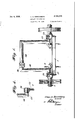
- Fig. 1 is a front elevation of the improved drilling rig.
- Fig. 2 is a side elevation of the drilling rig.
- Fig. 3 is a top plan of the improved drilling rig.
- Fig. 4 is a section on the line 4-4 of Fig. 3.
- Figures 5 to 13 inclusive are views in side elevation, front elevation and top plan showing various positions and adjustments of the improved drilling rig, for drilling various types of holes.
- the improved one-man portable drilling rig comprises a substantially U-shaped chassis I which has axial spindles 2 securely attached in any suitable manner such as by detachable brackets 3 to the legs of the chassis I adjacent to their ends as clearly shown in Fig. 3 of the drawings.
- a suitable cross-brace 4 is provided intermediate the ends of the legs of the chassis I and the cross-bar or loop 5 thereof.
- a handle 6 is connected to the cross-bar or loop 5 of the chassis to facilitate the movement of the rig from one place to another by a man.
- Anchoring pins 1 are adjustably carried by the chassis I adjacent to the loop or crossbar 5 and they are clamped in adjusted positions by the tightening of the nuts 8 on the threaded stems 8 of the anchor-bar carrying members III. The tightening of the nuts 8 on the threaded stems 8 clamp the anchor bars 1 against the stationary members II which are secured to the chassis I.
- the bearings I2 receive the spindle ends ll of the substantially U-shaped tool-carrying frame I8.
- the tool-carrying frame I8 has a bracket I9 adjustably mounted upon the crossbar 28 thereof so that a percussive tool (not shown) carried by the bracket I9 may be adjusted in the same horizontal plane laterally along the cross-bar 20 for the purpose of drilling a series of holes alongside of each other.
- the frame I8 is, of course, through the medium of the bearings I2, pivotally supported by the chassis I and it may be moved into any desired position or angle with respect to the horizontal to vary the elevation of the drill or pneumatic tool carried by the bracket I8 for drilling horizontal holes at various elevations or at various angles with respect to the horizontal or the-perpendicular. Also, by the particular construction of the drill rig, the frame I8 may be lowered sufliciently that holes may be drilled horizontally or at slight angles to the horizontal in planes below the plane of the axis of the axial spindles 2.
- the various Figures 5 to 13 illustrate positions and adjustments of the substantially U-shaped drill carrying frame I8 showing the flexibility of adjustment of the drilling rig for various types of drilling. 5
- Figure 5 shows the U-shaped supporting frame I8 positioned perpendicularly with respect to the horizontal carrying frame I with the drill indicated at A positioned vertically for down hole drilling.
- Figure 6 is a front elevation of the drilling rig adjusted as shown in Figure 5 and the dot-anddash lines B indicate lateral angles at which the drill A may be adjusted for drilling a plurality of holes from a single setting of the drill rig.
- FIG 7 the substantially U-shaped carrying frame I8 is shown as tilted to the rear from the supporting wheels of the drill rig with the drill A positioned vertically for down hole drilln
- Figures 8 and 9 show a side elevation and a front elevation respectively of the portable drilling rig adjusted to permit line drilling.
- the supporting frame I8 is tilted forwardly so that the drill holes will be drilled forwardly of the wheels of the rig.
- the drill A is moved longitudinally along the cross bar 20 of the frame I8 as indicated by the dot-and-dash lines C.
- FIGs 10 and 11 the drill carrying frame is shown as adjusted for breast; drilling and while in these figures the frame I8 is shown perpendicular, to position the drill A at the highest elevation above the horizontally supporting frame i it is to be understood that by tilting the frame 18 at various angles the distance of the drill holes above the frame I may be varied or regulated as desired.
- One of such positions is shown in dotted lines in Figure 10 of the drawings, while various angular positions of the drill, horizontally is indicated by the dot-and-dash lines D in Figure 11.
- Figures 12 and 13 illustrate adjustment of the drilling rig for snake holing.
- the frame l8 and the drill A are shown in adjusted positions to permit snake holing or side hill drilling at positions above the frame i and the axis of the supporting wheels of the drill rig.
- a portable drilling rig the combination, of a chassis, wheels at one end of the chassis, a handle at the other end of the chassis, clamping bearings carried by said chassis, a substantially U-shaped tool-supporting frame, spindles on said frame engaging in said bearings for connecting the frame to the chassis to permit pivotal movement in an arc of approximately 180 of the frame about a horizontal axis means cooperating with said bearings for holding said frame in adjusted positions, a tool-supporting bracket adjustably carried by the cross-bar of said U-shaped supporting frame, and anchoring pins adjustably carried by said chassis adjacent to said handle.
- a chassis wheels at one end of the chassis, clamping bearings carried by the chassis, a substantially U-shaped tool-supporting frame, spindles on said frame engaging in said bearings for connecting the frame to the chassis to permit pivotal movement of the frame about a horizontal axis, and a tool supporting bracket adjustably carried by the cross bar of said U-shaped supporting frame.
- a portable drilling rig the combination, of a chassis, wheels at one end of the chassis, clamping bearings carried by said chassis, a substantially U-shaped tool-supporting frame, spindles on said frame engaging in said bearings for connecting the frame to the chassis to permit pivotal movement of the frame about a horizontal axis, a rock drilling mechanism, means pivotally and adjustably connecting said rock drilling mechanism intermediate its ends to the portion of the U-shaped supporting frame which is parallel to its pivotal axis, whereby the drilling mechanism is adjustable longitudinally of the drilling rig by pivotal movement of the U-shaped supporting frame and is pivotally adjustable on an axis transversely of the axis of the U-shaped supporting frame.
- a chassis wheels at one end of the chassis, clamping bearings carried by the chassis, a substantially U-shaped tool-supporting frame, spindies on said frame engaging in said bearings for connecting the frame to the chassis to permit pivotal movement of the frame about a horizontal axis, and a tool supporting bracket adjustably carried by the cross bar of said U-shaped supporting frame, said bracket constructed and arranged to permit pivotal movement of a rockdrilling mechanism carried thereby about axes parallel to and transversely of the pivotal axis of the U-shaped supporting frame.
- a chassis wheels at one end of the chassis, clamping bearings carried by the chassis, a substantially U-shaped tool-supporting frame, spindles on said frame engaging in said bearings for connecting the frame to the chassis to permit pivotal movement of the frame about a horizontal axis
- a tool supporting bracket adjustably carried by the cross bar of said U-shaped supporting frame, said bracket adjustable along the portion of said U-shaped frame parallel to its pivotal axis, said bracket constructed and arranged to permit pivotal movement of a tool carried thereby about axes parallel to and transversely of the pivotal axis of the U-shaped supporting frame.
- a chassis wheels at one end of the chassis, clamping bearings carried by the chassis, a substantially U-shaped tool-supporting frame, spindles on said frame engaging in said bearings for connecting the frame to the chassis to permit pivotal movement of the frame about a horizontal axis, and a tool supporting bracket adjustably carried by the cross bar of said U-shaped supporting frame, and means cooperating with said bearings for holding said tool-supporting frame in adjusted positions.
- a portable drilling rig the combination, of a chassis, wheels at one end of the chassis, clamping bearings carried by the chassis, a substantially U-shaped tool-supporting frame, spindles on said frame engaging in said bearings for connecting the frame to the chassis to permit pivotal movement of the frame about a horizontal axis, a tool supporting bracket adjustably carried by the cross bar of said U-shaped support ing frame, said bracket adjustable along the portion of said U-shaped frame parallel to its pivotal axis, said bracket constructed and arranged to permit pivotal movement of a tool carried thereby about axes parallel to and transversely of the pivotal axis of the .U-shaped supporting frame, and means cooperating with said bearings for holding said tool-supporting frame in adjusted positions.
- a chassis having one end open, wheels on the chassis at said open end, a substantially U- shaped tool-supporting frame, bearings for said supporting frame carried by said chassis inwardly of said open end and having their axes in a horizontal plane spaced from the horizontal plane of the axes of said wheels, spindles on said U-shaped frame and engaging said bearings for .pivotally connecting the U-shaped frame to the 10 U-shaped frame in adjusted positions, a tool supporting bracket adjustabiy carried by the crossbar of said U-shaped supporting frame, a rock drilling mechanism carried by said bracket, said bracket constructed and arranged to permit pivotal movement of the rock drilling mechanism carried thereby about axes parallel to and transversely of the pivotal axis of the U-shaped supporting frame.
Landscapes
- Life Sciences & Earth Sciences (AREA)
- Engineering & Computer Science (AREA)
- Geology (AREA)
- Mining & Mineral Resources (AREA)
- Physics & Mathematics (AREA)
- Environmental & Geological Engineering (AREA)
- Fluid Mechanics (AREA)
- General Life Sciences & Earth Sciences (AREA)
- Geochemistry & Mineralogy (AREA)
- Earth Drilling (AREA)
Description
Jan. 4, 1938. 'c. A. HlRSCHBERG 2,104,323
PORTABLE DRILLING RIG Ill INVENTOR BY M A TTORNEY Jan. 4, 1938. c. A. HIRSCHBERG 2,104,323
PORTABLE DRILLING RIG I Filed Aug. 18, 1934 3 Sheets-Sheet 2 .9 4 l j {I 16 10 3 INVENTOR BY A ORNEY ch Amm'lwer Jan. 4, 1938. c. A. HIRSCHBERG 2,104,323
PORTABLE DRILLING RIG Filed Aug. 18, 1934 3 Sheets-Sheet 3 INVENTOR BY M A TTORNEY CHARLES P). HIRSCHBEKG- n Patented Jan. 4, 1938 2.10am ron'rma DRILLING mo Charles A.
Hirsohberg, Mountain Lakes, N. 1.,
assignor to Worthington Pump and Machinery Corporation, New York, N. ,Y.,
of Virginia a corporation Application August is, 1934, Serial No. 740,880
8Glaiml.
This invention relates to portable drillingvrigs and more particularly to supporting rigs for percussive tools of such type as are commonly known as wagon drills.
An object of the present invention is to provide a drilling rig or wagon drill which is simple in construction, relatively light in weight and when equipped with a pneumatic or percussive tool may be moved from place to place by one man and which is so constructed that many different adjusted positions of the tool may be had, for various types and kinds of drilling operations. More specifically, an object "of the invention is to provide a one-man wagon drill rig for use in various types of drilling with pneumatic drills of the hammer piston type.
With these and other objects in view, as may appear from the accompanying specification, the invention consists of various features of construction and combination of parts, which will be first described in connection with the accompanying drawings, showing a portable drilling rig of the preferred form, and the features forming the invention will be specifically pointed out in the claims.
In the drawings:
Fig. 1 is a front elevation of the improved drilling rig.
Fig. 2 is a side elevation of the drilling rig.
Fig. 3 is a top plan of the improved drilling rig.
Fig. 4 is a section on the line 4-4 of Fig. 3.
Figures 5 to 13 inclusive are views in side elevation, front elevation and top plan showing various positions and adjustments of the improved drilling rig, for drilling various types of holes.
Referring more particularly to the drawings, the improved one-man portable drilling rig comprises a substantially U-shaped chassis I which has axial spindles 2 securely attached in any suitable manner such as by detachable brackets 3 to the legs of the chassis I adjacent to their ends as clearly shown in Fig. 3 of the drawings. A suitable cross-brace 4 is provided intermediate the ends of the legs of the chassis I and the cross-bar or loop 5 thereof. A handle 6 is connected to the cross-bar or loop 5 of the chassis to facilitate the movement of the rig from one place to another by a man. Anchoring pins 1 are adjustably carried by the chassis I adjacent to the loop or crossbar 5 and they are clamped in adjusted positions by the tightening of the nuts 8 on the threaded stems 8 of the anchor-bar carrying members III. The tightening of the nuts 8 on the threaded stems 8 clamp the anchor bars 1 against the stationary members II which are secured to the chassis I.
Intermediate the ends of the legs of the chassis I are located a pair of bearing structures I2 which are disposed directly opposite to each other and 5 comprise the sections I3 which are attached to the chassis, and the caps it which are attached to the sections I3 by means of the bolts I5 and nuts IS. The bearings I2 receive the spindle ends ll of the substantially U-shaped tool-carrying frame I8. The tool-carrying frame I8 has a bracket I9 adjustably mounted upon the crossbar 28 thereof so that a percussive tool (not shown) carried by the bracket I9 may be adjusted in the same horizontal plane laterally along the cross-bar 20 for the purpose of drilling a series of holes alongside of each other. The frame I8 is, of course, through the medium of the bearings I2, pivotally supported by the chassis I and it may be moved into any desired position or angle with respect to the horizontal to vary the elevation of the drill or pneumatic tool carried by the bracket I8 for drilling horizontal holes at various elevations or at various angles with respect to the horizontal or the-perpendicular. Also, by the particular construction of the drill rig, the frame I8 may be lowered sufliciently that holes may be drilled horizontally or at slight angles to the horizontal in planes below the plane of the axis of the axial spindles 2.
The various Figures 5 to 13 illustrate positions and adjustments of the substantially U-shaped drill carrying frame I8 showing the flexibility of adjustment of the drilling rig for various types of drilling. 5
Figure 5 shows the U-shaped supporting frame I8 positioned perpendicularly with respect to the horizontal carrying frame I with the drill indicated at A positioned vertically for down hole drilling.
Figure 6 is a front elevation of the drilling rig adjusted as shown in Figure 5 and the dot-anddash lines B indicate lateral angles at which the drill A may be adjusted for drilling a plurality of holes from a single setting of the drill rig.
In Figure 7 the substantially U-shaped carrying frame I8 is shown as tilted to the rear from the supporting wheels of the drill rig with the drill A positioned vertically for down hole drilln Figures 8 and 9 show a side elevation and a front elevation respectively of the portable drilling rig adjusted to permit line drilling. In this type of drilling the supporting frame I8 is tilted forwardly so that the drill holes will be drilled forwardly of the wheels of the rig. For line drilling the drill A is moved longitudinally along the cross bar 20 of the frame I8 as indicated by the dot-and-dash lines C.
In Figures 10 and 11 the drill carrying frame is shown as adjusted for breast; drilling and while in these figures the frame I8 is shown perpendicular, to position the drill A at the highest elevation above the horizontally supporting frame i it is to be understood that by tilting the frame 18 at various angles the distance of the drill holes above the frame I may be varied or regulated as desired. One of such positions is shown in dotted lines in Figure 10 of the drawings, while various angular positions of the drill, horizontally is indicated by the dot-and-dash lines D in Figure 11.
Figures 12 and 13 illustrate adjustment of the drilling rig for snake holing. In Figure 12 the frame l8 and the drill A are shown in adjusted positions to permit snake holing or side hill drilling at positions above the frame i and the axis of the supporting wheels of the drill rig.
In Figure 13 the frame l8'and the drill A are shown as adjusted to permit snake hole drilling below the plane of the frame i and below the axis of the supporting wheels of the drill rig.
These various figures of the drawings illustrate some of the many different positions into which the frame I8 and the drill A carried thereby may be adjusted to provide for practically any type or condition of drilling which may be met in practically any project where a light portable drilling rig is applicable for use.
It will be understood that the invention is not to be limited to the specific construction or arrangement of parts shown but that they may be widely modified within the invention defined by the claims.
What is claimed is:
1. In a portable drilling rig, the combination, of a chassis, wheels at one end of the chassis, a handle at the other end of the chassis, clamping bearings carried by said chassis, a substantially U-shaped tool-supporting frame, spindles on said frame engaging in said bearings for connecting the frame to the chassis to permit pivotal movement in an arc of approximately 180 of the frame about a horizontal axis means cooperating with said bearings for holding said frame in adjusted positions, a tool-supporting bracket adjustably carried by the cross-bar of said U-shaped supporting frame, and anchoring pins adjustably carried by said chassis adjacent to said handle.
2. In a portable drilling rig, the combination, of a chassis, wheels at one end of the chassis, clamping bearings carried by the chassis, a substantially U-shaped tool-supporting frame, spindles on said frame engaging in said bearings for connecting the frame to the chassis to permit pivotal movement of the frame about a horizontal axis, and a tool supporting bracket adjustably carried by the cross bar of said U-shaped supporting frame.
3. In a portable drilling rig, the combination, of a chassis, wheels at one end of the chassis, clamping bearings carried by said chassis, a substantially U-shaped tool-supporting frame, spindles on said frame engaging in said bearings for connecting the frame to the chassis to permit pivotal movement of the frame about a horizontal axis, a rock drilling mechanism, means pivotally and adjustably connecting said rock drilling mechanism intermediate its ends to the portion of the U-shaped supporting frame which is parallel to its pivotal axis, whereby the drilling mechanism is adjustable longitudinally of the drilling rig by pivotal movement of the U-shaped supporting frame and is pivotally adjustable on an axis transversely of the axis of the U-shaped supporting frame.
4. In a portable drilling rig, the combination, of a chassis, wheels at one end of the chassis, clamping bearings carried by the chassis, a substantially U-shaped tool-supporting frame, spindies on said frame engaging in said bearings for connecting the frame to the chassis to permit pivotal movement of the frame about a horizontal axis, and a tool supporting bracket adjustably carried by the cross bar of said U-shaped supporting frame, said bracket constructed and arranged to permit pivotal movement of a rockdrilling mechanism carried thereby about axes parallel to and transversely of the pivotal axis of the U-shaped supporting frame.
5. In a portable drilling rig, the combination, of a chassis, wheels at one end of the chassis, clamping bearings carried by the chassis, a substantially U-shaped tool-supporting frame, spindles on said frame engaging in said bearings for connecting the frame to the chassis to permit pivotal movement of the frame about a horizontal axis, a tool supporting bracket adjustably carried by the cross bar of said U-shaped supporting frame, said bracket adjustable along the portion of said U-shaped frame parallel to its pivotal axis, said bracket constructed and arranged to permit pivotal movement of a tool carried thereby about axes parallel to and transversely of the pivotal axis of the U-shaped supporting frame.
6. In a portable drilling rig, the combination, of a chassis, wheels at one end of the chassis, clamping bearings carried by the chassis, a substantially U-shaped tool-supporting frame, spindles on said frame engaging in said bearings for connecting the frame to the chassis to permit pivotal movement of the frame about a horizontal axis, and a tool supporting bracket adjustably carried by the cross bar of said U-shaped supporting frame, and means cooperating with said bearings for holding said tool-supporting frame in adjusted positions.
'7. In a portable drilling rig, the combination, of a chassis, wheels at one end of the chassis, clamping bearings carried by the chassis, a substantially U-shaped tool-supporting frame, spindles on said frame engaging in said bearings for connecting the frame to the chassis to permit pivotal movement of the frame about a horizontal axis, a tool supporting bracket adjustably carried by the cross bar of said U-shaped support ing frame, said bracket adjustable along the portion of said U-shaped frame parallel to its pivotal axis, said bracket constructed and arranged to permit pivotal movement of a tool carried thereby about axes parallel to and transversely of the pivotal axis of the .U-shaped supporting frame, and means cooperating with said bearings for holding said tool-supporting frame in adjusted positions.
8. In a portable drilling rig, the combination of a chassis having one end open, wheels on the chassis at said open end, a substantially U- shaped tool-supporting frame, bearings for said supporting frame carried by said chassis inwardly of said open end and having their axes in a horizontal plane spaced from the horizontal plane of the axes of said wheels, spindles on said U-shaped frame and engaging said bearings for .pivotally connecting the U-shaped frame to the 10 U-shaped frame in adjusted positions, a tool supporting bracket adjustabiy carried by the crossbar of said U-shaped supporting frame, a rock drilling mechanism carried by said bracket, said bracket constructed and arranged to permit pivotal movement of the rock drilling mechanism carried thereby about axes parallel to and transversely of the pivotal axis of the U-shaped supporting frame.
CHARLES A. HIRSCHBERG. 10
Priority Applications (1)
| Application Number | Priority Date | Filing Date | Title |
|---|---|---|---|
| US740380A US2104323A (en) | 1934-08-18 | 1934-08-18 | Portable drilling rig |
Applications Claiming Priority (1)
| Application Number | Priority Date | Filing Date | Title |
|---|---|---|---|
| US740380A US2104323A (en) | 1934-08-18 | 1934-08-18 | Portable drilling rig |
Publications (1)
| Publication Number | Publication Date |
|---|---|
| US2104323A true US2104323A (en) | 1938-01-04 |
Family
ID=24976269
Family Applications (1)
| Application Number | Title | Priority Date | Filing Date |
|---|---|---|---|
| US740380A Expired - Lifetime US2104323A (en) | 1934-08-18 | 1934-08-18 | Portable drilling rig |
Country Status (1)
| Country | Link |
|---|---|
| US (1) | US2104323A (en) |
Cited By (5)
| Publication number | Priority date | Publication date | Assignee | Title |
|---|---|---|---|---|
| US2505331A (en) * | 1946-05-21 | 1950-04-25 | Charles A R Lambly | Drill carriage |
| US2604304A (en) * | 1949-01-07 | 1952-07-22 | Leon F Wilson | Portable drilling apparatus |
| US2693290A (en) * | 1950-11-15 | 1954-11-02 | Clark Equipment Co | Attachment for powered hand lift trucks |
| US2910010A (en) * | 1956-08-02 | 1959-10-27 | American Brake Shoe Co | Impacting apparatus |
| US5820143A (en) * | 1997-05-09 | 1998-10-13 | Rigo; Alex Z. | Recycler trolley |
-
1934
- 1934-08-18 US US740380A patent/US2104323A/en not_active Expired - Lifetime
Cited By (5)
| Publication number | Priority date | Publication date | Assignee | Title |
|---|---|---|---|---|
| US2505331A (en) * | 1946-05-21 | 1950-04-25 | Charles A R Lambly | Drill carriage |
| US2604304A (en) * | 1949-01-07 | 1952-07-22 | Leon F Wilson | Portable drilling apparatus |
| US2693290A (en) * | 1950-11-15 | 1954-11-02 | Clark Equipment Co | Attachment for powered hand lift trucks |
| US2910010A (en) * | 1956-08-02 | 1959-10-27 | American Brake Shoe Co | Impacting apparatus |
| US5820143A (en) * | 1997-05-09 | 1998-10-13 | Rigo; Alex Z. | Recycler trolley |
Similar Documents
| Publication | Publication Date | Title |
|---|---|---|
| CN204711259U (en) | A kind of device for holing to steel pipe | |
| US2468358A (en) | Power drill holder | |
| US2104323A (en) | Portable drilling rig | |
| US2318595A (en) | Drill mounting | |
| US2226029A (en) | Lathe-drill press | |
| US2026627A (en) | Portable drilling rig | |
| US2598112A (en) | Drilling apparatus | |
| US2271821A (en) | Tool supporting frame | |
| US1914430A (en) | Rock drill mounting | |
| US2520390A (en) | Portable drill rig | |
| CN213039216U (en) | Hydraulic anchor rod group drilling machine | |
| US1868373A (en) | Rock drill support | |
| US2152150A (en) | Quarry drill frame | |
| US2505331A (en) | Drill carriage | |
| US2390709A (en) | Portable drill support | |
| US2162552A (en) | Portable drilling rig | |
| US1683763A (en) | Drill or mortising machine | |
| US2151688A (en) | Convertible power machine unit | |
| US1661956A (en) | Drill support | |
| US510148A (en) | Drilling-machine | |
| US910944A (en) | Mining-machine. | |
| US1556569A (en) | Tool support | |
| US1442661A (en) | Taper attachment for lathes | |
| US1922401A (en) | Drilling machine | |
| US1655265A (en) | Jack-hammer rest |