US2047436A - Highway guard - Google Patents
Highway guard Download PDFInfo
- Publication number
- US2047436A US2047436A US740569A US74056934A US2047436A US 2047436 A US2047436 A US 2047436A US 740569 A US740569 A US 740569A US 74056934 A US74056934 A US 74056934A US 2047436 A US2047436 A US 2047436A
- Authority
- US
- United States
- Prior art keywords
- rail
- sections
- posts
- trough
- guard
- Prior art date
- Legal status (The legal status is an assumption and is not a legal conclusion. Google has not performed a legal analysis and makes no representation as to the accuracy of the status listed.)
- Expired - Lifetime
Links
Images

Classifications
-
- E—FIXED CONSTRUCTIONS
- E01—CONSTRUCTION OF ROADS, RAILWAYS, OR BRIDGES
- E01F—ADDITIONAL WORK, SUCH AS EQUIPPING ROADS OR THE CONSTRUCTION OF PLATFORMS, HELICOPTER LANDING STAGES, SIGNS, SNOW FENCES, OR THE LIKE
- E01F15/00—Safety arrangements for slowing, redirecting or stopping errant vehicles, e.g. guard posts or bollards; Arrangements for reducing damage to roadside structures due to vehicular impact
- E01F15/02—Continuous barriers extending along roads or between traffic lanes
- E01F15/04—Continuous barriers extending along roads or between traffic lanes essentially made of longitudinal beams or rigid strips supported above ground at spaced points
- E01F15/0407—Metal rails
- E01F15/0423—Details of rails
-
- E—FIXED CONSTRUCTIONS
- E01—CONSTRUCTION OF ROADS, RAILWAYS, OR BRIDGES
- E01F—ADDITIONAL WORK, SUCH AS EQUIPPING ROADS OR THE CONSTRUCTION OF PLATFORMS, HELICOPTER LANDING STAGES, SIGNS, SNOW FENCES, OR THE LIKE
- E01F15/00—Safety arrangements for slowing, redirecting or stopping errant vehicles, e.g. guard posts or bollards; Arrangements for reducing damage to roadside structures due to vehicular impact
- E01F15/02—Continuous barriers extending along roads or between traffic lanes
- E01F15/04—Continuous barriers extending along roads or between traffic lanes essentially made of longitudinal beams or rigid strips supported above ground at spaced points
- E01F15/0461—Supports, e.g. posts
Definitions
- My invention relates to highway guards, and more particularly to a structure of that character adapted for erection at curves, along embankments, and at other points adjacent a highway where serious injury to occupants of a vehicle and damage to the vehicle might result from accidental departure of the vehicle from the highway proper.
- Guards of this character must have flexibility in some direction to absorb impact of a vehicle thereagainst, but if the guard is over-resilient an impacting vehicle may be thrown back onto the highway in the path of traflic, or overturned.
- my invention contemplates employment of a guard rail formed of sections of corrugated metal arranged in longitudinal alignment and having single point connection with the supporting posts, toprovide a guideway for the hub caps of the impacting vehicles, and including side wings above and below the central guiding trough having slip contact with the supporting posts to permit the transverse flexibility of the rails by spreading of the free side wings thereof.
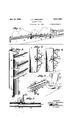
- Fig. 1 is a perspective view of a portion oiv a highway equipped with a guard embodying my invention.
- Fig. 2 is an enlarged detail perspective view of a portion of a guard rail of my improved construction attached to a supporting post in accordance with my invention.
- Fig. 3 is a vertical section of a portion of a guard rail and supporting posts illustrating relative depth of the central or guide trough corrugation of a rail section and initial application of a rail section to its supporting post.
- Fig. 4 is a view similar to Fig. 3 but showing the rail section permanently attached to a supporting post and illustrating normal spread of the side wings in response to tightening of the attaching bolt.
- Fig. 5 is a plan view, partly in horizontal secportions overlapped and attached to a supporting post by a common attaching bolt.
- Fig. 6 is a perspective'view of part of a rail guard attached at an intermediate 'point to a 'tion, of adjacent guard rail sections having end 15 supporting post and illustrating positioning of 20
- Fig. 11 is a view similar to Fig. 10 but illustrating the ends of the rail sections extended beyond and connected at opposite sides of a supporting post.
- Fig. 12 is a horizontal section illustrating a modified form of attachment of overlapped rail sections to a supporting post.
- I designates supporting posts, set in spaced relation along a highway for supporting guard rails 2 at a distance from the path of traflic indicated by the slab 3 to avoid interference with normal traflic, but sufliciently close to the slab to promptly interrupt accidental departure of a vehicle from the slab.
- the posts for supporting the guard rail may be of any suitable form or material afiording flat faces 4 of substantial area for bearing of the guard rail thereagainst, those shown in Figs. 1 to 5 inclusive being of heavy sheet or structural metal, Z-shaped to provide a central web 5, and
- the guard rail 2 is formed in sections, each composed of a strip of sheet metal corrugated longitudinally to provide a central trough 9, shoulders l0, H at opposite sides of the trough, and edge wings l2, l3 formed by outward curvature of the edges of the side walls I4, 85 of the reverse corrugations at the sides of the central trough.
- the intermediate corrugation constituting the trough 9 is shallower than those at its opposite sides, so that when the rail sections are initially positioned against the flat faces of the supporting posts, the trough portion will be spaced from the posts by contact of the edge wings with the posts.
- l6 designates apertures located in the base of the trough of each rail section and adapted to register with apertures H in the front flanges 6 of adjacent metal posts or with bolt holes H3 in adjacent wooden posts; and I9 designates bolts adapted for projection through the apertures l6 and I! or through the apertures l6 and bolt holes l8 for attaching the rail sections to the posts, the bolt heads 20 being preferably rounded to seat snugly in the base of the trough and the nuts 2!
- Such single point attachment of the rail sections to the supporting posts permits the spreading action described and affords automatic adjustment of the rail sections on the supporting posts that tends to avert shearing of the bolts or tearing of the rail sections in response to vertical stresses resulting from impact of a vehicle against the rail' at an upward or downward angle.
- the rail sections may be made of standard length and the supporting posts spaced accordingly so that each section may be attached to adjacent posts only at its ends, or also to intervening posts intermediate the ends of the sections.
- the rail sections are so set on the supporting posts that the central troughs 9 will receive the hub cap of an ordinary motor vehicle when impact of the vehicle is at a forward angle to the rail, and tend to retain the cap in the trough, thereby guiding the vehicle to a line of travel parallel with the highway and tending to hold the vehicle from overturning.
- the corrugations in the railsections will space the shoulders and the outer portions of the trough walls from the supporting posts to avoid impact of the vehicle wheels against the posts when the vehicle has been directed to travel along and in contact with the rail, but without sacrificing the security of direct attachment of the rail sections to the supporting posts.
- the overlap is made in direction of the flow of traflic in order to avoid abutment of any part of a ve hicle with the end of a rail section.
- Overlaps of the rail sections are preferably made at the post positions in order to permit attachment of two rail sections to a post with a single bolt and to provide backing of the post for the underlapped portions of a rail section adjacent that to which thrust has been imparted.
- connecting bolts 23 may be combined with those of the attaching bolts 49 by forming a thread 241 (Fig. 7) on the shank of the attaching bolt adjacent the head 20, so that nuts 25 may be employed to clamp overlapped ends of the rail sections together.
- the posts are provided with the sockets 8 to receive the nuts 25 and permit the lapped portions of the rail sections to lie flat along the posts.
- the overlapped portions of rail sections may merely be clamped to the posts by the heads of the attaching bolts l9, burrs 25 left on the metal sections from the bolt hole punching being drawn into the faces of the posts to provide anchorage.
- the guard will, because of its inherent longitudinal rigidity, provide a gradual guideway for the vehicle to and past the adjacent post position, the corrugations serving as spacers between the vehicle and post.
- a highway guard including spaced supports, a guard rail comprising a band corrugated longitudinally to form a relatively shallow trough and deep rail portions having contact faces at the same side of the rail in spaced parallel planes, the faces of the rail portions having sliding contact with the supports at opposite sides of the trough portion, and fastening means on the supports extending through the base of the trough portion adapted for drawing the contact face of the trough portion against the supports to attach the band to the supports and tension the rail portions in sliding contact with the supports.
- a highway guard including spaced supports, a band having spaced edge portions contacting said supports and an intermediate portion normally outset from the supports, and means securing the band to the supports and adapted for drawing said intermediate portion toward the supports.
- a highway guard including a support, a guardrail comprising a metal band corrugated longitudinally to form atrough between adjacent rail portions, means on the support adjustably carrying the band for movement toward the sup-v port, and means on the rail portions contacting the support for efiecting expansion of the rail in response to movement of the. band toward the support.
- a highway guard including a support, a guard rail comprising band sections corrugated longitudinally to form a trough andoutwardly facing rail portions at the sides of the trough having inwardly extending wing sections of greater depth than said trough, and means passing through the bottom of said trough and secured to the support for adjusting the trough relatively to said support whereby the wing sections areexpanded to impart initial tension to the rail portions.
- a highway guard including spaced supports, a guard rail formed of metallic band sections corrugated longitudinally to form a trough between outwardly facing rail portions and inwardly facing convex lips at opposite edges of the band sections extending inwardly beyond the trough, and means extending through the bottom of the trough for, attaching the band sections to the supports and permitting free sliding movement of the edge lips on the supports in response to thrust on the rail portions.
- a highway guard including spaced supports, a guard rail comprising band sections corrugated longitudinally to form a relatively shallow trough and deep rail portions having free sliding contact with the supports at the sides of the trough to normally space the trough from the support, and means on the supports for drawing the trough toward the support.
- a highway guard including a support, a guard rail comprising band sections corrugated sections.
- a highway guard including spaced posts, a guard rail comprising band sections having overlapping ends and corrugated longitudinally to 10 form a shallow trough and deep rail portions having free sliding contact with the posts, and means extending through the overlapping ends 01' the .band sections at the base 01' the trough to secure the band sections to the posts. 15
- a highway guard including in combination with spaced supports, corrugated band sections overlapped at their ends in nested relation, and means connecting corresponding outer walls of the overlapped sections to effect synchronous spreading of the sections transversely of the band sections in response to lateral thrust on said band sections.
- A, highway guard including in combination with spaced supports, corrugated band sections overlapped at their ends in nested relation, means connecting corresponding outer walls of the overlapped sections to effect synchronous spreading of the sections transversely of the band sections in response to lateral thrust on said band sections, and means extending, through a trough portion of said sections intermediate said walls providing single point attachment of the sections to each of said supports.
- a highway guard including in combination with spaced posts, metallic band sections each corrugated longitudinally to form relatively shal-' low central trough portions and deep side wing portions, end portions of adjacent sections being overlapped at a side of a post, means extending through corresponding side walls of the band I sections for connecting said sections, and means extending through the bottoms of overlapped trough portions of said sections'for providing single point attachment of said sections to the posts.
- a highway guard including in combination with spaced posts, metallic band sections each corrugated longitudinally to form relatively shallow central trough portions. and deep side wing portions, end portions of adjacent sections being overlapped at a side of a post, means extending through corresponding side walls and through the; bottoms of the trough portions of the -band-sec- 55 tions for connecting said sections, and means ex tending through the bottoms of overlapped trough portions of said sections for providing single point attachment of said sections to the posts.
- a highway guard including in combination with spaced posts, aligning metallic band sections having longitudinal corrugations to form relatively shallow central trough portions and deep side wing portions, end portions of adjacent band sections being overlapped adjacent one of 65 said posts, a bolt including a head, a shank extending through said post to adjustably secure the band sections to the post and having a threaded portion adjacent the head extending through said overlapping end portions of adjacent band sections, and a nut on the bolt for cooperating with said head to secure the band sections together.
Landscapes
- Engineering & Computer Science (AREA)
- Architecture (AREA)
- Civil Engineering (AREA)
- Structural Engineering (AREA)
- Refuge Islands, Traffic Blockers, Or Guard Fence (AREA)
Description
July 14, 1936. J. c. SHEPHERD HIGHWAY GUAR D 2 Sheets-Sheet l Filed Aug. 20, 1934 INVENTOR Jame C. .S/zep/vemf BYM ATTORNEY y 1936- J. c. SHEPHERD 2,047,436
HIGHWAY GUARD Filed Aug. 20, 1934 2 Sheets-Speet 2 ATTORNEY Patented July 14, 1936 HIGHWAY GUARD James (3. Shepherd, Kansas City, Mo., assignor to Sheffield Steel Corporation, Kansas City, Mo.,
a. corporation oi. Delaware Application August 20; 1934, Serial No. 740,569
13 Claims.
My invention relates to highway guards, and more particularly to a structure of that character adapted for erection at curves, along embankments, and at other points adjacent a highway where serious injury to occupants of a vehicle and damage to the vehicle might result from accidental departure of the vehicle from the highway proper.
. Guards of this character must have flexibility in some direction to absorb impact of a vehicle thereagainst, but if the guard is over-resilient an impacting vehicle may be thrown back onto the highway in the path of traflic, or overturned.
by reflex of the guard or, if impact of the vehicle is at a -suflicient angle to the guard, the vehicle will travel along the guard to damaging impact with an adjacent post. Avoidance of one of the mentioned difliculties has been sought by spacing guard rails from the supporting posts but with such constructions the spacing elements are liable to breakage by stress of the vehicle impact against the guard rail and themselves form obstructions, as do the posts proper.
It is the principal object of my invention to provide a highway guard including rail members of substantial longitudinal rigidity which, when attached directly to supporting posts, will have .suflicient yieldability through the attaching conmenting the cushioning efiect provided by the mechanical yielding before mentioned.
More particularly my invention contemplates employment of a guard rail formed of sections of corrugated metal arranged in longitudinal alignment and having single point connection with the supporting posts, toprovide a guideway for the hub caps of the impacting vehicles, and including side wings above and below the central guiding trough having slip contact with the supporting posts to permit the transverse flexibility of the rails by spreading of the free side wings thereof.
The foregoing and other features of improvement which I claim as my'invention are illustrated in the accompanying drawings, wherein:
Fig. 1 is a perspective view of a portion oiv a highway equipped with a guard embodying my invention.
Fig. 2 is an enlarged detail perspective view of a portion of a guard rail of my improved construction attached to a supporting post in accordance with my invention.
Fig. 3 is a vertical section of a portion of a guard rail and supporting posts illustrating relative depth of the central or guide trough corrugation of a rail section and initial application of a rail section to its supporting post.
Fig. 4 is a view similar to Fig. 3 but showing the rail section permanently attached to a supporting post and illustrating normal spread of the side wings in response to tightening of the attaching bolt.
Fig. 5 is a plan view, partly in horizontal secportions overlapped and attached to a supporting post by a common attaching bolt.
Fig. 6 is a perspective'view of part of a rail guard attached at an intermediate 'point to a 'tion, of adjacent guard rail sections having end 15 supporting post and illustrating positioning of 20 Fig. 11 is a view similar to Fig. 10 but illustrating the ends of the rail sections extended beyond and connected at opposite sides of a supporting post.
Fig. 12 is a horizontal section illustrating a modified form of attachment of overlapped rail sections to a supporting post.
Referring more in detail to the drawings:
I designates supporting posts, set in spaced relation along a highway for supporting guard rails 2 at a distance from the path of traflic indicated by the slab 3 to avoid interference with normal traflic, but sufliciently close to the slab to promptly interrupt accidental departure of a vehicle from the slab.
The posts for supporting the guard rail may be of any suitable form or material afiording flat faces 4 of substantial area for bearing of the guard rail thereagainst, those shown in Figs. 1 to 5 inclusive being of heavy sheet or structural metal, Z-shaped to provide a central web 5, and
parallel front and rear flanges 6, I so that the F posts may be set with the flanges parallel with the contemplated longitudinal plane of the guard rail to provide the bearing faces 4. The wooden posts illustrated in Figs. 7 to 12 inclusive, are
preferably .square in cross section and may be 60 provided in their front faces with sockets 8 for securing nuts on the rail attaching bolts as and for the purpose presently described.
The guard rail 2 is formed in sections, each composed of a strip of sheet metal corrugated longitudinally to provide a central trough 9, shoulders l0, H at opposite sides of the trough, and edge wings l2, l3 formed by outward curvature of the edges of the side walls I4, 85 of the reverse corrugations at the sides of the central trough. The intermediate corrugation constituting the trough 9 is shallower than those at its opposite sides, so that when the rail sections are initially positioned against the flat faces of the supporting posts, the trough portion will be spaced from the posts by contact of the edge wings with the posts.
l6 designates apertures located in the base of the trough of each rail section and adapted to register with apertures H in the front flanges 6 of adjacent metal posts or with bolt holes H3 in adjacent wooden posts; and I9 designates bolts adapted for projection through the apertures l6 and I! or through the apertures l6 and bolt holes l8 for attaching the rail sections to the posts, the bolt heads 20 being preferably rounded to seat snugly in the base of the trough and the nuts 2! adapted to press washers 22 against the opposite faces of the posts or post flanges to draw the wings of the rail sections firmly against the outer, fiat faces of the posts or post flanges; continued tightening of the bolts drawing the central trough portions of the rail sections toward the posts,
and spreading the side shoulders to impart initial tension to the rail sections. Such single point attachment of the rail sections to the supporting posts permits the spreading action described and affords automatic adjustment of the rail sections on the supporting posts that tends to avert shearing of the bolts or tearing of the rail sections in response to vertical stresses resulting from impact of a vehicle against the rail' at an upward or downward angle.
The rail sections may be made of standard length and the supporting posts spaced accordingly so that each section may be attached to adjacent posts only at its ends, or also to intervening posts intermediate the ends of the sections.
I prefer, however, to overlap ends of adjacent rail sections at the post positions and to extend the attaching bolts through the overlapped ends of the sections, as in that way load applied to any portion of the rail by impact of a vehicle at that point may be relayed from section to section throughout the length of the rail and the thrust gradually absorbed by longitudinal shift of the sections along the successive posts due to some looseness of the attaching bolts in their apertures in the rail sections and posts, and to give of the post settings in the ground, thereby providing the equivalent of a flexing of the rail to cushion the impact of the vehicle, but avoiding the undesirable rebound that would follow impact of the vehicle against a resilient rail.
The rail sections are so set on the supporting posts that the central troughs 9 will receive the hub cap of an ordinary motor vehicle when impact of the vehicle is at a forward angle to the rail, and tend to retain the cap in the trough, thereby guiding the vehicle to a line of travel parallel with the highway and tending to hold the vehicle from overturning. The corrugations in the railsections will space the shoulders and the outer portions of the trough walls from the supporting posts to avoid impact of the vehicle wheels against the posts when the vehicle has been directed to travel along and in contact with the rail, but without sacrificing the security of direct attachment of the rail sections to the supporting posts.
When the rail sections are overlapped, the overlap is made in direction of the flow of traflic in order to avoid abutment of any part of a ve hicle with the end of a rail section. Overlaps of the rail sections are preferably made at the post positions in order to permit attachment of two rail sections to a post with a single bolt and to provide backing of the post for the underlapped portions of a rail section adjacent that to which thrust has been imparted.
Regardless of where the overlap occurs, I prefer to connect the overlapped ends of adjacentrail sections by bolts 23 that are extended through the bottom of the trough portions 9 and through the side walls I l, I5 of the outer corrugations in order further to avoid any abutment in the path of travel of a vehicle along the rail. It is preferable to extend overlap of the sections at both sides of a post and provide a series of connecting bolts 23 at each end of the overlap, as in this Way any tendency of one rail sectionto rock on the other is obviated by the series of bolts at the opposite sides of the post.
Function of the connecting bolts 23 may be combined with those of the attaching bolts 49 by forming a thread 241 (Fig. 7) on the shank of the attaching bolt adjacent the head 20, so that nuts 25 may be employed to clamp overlapped ends of the rail sections together. When this form of connection is employed, the posts are provided with the sockets 8 to receive the nuts 25 and permit the lapped portions of the rail sections to lie flat along the posts.
In a further modified form of the invention (Fig. 12) the overlapped portions of rail sections may merely be clamped to the posts by the heads of the attaching bolts l9, burrs 25 left on the metal sections from the bolt hole punching being drawn into the faces of the posts to provide anchorage.
Assuming a guard rail constructed and mounted as described to be struck by a motor vehicle out of control, the impact, except in most unusual cases, would be with the vehicle traveling at at least a slight forward angle so that there would be a tendency to deflect the vehicle to a line of travel parallel with the rail. If the impact is from some part of the body, bumper or fender of the vehicle against the rail, such part of the vehicle would contact one or both of the shoulders of the rail at the sides of the central trough,
and the major effect of the blow would be to force the rail inwardly, thereby effecting a pull on both ends of the contacted rail section that would be immediately relayed to adjacent rail sections and supporting posts and on through the series of sections and supporting posts; each section yielding some slack and each post setting yielding according to 'the pull on it so that the load of the impact would be gradually absorbed by the entire guard instead of by the individual rail section and its immediately adjacent supporting posts, lag in absorption of the impact providing resistance to the thrust and yielding of the immediate and successive sections cushioning of the thrust, without the disadvantage of a too rigid reaistanae on the one hand or a rebound resiliency on the other hand. Some additional cushioning eil'ect would also be imparted by transverse spread 01' the unanchored side corrugations of the rail.
It the vehicle be under sufilcient headway to continue travel after deflection by the guard, the guard will, because of its inherent longitudinal rigidity, provide a gradual guideway for the vehicle to and past the adjacent post position, the corrugations serving as spacers between the vehicle and post.
What I claim and desire to secure by Letters Patent is:
l. A highway guard including spaced supports, a guard rail comprising a band corrugated longitudinally to form a relatively shallow trough and deep rail portions having contact faces at the same side of the rail in spaced parallel planes, the faces of the rail portions having sliding contact with the supports at opposite sides of the trough portion, and fastening means on the supports extending through the base of the trough portion adapted for drawing the contact face of the trough portion against the supports to attach the band to the supports and tension the rail portions in sliding contact with the supports.
2. A highway guard including spaced supports, a band having spaced edge portions contacting said supports and an intermediate portion normally outset from the supports, and means securing the band to the supports and adapted for drawing said intermediate portion toward the supports.
3. A highway guard including a support, a guardrail comprising a metal band corrugated longitudinally to form atrough between adjacent rail portions, means on the support adjustably carrying the band for movement toward the sup-v port, and means on the rail portions contacting the support for efiecting expansion of the rail in response to movement of the. band toward the support.
4. A highway guard including a support, a guard rail comprising band sections corrugated longitudinally to form a trough andoutwardly facing rail portions at the sides of the trough having inwardly extending wing sections of greater depth than said trough, and means passing through the bottom of said trough and secured to the support for adjusting the trough relatively to said support whereby the wing sections areexpanded to impart initial tension to the rail portions.
5. A highway guard including spaced supports, a guard rail formed of metallic band sections corrugated longitudinally to form a trough between outwardly facing rail portions and inwardly facing convex lips at opposite edges of the band sections extending inwardly beyond the trough, and means extending through the bottom of the trough for, attaching the band sections to the supports and permitting free sliding movement of the edge lips on the supports in response to thrust on the rail portions.
6. A highway guard including spaced supports, a guard rail comprising band sections corrugated longitudinally to form a relatively shallow trough and deep rail portions having free sliding contact with the supports at the sides of the trough to normally space the trough from the support, and means on the supports for drawing the trough toward the support.
7. A highway guard including a support, a guard rail comprising band sections corrugated sections.
8. A highway guard including spaced posts, a guard rail comprising band sections having overlapping ends and corrugated longitudinally to 10 form a shallow trough and deep rail portions having free sliding contact with the posts, and means extending through the overlapping ends 01' the .band sections at the base 01' the trough to secure the band sections to the posts. 15
9. A highway guard including in combination with spaced supports, corrugated band sections overlapped at their ends in nested relation, and means connecting corresponding outer walls of the overlapped sections to effect synchronous spreading of the sections transversely of the band sections in response to lateral thrust on said band sections.
10. A, highway guard including in combination with spaced supports, corrugated band sections overlapped at their ends in nested relation, means connecting corresponding outer walls of the overlapped sections to effect synchronous spreading of the sections transversely of the band sections in response to lateral thrust on said band sections, and means extending, through a trough portion of said sections intermediate said walls providing single point attachment of the sections to each of said supports.
11. A highway guard including in combination with spaced posts, metallic band sections each corrugated longitudinally to form relatively shal-' low central trough portions and deep side wing portions, end portions of adjacent sections being overlapped at a side of a post, means extending through corresponding side walls of the band I sections for connecting said sections, and means extending through the bottoms of overlapped trough portions of said sections'for providing single point attachment of said sections to the posts.
12. A highway guard including in combination with spaced posts, metallic band sections each corrugated longitudinally to form relatively shallow central trough portions. and deep side wing portions, end portions of adjacent sections being overlapped at a side of a post, means extending through corresponding side walls and through the; bottoms of the trough portions of the -band-sec- 55 tions for connecting said sections, and means ex tending through the bottoms of overlapped trough portions of said sections for providing single point attachment of said sections to the posts.
13. A highway guard including in combination with spaced posts, aligning metallic band sections having longitudinal corrugations to form relatively shallow central trough portions and deep side wing portions, end portions of adjacent band sections being overlapped adjacent one of 65 said posts, a bolt including a head, a shank extending through said post to adjustably secure the band sections to the post and having a threaded portion adjacent the head extending through said overlapping end portions of adjacent band sections, and a nut on the bolt for cooperating with said head to secure the band sections together.
James 0. s.
Priority Applications (1)
| Application Number | Priority Date | Filing Date | Title |
|---|---|---|---|
| US740569A US2047436A (en) | 1934-08-20 | 1934-08-20 | Highway guard |
Applications Claiming Priority (1)
| Application Number | Priority Date | Filing Date | Title |
|---|---|---|---|
| US740569A US2047436A (en) | 1934-08-20 | 1934-08-20 | Highway guard |
Publications (1)
| Publication Number | Publication Date |
|---|---|
| US2047436A true US2047436A (en) | 1936-07-14 |
Family
ID=24977097
Family Applications (1)
| Application Number | Title | Priority Date | Filing Date |
|---|---|---|---|
| US740569A Expired - Lifetime US2047436A (en) | 1934-08-20 | 1934-08-20 | Highway guard |
Country Status (1)
| Country | Link |
|---|---|
| US (1) | US2047436A (en) |
Cited By (25)
| Publication number | Priority date | Publication date | Assignee | Title |
|---|---|---|---|---|
| US2942853A (en) * | 1957-12-26 | 1960-06-28 | Glaros Emanuel Michael | Highway guard rail structures |
| US2979307A (en) * | 1958-02-10 | 1961-04-11 | Acme Highway Prod | Highway guard rail and post therefor |
| US3140885A (en) * | 1961-07-07 | 1964-07-14 | Kaiser Aluminium Chem Corp | Lap joint for highway guard rail |
| US4191449A (en) * | 1977-02-28 | 1980-03-04 | Toyo Seikan Co., Ltd. | Guard-rail reflector |
| US4460161A (en) * | 1983-03-02 | 1984-07-17 | Grenga Joseph R | Guard rail and reflective strip |
| FR2589176A1 (en) * | 1985-10-28 | 1987-04-30 | Gaillard Rondino Cie Fse Ets | Device for constructing and assembling timber crash barriers |
| FR2641804A1 (en) * | 1989-01-17 | 1990-07-20 | Pomero Claude | ROAD SAFETY SLIDER WITH WINGS DEVELOPED |
| US5022782A (en) * | 1989-11-20 | 1991-06-11 | Energy Absorption Systems, Inc. | Vehicle crash barrier |
| US5385423A (en) * | 1990-04-09 | 1995-01-31 | Toko Tekko Kabushiki Kaisha | Joint for corrugated structural members |
| US5967497A (en) * | 1997-12-15 | 1999-10-19 | Energy Absorption Systems, Inc. | Highway barrier and guardrail |
| WO2000049232A1 (en) * | 1999-02-16 | 2000-08-24 | Trn Business Trust | Guardrail beam with enhanced stability |
| US6220576B1 (en) * | 1998-12-25 | 2001-04-24 | Raymond Chi Lap Chan | Flexible road safety-guard |
| US6260827B1 (en) * | 1996-01-05 | 2001-07-17 | The Board Of Regents Of The University Of Nebraska | Guardrail system |
| US6533249B2 (en) | 1999-09-23 | 2003-03-18 | Icom Engineering, Inc. | Guardrail beam with improved edge region and method of manufacture |
| US6554256B2 (en) | 2001-04-25 | 2003-04-29 | Icom Engineering, Inc. | Highway guardrail end terminal assembly |
| US6644888B2 (en) * | 2001-11-06 | 2003-11-11 | Carlos M. Ochoa | Roadway guardrail structure |
| US20050036832A1 (en) * | 2003-08-12 | 2005-02-17 | Smith Jeffery D. | Crash attenuator with cable and cylinder arrangement for decelerating vehicles |
| US20060082881A1 (en) * | 2004-05-11 | 2006-04-20 | Garcia Guadalupe C | Guardrail reflector/delineator and mounting device therefor |
| US20070063179A1 (en) * | 2005-09-19 | 2007-03-22 | Alberson Dean C | A weakened guardrail mounting connection |
| US20070215849A1 (en) * | 2006-03-01 | 2007-09-20 | Alberson Dean C | Yielding post guardrail safety system incorporating thrie beam guardrail elements |
| US20070228350A1 (en) * | 2006-02-07 | 2007-10-04 | Joseph Szuba | Guardrail assembly and method of installing the guardrail assembly |
| US20080083914A1 (en) * | 2004-07-19 | 2008-04-10 | Ochoa Carlos M | Posts and release mechanism for highway safety structures |
| US7530548B2 (en) | 2004-07-19 | 2009-05-12 | Ochoa Carlos M | Releasable highway safety structures |
| EP3825464A1 (en) * | 2019-11-21 | 2021-05-26 | voestalpine Krems Finaltechnik GmbH | Vehicle restraint system |
| US11891765B2 (en) | 2022-05-19 | 2024-02-06 | Vandorf BT1 Inc. | Barrier transition framework |
-
1934
- 1934-08-20 US US740569A patent/US2047436A/en not_active Expired - Lifetime
Cited By (43)
| Publication number | Priority date | Publication date | Assignee | Title |
|---|---|---|---|---|
| US2942853A (en) * | 1957-12-26 | 1960-06-28 | Glaros Emanuel Michael | Highway guard rail structures |
| US2979307A (en) * | 1958-02-10 | 1961-04-11 | Acme Highway Prod | Highway guard rail and post therefor |
| US3140885A (en) * | 1961-07-07 | 1964-07-14 | Kaiser Aluminium Chem Corp | Lap joint for highway guard rail |
| US4191449A (en) * | 1977-02-28 | 1980-03-04 | Toyo Seikan Co., Ltd. | Guard-rail reflector |
| US4460161A (en) * | 1983-03-02 | 1984-07-17 | Grenga Joseph R | Guard rail and reflective strip |
| FR2589176A1 (en) * | 1985-10-28 | 1987-04-30 | Gaillard Rondino Cie Fse Ets | Device for constructing and assembling timber crash barriers |
| EP0379424A3 (en) * | 1989-01-17 | 1991-03-20 | Les Profiles Du Centre - L.P.C., S.A. | Road safety barrier |
| EP0379424A2 (en) * | 1989-01-17 | 1990-07-25 | Les Profiles Du Centre - L.P.C., S.A. | Road safety barrier |
| US5069576A (en) * | 1989-01-17 | 1991-12-03 | Les Profiles Du Centre | Road safety barrier |
| FR2641804A1 (en) * | 1989-01-17 | 1990-07-20 | Pomero Claude | ROAD SAFETY SLIDER WITH WINGS DEVELOPED |
| US5022782A (en) * | 1989-11-20 | 1991-06-11 | Energy Absorption Systems, Inc. | Vehicle crash barrier |
| US5385423A (en) * | 1990-04-09 | 1995-01-31 | Toko Tekko Kabushiki Kaisha | Joint for corrugated structural members |
| US6260827B1 (en) * | 1996-01-05 | 2001-07-17 | The Board Of Regents Of The University Of Nebraska | Guardrail system |
| US5967497A (en) * | 1997-12-15 | 1999-10-19 | Energy Absorption Systems, Inc. | Highway barrier and guardrail |
| US6142452A (en) * | 1997-12-15 | 2000-11-07 | Energy Absorption Systems, Inc. | Highway barrier and guardrail |
| US6220576B1 (en) * | 1998-12-25 | 2001-04-24 | Raymond Chi Lap Chan | Flexible road safety-guard |
| US6558067B2 (en) | 1999-02-16 | 2003-05-06 | Icom Engineering, Inc. | Guardrail beam with enhanced stability |
| US6290427B1 (en) | 1999-02-16 | 2001-09-18 | Carlos M. Ochoa | Guardrail beam with enhanced stability |
| WO2000049232A1 (en) * | 1999-02-16 | 2000-08-24 | Trn Business Trust | Guardrail beam with enhanced stability |
| US6830407B1 (en) | 1999-02-16 | 2004-12-14 | Icom Engineering, Inc. | Guardrail beam with enhanced stability |
| US6533249B2 (en) | 1999-09-23 | 2003-03-18 | Icom Engineering, Inc. | Guardrail beam with improved edge region and method of manufacture |
| US6554256B2 (en) | 2001-04-25 | 2003-04-29 | Icom Engineering, Inc. | Highway guardrail end terminal assembly |
| US6644888B2 (en) * | 2001-11-06 | 2003-11-11 | Carlos M. Ochoa | Roadway guardrail structure |
| US20050036832A1 (en) * | 2003-08-12 | 2005-02-17 | Smith Jeffery D. | Crash attenuator with cable and cylinder arrangement for decelerating vehicles |
| US20050047862A1 (en) * | 2003-08-12 | 2005-03-03 | Sci Products Inc. | Side panel |
| US20050063777A1 (en) * | 2003-08-12 | 2005-03-24 | Sci Products Inc. | Apparatus for exerting a resisting force |
| US20050244224A1 (en) * | 2003-08-12 | 2005-11-03 | Sci Products Inc. | Crash attenuator with cable and cylinder arrangement for decelerating vehicles |
| US6962459B2 (en) | 2003-08-12 | 2005-11-08 | Sci Products Inc. | Crash attenuator with cable and cylinder arrangement for decelerating vehicles |
| US7018130B2 (en) | 2003-08-12 | 2006-03-28 | Sci Products Inc. | Side panel |
| US7086805B2 (en) | 2003-08-12 | 2006-08-08 | Sci Products Inc. | Crash attenuator with cable and cylinder arrangement for decelerating vehicles |
| US7070031B2 (en) | 2003-08-12 | 2006-07-04 | Sci Products Inc. | Apparatus for exerting a resisting force |
| US20060082881A1 (en) * | 2004-05-11 | 2006-04-20 | Garcia Guadalupe C | Guardrail reflector/delineator and mounting device therefor |
| US7300165B2 (en) * | 2004-05-11 | 2007-11-27 | Worldwide Safety, Inc. | Guardrail reflector/delineator and mounting device therefor |
| US20080083914A1 (en) * | 2004-07-19 | 2008-04-10 | Ochoa Carlos M | Posts and release mechanism for highway safety structures |
| US7530548B2 (en) | 2004-07-19 | 2009-05-12 | Ochoa Carlos M | Releasable highway safety structures |
| US20090194752A1 (en) * | 2004-07-19 | 2009-08-06 | Ochoa Carl M | Releasable Highway Safety Structures |
| US7878486B2 (en) | 2004-07-19 | 2011-02-01 | Carl M. Ochoa | Releasable highway safety structures |
| US20070063179A1 (en) * | 2005-09-19 | 2007-03-22 | Alberson Dean C | A weakened guardrail mounting connection |
| US20070228350A1 (en) * | 2006-02-07 | 2007-10-04 | Joseph Szuba | Guardrail assembly and method of installing the guardrail assembly |
| US20070215849A1 (en) * | 2006-03-01 | 2007-09-20 | Alberson Dean C | Yielding post guardrail safety system incorporating thrie beam guardrail elements |
| US8500103B2 (en) | 2006-03-01 | 2013-08-06 | The Texas A&M University System | Yielding post guardrail safety system incorporating thrie beam guardrail elements |
| EP3825464A1 (en) * | 2019-11-21 | 2021-05-26 | voestalpine Krems Finaltechnik GmbH | Vehicle restraint system |
| US11891765B2 (en) | 2022-05-19 | 2024-02-06 | Vandorf BT1 Inc. | Barrier transition framework |
Similar Documents
| Publication | Publication Date | Title |
|---|---|---|
| US2047436A (en) | Highway guard | |
| KR101339447B1 (en) | Guardrail end terminal | |
| US9725857B2 (en) | Crash cushion | |
| JPH11343614A (en) | Guard rail equipped with slidable impact force receiving element | |
| US3658300A (en) | Vehicle guard for highways | |
| US1989763A (en) | Highway guard | |
| US2979307A (en) | Highway guard rail and post therefor | |
| CS198371B1 (en) | Railing | |
| KR101083269B1 (en) | Vehicle protective fence | |
| US2093577A (en) | Highway guard | |
| US2988332A (en) | Guard rail for roads | |
| US2056842A (en) | Highway guard | |
| US1922878A (en) | Road guard mounting | |
| US2160519A (en) | Road guard fence | |
| US1793675A (en) | Road guard | |
| US2106601A (en) | Fence | |
| KR101192586B1 (en) | Guardrails for Absorption of Impact | |
| US2213239A (en) | Highway guardrail | |
| US1867671A (en) | Safety zone guard | |
| KR101190671B1 (en) | Guardrail | |
| US1855506A (en) | Road guard | |
| US2164084A (en) | Road guard fence | |
| KR101703944B1 (en) | installation structure of glare shield for median strip | |
| KR101259931B1 (en) | Guard rail end shock absorber | |
| US2296432A (en) | Highway guard |