US2041350A - Mechanical puddler - Google Patents
Mechanical puddler Download PDFInfo
- Publication number
- US2041350A US2041350A US524393A US52439331A US2041350A US 2041350 A US2041350 A US 2041350A US 524393 A US524393 A US 524393A US 52439331 A US52439331 A US 52439331A US 2041350 A US2041350 A US 2041350A
- Authority
- US
- United States
- Prior art keywords
- shaft
- machine
- road
- shafts
- distributor
- Prior art date
- Legal status (The legal status is an assumption and is not a legal conclusion. Google has not performed a legal analysis and makes no representation as to the accuracy of the status listed.)
- Expired - Lifetime
Links
Images

Classifications
-
- E—FIXED CONSTRUCTIONS
- E01—CONSTRUCTION OF ROADS, RAILWAYS, OR BRIDGES
- E01C—CONSTRUCTION OF, OR SURFACES FOR, ROADS, SPORTS GROUNDS, OR THE LIKE; MACHINES OR AUXILIARY TOOLS FOR CONSTRUCTION OR REPAIR
- E01C19/00—Machines, tools or auxiliary devices for preparing or distributing paving materials, for working the placed materials, or for forming, consolidating, or finishing the paving
- E01C19/12—Machines, tools or auxiliary devices for preparing or distributing paving materials, for working the placed materials, or for forming, consolidating, or finishing the paving for distributing granular or liquid materials
- E01C19/18—Devices for distributing road-metals mixed with binders, e.g. cement, bitumen, without consolidating or ironing effect
- E01C19/185—Devices for distributing road-metals mixed with binders, e.g. cement, bitumen, without consolidating or ironing effect for both depositing and spreading-out or striking-off the deposited mixture
Definitions
- the present machine is also characterized by the fact that the spreading of the road material is accomplished by the use of a pair of screw conveyors the respective pitches of the vanes of which are opposite, one conveyor transporting the road material from the center of the roadway towards the lateral road forms while the other conveyor acts to bring the material to a common center, so that by operating the machine backwards and forwards on the road form rails a batch of aggregates deposited between the conveyors will be very quickly and uniformly distributed, by permitting dual transverse displacement of the material; and by providing instrumentalities for adjusting the amount of clearance of the conveyors the machine is made applicable to different stages of road building, as for the distribution of both the material for the base and for the top layer.
- a further object of this invention is to provide instrumentalities permitting the operator of the machine to raise and lower the above-mentioned screw conveyors either individually or both together which assists the distribution of the road material should it be, for any reason, deposited at the side of the road or near the road forms; in such circumstances the distribution of the deposited material will be accomplished by either raising the outwardly distributing conveyor out of contact with the batch and driving the inwardly distributing conveyor into the batch, or else by keeping the conveyors at the same level and maintaining the outwardly distributing conveyor out of contact with the batch. A most eflicient final distributing action will be had by keeping the conveyors at the same level and moving the machine back and forth over the roadway.
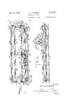
- FIG. 1 is a plan view of the machine.
- Fig. 2 is a front elevation thereof, certain parts being omitted.
- Fig. 3 is a side View. 10
- Fig. 4 is a horizontal section through the drive mechanism showing a portion thereof.
- Fig. 5 is a detail view showing instrumentalities for raising and lowering the. distributing conveyors and 15 Fig. 6 is a sectional view taken on the line 6-6 of Fig. 5.
- the machine comprises the frame A, housing B which contains the driving mechanisms, and the 20 distributing conveyors C and D which are slidably carried on the frame A, and which are rotated from a'source of power in the housing B, which source of power also operates the various other driven instrumentalities which comprise the uni- 25 tary machine.
- This source of power is indicated at I0 and is conveniently an internal combustion engine having a drive shaft II carrying with it the rotating sleeve I2, the shaft II being provided with a 30 sprocket wheel I 3 and the sleeve I2 being providedz with a sprocket wheel I4.
- this shaft is rotated, the motion of the shaft I'i being transmitted to the shaft I8 through 35 engagement of suitable clutch instrumentalities indicated at I9 (see Fig. 4).
- This clutch I9 is operated by the clutch lever 20, which in turn is operated by the rod 2l actuated by the lever 22 which is controlled by an operator of the 40 machine.
- the shaft I8 carries a sprocket wheel 23 over which passes a chain, or other suitable driving means, 24, which engages a sprocket 25 on the distributor shaft C to drive this shaft.
- Conveying distributor shaft C (see Fig. 1) is provided with a second sprocket 26 which engages a driving chain, or other suitable driving means, 2l, which passes over a sprocket 28, similar to sprocket 26, carried by the conveying distributor 50 shaft D by which motion is transmitted from shaft C to shaft D.
- the conveying distributors are provided with the spirally arranged vanes 29 on shaft C and 30 on shaft D; and it will be observed that the vanes 29 and 30 are pitched in opposite directions to assure distribution of the paving material in opposite directions, either from the center of the road-bed towards the sides thereof, or from the sides towards a common center.
- Vthe hollow shaft 30' surrounding the shaft I1 is Vthe hollow shaft 30', carrying the sprocket wheel 3
- the hollow shaft 30' is rotatable independently of the shaft I1, and carries a clutch member 33 actuated by the clutch lever 34 and rod 35 operated by a hand lever 36 under control of the operator of the machine.
- the clutch member 33 is the usual type of friction clutch and when the parts thereof are engaged, motion is transmitted to the sprocket wheel 31 and chain 38, which drives a sprocket wheel 39 for rotating the shaft 40.
- This shaft 49 has at each end a bevelled gear 4I and 4Ia (see Fig. l) co-acting respectively with the bevelled gears 42 and 42a on the shafts 43 and 43a, respectively, which shafts transmit the power required for raising and lowering the conveying distributor D.
- the shafts 43 and 43a are duplicates of each other, and since duplicate raising and lowering means are provided for each end of the distributor D, only one of these elements need be described in detail.
- one end of shaft 43 is provided with a bevelled gear 42 which is in engagement with the gear 4I.
- the other end of shaft 43 is provided with a similar bevelled gear 44 which engages a vertically disposed bevelled gear 45 (see Fig. 5 for details of construction) on the end of the threaded shaft 4B.
- the end of the shaft D' of the distributor D is journalled in a block 41 which is shaped as indicated in Fig. 6 to slide in the guide 48 as the shaft 46 is rotated.
- the guide 48 is mounted on the frame A of the machine.
- the transmission 49 (Fig.
- the transmission 49 is operated by the lever 5S under the control of the operator of the machine.
- the hollow shaft 30' (Fig. 4) is provided with still another clutch 53 operated by the clutch lever 54 and rod 55, which is operated by a lever 53.
- Engagement of the clutch elements of clutch 53 drives the sprocket wheel 51 which carries the chain 58 which engages the sprocket Vwheel 59 on the shaft 6U.
- Shaft 60 is similar to shaft 49, previously described, and serves a similar purpose; it is positioned, as shown, rearwardly of the shaft 49, and is supported together with shaft 49 in the supporting members 5! and 6Ia carried by the frame of the machine.
- the shafts 69 and 40 are journalled through the members 6
- the shaft 60 is provided at its respective ends with the bevelled gears 62 and 62a which engage the corresponding bevelled gears B3 and 63a on the shafts 64 and 64d. These shafts terminate in gears 65 and 85a, respectively, which operate the gears 66 and 66a on threaded shafts, exactly as above described; and through the provision of similar journal blocks for receiving the ends of the shaft C' of the distributor C, which blocks slide in guide members entirely similar to that shown at 48, the distributor C is raised or lowered as desired; and it will be seen that the distributors C and D are adjustable independently of each other.
- the machine be made self-propelling.
- flanged wheels mounted in pairs 61 and 61a on shafts 69 and 68a, respectively.
- Shafts B8 and 68a are provided with sprockets 69 and 69a with which the chain 10 engages, whereby motion is transmitted from the shaft 58 to shaft 68a to facilitate propulsion of the vehicle, the shaft 68 being driven from the engine I0 in the following manner:
- the clutch 1I Positioned upon the hollow shaft 39 is the clutch 1I operated by the clutch lever 12, rod 13 and lever 14. Operation of the clutch 1I to engage its members transfers motion to a sprocket 15 carrying the chain 16 to drive the sprocket 11 and shaft 18, which is journalled in suitable bearings as shown in Fig. 4.
- the shaft 18 carries the sprocket 19 which drives the chain 89 which engages a sprocket at 8
- Power is transmitted from the shaft B8 to the shaft 68a through the chain drive 10, as previously described to facilitate propulsion of the pair of wheels 91a mounted on the shaft 68a.
- the wheels 61 and 81a are shown as running on the road forms 82 and 82a which are placed upon the prepared subgrade 83.
- the conveyor vanes 29 and 39 are terminated short of the ends of their respective shafts C and D', since these vanes dip below the level of the tops of the side forms.
- adjustable strike off blades or screeds 85 and 85a are also carried by the frame, the adjustable strike off blades or screeds 85 and 85a, the height of which may be adjusted by suitable positioning of bolts 86 and 86a.
- These screeds are desirably positioned at both the front and rear ends of the machines, and assist in the forward movement of the material being distributed, reliance being placed upon the distributing conveyors for transverse distribution. Should the subgrade be covered with a number of batches of concrete from transit mixers, or other materials, the construction will permit the operator to drive the machine over the various batches after raising the distributing conveyors, the screeds then causing the preliminary longitudinal spreading action, either screed being used as desired.
- any suitable means for adjusting the position of the screeds can be employed in place of the bolts, as desired; and as a matter of fact, if desired, the screeds may be raised and lowered by the provision of mechanism like that previously described for raising and lowering the conveyors. For simplicity, however, the adjustment of the screeds as indicated by the bolts is shown on the drawings.
- a platform upon the framework A a fragment of which platform is indicated at 8l.
- a machine of the character described comprising the combination with a frame, of distributors adapted to convey road materials deposited on a roadway towards and away from a common center, vertical guide members secured to the frame and oppositely disposed on opposing ends of the frame, a block slidingly mounted in each guide, each distributor including a shaft having its ends journalled in opposing blocks, means to raise and lower the blocks in the guides for vertical adjustment of the shaft, a source of power, and means for transmitting motion from the source of power to the adjusting means for predeterminedly positioning the vertical adjustment of the shaft, and instrumentalities carried by the shafts for operating upon a surface for suitable conditioning thereof.
- a machine of the character described comprising the combination with a frame, of distributors adapted to convey road materials deposited on a roadway towards and away from a common center, oppositely disposed vertical guide members on the frame, a block slidingly mounted in each guide, the distributors including shafts having the ends thereof journalled in each pair of opposing blocks, means for selectively raising and lowering the blocks in the guides for selective vertical adjustment of the shafts for positioning either shaft into inoperative and operative positions, a source of power on the frame, driving means from the source of power for revolving the shafts, means independent of the driving means but operated from the source of power for predeterminedly positioning the vertical adjustment of the shafts, the said means comprising independently operable instrumentalities for adjusting either shaft and means for selectively operating the said instrumentalities whereby either shaft may be adjusted independently of the other.
- a machine of the character described comprising the combination with a frame, of a pair of oppositely acting distributors for distributing road materials on a road bed, a source of power, means actuated by the source of power for selectively moving the distributors in a vertical direction, driving mechanism for the distributors, traction devices for the machine adapted to run on usual road forms as tracks, the said traction devices being adjustably mounted to accommodate varying widths of roadway, the said means for selectively moving the distributors comprising cooperating driving shafts actuated by the said source of power, vertically acting shafts driven by the said cooperating shafts, a carrying member provided at each end of the distributors operated by the said vertically actuated shafts, and guides for the said carrying members for guiding the same for vertical movement of the distributors, each of the distributors comprising a shaft and distributing vanes on the shaft but terminating short from the ends thereof for allowing for adjustment of the said traction devices.
- a machine of the character described comprising the combination with a mobile frame, of a pair of oppositely acting distributors for distributing road building materials deposited on a road bed incident to movement of the machine over the deposited materials, each of said distributors including a shaft rotatably mounted in the frame and extending transversely of the road bed, with distributing vanes spirally disposed about said shaft, the vanes of one distributor being pitched to move the said road materials in a direction from the opposite edges of the road bed inwardly toward the center thereof, and the vanes of the other distributor being pitched to move the said road materials in a direction from the center of the road bed outwardly toward the edges thereof, and instrumentalities for rotating said distributor shafts.
- a machine of the character described comprising the combination with a mobile frame, of. a pair of oppositely acting distributors for distributing road building materials deposited on a road bed incident to movement of the machine over the deposited materials, each of said distributors including a shaft rotatably mounted in the frame and extending transversely of the road bed, with distributing vanes spirally disposed about said shaft, the vanes of one distributor being pitched to move the said road materials in a direction from the opposite edges of the road bed inwardly toward the center thereof, and the vanes of the other distributor being pitched to move the said road materials in a direction from the center of the road bed outwardly toward the edges thereof, instrumentalities for rotating said distributor shafts, and instrumentalities for selectively and independently elevating and lowering said distributors.
Landscapes
- Engineering & Computer Science (AREA)
- Architecture (AREA)
- Civil Engineering (AREA)
- Structural Engineering (AREA)
- Road Paving Machines (AREA)
Description
MW 399.3936 M. o JOHNSON MECHANICAL lPUDDLER Filed March 2l, 1931 I 2 Sheets-Sheet l www K me/wko@ MHRw/v 0. Jam/5W.
@Y W, .W35 M. o JoHNsoN MECHANICAL PUDDLER i Filed March 21, 1931 2 Sheets-Sheet 2 duur/wege Patented May 19, 1936 UNITED STATES PATENT OFFICE ME CHANIC'AL PUDDLER ration Application March 21, 1931, Serial No. 524,393
5 Claims.
In the laying of roads, pavements, and the like, it is obviously necessary that the road material, such as concrete, be uniformly and evenly distributed over the roadbed, this even distribution being required both for the concrete employed on the sub-grade, and for the top layer of concrete which is laid over the steel reinforcing members disposed in the concrete base.
For the assurance of such even distribution with a minimum of labor and trouble, it is proposed, in accordance with tlns invention, to provide a power driven machine which is propelled by a source of power over a sub-grade or surface being worked upon, the usual road forms acting as rails along which the machine travels.
The present machine is also characterized by the fact that the spreading of the road material is accomplished by the use of a pair of screw conveyors the respective pitches of the vanes of which are opposite, one conveyor transporting the road material from the center of the roadway towards the lateral road forms while the other conveyor acts to bring the material to a common center, so that by operating the machine backwards and forwards on the road form rails a batch of aggregates deposited between the conveyors will be very quickly and uniformly distributed, by permitting dual transverse displacement of the material; and by providing instrumentalities for adjusting the amount of clearance of the conveyors the machine is made applicable to different stages of road building, as for the distribution of both the material for the base and for the top layer.
A further object of this invention is to provide instrumentalities permitting the operator of the machine to raise and lower the above-mentioned screw conveyors either individually or both together which assists the distribution of the road material should it be, for any reason, deposited at the side of the road or near the road forms; in such circumstances the distribution of the deposited material will be accomplished by either raising the outwardly distributing conveyor out of contact with the batch and driving the inwardly distributing conveyor into the batch, or else by keeping the conveyors at the same level and maintaining the outwardly distributing conveyor out of contact with the batch. A most eflicient final distributing action will be had by keeping the conveyors at the same level and moving the machine back and forth over the roadway.
Illustrative mechanism and instrumentalities for accomplishing the above, and further, objects will be described in detail hereinafter; and it will be apparent that the machine will effectively distribute and strike off materials of many different characters, whether coarse or iine, and while it will be described primarily in connection with the building of a concrete road or pavement, it will be understood that the machine will operate effectively on any other kind of road building material including gravel or asphalt.
In the following drawings there is illustrated a type of machine embodying, in convenient form, 5 the features of this invention, in which drawings Fig. 1 is a plan view of the machine.
Fig. 2 is a front elevation thereof, certain parts being omitted.
Fig. 3 is a side View. 10
Fig. 4 is a horizontal section through the drive mechanism showing a portion thereof.
Fig. 5 is a detail view showing instrumentalities for raising and lowering the. distributing conveyors and 15 Fig. 6 is a sectional view taken on the line 6-6 of Fig. 5.
Referring more particularly to the drawings, the machine comprises the frame A, housing B which contains the driving mechanisms, and the 20 distributing conveyors C and D which are slidably carried on the frame A, and which are rotated from a'source of power in the housing B, which source of power also operates the various other driven instrumentalities which comprise the uni- 25 tary machine.
This source of power is indicated at I0 and is conveniently an internal combustion engine having a drive shaft II carrying with it the rotating sleeve I2, the shaft II being provided with a 30 sprocket wheel I 3 and the sleeve I2 being providedz with a sprocket wheel I4. By means of the: driving chain I5 andsprocket wheel I6 on the shaft I l, this shaft is rotated, the motion of the shaft I'i being transmitted to the shaft I8 through 35 engagement of suitable clutch instrumentalities indicated at I9 (see Fig. 4). This clutch I9 is operated by the clutch lever 20, which in turn is operated by the rod 2l actuated by the lever 22 which is controlled by an operator of the 40 machine.
The shaft I8 carries a sprocket wheel 23 over which passes a chain, or other suitable driving means, 24, which engages a sprocket 25 on the distributor shaft C to drive this shaft. 45
Conveying distributor shaft C (see Fig. 1) is provided with a second sprocket 26 which engages a driving chain, or other suitable driving means, 2l, which passes over a sprocket 28, similar to sprocket 26, carried by the conveying distributor 50 shaft D by which motion is transmitted from shaft C to shaft D.
It may be here noted that while the driving instrumentalities specifically illustrated and described Vherein are stated to include sprocket 55 wheels and chain drives, obviously any other types of power transmitting mechanism, such for instance, as pulleys and belts, or other analogous devices, may be readily employed as mechanical equivalents to the sprocket and chain drives. U0
` 30' and shaft 40 as above described.
The conveying distributors are provided with the spirally arranged vanes 29 on shaft C and 30 on shaft D; and it will be observed that the vanes 29 and 30 are pitched in opposite directions to assure distribution of the paving material in opposite directions, either from the center of the road-bed towards the sides thereof, or from the sides towards a common center.
As has been mentioned above, under certain conditions it is desirable to be able to elevate these distributors C and D, either selectively or simultaneously. The mechanism for doing this will now be described.
As will be seen best from Fig. 4, surrounding the shaft I1 is Vthe hollow shaft 30', carrying the sprocket wheel 3| driven by a chain 32 (Fig. 2) engaging therewith and passing over the sprocket wheel I4 on the sleeve I2. The hollow shaft 30' is rotatable independently of the shaft I1, and carries a clutch member 33 actuated by the clutch lever 34 and rod 35 operated by a hand lever 36 under control of the operator of the machine.
The clutch member 33 is the usual type of friction clutch and when the parts thereof are engaged, motion is transmitted to the sprocket wheel 31 and chain 38, which drives a sprocket wheel 39 for rotating the shaft 40. This shaft 49 has at each end a bevelled gear 4I and 4Ia (see Fig. l) co-acting respectively with the bevelled gears 42 and 42a on the shafts 43 and 43a, respectively, which shafts transmit the power required for raising and lowering the conveying distributor D. As the shafts 43 and 43a are duplicates of each other, and since duplicate raising and lowering means are provided for each end of the distributor D, only one of these elements need be described in detail.
As mentioned above, one end of shaft 43 is provided with a bevelled gear 42 which is in engagement with the gear 4I. The other end of shaft 43 is provided with a similar bevelled gear 44 which engages a vertically disposed bevelled gear 45 (see Fig. 5 for details of construction) on the end of the threaded shaft 4B. The end of the shaft D' of the distributor D is journalled in a block 41 which is shaped as indicated in Fig. 6 to slide in the guide 48 as the shaft 46 is rotated. The guide 48 is mounted on the frame A of the machine. For reversing the rotation of the shaft there is provided the transmission 49 (Fig. 2) at the engine which is provided with the usual type of forward and reversing gears for correspondingly operating the hollow shaft or sleeve I2 from which motion is transmitted to the hollow shaft It will therefore be seen that as the gear 45 and shaft 46 are driven forwardly and reversely the distributor D will be correspondingly raised and lowered by the journal block 41 riding up and down in the guide member 48. As has been mentioned above, similar instrumentalities are provided at the other end of the distributor D, so that the distributor is uniformly raised and lowered.
The transmission 49 is operated by the lever 5S under the control of the operator of the machine. There is also' provided a clutch 5| for transmitting power from the engine I9 to the shaft I I and therefore sleeve I2 rotating therewith, clutch 5I being operated by lever 52.
For adjusting the position of the distributor C there is provided mechanism entirely similar to that already described in connection with the distributor D. For adjusting the position of the distributor C, the hollow shaft 30' (Fig. 4) is provided with still another clutch 53 operated by the clutch lever 54 and rod 55, which is operated by a lever 53. Engagement of the clutch elements of clutch 53 drives the sprocket wheel 51 which carries the chain 58 which engages the sprocket Vwheel 59 on the shaft 6U. Shaft 60 is similar to shaft 49, previously described, and serves a similar purpose; it is positioned, as shown, rearwardly of the shaft 49, and is supported together with shaft 49 in the supporting members 5! and 6Ia carried by the frame of the machine. The shafts 69 and 40 are journalled through the members 6| and 6 Ia on suitable bearings, as will be evident.
The shaft 60 is provided at its respective ends with the bevelled gears 62 and 62a which engage the corresponding bevelled gears B3 and 63a on the shafts 64 and 64d. These shafts terminate in gears 65 and 85a, respectively, which operate the gears 66 and 66a on threaded shafts, exactly as above described; and through the provision of similar journal blocks for receiving the ends of the shaft C' of the distributor C, which blocks slide in guide members entirely similar to that shown at 48, the distributor C is raised or lowered as desired; and it will be seen that the distributors C and D are adjustable independently of each other.
It is very desirable that the machine be made self-propelling. For this purpose there are provided flanged wheels, mounted in pairs 61 and 61a on shafts 69 and 68a, respectively. Shafts B8 and 68a are provided with sprockets 69 and 69a with which the chain 10 engages, whereby motion is transmitted from the shaft 58 to shaft 68a to facilitate propulsion of the vehicle, the shaft 68 being driven from the engine I0 in the following manner:
Positioned upon the hollow shaft 39 is the clutch 1I operated by the clutch lever 12, rod 13 and lever 14. Operation of the clutch 1I to engage its members transfers motion to a sprocket 15 carrying the chain 16 to drive the sprocket 11 and shaft 18, which is journalled in suitable bearings as shown in Fig. 4. The shaft 18 carries the sprocket 19 which drives the chain 89 which engages a sprocket at 8| on the shaft 68 to drive this shaft and accordingly the pair of wheels 61. Power is transmitted from the shaft B8 to the shaft 68a through the chain drive 10, as previously described to facilitate propulsion of the pair of wheels 91a mounted on the shaft 68a.
The wheels 61 and 81a are shown as running on the road forms 82 and 82a which are placed upon the prepared subgrade 83. To accommodate the machine for varying widths of subgrades, it is desirable to make the wheels 51 and 61a adjustable with reference to their respective shafts. This is accomplished by providing each wheel with set screws 84 and 84a, or similar releasable means, so that when desired the distance between the wheels of each pair may be adjusted by sliding the wheels along the shafts. Also, to permit such adjustment to be effective, the conveyor vanes 29 and 39 are terminated short of the ends of their respective shafts C and D', since these vanes dip below the level of the tops of the side forms.
There are also carried by the frame the adjustable strike off blades or screeds 85 and 85a, the height of which may be adjusted by suitable positioning of bolts 86 and 86a. These screeds are desirably positioned at both the front and rear ends of the machines, and assist in the forward movement of the material being distributed, reliance being placed upon the distributing conveyors for transverse distribution. Should the subgrade be covered with a number of batches of concrete from transit mixers, or other materials, the construction will permit the operator to drive the machine over the various batches after raising the distributing conveyors, the screeds then causing the preliminary longitudinal spreading action, either screed being used as desired. Obviously, any suitable means for adjusting the position of the screeds can be employed in place of the bolts, as desired; and as a matter of fact, if desired, the screeds may be raised and lowered by the provision of mechanism like that previously described for raising and lowering the conveyors. For simplicity, however, the adjustment of the screeds as indicated by the bolts is shown on the drawings.
From the above description it will be seen that there is an individual drive to each of the moving parts and that the movement of the machine over the roadway is not dependent upon the operation of any other moving part. The adjustment of the machine to accommodate varying widths of subgrade and the raising and lowering of the conveyors enable the operator to adapt the machine to any situation which may be encountered in actual operation.
To facilitate access to and operation of the machine there may be mounted a platform upon the framework A, a fragment of which platform is indicated at 8l.
It will be apparent that many details in the construction of the machine may be varied from the above illustrated form without departing from the inventive concept; and it will accordingly be understood that it is intended and desired to embrace within the scope of this invention such modiiications and changes as may be necessary to adapt it to varying conditions and uses.
Having thus described my invention, what I claim as new and desire to secure by Letters Patent in the United States, is:
l. A machine of the character described, comprising the combination with a frame, of distributors adapted to convey road materials deposited on a roadway towards and away from a common center, vertical guide members secured to the frame and oppositely disposed on opposing ends of the frame, a block slidingly mounted in each guide, each distributor including a shaft having its ends journalled in opposing blocks, means to raise and lower the blocks in the guides for vertical adjustment of the shaft, a source of power, and means for transmitting motion from the source of power to the adjusting means for predeterminedly positioning the vertical adjustment of the shaft, and instrumentalities carried by the shafts for operating upon a surface for suitable conditioning thereof.
2. A machine of the character described, comprising the combination with a frame, of distributors adapted to convey road materials deposited on a roadway towards and away from a common center, oppositely disposed vertical guide members on the frame, a block slidingly mounted in each guide, the distributors including shafts having the ends thereof journalled in each pair of opposing blocks, means for selectively raising and lowering the blocks in the guides for selective vertical adjustment of the shafts for positioning either shaft into inoperative and operative positions, a source of power on the frame, driving means from the source of power for revolving the shafts, means independent of the driving means but operated from the source of power for predeterminedly positioning the vertical adjustment of the shafts, the said means comprising independently operable instrumentalities for adjusting either shaft and means for selectively operating the said instrumentalities whereby either shaft may be adjusted independently of the other.
3. A machine of the character described, comprising the combination with a frame, of a pair of oppositely acting distributors for distributing road materials on a road bed, a source of power, means actuated by the source of power for selectively moving the distributors in a vertical direction, driving mechanism for the distributors, traction devices for the machine adapted to run on usual road forms as tracks, the said traction devices being adjustably mounted to accommodate varying widths of roadway, the said means for selectively moving the distributors comprising cooperating driving shafts actuated by the said source of power, vertically acting shafts driven by the said cooperating shafts, a carrying member provided at each end of the distributors operated by the said vertically actuated shafts, and guides for the said carrying members for guiding the same for vertical movement of the distributors, each of the distributors comprising a shaft and distributing vanes on the shaft but terminating short from the ends thereof for allowing for adjustment of the said traction devices.
4. A machine of the character described, comprising the combination with a mobile frame, of a pair of oppositely acting distributors for distributing road building materials deposited on a road bed incident to movement of the machine over the deposited materials, each of said distributors including a shaft rotatably mounted in the frame and extending transversely of the road bed, with distributing vanes spirally disposed about said shaft, the vanes of one distributor being pitched to move the said road materials in a direction from the opposite edges of the road bed inwardly toward the center thereof, and the vanes of the other distributor being pitched to move the said road materials in a direction from the center of the road bed outwardly toward the edges thereof, and instrumentalities for rotating said distributor shafts.
5. A machine of the character described, comprising the combination with a mobile frame, of. a pair of oppositely acting distributors for distributing road building materials deposited on a road bed incident to movement of the machine over the deposited materials, each of said distributors including a shaft rotatably mounted in the frame and extending transversely of the road bed, with distributing vanes spirally disposed about said shaft, the vanes of one distributor being pitched to move the said road materials in a direction from the opposite edges of the road bed inwardly toward the center thereof, and the vanes of the other distributor being pitched to move the said road materials in a direction from the center of the road bed outwardly toward the edges thereof, instrumentalities for rotating said distributor shafts, and instrumentalities for selectively and independently elevating and lowering said distributors.
MARVIN O. JOHNSON.
Priority Applications (1)
| Application Number | Priority Date | Filing Date | Title |
|---|---|---|---|
| US524393A US2041350A (en) | 1931-03-21 | 1931-03-21 | Mechanical puddler |
Applications Claiming Priority (1)
| Application Number | Priority Date | Filing Date | Title |
|---|---|---|---|
| US524393A US2041350A (en) | 1931-03-21 | 1931-03-21 | Mechanical puddler |
Publications (1)
| Publication Number | Publication Date |
|---|---|
| US2041350A true US2041350A (en) | 1936-05-19 |
Family
ID=24089012
Family Applications (1)
| Application Number | Title | Priority Date | Filing Date |
|---|---|---|---|
| US524393A Expired - Lifetime US2041350A (en) | 1931-03-21 | 1931-03-21 | Mechanical puddler |
Country Status (1)
| Country | Link |
|---|---|
| US (1) | US2041350A (en) |
Cited By (8)
| Publication number | Priority date | Publication date | Assignee | Title |
|---|---|---|---|---|
| US2426702A (en) * | 1943-11-27 | 1947-09-02 | Jaeger Machine Co | Machine for surface-finishing road paving |
| US2481679A (en) * | 1945-06-26 | 1949-09-13 | Chain Belt Co | Road building machine |
| US2583108A (en) * | 1945-06-18 | 1952-01-22 | Standard Steel Corp | Concrete spreader |
| US3464329A (en) * | 1966-01-21 | 1969-09-02 | Adolphe Leon Naget | Concrete road surfacing |
| US3699855A (en) * | 1969-12-27 | 1972-10-24 | Abg Werke Gmbh | Road surfacing machines |
| US4704046A (en) * | 1985-11-21 | 1987-11-03 | Yant Robert M | Pavement patching vehicle |
| US5035534A (en) * | 1987-08-25 | 1991-07-30 | Barber-Greene Company | Apparatus for transferring an asphalt-aggregate mixture |
| US5080525A (en) * | 1986-12-22 | 1992-01-14 | Tennant Company | Floor paving machine and method |
-
1931
- 1931-03-21 US US524393A patent/US2041350A/en not_active Expired - Lifetime
Cited By (8)
| Publication number | Priority date | Publication date | Assignee | Title |
|---|---|---|---|---|
| US2426702A (en) * | 1943-11-27 | 1947-09-02 | Jaeger Machine Co | Machine for surface-finishing road paving |
| US2583108A (en) * | 1945-06-18 | 1952-01-22 | Standard Steel Corp | Concrete spreader |
| US2481679A (en) * | 1945-06-26 | 1949-09-13 | Chain Belt Co | Road building machine |
| US3464329A (en) * | 1966-01-21 | 1969-09-02 | Adolphe Leon Naget | Concrete road surfacing |
| US3699855A (en) * | 1969-12-27 | 1972-10-24 | Abg Werke Gmbh | Road surfacing machines |
| US4704046A (en) * | 1985-11-21 | 1987-11-03 | Yant Robert M | Pavement patching vehicle |
| US5080525A (en) * | 1986-12-22 | 1992-01-14 | Tennant Company | Floor paving machine and method |
| US5035534A (en) * | 1987-08-25 | 1991-07-30 | Barber-Greene Company | Apparatus for transferring an asphalt-aggregate mixture |
Similar Documents
| Publication | Publication Date | Title |
|---|---|---|
| US2065698A (en) | Stone spreading machine | |
| US2848930A (en) | Pavement widening machine | |
| US2041350A (en) | Mechanical puddler | |
| US2589257A (en) | Road-finishing machine | |
| US3775018A (en) | Road texturing machine | |
| US3257917A (en) | Road building machine | |
| US2791412A (en) | Concrete sawing machine | |
| US3015259A (en) | Paving material spreader | |
| US3606467A (en) | Machines for cutting grooves in concrete and similar roadway surfaces | |
| US1584385A (en) | Concrete-road-finishing machine | |
| US2373828A (en) | Method of and apparatus for the construction of roads | |
| US2888864A (en) | Base paver | |
| US2109020A (en) | Road paver | |
| US1817161A (en) | Machine for spreading and surfacing construction material | |
| US2649185A (en) | Conveyer type concrete distributing machine | |
| US2054436A (en) | Apparatus for building roads | |
| US1961540A (en) | Apparatus for grooving surfaces | |
| US3605581A (en) | Concrete forming machine | |
| US2857147A (en) | Coolant head for cutting disc | |
| US2076890A (en) | Road material spreading machine | |
| US3043201A (en) | Machine for distributing flowable materials | |
| US2252717A (en) | Road spreader | |
| US1798783A (en) | Adzing machine | |
| US3330188A (en) | Road widener | |
| US2438159A (en) | Concrete spreader |