US2026825A - Device for milling and separating ores - Google Patents
Device for milling and separating ores Download PDFInfo
- Publication number
- US2026825A US2026825A US711937A US71193734A US2026825A US 2026825 A US2026825 A US 2026825A US 711937 A US711937 A US 711937A US 71193734 A US71193734 A US 71193734A US 2026825 A US2026825 A US 2026825A
- Authority
- US
- United States
- Prior art keywords
- sleds
- tank
- ore
- milling
- mortar
- Prior art date
- Legal status (The legal status is an assumption and is not a legal conclusion. Google has not performed a legal analysis and makes no representation as to the accuracy of the status listed.)
- Expired - Lifetime
Links
Images
Classifications
-
- B—PERFORMING OPERATIONS; TRANSPORTING
- B02—CRUSHING, PULVERISING, OR DISINTEGRATING; PREPARATORY TREATMENT OF GRAIN FOR MILLING
- B02C—CRUSHING, PULVERISING, OR DISINTEGRATING IN GENERAL; MILLING GRAIN
- B02C23/00—Auxiliary methods or auxiliary devices or accessories specially adapted for crushing or disintegrating not provided for in preceding groups or not specially adapted to apparatus covered by a single preceding group
-
- B—PERFORMING OPERATIONS; TRANSPORTING
- B02—CRUSHING, PULVERISING, OR DISINTEGRATING; PREPARATORY TREATMENT OF GRAIN FOR MILLING
- B02C—CRUSHING, PULVERISING, OR DISINTEGRATING IN GENERAL; MILLING GRAIN
- B02C19/00—Other disintegrating devices or methods
- B02C19/10—Mills in which a friction block is towed along the surface of a cylindrical or annular member
Definitions
- iMyrinvention relates to millsiadapted *for com- ;minuting, principally, precious metal bearing ores by crushing and braying :means .as a preliminary step to a recovery ofstheir valuable constituents; also involving :a specific adaptation of .:classifying amalgamating, floating or other well knownreducing means-or methods.
- a principal object of my said invention is to "provide a small, comparatively light and compact, easily transported, and inexpensive unit adapted for the usual'limited scale of operations of the individual miner or prospector for efsfecting the above :mentioned processes of ore treatment; and which may 'be efficientl-y utilized in the treatment of any kind and character of ore-in pursuance of :the general objects above mentioned.
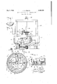
- Fig. 1 is a side elevation partly in section of the principal parts of my said invention
- Fig. 2 is a sectional view on line. 22 of Fig. 1;
- Fig. 3 is a sectional view on line 3-3 of Fig. 2; but in addition showing the rake partially broken away in elevation.
- a removable annular bottom plate '8 is'secured to the floor of tank 4 by bolts 9, said bottom plate, preferably madein four sections, being composed of manganese-steel or other abrasionresisting material, isprovided to form thebottom of an-annular mortar l-B, and at its center to provide a mercury well-H. increase in thickness of the outer portion of said bottom plates 8 is utilized to permit the sloping of its upper surface toward the center of the circle formed by its circumference.
- the outer annular area between the middle of the radiusand the periphery of said bottom plate -13 is provided with a series of diametric grooves l2 each of a width and depth relative to the'size ofthe ore to be ground, the remaining area of said "bottom plate 5 being smooth.
- the Wallet lower portion -5 of said tank above bottom plate 8 is lined with detachable hardenedsteel-plates 13, which may be similarly grooved, secured to the wall of said lowor tank-portion! by bolts I4.
- a pulley, adapted for "rotation by a source ofpower (notshown) is illustrated at l6 attachedto shaft H to the'opposite end of which pinion l8 is secured which meshes with beveled gear-l9 secured to vertical shaft which is retatably-supported in-a-suitable framework 2;! by a collar and thrust bearing assembly '22.
- Shaft 20 extends downwardly *through the 'top of the tank portion 6 where it is further provided with a suitable bearing 23.
- a rotor element 24 is mounted, consisting of an arm having near its ends series of holes 25-45,
- the sleds or shoes 26, each consisting of a base 28 and walls 2929 are formed of some abrasion-resisting material, such as manganese steel, said sleds conforming to the curvature of the interior of the annular channel-mortar.
- the front bottom edges of each of said sleds 26 are volume of water.
- Posts 32-32 are adapted to secure the weights within the sleds or shoes 26 as illustrated in Fig. 3.
- the speed at which the rotor arm is operated, increasing or decreasing the centrifugal force of the sleds, also obviously affects the pressure of the grinding surfaces.
- Drag rakes 3333 are attached in any suitable manner to each of sleds 25, being designed to stir and loosen the ground material.
- the operation of the device is asv follows: Ore, previously crushed to a suitable size, is flushed into the mill by approximately four times its Actuating mechanism to drag the sleds around in the mortar channel then being set in operation the sleds are caused to slide over the ore crushing and grinding it against the ribbed floor thereof, and by reason of the outward swing on the supporting drains, grinding particles of the ore between the outer walls of said sled and the side plates l3. As the ore is ground to a suitable fineness it is thrown into suspension and decanted through one of the variable discharge ports or openings 34.
- Free gold values by reason of the slope of the bottom plate 8 of the annular mortar Ill gradually settles or is worked toward the mercury well H in the center of tank 5 within the annular mortar channel, where released gold forms an amalgam.
- the ribbed upper surface of bottom plate 8 assists in the grinding of coarse pieces of ore, the tendency being for the finely ground particles of the gangue to be thrown into suspension while the free gold tends to gravitate toward the center.
- the rotary movement of the sled is communicated to the liquid contents of the tank, and the centrifugal force resulting from said rotation throws the ground material in suspension up over the amalgamation zone 1 where the fine or floured gold values become attached or amalgamated with the mercury of the amalgamation plate, which may be used to cover zone 1.
- variable discharge ports enable the operator to decant at levels where the fineness of the grind will meet the requirements of either flotation or cyanidation.
- the mill itself may consist essentially of a tank made of size %-inch boiler plate of a diameter varying from 2 to 8 feet and of a depth of from 30 to 40 inches, depending upon the grinding capacity desired.
- the bottom of the boiler plate tank is welded in a distance of approximately four inches and supported by heavy angle irons welded across the bottom.
- the bot tom manganese plates of the annular mortar l8 may be 1%; inches thick at the outer edge and slope to l inch at the center of the mill.
- These bottom plates may be grooved to a depth of inch and a width of inch, such grooves being inch apart and running from the periphery to the center, about one-half the width of the plate.
- the lower portion 5 of the tank may be lined to a height of 8 inches by the manganese side plates l3, which plates being detachable may be replaced from time to time as they become worn out, as is also true of the bottom liners 8.
- the flare of the lower tank at its connection with the upper tank by the zone '7 may be from 10 to 16 inches depending upon the capacity desired, its slope being at a rate from 1 to 4, and being covered by silver-ed copper amalgamation plates only where free milling gold values are to be recovered.
Landscapes
- Engineering & Computer Science (AREA)
- Food Science & Technology (AREA)
- Crushing And Grinding (AREA)
Description
Jan. 7, 1936. J. H. DEQUER DEVICE FOR MILLING AND SEPARATING ORES 4 Filed'Feb. 19, 1954 WWW w m .Q A WM 0 Patented Jan. 7, 1936 UNITED STATES PATENT OFFICE FDEYICE EOR MILLING AND S SEP-HRATING {GEES JohnHiDequer, Los Angeleaflalif.
:Application February 19, 1934, Serial No. 711,937
,1 Claim.
iMyrinvention relates to millsiadapted *for com- ;minuting, principally, precious metal bearing ores by crushing and braying :means .as a preliminary step to a recovery ofstheir valuable constituents; also involving :a specific adaptation of .:classifying amalgamating, floating or other well knownreducing means-or methods.
.A principal object of my said invention is to "provide a small, comparatively light and compact, easily transported, and inexpensive unit adapted for the usual'limited scale of operations of the individual miner or prospector for efsfecting the above :mentioned processes of ore treatment; and which may 'be efficientl-y utilized in the treatment of any kind and character of ore-in pursuance of :the general objects above mentioned.
It is also an important purpose of saidinvention to provide crushing and grinding :means 'which may be easily varied in accordance with the renitency of the material being treated 'by the'increase or decrease of =the-weights of pestlesleds or shoes, and :also to utilize the centrifugal force :createdjby a rotary travelling movement of said sleds not only for said grinding process but also for the classification of the --ore sands-by their specific gravity; and where free milling gold values are to'loe recoveredtoutilizesuch centrifugal force also to throw the ground material which is suspendedin waterwithin the tank containing said 'g-rinding mechanism up and over-a sloping amalgamation zone all as hereinafter specifically described.
:Other objects, such as simplicity and economy of construction, low initial cost, ease "andeconomyof operation, efliciency of action, and adaptability to a wide range of kinds of material to be treated, will be obvious to those of skill in the art to which this invention appertains, upon an examination of the detailed description to follow.
In the drawing, Fig. 1 is a side elevation partly in section of the principal parts of my said invention;
Fig. 2 is a sectional view on line. 22 of Fig. 1;
Fig. 3 is a sectional view on line 3-3 of Fig. 2; but in addition showing the rake partially broken away in elevation.
Referring with more particularity to the drawing, the numerals of which designate similar parts throughout the several views, 4 indicates a tank consisting of a lower part 5 and an upper part 6 of increased diameter, connected by flared portion forming an inwardly sloping annular ledge I, covered, when free milling gold values are to be. recovered, with asilvered copper "amal- 'gamation plate, the purpose of which will be hereafter described.
A removable annular bottom plate '8 is'secured to the floor of tank 4 by bolts 9, said bottom plate, preferably madein four sections, being composed of manganese-steel or other abrasionresisting material, isprovided to form thebottom of an-annular mortar l-B, and at its center to provide a mercury well-H. increase in thickness of the outer portion of said bottom plates 8 is utilized to permit the sloping of its upper surface toward the center of the circle formed by its circumference. The outer annular area between the middle of the radiusand the periphery of said bottom plate -13 is provided with a series of diametric grooves l2 each of a width and depth relative to the'size ofthe ore to be ground, the remaining area of said "bottom plate 5 being smooth. The Wallet lower portion -5 of said tank above bottom plate 8 is lined with detachable hardenedsteel-plates 13, which may be similarly grooved, secured to the wall of said lowor tank-portion! by bolts I4. I
I5 indicates the intake pipe through which ore, having been first crushed to suitable size,=is
carried to the annular mortar by a flower water, as later more specifically described, for grinding. A pulley, adapted for "rotation by a source ofpower (notshown) is illustrated at l6 attachedto shaft H to the'opposite end of which pinion l8 is secured which meshes with beveled gear-l9 secured to vertical shaft which is retatably-supported in-a-suitable framework 2;! by a collar and thrust bearing assembly '22. Shaft 20 extends downwardly *through the 'top of the tank portion 6 where it is further provided with a suitable bearing 23.
On the lower end of shaft 20, inside of tank 4, a rotor element 24 is mounted, consisting of an arm having near its ends series of holes 25-45,
which overhang the track for attachment of the pestle-sleds or shoes 26-26 as hereinafter described, said pestle-sleds being oppositely disposed in annular mortar I 0, by means of chains 21-21 so that as the arm is actuated by the rotation of the shaft to which it is connected the pastlesleds or shoes are dragged by said chains 21 around the annular channel of mortar Ill.
The sleds or shoes 26, each consisting of a base 28 and walls 2929 are formed of some abrasion-resisting material, such as manganese steel, said sleds conforming to the curvature of the interior of the annular channel-mortar. The front bottom edges of each of said sleds 26 are volume of water.
beveled as shown at 30 for the obvious purpose of permitting them to ride over the pieces of ore being ground.
Due to the fact that gold is found with a variety of associated elements having different qualities of hardness, means are provided to vary the pressure of the pestle-sleds or shoes 26 (in order to avoid excessive consumption of power in their motivation) consisting of a plurality of removable weights 3l-3l which may be applied to sleds 26 when necessary, depending on the renitency of the ore to be ground.
Posts 32-32 are adapted to secure the weights within the sleds or shoes 26 as illustrated in Fig. 3. The speed at which the rotor arm is operated, increasing or decreasing the centrifugal force of the sleds, also obviously affects the pressure of the grinding surfaces.
Drag rakes 3333, are attached in any suitable manner to each of sleds 25, being designed to stir and loosen the ground material.
34 indicates a series of discharge openings through which the fluid is decanted.
The operation of the device is asv follows: Ore, previously crushed to a suitable size, is flushed into the mill by approximately four times its Actuating mechanism to drag the sleds around in the mortar channel then being set in operation the sleds are caused to slide over the ore crushing and grinding it against the ribbed floor thereof, and by reason of the outward swing on the supporting drains, grinding particles of the ore between the outer walls of said sled and the side plates l3. As the ore is ground to a suitable fineness it is thrown into suspension and decanted through one of the variable discharge ports or openings 34.
Free gold values by reason of the slope of the bottom plate 8 of the annular mortar Ill gradually settles or is worked toward the mercury well H in the center of tank 5 within the annular mortar channel, where released gold forms an amalgam. The ribbed upper surface of bottom plate 8 assists in the grinding of coarse pieces of ore, the tendency being for the finely ground particles of the gangue to be thrown into suspension while the free gold tends to gravitate toward the center. The rotary movement of the sled is communicated to the liquid contents of the tank, and the centrifugal force resulting from said rotation throws the ground material in suspension up over the amalgamation zone 1 where the fine or floured gold values become attached or amalgamated with the mercury of the amalgamation plate, which may be used to cover zone 1.
The variable discharge ports enable the operator to decant at levels where the fineness of the grind will meet the requirements of either flotation or cyanidation.
While I do not limit myself to any particular dimensions, the following may be illustrative of a practical embodiment of my invention showing the extreme compactness which is an important object thereof.
The mill itself may consist essentially of a tank made of size %-inch boiler plate of a diameter varying from 2 to 8 feet and of a depth of from 30 to 40 inches, depending upon the grinding capacity desired. The bottom of the boiler plate tank is welded in a distance of approximately four inches and supported by heavy angle irons welded across the bottom. The bot tom manganese plates of the annular mortar l8 may be 1%; inches thick at the outer edge and slope to l inch at the center of the mill. These bottom plates may be grooved to a depth of inch and a width of inch, such grooves being inch apart and running from the periphery to the center, about one-half the width of the plate.
The lower portion 5 of the tank may be lined to a height of 8 inches by the manganese side plates l3, which plates being detachable may be replaced from time to time as they become worn out, as is also true of the bottom liners 8. The flare of the lower tank at its connection with the upper tank by the zone '7 may be from 10 to 16 inches depending upon the capacity desired, its slope being at a rate from 1 to 4, and being covered by silver-ed copper amalgamation plates only where free milling gold values are to be recovered.
Comparatively little power is needed to operate a device of the general capacity above indicated. A 1500-12,. P. M. motor of one horsepower per ton will be sufficient to actuate a 10 to 1 reducing worm gear, which in turn drives the pulley on the pinion shaft, the worm gear pulley is onehalf the size of the pinion pulley causing further reduction, which brings about a relatively slow rotarymotion of the sled.
What I claim and desire to secure by Letters Patent, is:
In a device for milling and separating ore, a
tank, an annular mortar with perpendicular cylindrical sides and an inwardly sloping bottom forming a channel extending around the bottom of said tank, radial grooves in the upper surface of the bottom of said mortar, pestle-sleds, means to increase the weight of said sleds, drag rakes attached to said sleds, and means to impel said sleds around said channel and over pieces of ore fed to said mortar.
JOHN H. DEQUER.
Priority Applications (1)
| Application Number | Priority Date | Filing Date | Title |
|---|---|---|---|
| US711937A US2026825A (en) | 1934-02-19 | 1934-02-19 | Device for milling and separating ores |
Applications Claiming Priority (1)
| Application Number | Priority Date | Filing Date | Title |
|---|---|---|---|
| US711937A US2026825A (en) | 1934-02-19 | 1934-02-19 | Device for milling and separating ores |
Publications (1)
| Publication Number | Publication Date |
|---|---|
| US2026825A true US2026825A (en) | 1936-01-07 |
Family
ID=24860118
Family Applications (1)
| Application Number | Title | Priority Date | Filing Date |
|---|---|---|---|
| US711937A Expired - Lifetime US2026825A (en) | 1934-02-19 | 1934-02-19 | Device for milling and separating ores |
Country Status (1)
| Country | Link |
|---|---|
| US (1) | US2026825A (en) |
Cited By (2)
| Publication number | Priority date | Publication date | Assignee | Title |
|---|---|---|---|---|
| US2514064A (en) * | 1949-05-06 | 1950-07-04 | A M Phippen | Ore milling and screening apparatus |
| WO2009052640A1 (en) * | 2007-10-25 | 2009-04-30 | Bühler AG | Cardanic doctor blade |
-
1934
- 1934-02-19 US US711937A patent/US2026825A/en not_active Expired - Lifetime
Cited By (2)
| Publication number | Priority date | Publication date | Assignee | Title |
|---|---|---|---|---|
| US2514064A (en) * | 1949-05-06 | 1950-07-04 | A M Phippen | Ore milling and screening apparatus |
| WO2009052640A1 (en) * | 2007-10-25 | 2009-04-30 | Bühler AG | Cardanic doctor blade |
Similar Documents
| Publication | Publication Date | Title |
|---|---|---|
| Richards | A text book of ore dressing | |
| Truscott | A text-book of ore dressing | |
| US2026825A (en) | Device for milling and separating ores | |
| US2115314A (en) | Ore mill | |
| US2132195A (en) | Apparatus for the recovery of precious metals such as gold | |
| US3729182A (en) | Process and apparatus for recovering precious metals | |
| US1772737A (en) | Ball mill | |
| US287256A (en) | Combined ore grinder and amalgamator | |
| US1163876A (en) | Apparatus for separating or classifying ores. | |
| US1476808A (en) | Amalgamator | |
| US466162A (en) | George eraser | |
| US2212467A (en) | Apparatus for separating minerals | |
| US26784A (en) | Gold-sepabatob | |
| US139556A (en) | Improvement in apparatus for separating, concentrating, and amalgamating ores | |
| US2134445A (en) | Amalgamator | |
| US618006A (en) | Apparatus for concentrating and amalgamating preciqu | |
| US617466A (en) | Apparatus for separating precious metals from their ores | |
| US521663A (en) | Ore grinder and amalgamator | |
| US1361723A (en) | Amalgamator | |
| US293936A (en) | becker | |
| US614401A (en) | And mary | |
| US1213264A (en) | Mortar ball-mill. | |
| US1558574A (en) | Centrifugal amalgamator | |
| US757205A (en) | Gold-separator. | |
| US121296A (en) | Improvement in apparatus for amalgamating gold in tailings |