US20090110907A1 - Membranes Based On Poly (Vinyl Alcohol-Co-Vinylamine) - Google Patents
Membranes Based On Poly (Vinyl Alcohol-Co-Vinylamine) Download PDFInfo
- Publication number
- US20090110907A1 US20090110907A1 US12/112,535 US11253508A US2009110907A1 US 20090110907 A1 US20090110907 A1 US 20090110907A1 US 11253508 A US11253508 A US 11253508A US 2009110907 A1 US2009110907 A1 US 2009110907A1
- Authority
- US
- United States
- Prior art keywords
- porous
- membrane
- inorganic
- vinylamine
- poly
- Prior art date
- Legal status (The legal status is an assumption and is not a legal conclusion. Google has not performed a legal analysis and makes no representation as to the accuracy of the status listed.)
- Abandoned
Links
- 239000012528 membrane Substances 0.000 title claims abstract description 256
- 125000000391 vinyl group Chemical group [H]C([*])=C([H])[H] 0.000 title claims abstract description 91
- 229920002554 vinyl polymer Polymers 0.000 title claims abstract description 91
- 229920005597 polymer membrane Polymers 0.000 claims abstract description 172
- 239000011148 porous material Substances 0.000 claims abstract description 109
- 229920000768 polyamine Polymers 0.000 claims abstract description 61
- 239000003431 cross linking reagent Substances 0.000 claims description 102
- 239000002243 precursor Substances 0.000 claims description 101
- 239000000203 mixture Substances 0.000 claims description 94
- 238000000034 method Methods 0.000 claims description 76
- 150000001412 amines Chemical class 0.000 claims description 55
- 229920000083 poly(allylamine) Polymers 0.000 claims description 44
- 238000000576 coating method Methods 0.000 claims description 33
- 239000011248 coating agent Substances 0.000 claims description 31
- 238000005266 casting Methods 0.000 claims description 13
- RLHGFJMGWQXPBW-UHFFFAOYSA-N 2-hydroxy-3-(1h-imidazol-5-ylmethyl)benzamide Chemical compound NC(=O)C1=CC=CC(CC=2NC=NC=2)=C1O RLHGFJMGWQXPBW-UHFFFAOYSA-N 0.000 claims description 3
- 239000010410 layer Substances 0.000 description 137
- 239000000243 solution Substances 0.000 description 63
- 239000000919 ceramic Substances 0.000 description 45
- WSFSSNUMVMOOMR-UHFFFAOYSA-N Formaldehyde Chemical compound O=C WSFSSNUMVMOOMR-UHFFFAOYSA-N 0.000 description 36
- 239000007789 gas Substances 0.000 description 34
- CURLTUGMZLYLDI-UHFFFAOYSA-N Carbon dioxide Chemical compound O=C=O CURLTUGMZLYLDI-UHFFFAOYSA-N 0.000 description 32
- 239000000758 substrate Substances 0.000 description 32
- PNEYBMLMFCGWSK-UHFFFAOYSA-N aluminium oxide Inorganic materials [O-2].[O-2].[O-2].[Al+3].[Al+3] PNEYBMLMFCGWSK-UHFFFAOYSA-N 0.000 description 26
- 229910002092 carbon dioxide Inorganic materials 0.000 description 23
- UYMKPFRHYYNDTL-UHFFFAOYSA-N ethenamine Chemical compound NC=C UYMKPFRHYYNDTL-UHFFFAOYSA-N 0.000 description 23
- 125000003277 amino group Chemical group 0.000 description 15
- 230000008569 process Effects 0.000 description 15
- 230000008901 benefit Effects 0.000 description 14
- 238000004132 cross linking Methods 0.000 description 13
- -1 polyvinylamines Polymers 0.000 description 13
- 239000007864 aqueous solution Substances 0.000 description 12
- 239000000463 material Substances 0.000 description 12
- 238000003756 stirring Methods 0.000 description 12
- XLYOFNOQVPJJNP-UHFFFAOYSA-N water Chemical compound O XLYOFNOQVPJJNP-UHFFFAOYSA-N 0.000 description 11
- 238000006243 chemical reaction Methods 0.000 description 10
- 239000011521 glass Substances 0.000 description 10
- 229920000642 polymer Polymers 0.000 description 10
- 239000001569 carbon dioxide Substances 0.000 description 9
- 238000000926 separation method Methods 0.000 description 9
- 229910001868 water Inorganic materials 0.000 description 9
- 239000002904 solvent Substances 0.000 description 8
- VYPSYNLAJGMNEJ-UHFFFAOYSA-N Silicium dioxide Chemical compound O=[Si]=O VYPSYNLAJGMNEJ-UHFFFAOYSA-N 0.000 description 7
- 150000001299 aldehydes Chemical class 0.000 description 7
- 229920001577 copolymer Polymers 0.000 description 7
- 230000008961 swelling Effects 0.000 description 7
- 238000012360 testing method Methods 0.000 description 7
- GWEVSGVZZGPLCZ-UHFFFAOYSA-N Titan oxide Chemical compound O=[Ti]=O GWEVSGVZZGPLCZ-UHFFFAOYSA-N 0.000 description 6
- MCMNRKCIXSYSNV-UHFFFAOYSA-N Zirconium dioxide Chemical compound O=[Zr]=O MCMNRKCIXSYSNV-UHFFFAOYSA-N 0.000 description 6
- 239000007788 liquid Substances 0.000 description 6
- 230000007246 mechanism Effects 0.000 description 6
- 238000002360 preparation method Methods 0.000 description 6
- 238000001878 scanning electron micrograph Methods 0.000 description 6
- 239000000126 substance Substances 0.000 description 6
- 239000004971 Cross linker Substances 0.000 description 5
- 239000010954 inorganic particle Substances 0.000 description 5
- 229910052751 metal Inorganic materials 0.000 description 5
- 239000002184 metal Substances 0.000 description 5
- 239000002245 particle Substances 0.000 description 5
- 150000003512 tertiary amines Chemical class 0.000 description 5
- OKTJSMMVPCPJKN-UHFFFAOYSA-N Carbon Chemical compound [C] OKTJSMMVPCPJKN-UHFFFAOYSA-N 0.000 description 4
- DHMQDGOQFOQNFH-UHFFFAOYSA-N Glycine Chemical compound NCC(O)=O DHMQDGOQFOQNFH-UHFFFAOYSA-N 0.000 description 4
- 229920002873 Polyethylenimine Polymers 0.000 description 4
- 239000004372 Polyvinyl alcohol Substances 0.000 description 4
- 239000002253 acid Substances 0.000 description 4
- 125000003118 aryl group Chemical group 0.000 description 4
- 229910052799 carbon Inorganic materials 0.000 description 4
- 239000006185 dispersion Substances 0.000 description 4
- 238000010438 heat treatment Methods 0.000 description 4
- 230000003993 interaction Effects 0.000 description 4
- 230000000670 limiting effect Effects 0.000 description 4
- 238000004519 manufacturing process Methods 0.000 description 4
- 125000001997 phenyl group Chemical group [H]C1=C([H])C([H])=C(*)C([H])=C1[H] 0.000 description 4
- 229920002451 polyvinyl alcohol Polymers 0.000 description 4
- 229940068984 polyvinyl alcohol Drugs 0.000 description 4
- 235000019422 polyvinyl alcohol Nutrition 0.000 description 4
- 150000003141 primary amines Chemical class 0.000 description 4
- 230000008929 regeneration Effects 0.000 description 4
- 238000011069 regeneration method Methods 0.000 description 4
- 229920005989 resin Polymers 0.000 description 4
- 239000011347 resin Substances 0.000 description 4
- 150000003839 salts Chemical class 0.000 description 4
- 125000000467 secondary amino group Chemical class [H]N([*:1])[*:2] 0.000 description 4
- 229910001220 stainless steel Inorganic materials 0.000 description 4
- 239000010935 stainless steel Substances 0.000 description 4
- 239000000725 suspension Substances 0.000 description 4
- 229910000505 Al2TiO5 Inorganic materials 0.000 description 3
- OADXCDYBFCINON-UHFFFAOYSA-N CC(C)(C)N=C=NC(C)(C)C1=CC=CC=C1.[H]N(C(=O)OCCOC)C(C)(C)C.[H]N(C(=O)OCCOC)C(C)(C)C1=CC=CC=C1 Chemical compound CC(C)(C)N=C=NC(C)(C)C1=CC=CC=C1.[H]N(C(=O)OCCOC)C(C)(C)C.[H]N(C(=O)OCCOC)C(C)(C)C1=CC=CC=C1 OADXCDYBFCINON-UHFFFAOYSA-N 0.000 description 3
- 0 CCC(CC(C)(C)C(**(C)(*)N(C)C)=O)N(CCC1)C1=O Chemical compound CCC(CC(C)(C)C(**(C)(*)N(C)C)=O)N(CCC1)C1=O 0.000 description 3
- LFQSCWFLJHTTHZ-UHFFFAOYSA-N Ethanol Chemical compound CCO LFQSCWFLJHTTHZ-UHFFFAOYSA-N 0.000 description 3
- 229910021536 Zeolite Inorganic materials 0.000 description 3
- 238000010521 absorption reaction Methods 0.000 description 3
- 125000000217 alkyl group Chemical group 0.000 description 3
- 230000015572 biosynthetic process Effects 0.000 description 3
- 229920001400 block copolymer Polymers 0.000 description 3
- VPKDCDLSJZCGKE-UHFFFAOYSA-N carbodiimide group Chemical group N=C=N VPKDCDLSJZCGKE-UHFFFAOYSA-N 0.000 description 3
- 125000002843 carboxylic acid group Chemical group 0.000 description 3
- CETPSERCERDGAM-UHFFFAOYSA-N ceric oxide Chemical compound O=[Ce]=O CETPSERCERDGAM-UHFFFAOYSA-N 0.000 description 3
- 229910000422 cerium(IV) oxide Inorganic materials 0.000 description 3
- KRKNYBCHXYNGOX-UHFFFAOYSA-N citric acid Chemical compound OC(=O)CC(O)(C(O)=O)CC(O)=O KRKNYBCHXYNGOX-UHFFFAOYSA-N 0.000 description 3
- 229910052878 cordierite Inorganic materials 0.000 description 3
- JSKIRARMQDRGJZ-UHFFFAOYSA-N dimagnesium dioxido-bis[(1-oxido-3-oxo-2,4,6,8,9-pentaoxa-1,3-disila-5,7-dialuminabicyclo[3.3.1]nonan-7-yl)oxy]silane Chemical compound [Mg++].[Mg++].[O-][Si]([O-])(O[Al]1O[Al]2O[Si](=O)O[Si]([O-])(O1)O2)O[Al]1O[Al]2O[Si](=O)O[Si]([O-])(O1)O2 JSKIRARMQDRGJZ-UHFFFAOYSA-N 0.000 description 3
- HNPSIPDUKPIQMN-UHFFFAOYSA-N dioxosilane;oxo(oxoalumanyloxy)alumane Chemical compound O=[Si]=O.O=[Al]O[Al]=O HNPSIPDUKPIQMN-UHFFFAOYSA-N 0.000 description 3
- KZHJGOXRZJKJNY-UHFFFAOYSA-N dioxosilane;oxo(oxoalumanyloxy)alumane Chemical compound O=[Si]=O.O=[Si]=O.O=[Al]O[Al]=O.O=[Al]O[Al]=O.O=[Al]O[Al]=O KZHJGOXRZJKJNY-UHFFFAOYSA-N 0.000 description 3
- 238000007598 dipping method Methods 0.000 description 3
- 238000001035 drying Methods 0.000 description 3
- 239000002241 glass-ceramic Substances 0.000 description 3
- 229920000578 graft copolymer Polymers 0.000 description 3
- 125000002496 methyl group Chemical group [H]C([H])([H])* 0.000 description 3
- 229910052863 mullite Inorganic materials 0.000 description 3
- 238000012856 packing Methods 0.000 description 3
- 238000010422 painting Methods 0.000 description 3
- 230000036961 partial effect Effects 0.000 description 3
- AABBHSMFGKYLKE-SNAWJCMRSA-N propan-2-yl (e)-but-2-enoate Chemical compound C\C=C\C(=O)OC(C)C AABBHSMFGKYLKE-SNAWJCMRSA-N 0.000 description 3
- 230000005855 radiation Effects 0.000 description 3
- 229920005604 random copolymer Polymers 0.000 description 3
- 239000012465 retentate Substances 0.000 description 3
- 239000000377 silicon dioxide Substances 0.000 description 3
- 238000005245 sintering Methods 0.000 description 3
- 238000004528 spin coating Methods 0.000 description 3
- 238000005507 spraying Methods 0.000 description 3
- 239000010457 zeolite Substances 0.000 description 3
- IJGRMHOSHXDMSA-UHFFFAOYSA-N Atomic nitrogen Chemical compound N#N IJGRMHOSHXDMSA-UHFFFAOYSA-N 0.000 description 2
- KCXVZYZYPLLWCC-UHFFFAOYSA-N EDTA Chemical compound OC(=O)CN(CC(O)=O)CCN(CC(O)=O)CC(O)=O KCXVZYZYPLLWCC-UHFFFAOYSA-N 0.000 description 2
- 239000004593 Epoxy Substances 0.000 description 2
- LYCAIKOWRPUZTN-UHFFFAOYSA-N Ethylene glycol Chemical compound OCCO LYCAIKOWRPUZTN-UHFFFAOYSA-N 0.000 description 2
- 238000001157 Fourier transform infrared spectrum Methods 0.000 description 2
- SXRSQZLOMIGNAQ-UHFFFAOYSA-N Glutaraldehyde Chemical compound O=CCCCC=O SXRSQZLOMIGNAQ-UHFFFAOYSA-N 0.000 description 2
- 239000004471 Glycine Substances 0.000 description 2
- HNDVDQJCIGZPNO-YFKPBYRVSA-N L-histidine Chemical compound OC(=O)[C@@H](N)CC1=CN=CN1 HNDVDQJCIGZPNO-YFKPBYRVSA-N 0.000 description 2
- CPLXHLVBOLITMK-UHFFFAOYSA-N Magnesium oxide Chemical compound [Mg]=O CPLXHLVBOLITMK-UHFFFAOYSA-N 0.000 description 2
- 238000007792 addition Methods 0.000 description 2
- 230000002411 adverse Effects 0.000 description 2
- 229910000323 aluminium silicate Inorganic materials 0.000 description 2
- 239000012298 atmosphere Substances 0.000 description 2
- 150000001718 carbodiimides Chemical class 0.000 description 2
- 238000010000 carbonizing Methods 0.000 description 2
- 239000003054 catalyst Substances 0.000 description 2
- 230000008859 change Effects 0.000 description 2
- 229920001688 coating polymer Polymers 0.000 description 2
- 238000001816 cooling Methods 0.000 description 2
- 238000005520 cutting process Methods 0.000 description 2
- 238000003618 dip coating Methods 0.000 description 2
- 238000005516 engineering process Methods 0.000 description 2
- 238000001125 extrusion Methods 0.000 description 2
- 238000010304 firing Methods 0.000 description 2
- 230000004907 flux Effects 0.000 description 2
- 238000002309 gasification Methods 0.000 description 2
- LEQAOMBKQFMDFZ-UHFFFAOYSA-N glyoxal Chemical compound O=CC=O LEQAOMBKQFMDFZ-UHFFFAOYSA-N 0.000 description 2
- 229960002885 histidine Drugs 0.000 description 2
- 229930195733 hydrocarbon Natural products 0.000 description 2
- 150000002430 hydrocarbons Chemical class 0.000 description 2
- 238000003384 imaging method Methods 0.000 description 2
- 239000012948 isocyanate Substances 0.000 description 2
- 150000002513 isocyanates Chemical class 0.000 description 2
- 229910044991 metal oxide Inorganic materials 0.000 description 2
- 150000004706 metal oxides Chemical class 0.000 description 2
- VNWKTOKETHGBQD-UHFFFAOYSA-N methane Chemical compound C VNWKTOKETHGBQD-UHFFFAOYSA-N 0.000 description 2
- 230000004048 modification Effects 0.000 description 2
- 238000012986 modification Methods 0.000 description 2
- 229910052757 nitrogen Inorganic materials 0.000 description 2
- 229910052760 oxygen Inorganic materials 0.000 description 2
- 239000012466 permeate Substances 0.000 description 2
- 238000005373 pervaporation Methods 0.000 description 2
- 229920000915 polyvinyl chloride Polymers 0.000 description 2
- 239000004800 polyvinyl chloride Substances 0.000 description 2
- 229920002717 polyvinylpyridine Polymers 0.000 description 2
- 239000000047 product Substances 0.000 description 2
- 238000009419 refurbishment Methods 0.000 description 2
- 229910052596 spinel Inorganic materials 0.000 description 2
- 239000011029 spinel Substances 0.000 description 2
- 238000007669 thermal treatment Methods 0.000 description 2
- 230000035899 viability Effects 0.000 description 2
- 230000004584 weight gain Effects 0.000 description 2
- 235000019786 weight gain Nutrition 0.000 description 2
- 229920002818 (Hydroxyethyl)methacrylate Polymers 0.000 description 1
- IVIDDMGBRCPGLJ-UHFFFAOYSA-N 2,3-bis(oxiran-2-ylmethoxy)propan-1-ol Chemical compound C1OC1COC(CO)COCC1CO1 IVIDDMGBRCPGLJ-UHFFFAOYSA-N 0.000 description 1
- GFISDBXSWQMOND-UHFFFAOYSA-N 2,5-dimethoxyoxolane Chemical compound COC1CCC(OC)O1 GFISDBXSWQMOND-UHFFFAOYSA-N 0.000 description 1
- HAZWONBCJXKAMF-UHFFFAOYSA-N 2-[1-[1,3-bis[2-(oxiran-2-ylmethoxy)propoxy]propan-2-yloxy]propan-2-yloxymethyl]oxirane Chemical compound C1OC1COC(C)COCC(OCC(C)OCC1OC1)COCC(C)OCC1CO1 HAZWONBCJXKAMF-UHFFFAOYSA-N 0.000 description 1
- KUAUJXBLDYVELT-UHFFFAOYSA-N 2-[[2,2-dimethyl-3-(oxiran-2-ylmethoxy)propoxy]methyl]oxirane Chemical compound C1OC1COCC(C)(C)COCC1CO1 KUAUJXBLDYVELT-UHFFFAOYSA-N 0.000 description 1
- 238000010146 3D printing Methods 0.000 description 1
- QCQCHGYLTSGIGX-GHXANHINSA-N 4-[[(3ar,5ar,5br,7ar,9s,11ar,11br,13as)-5a,5b,8,8,11a-pentamethyl-3a-[(5-methylpyridine-3-carbonyl)amino]-2-oxo-1-propan-2-yl-4,5,6,7,7a,9,10,11,11b,12,13,13a-dodecahydro-3h-cyclopenta[a]chrysen-9-yl]oxy]-2,2-dimethyl-4-oxobutanoic acid Chemical compound N([C@@]12CC[C@@]3(C)[C@]4(C)CC[C@H]5C(C)(C)[C@@H](OC(=O)CC(C)(C)C(O)=O)CC[C@]5(C)[C@H]4CC[C@@H]3C1=C(C(C2)=O)C(C)C)C(=O)C1=CN=CC(C)=C1 QCQCHGYLTSGIGX-GHXANHINSA-N 0.000 description 1
- IBEUEXKFVGJSDL-UHFFFAOYSA-N 4-hydroxy-5-methyl-1,3-diazinan-2-one Chemical compound CC1CNC(=O)NC1O IBEUEXKFVGJSDL-UHFFFAOYSA-N 0.000 description 1
- KWSLGOVYXMQPPX-UHFFFAOYSA-N 5-[3-(trifluoromethyl)phenyl]-2h-tetrazole Chemical compound FC(F)(F)C1=CC=CC(C2=NNN=N2)=C1 KWSLGOVYXMQPPX-UHFFFAOYSA-N 0.000 description 1
- 239000004475 Arginine Substances 0.000 description 1
- 239000002028 Biomass Substances 0.000 description 1
- WRAGBEWQGHCDDU-UHFFFAOYSA-M C([O-])([O-])=O.[NH4+].[Zr+] Chemical compound C([O-])([O-])=O.[NH4+].[Zr+] WRAGBEWQGHCDDU-UHFFFAOYSA-M 0.000 description 1
- WMQGCOVRWBVURV-UHFFFAOYSA-N C.C.C.C.CCCN(CCN(C)CCCCNC)CCN(CCO)CCN(CCO)CCO Chemical compound C.C.C.C.CCCN(CCN(C)CCCCNC)CCN(CCO)CCN(CCO)CCO WMQGCOVRWBVURV-UHFFFAOYSA-N 0.000 description 1
- GSONUQIBQJHTMA-UHFFFAOYSA-O C.C.CCC(CC1C[N+](C)(C)CC1CC)C(N)=O.[Cl-] Chemical compound C.C.CCC(CC1C[N+](C)(C)CC1CC)C(N)=O.[Cl-] GSONUQIBQJHTMA-UHFFFAOYSA-O 0.000 description 1
- NYWRUBHEOXWNNF-UHFFFAOYSA-N C.CC1=NC(N2CCOCC2)=NC(N(CCCCCCN(C)C2CC(C)(C)CC(C)(C)C2)C2CC(C)(C)CC(C)(C)C2)=N1 Chemical compound C.CC1=NC(N2CCOCC2)=NC(N(CCCCCCN(C)C2CC(C)(C)CC(C)(C)C2)C2CC(C)(C)CC(C)(C)C2)=N1 NYWRUBHEOXWNNF-UHFFFAOYSA-N 0.000 description 1
- NTKDVRBUEYPNMX-UHFFFAOYSA-N C1OC1C1CO1.CC.CC.CC.O=C1CCC(=O)O1.O=C1CCC(=O)O1.O=C1CCCO1.O=C1CCCO1.O=C=NN=C=O.O=CC=O Chemical compound C1OC1C1CO1.CC.CC.CC.O=C1CCC(=O)O1.O=C1CCC(=O)O1.O=C1CCCO1.O=C1CCCO1.O=C=NN=C=O.O=CC=O NTKDVRBUEYPNMX-UHFFFAOYSA-N 0.000 description 1
- OGQOAXBVENQVNR-UHFFFAOYSA-N CC.CCC(CC(C)C(=O)CCN(C)C)N1CCCC1=O Chemical compound CC.CCC(CC(C)C(=O)CCN(C)C)N1CCCC1=O OGQOAXBVENQVNR-UHFFFAOYSA-N 0.000 description 1
- YHIZZSLGMMCSNN-UHFFFAOYSA-N CCC(O)CC(C)N Chemical compound CCC(O)CC(C)N YHIZZSLGMMCSNN-UHFFFAOYSA-N 0.000 description 1
- LDYTVHIKTYWDBL-UHFFFAOYSA-N CCC1C[N+](C)(C)CC1CC Chemical compound CCC1C[N+](C)(C)CC1CC LDYTVHIKTYWDBL-UHFFFAOYSA-N 0.000 description 1
- UGFAIRIUMAVXCW-UHFFFAOYSA-N Carbon monoxide Chemical compound [O+]#[C-] UGFAIRIUMAVXCW-UHFFFAOYSA-N 0.000 description 1
- 229920013683 Celanese Polymers 0.000 description 1
- VEXZGXHMUGYJMC-UHFFFAOYSA-M Chloride anion Chemical compound [Cl-] VEXZGXHMUGYJMC-UHFFFAOYSA-M 0.000 description 1
- KDXKERNSBIXSRK-RXMQYKEDSA-N D-lysine Chemical compound NCCCC[C@@H](N)C(O)=O KDXKERNSBIXSRK-RXMQYKEDSA-N 0.000 description 1
- BRLQWZUYTZBJKN-UHFFFAOYSA-N Epichlorohydrin Chemical compound ClCC1CO1 BRLQWZUYTZBJKN-UHFFFAOYSA-N 0.000 description 1
- CPELXLSAUQHCOX-UHFFFAOYSA-N Hydrogen bromide Chemical class Br CPELXLSAUQHCOX-UHFFFAOYSA-N 0.000 description 1
- QNAYBMKLOCPYGJ-REOHCLBHSA-N L-alanine Chemical compound C[C@H](N)C(O)=O QNAYBMKLOCPYGJ-REOHCLBHSA-N 0.000 description 1
- ODKSFYDXXFIFQN-BYPYZUCNSA-P L-argininium(2+) Chemical compound NC(=[NH2+])NCCC[C@H]([NH3+])C(O)=O ODKSFYDXXFIFQN-BYPYZUCNSA-P 0.000 description 1
- KDXKERNSBIXSRK-YFKPBYRVSA-N L-lysine Chemical compound NCCCC[C@H](N)C(O)=O KDXKERNSBIXSRK-YFKPBYRVSA-N 0.000 description 1
- 229910000502 Li-aluminosilicate Inorganic materials 0.000 description 1
- KDXKERNSBIXSRK-UHFFFAOYSA-N Lysine Natural products NCCCCC(N)C(O)=O KDXKERNSBIXSRK-UHFFFAOYSA-N 0.000 description 1
- 239000004472 Lysine Substances 0.000 description 1
- FYYHWMGAXLPEAU-UHFFFAOYSA-N Magnesium Chemical compound [Mg] FYYHWMGAXLPEAU-UHFFFAOYSA-N 0.000 description 1
- WSMYVTOQOOLQHP-UHFFFAOYSA-N Malondialdehyde Chemical compound O=CCC=O WSMYVTOQOOLQHP-UHFFFAOYSA-N 0.000 description 1
- 229920000877 Melamine resin Polymers 0.000 description 1
- 238000006845 Michael addition reaction Methods 0.000 description 1
- FFDGPVCHZBVARC-UHFFFAOYSA-N N,N-dimethylglycine Chemical compound CN(C)CC(O)=O FFDGPVCHZBVARC-UHFFFAOYSA-N 0.000 description 1
- ZBBFHMBHRRUFGI-UHFFFAOYSA-N NCCCN(CCCN)CCCN(CCCN(CCCN)CCCN)CCCN(CCCN(CCCN(CCCN)CCCN)CCCN(CCCN)CCCN)CCN(CCCN(CCN(CCCN(CCCN(CCCN)CCCN)CCCN(CCCN)CCCN)CCCN(CCCN(CCCN)CCCN)CCCN(CCCN)CCCN)CCN(CCCN(CCCN(CCCN)CCCN)CCCN(CCCN)CCCN)CCCN(CCCN(CCCN)CCCN)CCCN(CCCN)CCCN)CCN(CCCN(CCCN(CCCN)CCCN)CCCN(CCCN)CCCN)CCCN(CCCN(CCCN)CCCN)CCCN(CCCN)CCCN Chemical compound NCCCN(CCCN)CCCN(CCCN(CCCN)CCCN)CCCN(CCCN(CCCN(CCCN)CCCN)CCCN(CCCN)CCCN)CCN(CCCN(CCN(CCCN(CCCN(CCCN)CCCN)CCCN(CCCN)CCCN)CCCN(CCCN(CCCN)CCCN)CCCN(CCCN)CCCN)CCN(CCCN(CCCN(CCCN)CCCN)CCCN(CCCN)CCCN)CCCN(CCCN(CCCN)CCCN)CCCN(CCCN)CCCN)CCN(CCCN(CCCN(CCCN)CCCN)CCCN(CCCN)CCCN)CCCN(CCCN(CCCN)CCCN)CCCN(CCCN)CCCN ZBBFHMBHRRUFGI-UHFFFAOYSA-N 0.000 description 1
- 229910021202 NaH2PO2.H2O Inorganic materials 0.000 description 1
- 239000004677 Nylon Substances 0.000 description 1
- 239000004642 Polyimide Substances 0.000 description 1
- 239000004793 Polystyrene Substances 0.000 description 1
- OFOBLEOULBTSOW-UHFFFAOYSA-N Propanedioic acid Natural products OC(=O)CC(O)=O OFOBLEOULBTSOW-UHFFFAOYSA-N 0.000 description 1
- 229920002125 Sokalan® Polymers 0.000 description 1
- 239000002250 absorbent Substances 0.000 description 1
- 230000002745 absorbent Effects 0.000 description 1
- 230000002378 acidificating effect Effects 0.000 description 1
- NIXOWILDQLNWCW-UHFFFAOYSA-N acrylic acid group Chemical group C(C=C)(=O)O NIXOWILDQLNWCW-UHFFFAOYSA-N 0.000 description 1
- 235000004279 alanine Nutrition 0.000 description 1
- 125000003172 aldehyde group Chemical group 0.000 description 1
- 229940024606 amino acid Drugs 0.000 description 1
- 235000001014 amino acid Nutrition 0.000 description 1
- 150000001413 amino acids Chemical class 0.000 description 1
- 150000003863 ammonium salts Chemical class 0.000 description 1
- ODKSFYDXXFIFQN-UHFFFAOYSA-N arginine Natural products OC(=O)C(N)CCCNC(N)=N ODKSFYDXXFIFQN-UHFFFAOYSA-N 0.000 description 1
- 125000003710 aryl alkyl group Chemical group 0.000 description 1
- QVGXLLKOCUKJST-UHFFFAOYSA-N atomic oxygen Chemical compound [O] QVGXLLKOCUKJST-UHFFFAOYSA-N 0.000 description 1
- 238000001354 calcination Methods 0.000 description 1
- 150000004657 carbamic acid derivatives Chemical class 0.000 description 1
- 229910002091 carbon monoxide Inorganic materials 0.000 description 1
- 239000003245 coal Substances 0.000 description 1
- 239000011247 coating layer Substances 0.000 description 1
- 150000001875 compounds Chemical class 0.000 description 1
- 230000003247 decreasing effect Effects 0.000 description 1
- 239000008367 deionised water Substances 0.000 description 1
- 229910021641 deionized water Inorganic materials 0.000 description 1
- 239000000412 dendrimer Substances 0.000 description 1
- 229920000736 dendritic polymer Polymers 0.000 description 1
- 238000000151 deposition Methods 0.000 description 1
- 230000008021 deposition Effects 0.000 description 1
- GYZLOYUZLJXAJU-UHFFFAOYSA-N diglycidyl ether Chemical compound C1OC1COCC1CO1 GYZLOYUZLJXAJU-UHFFFAOYSA-N 0.000 description 1
- 108700003601 dimethylglycine Proteins 0.000 description 1
- 238000004090 dissolution Methods 0.000 description 1
- 230000000694 effects Effects 0.000 description 1
- 230000005670 electromagnetic radiation Effects 0.000 description 1
- 125000003700 epoxy group Chemical group 0.000 description 1
- CCIVGXIOQKPBKL-UHFFFAOYSA-M ethanesulfonate Chemical compound CCS([O-])(=O)=O CCIVGXIOQKPBKL-UHFFFAOYSA-M 0.000 description 1
- CEIPQQODRKXDSB-UHFFFAOYSA-N ethyl 3-(6-hydroxynaphthalen-2-yl)-1H-indazole-5-carboximidate dihydrochloride Chemical compound Cl.Cl.C1=C(O)C=CC2=CC(C3=NNC4=CC=C(C=C43)C(=N)OCC)=CC=C21 CEIPQQODRKXDSB-UHFFFAOYSA-N 0.000 description 1
- 238000002474 experimental method Methods 0.000 description 1
- 239000010433 feldspar Substances 0.000 description 1
- IVJISJACKSSFGE-UHFFFAOYSA-N formaldehyde;1,3,5-triazine-2,4,6-triamine Chemical compound O=C.NC1=NC(N)=NC(N)=N1 IVJISJACKSSFGE-UHFFFAOYSA-N 0.000 description 1
- 125000000524 functional group Chemical group 0.000 description 1
- 239000005350 fused silica glass Substances 0.000 description 1
- 150000002332 glycine derivatives Chemical class 0.000 description 1
- 229940015043 glyoxal Drugs 0.000 description 1
- 150000002357 guanidines Chemical class 0.000 description 1
- HNDVDQJCIGZPNO-UHFFFAOYSA-N histidine Natural products OC(=O)C(N)CC1=CN=CN1 HNDVDQJCIGZPNO-UHFFFAOYSA-N 0.000 description 1
- 150000002429 hydrazines Chemical class 0.000 description 1
- 239000001257 hydrogen Substances 0.000 description 1
- 229910052739 hydrogen Inorganic materials 0.000 description 1
- 125000004435 hydrogen atom Chemical class [H]* 0.000 description 1
- WGCNASOHLSPBMP-UHFFFAOYSA-N hydroxyacetaldehyde Natural products OCC=O WGCNASOHLSPBMP-UHFFFAOYSA-N 0.000 description 1
- 150000002463 imidates Chemical class 0.000 description 1
- 239000004615 ingredient Substances 0.000 description 1
- IQPQWNKOIGAROB-UHFFFAOYSA-N isocyanate group Chemical group [N-]=C=O IQPQWNKOIGAROB-UHFFFAOYSA-N 0.000 description 1
- 239000011777 magnesium Substances 0.000 description 1
- 229910052749 magnesium Inorganic materials 0.000 description 1
- 239000000395 magnesium oxide Substances 0.000 description 1
- VZCYOOQTPOCHFL-UPHRSURJSA-N maleic acid Chemical compound OC(=O)\C=C/C(O)=O VZCYOOQTPOCHFL-UPHRSURJSA-N 0.000 description 1
- 239000011976 maleic acid Substances 0.000 description 1
- 238000002844 melting Methods 0.000 description 1
- 230000008018 melting Effects 0.000 description 1
- 150000001247 metal acetylides Chemical class 0.000 description 1
- 150000002739 metals Chemical class 0.000 description 1
- WSFSSNUMVMOOMR-NJFSPNSNSA-N methanone Chemical compound O=[14CH2] WSFSSNUMVMOOMR-NJFSPNSNSA-N 0.000 description 1
- 238000002156 mixing Methods 0.000 description 1
- 239000000178 monomer Substances 0.000 description 1
- 238000000465 moulding Methods 0.000 description 1
- OMNKZBIFPJNNIO-UHFFFAOYSA-N n-(2-methyl-4-oxopentan-2-yl)prop-2-enamide Chemical compound CC(=O)CC(C)(C)NC(=O)C=C OMNKZBIFPJNNIO-UHFFFAOYSA-N 0.000 description 1
- 238000001728 nano-filtration Methods 0.000 description 1
- 239000003345 natural gas Substances 0.000 description 1
- 150000004767 nitrides Chemical class 0.000 description 1
- 229920001778 nylon Polymers 0.000 description 1
- 239000011368 organic material Substances 0.000 description 1
- 239000003960 organic solvent Substances 0.000 description 1
- 230000003647 oxidation Effects 0.000 description 1
- 238000007254 oxidation reaction Methods 0.000 description 1
- 239000001254 oxidized starch Substances 0.000 description 1
- 235000013808 oxidized starch Nutrition 0.000 description 1
- 239000001301 oxygen Substances 0.000 description 1
- 230000035699 permeability Effects 0.000 description 1
- 229920000885 poly(2-vinylpyridine) Polymers 0.000 description 1
- 229920000075 poly(4-vinylpyridine) Polymers 0.000 description 1
- 229920000724 poly(L-arginine) polymer Polymers 0.000 description 1
- 229920002006 poly(N-vinylimidazole) polymer Polymers 0.000 description 1
- 229920000712 poly(acrylamide-co-diallyldimethylammonium chloride) Polymers 0.000 description 1
- 229920001308 poly(aminoacid) Polymers 0.000 description 1
- 229920000371 poly(diallyldimethylammonium chloride) polymer Polymers 0.000 description 1
- 229920000647 polyepoxide Polymers 0.000 description 1
- 229920000728 polyester Polymers 0.000 description 1
- 229920006267 polyester film Polymers 0.000 description 1
- 229920001721 polyimide Polymers 0.000 description 1
- 239000013047 polymeric layer Substances 0.000 description 1
- 229920000098 polyolefin Polymers 0.000 description 1
- 229920002223 polystyrene Polymers 0.000 description 1
- 229910052573 porcelain Inorganic materials 0.000 description 1
- GZWNUORNEQHOAW-UHFFFAOYSA-M potassium;2-aminoacetate Chemical compound [K+].NCC([O-])=O GZWNUORNEQHOAW-UHFFFAOYSA-M 0.000 description 1
- 230000003334 potential effect Effects 0.000 description 1
- 150000003242 quaternary ammonium salts Chemical class 0.000 description 1
- 230000007420 reactivation Effects 0.000 description 1
- 230000009257 reactivity Effects 0.000 description 1
- 230000002829 reductive effect Effects 0.000 description 1
- 229920006395 saturated elastomer Polymers 0.000 description 1
- 230000009919 sequestration Effects 0.000 description 1
- 150000004760 silicates Chemical class 0.000 description 1
- 229910052710 silicon Inorganic materials 0.000 description 1
- 239000010703 silicon Substances 0.000 description 1
- 229910010271 silicon carbide Inorganic materials 0.000 description 1
- 238000002791 soaking Methods 0.000 description 1
- 229910001379 sodium hypophosphite Inorganic materials 0.000 description 1
- WUWHFEHKUQVYLF-UHFFFAOYSA-M sodium;2-aminoacetate Chemical compound [Na+].NCC([O-])=O WUWHFEHKUQVYLF-UHFFFAOYSA-M 0.000 description 1
- 238000009987 spinning Methods 0.000 description 1
- 238000000629 steam reforming Methods 0.000 description 1
- 238000006467 substitution reaction Methods 0.000 description 1
- 239000000454 talc Substances 0.000 description 1
- 229910052623 talc Inorganic materials 0.000 description 1
- KUCOHFSKRZZVRO-UHFFFAOYSA-N terephthalaldehyde Chemical compound O=CC1=CC=C(C=O)C=C1 KUCOHFSKRZZVRO-UHFFFAOYSA-N 0.000 description 1
- 229920001897 terpolymer Polymers 0.000 description 1
- VZCYOOQTPOCHFL-UHFFFAOYSA-N trans-butenedioic acid Natural products OC(=O)C=CC(O)=O VZCYOOQTPOCHFL-UHFFFAOYSA-N 0.000 description 1
- 230000005641 tunneling Effects 0.000 description 1
- 229910052845 zircon Inorganic materials 0.000 description 1
- GFQYVLUOOAAOGM-UHFFFAOYSA-N zirconium(iv) silicate Chemical compound [Zr+4].[O-][Si]([O-])([O-])[O-] GFQYVLUOOAAOGM-UHFFFAOYSA-N 0.000 description 1
Images


Classifications
-
- B—PERFORMING OPERATIONS; TRANSPORTING
- B01—PHYSICAL OR CHEMICAL PROCESSES OR APPARATUS IN GENERAL
- B01D—SEPARATION
- B01D53/00—Separation of gases or vapours; Recovering vapours of volatile solvents from gases; Chemical or biological purification of waste gases, e.g. engine exhaust gases, smoke, fumes, flue gases, aerosols
- B01D53/22—Separation of gases or vapours; Recovering vapours of volatile solvents from gases; Chemical or biological purification of waste gases, e.g. engine exhaust gases, smoke, fumes, flue gases, aerosols by diffusion
- B01D53/228—Separation of gases or vapours; Recovering vapours of volatile solvents from gases; Chemical or biological purification of waste gases, e.g. engine exhaust gases, smoke, fumes, flue gases, aerosols by diffusion characterised by specific membranes
-
- B—PERFORMING OPERATIONS; TRANSPORTING
- B01—PHYSICAL OR CHEMICAL PROCESSES OR APPARATUS IN GENERAL
- B01D—SEPARATION
- B01D63/00—Apparatus in general for separation processes using semi-permeable membranes
- B01D63/06—Tubular membrane modules
- B01D63/066—Tubular membrane modules with a porous block having membrane coated passages
-
- B—PERFORMING OPERATIONS; TRANSPORTING
- B01—PHYSICAL OR CHEMICAL PROCESSES OR APPARATUS IN GENERAL
- B01D—SEPARATION
- B01D71/00—Semi-permeable membranes for separation processes or apparatus characterised by the material; Manufacturing processes specially adapted therefor
- B01D71/06—Organic material
- B01D71/38—Polyalkenylalcohols; Polyalkenylesters; Polyalkenylethers; Polyalkenylaldehydes; Polyalkenylketones; Polyalkenylacetals; Polyalkenylketals
-
- B—PERFORMING OPERATIONS; TRANSPORTING
- B01—PHYSICAL OR CHEMICAL PROCESSES OR APPARATUS IN GENERAL
- B01D—SEPARATION
- B01D2323/00—Details relating to membrane preparation
- B01D2323/30—Cross-linking
-
- Y—GENERAL TAGGING OF NEW TECHNOLOGICAL DEVELOPMENTS; GENERAL TAGGING OF CROSS-SECTIONAL TECHNOLOGIES SPANNING OVER SEVERAL SECTIONS OF THE IPC; TECHNICAL SUBJECTS COVERED BY FORMER USPC CROSS-REFERENCE ART COLLECTIONS [XRACs] AND DIGESTS
- Y10—TECHNICAL SUBJECTS COVERED BY FORMER USPC
- Y10T—TECHNICAL SUBJECTS COVERED BY FORMER US CLASSIFICATION
- Y10T428/00—Stock material or miscellaneous articles
- Y10T428/249921—Web or sheet containing structurally defined element or component
- Y10T428/249953—Composite having voids in a component [e.g., porous, cellular, etc.]
- Y10T428/249978—Voids specified as micro
- Y10T428/24998—Composite has more than two layers
Definitions
- the present invention relates, generally, to membranes and, more particularly, to membranes based on poly(vinyl alcohol-co-vinylamine) that can be used, for example, for molecular level separations and to methods for making the same.
- One process commonly used in the industry today to remove CO 2 from those gas mixtures involves the use of amine-based gas scrubbers.
- the gas mixture is contacted with an amine-containing organic solvent or an amine-containing solution.
- CO 2 and other acidic molecules, such as H 2 S, are selectively absorbed in the amine solution.
- the process takes advantage of the strong interaction between the amine, a base, and the CO 2 , an acid, leading to formation of a carbamate salt, as shown in FIG. 1 .
- the amine absorption technique has notable drawbacks and inefficiencies.
- the amine absorption technique requires a large amount of aqueous amine solution.
- the technique also requires a pump and an amine/CO 2 regeneration system, because, once the amine solution is saturated, it needs to be reactivated. Reactivation involves the removal of the bound CO 2 from the amine groups in the solution, and this process uses large amounts of energy.
- the amine absorption technique can corrode equipment, and the amine solution loses viability over a short period of time.
- Polymer membrane technology makes the process simpler while still utilizing the chemistry between the amino group and the CO 2 molecule. Not only does the use of polymer membrane technology make such a complex system as mentioned above unnecessary, it also overcomes problems associated with the need for regeneration and the loss of viability of the amine solution.
- the present invention relates to a polymer membrane that includes crosslinked poly(vinyl alcohol-co-vinylamine), wherein the membrane is non-porous or wherein the membrane is porous with pores having a median pore size of 300 nm or less.
- the present invention also relates to a polymer membrane that includes crosslinked poly(vinyl alcohol-co-vinylamine), wherein the polymer membrane further comprises a second polyamine and wherein the poly(vinyl alcohol-co-vinylamine) and the second polyamine are crosslinked with one another.
- the present invention also relates to a method for preparing a polymer membrane that includes crosslinked poly(vinyl alcohol-co-vinylamine), wherein the membrane is non-porous or wherein the membrane is porous with pores having a median pore size of 300 nm or less.
- the method includes providing a membrane precursor composition comprising a poly(vinyl alcohol-co-vinylamine) and a crosslinking agent; casting the membrane precursor composition in the form of a film; and curing the film under conditions effective for the crosslinking agent to crosslink the poly(vinyl alcohol-co-vinylamine).
- the present invention also relates to a method for preparing a polymer membrane that includes crosslinked poly(vinyl alcohol-co-vinylamine) and a second polyamine in which the poly(vinyl alcohol-co-vinylamine) and the second polyamine are crosslinked with one another.
- the method includes providing a membrane precursor composition comprising a poly(vinyl alcohol-co-vinylamine) and a crosslinking agent; casting the membrane precursor composition in the form of a film; and curing the film under conditions effective for the crosslinking agent to crosslink the poly(vinyl alcohol-co-vinylamine), wherein the membrane precursor composition further comprises a second polyamine and wherein the film is cured under conditions effective for the crosslinking agent to crosslink the poly(vinyl alcohol-co-vinylamine) and the second polyamine with one another.
- the present invention also relates to a hybrid membrane structure that includes:
- an inorganic porous support including a first end, a second end, and a plurality of inner channels having surfaces defined by porous walls and extending through the support from the first end to the second end;
- the inner channel surfaces of the inorganic porous support have a median pore size of 500 nanometers or less and the polymer membrane coats the inner channel surfaces of the inorganic porous support; and wherein, when the hybrid membrane structure includes the one or more porous inorganic intermediate layers, the polymer membrane coats the surface of the one or more porous intermediate layers.
- the present invention also relates to a hybrid membrane structure that includes:
- an inorganic porous support including a first end, a second end, and a plurality of inner channels having surfaces defined by porous walls and extending through the support from the first end to the second end;
- a polymer membrane that includes crosslinked poly(vinyl alcohol-co-vinylamine), wherein the membrane is non-porous or wherein the membrane is porous with pores having a median pore size of 300 nm or less; wherein, when the hybrid membrane structure does not include the one or more porous inorganic intermediate layers, the polymer membrane coats the inner channel surfaces of the inorganic porous support and wherein, when the hybrid membrane structure includes the one or more porous inorganic intermediate layers, the polymer membrane coats the surface of the one or more porous intermediate layers.
- the present invention also relates to a hybrid membrane structure that includes:
- an inorganic porous support including a first end, a second end, and a plurality of inner channels having surfaces defined by porous walls and extending through the support from the first end to the second end;
- a polymer membrane that includes crosslinked poly(vinyl alcohol-co-vinylamine), wherein the polymer membrane further includes a second polyamine and wherein the poly(vinyl alcohol-co-vinylamine) and the second polyamine are crosslinked with one another; wherein, when the hybrid membrane structure does not include the one or more porous inorganic intermediate layers, the polymer membrane coats the inner channel surfaces of the inorganic porous support and wherein, when the hybrid membrane structure includes the one or more porous inorganic intermediate layers, the polymer membrane coats the surface of the one or more porous intermediate layers.
- the present invention also relates to a membrane precursor composition that includes a poly(vinyl alcohol-co-vinylamine); a second polyamine; and a crosslinking agent.
- the present invention also relates to a method for making a hybrid membrane structure.
- the method includes:
- an inorganic porous support including a first end, a second end, and a plurality of inner channels having surfaces defined by porous walls and extending through the support from the first end to the second end; optionally applying one or more porous inorganic intermediate layers to the inner channel surfaces of the inorganic porous support;
- a membrane precursor composition that includes a poly(vinyl alcohol-co-vinylamine) and a crosslinking agent; wherein, when the one or more porous inorganic intermediate layers have not been applied to the inorganic porous support's inner channel surfaces, the inner channel surfaces of the inorganic porous support have a median pore size of 500 nanometers or less and the membrane precursor composition is applied to the inner channel surfaces of the inorganic porous support; and wherein, when the one or more porous inorganic intermediate layers have been applied to the inorganic porous support's inner channel surfaces, the membrane precursor composition is applied to the surface of the one or more porous intermediate layers; and
- the present invention also relates to a method for making a hybrid membrane structure.
- the method includes:
- an inorganic porous support including a first end, a second end, and a plurality of inner channels having surfaces defined by porous walls and extending through the support from the first end to the second end;
- a membrane precursor composition that includes a poly(vinyl alcohol-co-vinylamine), a second polyamine, and a crosslinking agent; wherein, when the one or more porous inorganic intermediate layers have not been applied to the inorganic porous support's inner channel surfaces, the membrane precursor composition is applied to the inner channel surfaces of the inorganic porous support; and wherein, when the one or more porous inorganic intermediate layers have been applied to the inorganic porous support's inner channel surfaces, the membrane precursor composition is applied to the surface of the one or more porous intermediate layers; and
- the membrane precursor composition under conditions effective for the crosslinking agent to crosslink the poly(vinyl alcohol-co-vinylamine) and the second polyamine with one another.
- the present invention also relates to a membrane precursor composition that includes a poly(vinyl alcohol-co-vinylamine); a second polyamine; and a crosslinking agent.
- the present invention also relates to a method for making a hybrid membrane structure.
- the method includes:
- an inorganic porous support including a first end, a second end, and a plurality of inner channels having surfaces defined by porous walls and extending through the support from the first end to the second end;
- a membrane precursor composition that includes a poly(vinyl alcohol-co-vinylamine) and a crosslinking agent; wherein, when the one or more porous inorganic intermediate layers have not been applied to the inorganic porous support's inner channel surfaces, the membrane precursor composition is applied to the inner channel surfaces of the inorganic porous support; and wherein, when the one or more porous inorganic intermediate layers have been applied to the inorganic porous support's inner channel surfaces, the membrane precursor composition is applied to the surface of the one or more porous intermediate layers; and
- the membrane precursor composition under conditions effective for the crosslinking agent to crosslink the poly(vinyl alcohol-co-vinylamine) into a membrane which is non-porous or which is porous with pores having a median pore size of 300 nm or less.
- FIG. 1 is a scheme showing the general interaction between CO 2 and amines.
- FIGS. 2A and 2B are schematic representations of a hybrid membrane structure according to the present invention.
- FIG. 2A is a perspective view
- FIG. 2B is a longitudinal cross-sectional view of the hybrid membrane structure shown in FIG. 2A taken through FIG. 2 A's Plane A.
- FIG. 3 is a longitudinal cross-sectional schematic representation of a hybrid membrane structure according to the present invention.
- FIG. 4A is a schematic representation of a hybrid membrane structure according to the present invention showing its use in a gas separation application.
- FIG. 4B is a scheme showing a possible mechanism for separating CO 2 from a feed gas using a polymer membrane according to the present invention.
- FIG. 5 shows the chemical structures of various materials that can be used in the preparation of membranes, membrane precursor compositions, and hybrid membrane structures of the present invention.
- FIG. 6 is a schematic perspective view of the polymer membrane-coated ceramic monoliths produced in Example 4 showing the cutting plane and imaging direction for the SEM images set forth in FIGS. 7A-7C and in FIGS. 8A-8D .
- FIGS. 7A-7C are SEM images of a cross-section of the ceramic monolith coated with the PVAAm/PAAm/CARBODILITETM V-02 membrane at magnifications of 40 ⁇ , 400 ⁇ , and 5000 ⁇ , respectively.
- FIGS. 8A-8D are SEM images of a cross-section of the ceramic monolith coated with the PVAAm/PAAm/formaldehyde membrane at magnifications of 100 ⁇ , 500 ⁇ , and 10000 ⁇ , and 20000 ⁇ respectively.
- FIG. 9 is a schematic illustration of a vacuumed flow coating apparatus and process for casting a membrane precursor composition in accordance with the present invention on surfaces in a ceramic monolith's channels.
- FIG. 10 is a plot of normalized infrared peak intensity of the carbodiimide band (2119 cm ⁇ 1 ) as a function of time at varying temperatures and shows the kinetics for the reaction between PVAAm and CARBODILITETM V-02.
- FIG. 11 is an FTIR spectrum of a PAAm/PVAAm based polymer membrane of the present invention, confirming the presence of amino groups in the membrane.
- FIGS. 12A and 12B are reaction schemes showing the reactions of 1,2,3,4-butanetetracarboxylic acid with alcohol and amine functionalities, respectively.
- One aspect of the present invention relates to a polymer membrane that includes a crosslinked poly(vinyl alcohol-co-vinylamine).
- Suitable crosslinked poly(vinyl alcohol-co-vinylamine) that can be used in the polymer membranes of the present invention include those having the following formula:
- the polymer membrane further includes a second polyamine, and the poly(vinyl alcohol-co-vinylamine) and the second polyamine are crosslinked with one another.
- polyamine is meant to refer to any polymer that includes a repeating amine, such as a repeating primary amine, a repeating secondary amine, a repeating tertiary amine, a repeating quaternary amine, or combinations thereof.
- the repeating amine can be bonded directly to the polymer backbone (e.g., as in the case of polyvinylamine); or it can be contained in a repeating functional group (e.g., as in the case of polyallylamine and as in the case of the primary amine in polyethylenimine); or it can be part of the backbone (e.g., as in the case of the secondary amine in polyethylenimine).
- second polyamine is meant to refer to any polyamine other than poly(vinyl alcohol-co-vinylamine).
- Suitable “second polyamines” include, for example, polyallylamines, polyvinylamines, polyvinylpyridines (e.g., poly(2-vinylpyridine) and poly(4-vinylpyridine)), and polyaminoalkylmethacrylates (e.g., polyaminoethylmethacrylates and polydimethylaminoethylmethacrylates and other polydialkylaminoethylmethacrylates).
- Other suitable “second polyamines” include, for example, polyethylenimine, polyvinylimidazole, and polymers that include quaternary ammonium salts, such as polydiallyldimethylammonium chloride and those having the formula:
- second polyamines include, for example, copolymers of different amino-functionalized monomers (random copolymers, sequential copolymers, block copolymers, graft copolymers, etc.), such as poly(dimethylaminoprolyl methacrylamide-co-hydroxyethyl methacrylate), poly(vinylpyrrolidone-co-dimethylaminoethylmethacrylate), and copolymers having the following formula:
- X can be, for example, O or NH and in which y can be, for example 2 or 3; and amino-dendrimers/star polymers and copolymers, such as those having the formula:
- R may represent, for example, H, alkyl, aryl, OH, etc.
- second polyamines include, for example, polyaminoacids, in neat or salt (e.g., hydrochloride salt, hydrobromide salt, etc) form, such as poly-L-arginine, poly-D-lysine, poly-DL-onithine, poly-L-histidine, as well as copolymers (e.g., random copolymers, sequential copolymers, block copolymers, graft copolymers, etc.) thereof.
- salt e.g., hydrochloride salt, hydrobromide salt, etc
- copolymers e.g., random copolymers, sequential copolymers, block copolymers, graft copolymers, etc.
- second polyamines include polymers containing N-heterocycles or hydrazines.
- Example second polyamines include Poly(acrylamide-co-diallyldimethylammonium chloride)
- alkoxylated polyamine e.g. polyethylenimine, ethoxylated
- the polymer membrane of the present invention further includes a polyallylamine, and the poly(vinyl alcohol-co-vinylamine) and the polyallylamine are crosslinked with one another.
- the polymer membrane of the present invention can include other materials (i.e., in addition to the poly(vinyl alcohol-co-vinylamine) and the optional “second polyamines”).
- the polymer membrane further includes a mobile non-polymeric amine.
- mobile non-polymeric amine is meant to refer to low molecular weight chemicals (e.g., molecular weights of under 500 g/mol, such as under 400 g/mol, under 300 g/mol, under 200 g/mol, under 100 g/mol, etc.) that contain one or more amine functional groups.
- the amine functional groups can be primary amine functional groups, secondary amine functional groups, or tertiary amine functional groups, and the mobile non-polymeric amine can contain combinations of these kinds of amine functional groups.
- the non-polymeric amine is a non-polymeric tertiary amine (i.e., in which the amine functional group is a tertiary amine or, in cases where the non-polymeric amine contains more than one amine functional group, in which all of the amine functional groups are tertiary amines).
- suitable mobile non-polymeric amines include glycine, glycine salts (e.g., glycine sodium salt, glycine potassium salt, etc.), hexyldiamine, and N,N-dimethylethyldiamine.
- Suitable mobile non-polymeric amines include amino acids (in neat form or in a salt form), such as alanine, glycine, dimethylglycine, arginine, histidine, lysine, etc. Combinations of these or other mobile non-polymeric amines can also be used.
- the mobile non-polymeric amines can act as a mobile phase of absorbents within the polymer membrane, which can be particularly useful when the polymer membrane is used in certain applications (e.g., for separating CO 2 from a feed gas).
- the poly(vinyl alcohol-co-vinylamine) (and, when included in the polymer membrane, the optional “second polyamine”) can be crosslinked with any suitable crosslinking agent.
- suitable crosslinking agents include thermo-crosslinking agents (e.g., those activated by the application of heat), photo-crosslinking agents (e.g., those activated by the application of radiation, such as UV radiation or other forms of electromagnetic radiation), and crosslinking agents that are activated either by heat or by radiation or by both.
- suitable crosslinking agents include Michael addition products.
- crosslinking agents include aldehydes, epoxies, imidates, isocyanates, melamine formaldehyde, epichlorohydrin, 2,5-dimethoxytetrahydrofuran, and 2-(4-dimethylcarbamyl-pyridino)ethane-1-sulfonate.
- suitable crosslinking agents include those having the following formulae:
- the two moieties shown e.g., the two isocyanate moieties, the two aldehyde moieties, etc.
- examples of which include glutaraldehyde, malonaldehyde, glyoxal, p-phthalaldehyde, glycerol diglycidyl ether, glycerol propoxylate triglycidyl ether, neopentyl glycol diglycidyl ether, and 1,4-butandediol diglycidyl ether.
- suitable crosslinking agents include macromolecular crosslinking agents, such as polymeric or oligomeric compounds containing a plurality of reactive moieties selected from, for example, aldehyde, epoxy, imidate, isocyanate, and combinations thereof.
- suitable macromolecular crosslinking agents include poly(N-vinylformamide), oxidized starch, acetoacetylated polyvinyl alcohol, diacetone acrylamide copolymerized polyvinyl alcohol, copoly(vinyl acetate)-(N-vinyl-pyrrolidone), poly(methyl vinyl ether-alt-maleic anhydride), and poly(isobutene-alt-maleic anhydride) and its partial salts (e.g., its partial ammonium salt).
- crosslinking agents include inorganic crosslinking agents, such as ammonium zirconium carbonate crosslinking agents (e.g., BACOTETM 20); crosslinking agents containing blocked aldehyde functional groups, such as aldehydes of the type tetrahydro-4-hydroxy-5-methyl-2(1H)-pyrimidinone polymers (e.g., SUNREZTM 700; and crosslinking agents based on polyamide-epichlorohydrin-type resins (e.g., POLYCUPTM 172).
- inorganic crosslinking agents such as ammonium zirconium carbonate crosslinking agents (e.g., BACOTETM 20); crosslinking agents containing blocked aldehyde functional groups, such as aldehydes of the type tetrahydro-4-hydroxy-5-methyl-2(1H)-pyrimidinone polymers (e.g., SUNREZTM 700; and crosslinking agents based on polyamide-epichlorohydrin-
- the poly(vinyl alcohol-co-vinylamine) is crosslinked with an aldehyde; in certain embodiments, the poly(vinyl alcohol-co-vinylamine) is crosslinked with formaldehyde; in certain embodiments, the poly(vinyl alcohol-co-vinylamine) is crosslinked with a polycarbodiimide crosslinking agent; in certain embodiments, the poly(vinyl alcohol-co-vinylamine) is crosslinked with a polyacid crosslinking agent. Combinations of these and other crosslinking agents can be used as well.
- polycarbodiimide crosslinking agent is meant to refer to crosslinking agents that include two or more carbodiimide groups (—N ⁇ C ⁇ N—) in each molecule.
- Some polycarbodiimide crosslinking agents are commercially available as oligomers or polymers having generally two or more carbodiimide groups.
- each of the carbodiimide groups are bonded to an aralkyl moiety, e.g., as in the case where the crosslinking agents include two or more groups having the formula: —Ar—R—N ⁇ C ⁇ N—R—Ar—, where Ar represents an aryl group (e.g., an unsubstituted phenyl group or a substituted phenyl group (such as in the case where the phenyl group bears a methyl or other alkyl substituent or an aryl substituent) and R represents an alkyl group (e.g., a substituted or unsubstituted methyl, such as in the case where —R— represents a —C(CH 3 ) 2 — group, etc.)
- the polycarbodiimide crosslinking agent contains repeating units having the following structure: ⁇ N ⁇ C ⁇ N—R—Ar—R′ ⁇ , where —Ar—
- polycarbodiimide crosslinking agents examples include CARBODILITETM E-01, CARBODILITETM E-02, CARBODILITETM V-02, CARBODILITETM V-02-L2, CARBODILITETM V-04, CARBODILITETM V-06, produced by Nisshinbo Industries, Inc., Tokyo, Japan).
- the poly(vinyl alcohol-co-vinylamine) is crosslinked with a polycarbodiimide crosslinking agent having the following formula:
- polyacid crosslinking agent is meant to refer to crosslinking agents that include three or more acid groups (e.g., three carboxylic acid groups, four carboxylic acid groups, five carboxylic acid groups, etc.) in each molecule.
- suitable polyacid crosslinking agents include 1,2,3,4-butanetetracarboxylic acid (“BTCA”), citric acid, and ethylenediamine tetraacetic acid (“EDTA”).
- BTCA 1,2,3,4-butanetetracarboxylic acid
- EDTA ethylenediamine tetraacetic acid
- suitable polyacid crosslinking agents include oligomers and polymers which contain three or more acid groups, such as polyacrylic acids and terpolymers of maleic acid.
- the poly(vinyl alcohol-co-vinylamine) (and, when included in the polymer membrane, the optional “second polyamine,” for example a poly vinyl alcohol-containing polymer) can be crosslinked through thermal treatment(thermal crosslinking), with or without the addition of a crosslinking agent.
- thermal treatment is heating at a temperature of 150° C. or above for several minutes.
- the polymer membrane has a thickness of from 1 micron to 60 microns. In certain embodiments, the polymer membrane has a thickness of from 1 micron to 30 microns. Other examples of suitable thicknesses for the polymer membrane include 2 ⁇ 1 microns, 5 ⁇ 2 microns, 10 ⁇ 5 microns, 20 ⁇ 5 microns, 30 ⁇ 5 microns, 40 ⁇ 5 microns, 50 ⁇ 5 microns, and/or from 55 microns to 60 microns.
- the polymer membrane has a thickness of less than 1 micron, for example a thickness of 500 nm or less, 400 nm or less, 300 nm or less, 200 nm or less, or 100 nm or less.
- the thickness of the polymer membrane is substantially uniform, such as in the case where the thickness of the polymer membrane deviates from the polymer membrane's average thickness by less than 50% (e.g., by less than 40%, by less than 30%, by less than 20%) over 90% or more (e.g., over 95% or more, over 98% or more, etc.) of the membrane's area.
- the polymer membrane is substantially uniformly thick and has a thickness of from 1 micron to 60 microns.
- the polymer membrane is non-porous.
- the polymer membrane includes pores having a median pore size of 300 nm or less, such as in cases where the polymer membrane includes pores having a median pore size of 250 nm or less, of 200 nm or less, of 150 nm or less, of 100 nm or less, of 75 nm or less, of 50 nm or less, of 40 nm or less, of 30 nm or less, of 20 nm or less, of 10 nm or less, of 5 nm or less, of 4 nm or less, of 3 nm or less, of 2 nm or less, of 1 nm or less, of 0.5 nm or less, of 0.4 nm or less, of 0.3 nm or less, of 0.2 nm or less, of 0.1 nm or less.
- the polymer membranes of the present invention can be prepared by any suitable method.
- One suitable method, to which the present invention also relates, is set forth below.
- the present invention also relates to a method for preparing a polymer membrane that includes crosslinked poly(vinyl alcohol-co-vinylamine).
- the method includes providing a membrane precursor composition comprising a poly(vinyl alcohol-co-vinylamine) and a crosslinking agent; casting the membrane precursor composition in the form of a film; and curing the film under conditions effective for the crosslinking agent to crosslink the poly(vinyl alcohol-co-vinylamine).
- the membrane precursor composition includes a poly(vinyl alcohol-co-vinylamine).
- suitable poly(vinyl alcohol-co-vinylamine)s include those discussed above.
- the poly(vinyl alcohol-co-vinylamine) is one that includes from 5 mol % to 80 mol % vinylamine.
- poly(vinyl alcohol-co-vinylamine) is one that includes from 5 mol % to 20 mol % vinylamine.
- poly(vinyl alcohol-co-vinylamine) is one that includes 12 mol % vinylamine.
- the polymer membrane produced by the subject method is non-porous.
- the polymer membrane the polymer membrane produced by the subject method includes pores having a median pore size of 300 nm or less, such as in cases where the polymer membrane includes pores having a median pore size of 250 nm or less, of 200 nm or less, of 150 nm or less, of 100 nm or less, of 75 nm or less, of 50 nm or less, of 40 nm or less, of 30 nm or less, of 20 nm or less, of 10 nm or less, of 5 nm or less, of 4 nm or less, of 3 nm or less, of 2 nm or less, of 1 nm or less, of 0.5 nm or less, of 0.4 nm or less, of 0.3 nm or less, of 0.2 nm or less, of 0.1 nm or less.
- the membrane precursor composition further includes a second polyamine.
- the film is cured under conditions effective for the crosslinking agent to crosslink the poly(vinyl alcohol-co-vinylamine) and the second polyamine with one another.
- the membrane precursor composition further includes a second polyamine, and the second polyamine is selected from the group consisting of polyallylamines, polyvinylamines, polyvinylpyridines, polydimethylaminoethylmethacrylates, and combinations thereof.
- the membrane precursor composition further includes a polyallylamine
- the film is cured under conditions effective for the crosslinking agent to crosslink the poly(vinyl alcohol-co-vinylamine) and the polyallylamine with one another.
- the second polyamine can be in neat base form, or it can be in the form of a salt. As indicated above, more than one second polyamine can be used (e.g., as in the case where the membrane precursor composition includes polyallylamine and polyvinylamine), and “second polyamine” is meant to encompass such combinations.
- the membrane precursor composition also includes a crosslinking agent.
- suitable crosslinking agents include those discussed above.
- the crosslinking agent is an aldehyde, such as formaldehyde.
- the crosslinking agent is a polycarbodiimide crosslinking agent, such as one having the following formula:
- the crosslinking agent is a polyacid crosslinking agent, such as BTCA.
- the amount of crosslinking agent employed can depend on the reactivity of the groups to be crosslinked, the crosslinking conditions to be employed, the crosslinking agent employed, and the desired properties of the crosslinked membrane. Suitable amounts of crosslinking agent include, for example, from 0.05 part to 1 part of crosslinking agent per part of poly(vinyl alcohol-co-vinylamine) by weight. The amount of crosslinking agent can also be selected based on a reactive group basis.
- the amount of crosslinking agent employed can be selected such that the number of crosslinking agent reactive groups present in the membrane precursor composition (e.g., in the case of glutaraldehyde, the number of aldehyde groups in the membrane precursor composition) is from 0.1 to 10 times (e.g., from 0.2 to 10 times, from 0.2 to 5 times, from 0.2 to 2 times, from 0.2 to 1 times, from 0.3 to 10 times, from 0.3 to 5 times, from 0.3 to 2 times, from 0.3 to 1 times, from 0.4 to 10 times, from 0.4 to 5 times, from 0.4 to 2 times, from 0.4 to 1 times, from 0.5 to 10 times, from 0.5 to 5 times, from 0.5 to 2 times, from 0.5 to 1 times) the number of polymeric amine groups (e.g., from the poly(vinyl alcohol-co-vinylamine) and “second polyamine”, if any) present in the membrane precursor composition.
- the number of polymeric amine groups e.g., from the poly(vin
- the membrane precursor composition can be prepared by the following method.
- the poly(vinyl alcohol-co-vinylamine) and optional “second polyamine(s)” can be separately dissolved in suitable solvents (e.g., water, deionized water, alcohol, etc.) with optional heating and stirring, as needed.
- suitable solvents e.g., water, deionized water, alcohol, etc.
- suitable solvents e.g., water, deionized water, alcohol, etc.
- suitable solvents e.g., water, deionized water, alcohol, etc.
- suitable solvents e.g., water, deionized water, alcohol, etc.
- suitable solvents e.g., water, deionized water, alcohol, etc.
- the solution(s) can be optionally filtered prior to use.
- the one or more “second polyamine” solutions are combined with the poly(vinyl alcohol-co-vinylamine) solution and mixed (e.g., with stirring).
- the crosslinker can then be added to the poly(vinyl alcohol-co-vinylamine) solution or to the poly(vinyl alcohol-co-vinylamine)/“second polyamine(s)” mixture, either neat or in the form of a solution (e.g., an aqueous solution), to form the membrane precursor composition.
- the precursor composition need not contain a crosslinking agent when the poly(vinyl alcohol-co-vinylamine) (and/or, when included in the polymer membrane, the optional “second polyamine,” for example a poly vinyl alcohol-containing polymer) can be crosslinked through thermal treatment(thermal crosslinking).
- the membrane precursor composition is then cast in the form of a film.
- a variety of methods can be used to cast the film, for example, dipping, spraying, painting, spin-coating, flowing, molding, etc.
- a doctor blade or a bird-type applicator can be used.
- the film can be cast onto an organic, inorganic, or other substrate.
- suitable substrates include inorganic porous supports, such as ceramic monoliths (discussed in greater detail below).
- suitable substrates include glass substrates, polyester substrates, polyvinylchloride substrates, carbon substrates, polyvinylidine chloride substrates, acrylic substrates, polystyrene substrates, polyolefin substrates, nylon substrates, polyimide substrates, etc.
- the substrates can be flexible or rigid; and they can be in any suitable shape (e.g., substantially planar discs, films, sheets, etc. or other substantially planar shapes, hollow tubular shapes, ellipsoidal shapes, spherical shapes, cylindrical shapes, etc.).
- the film can be of any suitable thickness, such as from 1 micron to 100 microns, from 2 microns to 80 microns, from 5 microns to 60 microns, from 10 microns to 50 microns, etc.
- the substrate is a porous substrate, for example, as in the case where the porous substrate has a median pore size of 1 micron or less and/or as in the case where the porous substrate has a median pore size of 500 nanometers or less, such as in cases where the porous substrate has a median pore size of from 5 nanometers to 500 nanometers, from 5 nanometers to 400 nanometers, from 5 nanometers to 300 nanometers, from 5 nanometers to 400 nanometers, from 5 nanometers to 300 nanometers, from 5 nanometers to 400 nanometers, from 5 nanometers to 200 nanometers, from 5 nanometers to 100 nanometers, from 5 nanometers to 50 nanometers, etc.
- the cast film can be dried, for example overnight at room temperature prior to curing.
- the film is then cured under conditions effective to crosslink the poly(vinyl alcohol-co-vinylamine) (and the optional “second polyamine(s)”, in those cases where “second polyamine(s)” are being employed).
- conditions depend on a variety of factors, such as the thickness of the film, the type and amount of crosslinker being employed, the amine content of the poly(vinyl alcohol-co-vinylamine), the nature and amine content of any “second polyamine(s)” that might be present, the degree to which the film has been dried, etc.
- heating the film at from 50° C. to 220° C. (e.g., from 70° C. to 180° C., from 90° C. to 160° C., from 100° C.
- to 150° C. from 170° C. to 210° C., from 180° C. to 210° C., from 190° C. to 200° C., etc.
- 2 minutes to 12 hours e.g., for from 3 minutes to 12 hours, for from 5 minutes to 12 hours, for from 5 minutes to 10 hours, for from 5 minutes to 8 hours, for from 3 minutes to 10 minutes, for 5 minutes, for from 5 minutes to 4 hours, for from 1 hour to 8 hours, for from 2 hours to 8 hours, for from 3 hours to 6 hours, for 4 hours, etc.
- the crosslinking agent is typically effective for the crosslinking agent to crosslink the poly(vinyl alcohol-co-vinylamine), thereby curing the film and producing the polymer membrane.
- the polymer membrane includes a mobile non-polymeric amine.
- Polymer membranes that include a mobile non-polymeric amine can be produced in a variety of ways.
- the non-polymeric amine can be incorporated into the membrane precursor composition prior to casting the film.
- the membrane precursor composition includes a polycarbodiimide crosslinking agent (e.g., CARBODILITETM V-02) or a polyacid crosslinking agent (e.g., BTCA)
- a polycarbodiimide crosslinking agent e.g., CARBODILITETM V-02
- a polyacid crosslinking agent e.g., BTCA
- the non-polymeric amine can be incorporated into the film after casting but before curing. This can be carried out, for example, by contacting the film, prior to curing, with the non-polymeric amine.
- the film is contacted with the non-polymeric amine under conditions effective for the non-polymeric amine to disperse in the film.
- contacting can be carried out neat in the form of a liquid; in the form of a vapor; or in the form of a solution, dispersion, or suspension.
- the non-polymeric amine or solution, dispersion, or suspension containing the non-polymeric amine can be contacted with the film by dipping, spraying, painting, spin-coating, flowing, and the like.
- a polycarbodiimide crosslinking agent e.g., CARBODILITETM V-02
- a polyacid crosslinking agent e.g., BTCA
- the non-polymeric amine can be incorporated into the film after curing. This can be carried out, for example, by contacting the film, after curing, with the non-polymeric amine under conditions effective for the non-polymeric amine to disperse in the cured film. Illustratively, depending on the nature of the non-polymeric amine and the swelling characteristics of the cured film, contacting can be carried out neat in the form of a liquid; in the form of a vapor; or in the form of a solution, dispersion, or suspension.
- the crosslinked film will typically swell in water and other suitable solvents, which property can be readily exploited to effect dispersal of the non-polymeric amine into the cured film.
- the non-polymeric amine or solution, dispersion, or suspension containing the non-polymeric amine can be contacted with the film by dipping, spraying, painting, spin-coating, flowing, and the like.
- the non-polymeric amine can be a tertiary non-polymeric amine, or it can be a non-polymeric amine that contains primary and/or secondary amine functional groups.
- the present invention also relates to membrane precursor compositions, as described above, and the membrane precursor compositions of the present invention can be prepared, for example, in accordance with the methods set forth above.
- the polymer membranes of the present invention and the polymer membranes prepared in accordance with the methods of the present invention can be used in a variety of molecular separation processes, such as in processes for separating CO 2 and/or H 2 S from a feed gas, in pervaporation processes, or in liquid separation processes (such as nano-filtration processes or in liquid-liquid separations based on molecular size, shape, etc.).
- polymer membranes that are non-porous or that include pores having a median pore size of 1 nanometer or less can be used in pervaporation and gas separation processes; while polymer membranes that include pores having a median pore size of from 2 nanometers to 300 nanometers can be used in liquid separation processes.
- the present invention also relates to a hybrid membrane structure that includes:
- an inorganic porous support including a first end, a second end, and a plurality of inner channels having surfaces defined by porous walls and extending through the support from the first end to the second end;
- a polymer membrane according to the present invention wherein, when the hybrid membrane structure does not include the one or more porous inorganic intermediate layers, the polymer membrane coats the inner channel surfaces of the inorganic porous support and wherein, when the hybrid membrane structure includes the one or more porous inorganic intermediate layers, the polymer membrane coats the surface of the one or more porous intermediate layers.
- Suitable inorganic porous support materials include ceramics, glass ceramics, glasses, metals, clays, and combinations thereof.
- these and other materials from which the inorganic porous support can be made or which can be included in the inorganic porous support are, illustratively: metal oxide, alumina (e.g., alpha-aluminas, delta-aluminas, gamma-aluminas, or combinations thereof), cordierite, mullite, aluminum titanate, titania, zeolite, metal (e.g., stainless steel), ceria, magnesia, talc, zirconia, zircon, zirconates, zirconia-spinel, spinel, silicates, borides, alumino-silicates, porcelain, lithium alumino-silicates, feldspar, magnesium alumino-silicates, fused silica, carbides, nitrides, silicon carbides, silicon nitrides, and
- the inorganic porous support is primarily made from or otherwise includes alumina (e.g., alpha-alumina, delta-alumina, gamma-alumina, or combinations thereof), cordierite, mullite, aluminum titanate, titania, zirconia, zeolite, metal (e.g., stainless steel), silica carbide, ceria, or combinations thereof.
- alumina e.g., alpha-alumina, delta-alumina, gamma-alumina, or combinations thereof
- cordierite e.g., alumina, e.g., alpha-alumina, delta-alumina, gamma-alumina, or combinations thereof
- mullite e.g., aluminum titanate, titania, zirconia, zeolite
- metal e.g., stainless steel
- silica carbide e.g., stainless steel
- the inorganic porous support is a glass. In another embodiment, the inorganic porous support is a glass-ceramic. In another embodiment, the inorganic porous support is a ceramic. In another embodiment, the inorganic porous support is a metal. In yet another embodiment, the inorganic porous support is carbon, for example a carbon support derived by carbonizing a resin, for example, by carbonizing a cured resin.
- the inorganic porous support is in the form of a honeycomb monolith.
- Honeycomb monoliths can be manufactured, for example, by extruding a mixed batch material through a die to form a green body, and sintering the green body with the application of heat utilizing methods known in the art.
- the inorganic porous support is in the form of a monolith, for instance a ceramic monolith.
- the monolith for example a ceramic monolith, comprises a plurality of parallel inner channels.
- the inorganic porous support can have a high surface area packing density, such as a surface area packing density of greater than 500 m 2 /m 3 , greater than 750 m 2 /m 3 , and/or greater than 1000 m 2 /m 3 .
- the inorganic porous support includes a plurality of inner channels having surfaces defined by porous walls.
- the number, spacing, and arrangement of the inner channels is not particularly critical.
- the number of channels can range from 2 to 1000 or more, such as from 5 to 500, from 5 to 50, from 5 to 40, from 5 to 30, from 10 to 50, from 10 to 40, from 10 to 30, etc; and these channels can be of substantially the same cross sectional shape (e.g., circular, oval, etc.) or not.
- the channels can be substantially uniformly dispersed in the inorganic porous support's cross section or not (e.g., as in the case where the channels are arranged such that they are closer to the outer edge of the inorganic porous support than to the center.
- the channels can be arranged in a pattern (e.g., rows and columns, offset rows and columns, in concentric circles about the inorganic porous support's center, etc.
- the inner channels of the inorganic porous support have a hydraulic inside diameter of from 0.5 millimeters to 3 millimeters, such as in cases where the inner channels of the inorganic porous support have a hydraulic inside diameter of 1 ⁇ 0.5 millimeter, 2 ⁇ 0.5 millimeter, from 2.5 millimeters to 3 millimeters, and/or from 0.8 millimeters to 1.5 millimeters. In certain embodiments, the inner channels of the inorganic porous support have a hydraulic inside diameter of less than 2 millimeters.
- diameter as used in this context is meant to refer to the inner channel's cross sectional dimension and, in the case where the inner channel's cross section is non-circular, is meant to refer to the diameter of a hypothetical circle having the same cross sectional area as that of the non-circular inner channel.
- the porous walls which define the inner channels' surfaces have a median pore size of 25 microns or less. In certain embodiments, the porous walls which define the inner channels' surfaces have a median pore size of from 5 nanometers to 25 microns, such as in cases where the porous walls which define the inner channels' surfaces have a median pore size of 10 ⁇ 5 nanometers, 20 ⁇ 5 nanometers, 30 ⁇ 5 nanometers, 40 ⁇ 5 nanometers, 50 ⁇ 5 nanometers, 60 ⁇ 5 nanometers, 70 ⁇ 5 nanometers, 80 ⁇ 5 nanometers, 90 ⁇ 5 nanometers, 100 ⁇ 5 nanometers, 100 ⁇ 50 nanometers, 200 ⁇ 50 nanometers, 300 ⁇ 50 nanometers, 400 ⁇ 50 nanometers, 500 ⁇ 50 nanometers, 600 ⁇ 50 nanometers, 700 ⁇ 50 nanometers, 800 ⁇ 50 nanometers, 900 ⁇ 50 nanometers, 1000 ⁇ 50 nanometers, 1 ⁇ 0.5 microns, and/or 2 ⁇ 0.5 microns.
- the porous walls which define the inner channels' surfaces have a median pore size of 1 micron or less. In certain embodiments, the porous walls which define the inner channels' surfaces have a median pore size of 500 nanometers or less, such as in cases where the porous walls which define the inner channels' surfaces have a median pore size of from 5 nanometers to 500 nanometers, from 5 nanometers to 400 nanometers, from 5 nanometers to 300 nanometers, from 5 nanometers to 400 nanometers, from 5 nanometers to 300 nanometers, from 5 nanometers to 400 nanometers, from 5 nanometers to 200 nanometers, from 5 nanometers to 100 nanometers, from 5 nanometers to 50 nanometers, etc.
- size as used in this context is meant to refer to a pore's cross sectional diameter and, in the case where the pore's cross section is non-circular, is meant to refer to the diameter of a hypothetical circle having the same cross sectional area as that of the non-circular pore.
- the inorganic porous support has a porosity of from 20 percent to 80 percent, such as a porosity of from 30 percent to 60 percent, from 50 percent to 60 percent, and/or from 35 percent to 50 percent.
- porosity in the stainless steel support can be effected, for example, using engineered pores or channels made by three-dimensional printing, by high energy particle tunneling, and/or by particle sintering using a pore former to adjust the porosity and pore size.
- individual inorganic porous supports can be stacked or housed in various manners to form larger inorganic porous supports having various sizes, service durations, and the like to meet the needs of differing use conditions.
- the hybrid membrane structure can optionally include one or more porous inorganic intermediate layers coating the inner channel surfaces of the inorganic porous support.
- the hybrid membrane structure does not include the one or more porous inorganic intermediate layers, and the polymer membrane coats the inner channel surfaces of the inorganic porous support. In certain embodiments, the hybrid membrane structure does not comprise the one or more porous inorganic intermediate layers, the porous walls which define the inner channels' surfaces have a median pore size of 1 micron or less, and the polymer membrane coats the inner channel surfaces of the inorganic porous support.
- the hybrid membrane structure does not comprise the one or more porous inorganic intermediate layers, the porous walls which define the inner channels' surfaces have a median pore size of 500 nanometers or less (such as in cases where the porous walls which define the inner channels' surfaces have a median pore size of from 5 nanometers to 500 nanometers, from 5 nanometers to 400 nanometers, from 5 nanometers to 300 nanometers, from 5 nanometers to 400 nanometers, from 5 nanometers to 300 nanometers, from 5 nanometers to 400 nanometers, from 5 nanometers to 200 nanometers, from 5 nanometers to 100 nanometers, from 5 nanometers to 50 nanometers, etc.), and the polymer membrane coats the inner channel surfaces of the inorganic porous support.
- the hybrid membrane structure does include the one or more porous inorganic intermediate layers, and the polymer membrane coats the surface of the one or more porous intermediate layers.
- the “surface of the one or more porous intermediate layers” refers to the outer surface of the intermediate layer (i.e., the surface that is exposed to the channel) or, in the case where there is more than one porous intermediate layer, to the outer surface of the outermost intermediate layer (i.e., the intermediate layer most distant from the inner channel surfaces of the inorganic porous support).
- the phrase “the polymer membrane coats the surface of the one or more porous intermediate layers” is not meant to be construed as requiring that the polymer membrane coat every porous intermediate layer or every side of every porous intermediate layer.
- Whether or not to employ the one or more porous inorganic intermediate layers can depend on a variety of factors, such as the nature of the inorganic porous support; the median diameter of the inorganic porous support's inner channels; the use to which the hybrid membrane structure is to be put and the conditions (e.g., gas flow rates, gas pressures, etc.) under which it will be employed; the roughness or smoothness of the inner channels' surfaces; the median pore size of the porous walls which define the inner channels' surfaces; and the like.
- the porous walls of the inorganic porous support comprise a median pore size that is sufficiently small so that, when the polymer membrane is coated directly on the inner channels' surfaces, the resulting coating is smooth.
- median pore sizes that are thought to be sufficiently small so as not to significantly benefit (in terms of smoothness of the polymer membrane) from the use of the porous inorganic intermediate layer(s) (for at least some applications) are those that are less than about 100 nanometers. Even less benefit is attained when the median pore size is less than about 80 nanometers; still less benefit is attained when the median pore size is less than about 50 nanometers (e.g., in the 5 nanometer to 50 nanometer range).
- the porous walls of the inorganic porous support comprise a median pore size that is sufficiently large so that, when the polymer membrane is coated directly on the inner channels' surfaces, the resulting coating may be rough.
- median pore sizes that are thought to be sufficiently large so as to significantly benefit (in terms of smoothness of the polymer membrane coating) from the use of the porous inorganic intermediate layer(s) (for at least some applications) are those that are more than about 100 nanometers. Even greater benefit is attained when the median pore size is more than about 200 nanometers; still greater benefit is attained when the median pore size is more than about 300 nanometers (e.g., in the 300 nanometer to 50 micron range).
- the porous walls of the inorganic porous support have a median pore size of from 5 nanometers to 100 nanometers (e.g., from 5 nanometers to 50 nanometers), the hybrid membrane structure does not include the one or more porous inorganic intermediate layers, and the polymer membrane coats the inner channel surfaces of the inorganic porous support.
- the porous walls of the inorganic porous support have a median pore size of from 50 nanometers to 25 microns (e.g., from 100 nanometers to 15 microns), the hybrid membrane structure includes the one or more porous inorganic intermediate layers, and the polymer membrane coats the surface of the one or more porous intermediate layers.
- the one or more porous inorganic intermediate layers can be used to increase the smoothness of surface onto which the polymer membrane is coated (e.g., to improve flow of a gas that may pass through the channels; to improve uniformity of the polymer membrane coating; to decrease the number and/or size of any gaps, pinholes, or other breaks in the polymer membrane coating; to decrease the thickness of the polymer membrane coating needed to achieve a polymer membrane coating having an acceptably complete coverage (e.g. no or an acceptably small number of gaps, pinholes, or other breaks).
- the one or more porous inorganic intermediate layers can be used to decrease the effective diameter of the inorganic porous support's inner channels. Still additionally or alternatively, the one or more porous inorganic intermediate layers can be used to alter the chemical, physical, or other properties of the surface onto which the polymer membrane is coated.
- the one or more porous inorganic intermediate layers examples include metal oxides, ceramics, glasses, glass ceramics, carbon, and combinations thereof.
- Other examples of materials from which the one or more porous inorganic intermediate layers can be made include cordierite, mullite, aluminum titanate, zeolite, silica carbide, and ceria.
- the one or more porous inorganic intermediate layers are made from or otherwise include alumina (e.g., alpha-alumina, delta-alumina, gamma-alumina, or combinations thereof), titania, zirconia, silica, or combinations thereof.
- the median pore size of each of the one or more porous inorganic intermediate layers is larger than the median pore size of the inorganic porous support's porous walls.
- the one or more porous intermediate layers can comprise a median pore size of from 5 nanometers to 100 nanometers, such as from 5 nanometers to 50 nanometers, from 5 nanometers to 40 nanometers, from 5 nanometers to 30 nanometers, 10 ⁇ 5 nanometers, 20 ⁇ 5 nanometers, 30 ⁇ 5 nanometers, 40 ⁇ 5 nanometers, 50 ⁇ 5 nanometers, 60 ⁇ 5 nanometers, 70 ⁇ 5 nanometers, 80 ⁇ 5 nanometers, and/or 90 ⁇ 5 nanometers.
- each of the two or more porous intermediate layers can have the same median pore size or some or all of them can have different median pore sizes.
- the hybrid membrane structure includes two or more porous intermediate layers, the median pore size of the porous intermediate layer which contacts the inorganic porous support is greater than the median pore size of the porous intermediate layer which contacts the polymer membrane.
- the hybrid membrane structure can include two porous intermediate layers: the first layer (i.e., the one that is in contact with the inorganic porous support) having a median pore size that is smaller than the inorganic porous support's median pore size (e.g., having a median pore size of from 100 nm to 200 nm) and the second layer (i.e., the one that is in contact with the polymer membrane) having a median pore size that is smaller than the first layer's median pore size (e.g.
- Such arrangements can be used to provide a smooth surface onto which the polymer membrane is coated without unacceptably decreasing permeability from the inner channels, through the pores of the first intermediate layer, through the larger pores of the second intermediate layer, through the still larger pores of the inorganic porous support, and to the outside of the inorganic porous support.
- the one or more porous intermediate layers can have a combined thickness of from 1 micron to 100 microns, such as from 2 microns to 80 microns, from 5 microns to 60 microns, 10 microns to 50 microns, etc.
- the polymer membrane can coat all of the inner channel surfaces of the inorganic porous support; or the polymer membrane can coat some of the inner channel surfaces of the inorganic porous support; and the phrase “the polymer membrane coats the inner channel surfaces of the inorganic porous support” is meant to encompass both situations.
- the polymer membrane can coat the surface of the one or more porous intermediate layers in every channel; or the polymer membrane can coat the surface of the one or more porous intermediate layers in some of the channels; and the phrase “the polymer membrane coats the surface of the one or more porous intermediate layers” is meant to encompass both situations.
- the channels in the inorganic porous support it may be desirable to plug certain channels in the inorganic porous support, and these channels need not be coated with the polymer membrane; or it may be desirable not to plug certain channels in the inorganic porous support and not to coat these channels with the polymer membrane; or both.
- suitable polymer membranes for use in the hybrid membrane structures of the present invention include those described hereinabove.
- the polymer membrane has a thickness of from 1 micron to 60 microns.
- the polymer membrane has a thickness of from 1 micron to 30 microns.
- suitable thicknesses for the polymer membrane include 2 ⁇ 1 microns, 5 ⁇ 2 microns, 10 ⁇ 5 microns, 20 ⁇ 5 microns, 30 ⁇ 5 microns, 40 ⁇ 5 microns, 50 ⁇ 5 microns, and/or from 55 microns to 60 microns.
- the polymer membrane has a thickness of less than 1 micron, for example a thickness of 500 nm or less, 400 nm or less, 300 nm or less, 200 nm or less, or 100 nm or less.
- the thickness of the polymer membrane is substantially uniform. In certain embodiments, the polymer membrane is substantially uniformly thick and has a thickness of from 1 micron to 60 microns. In certain embodiments, the polymer membrane is substantially uniformly thick and has a thickness of less than 1 micron.
- the polymer membrane is non-pourous.
- the polymer membrane includes pores having a median pore size of 300 nm or less, such as in cases where the polymer membrane includes pores having a median pore size of 250 nm or less, of 200 nm or less, of 150 nm or less, of 100 nm or less, of 75 nm or less, of 50 nm or less, of 40 nm or less, of 30 nm or less, of 20 nm or less, of 10 nm or less, of 5 nm or less, of 4 nm or less, of 3 nm or less, of 2 nm or less, of 1 nm or less, of 0.5 nm or less, of 0.4 nm or less, of 0.3 nm or less, of 0.2 nm or less, of 0.1 nm or less.
- the hybrid membrane structure does not comprise the one or more porous inorganic intermediate layers, and the polymer membrane is non-porous. In certain embodiments, the hybrid membrane structure does not comprise the one or more porous inorganic intermediate layers, and the polymer membrane includes pores having a median pore size of 300 nm or less, such as in cases where the polymer membrane includes pores having a median pore size of 250 nm or less, of 200 nm or less, of 150 nm or less, of 100 nm or less, of 75 nm or less, of 50 nm or less, of 40 nm or less, of 30 nm or less, of 20 nm or less, of 10 nm or less, of 5 nm or less, of 4 nm or less, of 3 nm or less, of 2 nm or less, of 1 nm or less, of 0.5 nm or less, of 0.4 nm or less, of 0.3 nm or less, of 0.2 nm or less
- the median pore size of the polymer membrane can be smaller than the median pore size of the surface onto which it is coated (e.g., of the inner channel surface of the inorganic porous support or, when the hybrid membrane structure includes the one or more porous inorganic intermediate layers, of the surface of the one or more porous intermediate layers).
- the polymer membrane further includes (i.e., in addition to the poly(vinyl alcohol-co-vinylamine)) a second polyamine, and the poly(vinyl alcohol-co-vinylamine) and the second polyamine are crosslinked with one another.
- the polymer membrane coats the entire surface of the porous intermediate layer(s) or the entire inner channel surfaces of the inorganic porous support, for example such that none or substantially none (e.g., less than 20%, less than 10%, less than 5%, less than 1%, less than 0.1%, less than 0.01%, etc.) of a gaseous component of a feed gas (e.g., H 2 , CO, etc.) in the inner channels permeates to the outside of the inorganic porous support.
- a gaseous component of a feed gas e.g., H 2 , CO, etc.
- the inorganic porous support structure can provide a backbone for surface area, mechanical strength, and durability; and use of the inorganic porous support can also overcome the thermal and chemical stability issues associated with some pure polymeric membranes while providing surface area packing density comparable to the pure polymeric membranes.
- the inorganic porous support structure can facilitate regeneration or refurbishment of the hybrid membrane structures.
- the inorganic porous support can be a major cost factor in the production of the hybrid membrane structures, while the preparation of the polymeric membrane coating itself can be significantly less costly.
- the inorganic porous support structure can offer thermal stability at high temperatures (e.g., at calcination temperature >900° C.) at which all the organic materials can be burnt out. This feature can permit the inorganic porous support structure (with or without the one or more inorganic intermediate layers) to be reused.
- the polymer membrane layer (and any other polymeric layers that may be present) can be burnt out, and the inorganic porous support structure (and the optional one or more porous inorganic intermediate layers that coat the inner channel surfaces of the inorganic porous support) can be readily refurbished with a new polymer membrane layer (and, if desired, with other polymeric layer(s)).
- hybrid membrane structure 22 includes inorganic porous support 24 , polymer membrane 26 , and porous inorganic intermediate layer 27 .
- Inorganic porous support 24 is shown as including first end 28 , second end 30 , and plurality of inner channels 32 that extend through inorganic porous support 24 from first end 28 to second end 30 .
- Inner channels 32 have surfaces 34 defined by porous walls 36 , and porous inorganic intermediate layer 27 coats surfaces 34 of inner channels 32 .
- Polymer membrane 26 coats porous inorganic intermediate layer 27 's surface 38 .
- hybrid membrane structures of the present invention can be prepared by a variety of methods, such as, for example, by the methods discussed below.
- the present invention also relates to a method for making a hybrid membrane structure.
- the method includes:
- an inorganic porous support including a first end, a second end, and a plurality of inner channels having surfaces defined by porous walls and extending through the support from the first end to the second end;
- the membrane precursor composition is applied to the inner channel surfaces of the inorganic porous support and wherein, when the one or more porous inorganic intermediate layers have been applied to the inorganic porous support's inner channel surfaces, the membrane precursor composition is applied to the surface of the one or more porous intermediate layers;
- Suitable inorganic porous supports that can be used in the practice of the method of the present invention include those discussed hereinabove.
- the porous walls which define the inner channels' surfaces have a median pore size of 500 nanometers or less, such as in cases where the porous walls which define the inner channels' surfaces have a median pore size of from 5 nanometers to 500 nanometers, from 5 nanometers to 400 nanometers, from 5 nanometers to 300 nanometers, from 5 nanometers to 400 nanometers, from 5 nanometers to 300 nanometers, from 5 nanometers to 400 nanometers, from 5 nanometers to 200 nanometers, from 5 nanometers to 100 nanometers, from 5 nanometers to 50 nanometers, etc.
- the one or more porous inorganic intermediate layers have not been applied to the inorganic porous support's inner channel surfaces
- the membrane precursor composition is applied to the inner channel surfaces of the inorganic porous support
- the porous walls which define the inner channels' surfaces have a median pore size of 500 nanometers or less, such as in cases where the porous walls which define the inner channels' surfaces have a median pore size of from 5 nanometers to 500 nanometers, from 5 nanometers to 400 nanometers, from 5 nanometers to 300 nanometers, from 5 nanometers to 400 nanometers, from 5 nanometers to 300 nanometers, from 5 nanometers to 400 nanometers, from 5 nanometers to 200 nanometers, from 5 nanometers to 100 nanometers, from 5 nanometers to 50 nanometers, etc.
- the inorganic porous support can be provided in a variety of different ways. For example, it can be obtained commercially. Alternatively, it can be prepared by methods that are well known to those skilled in the art.
- suitable inorganic porous supports can be prepared in accordance with the methods described in co-pending U.S. Patent Application No. 60/874,070, filed Dec. 11, 2006, which is hereby incorporated by reference; in U.S. Pat. No. 3,885,977 to Lachman et al., which is hereby incorporated by reference; and in U.S. Pat. No. 3,790,654 to Bagley et al., which is hereby incorporated by reference.
- the inorganic porous support can be made by combining 60 wt % to 70 wt % of alpha-alumina (having a particle size in the range of 5 microns to 30 microns), 30 wt % of an organic pore former (having a particle size in the range of 7 microns to 45 microns), 10 wt % of a sintering aid, and other batch components (e.g., crosslinker, etc.).
- the combined ingredients are mixed and allowed to soak for a period of time (e.g., 8 to 16 hours).
- the mixture is then shaped into a green body by extrusion.
- the resulting green body is sintered (e.g., at a temperature of 1500° C. or greater for a suitable period of time, such as for 8 to 16 hours) to form an inorganic porous support.
- the method of the present invention can optionally include applying one or more porous inorganic intermediate layers to the inner channel surfaces of the inorganic porous support.
- Situations in which one might wish to use the optional porous inorganic intermediate layer(s) and suitable materials from which the porous inorganic intermediate layer(s) can be made include those that are discussed hereinabove.
- the one or more porous inorganic intermediate layers can be applied to the inner channel surfaces using any suitable method.
- the porous inorganic intermediate layers can be applied by coating (e.g., flow coating in a suitable liquid) ceramic or other inorganic particles of appropriate size (e.g., on the order of a few to a few tens of nanometers) onto the inner channel surfaces of the inorganic porous support.
- the inorganic porous support coated with the ceramic or other inorganic particles is then dried and fired to sinter the ceramic or other inorganic particles, thus forming a porous inorganic intermediate layer.
- Additional porous inorganic intermediate layers can be applied to the coated inorganic porous support by repeating the above process (e.g., with different inorganic particles), typically with drying and firing after each layer's application.
- the drying and firing schedules can be adjusted based on the materials used in the inorganic porous support and in the porous inorganic intermediate layer(s).
- an alpha-alumina intermediate layer applied to an alpha-alumina porous support can be dried in a humidity and oxygen controlled environment while maintaining a suitable temperature (e.g., 120° C.) for a suitable period of time (e.g., 5 hours); and, once dried, the alpha-alumina intermediate layer can be fired under conditions effective to remove organic components and to sinter the intermediate layer's alpha-alumina particles, such as, for example, at a temperature of from 900° C. to 1200° C. under a controlled gas environment.
- the method also involves the application of a membrane precursor composition.
- the membrane precursor composition is applied to the inner channel surfaces of the inorganic porous support.
- the membrane precursor composition is applied to the surface of the one or more porous intermediate layers.
- the membrane precursor composition need not be applied to all of the channels.
- the membrane precursor composition can be applied to all of the inner channel surfaces of the inorganic porous support; or the membrane precursor composition can be applied to some of the inner channel surfaces of the inorganic porous support; and the phrase “the membrane precursor composition is applied to the inner channel surfaces of the inorganic porous support” is meant to encompass both situations.
- the membrane precursor composition can be applied to the surface of the one or more porous intermediate layers in every channel; or the membrane precursor composition can be applied to the surface of the one or more porous intermediate layers in some of the channels; and the phrase “the membrane precursor composition is applied to the surface of the one or more porous intermediate layers” is meant to encompass both situations.
- the membrane precursor composition can be desirable to plug certain channels in the inorganic porous support, and the membrane precursor composition need not be applied to these channels; or it may be desirable not to plug certain channels in the inorganic porous support and not have a polymer membrane in these channels; or both.
- membrane precursor composition i.e., to the inner channel surfaces of the inorganic porous support or to the surface of the one or more porous intermediate layers
- membrane precursor composition i.e., to the inner channel surfaces of the inorganic porous support or to the surface of the one or more porous intermediate layers
- the membrane precursor composition can be applied onto the inner channel surfaces of the inorganic porous support or onto the surface of the one or more porous intermediate layers by a dip coating procedure, such as by a procedure that involves dip-coating under vacuum or pseudo-vacuum, for example, as described in Example 4 of the present application; or by a flow-coating procedure, for example, as described in Example 7 of the present application using a flow-coating apparatus described in U.S. patent application Ser. No. 11/729,732, filed Mar. 29, 2007, which is hereby incorporated by reference.
- Suitable membrane precursor compositions that can be used in the practice of the method of the present invention include those discussed hereinabove. Suitable thicknesses and other suitable characteristics of the membrane precursor composition are also discussed hereinabove and shall not be repeated here.
- the method also includes curing the membrane precursor composition under conditions effective for the crosslinking agent to crosslink the poly(vinyl alcohol-co-vinylamine). Suitable curing conditions include those described hereinabove.
- the polymer membrane that is produced by curing the membrane precursor composition is non-porous.
- the polymer membrane that is produced by curing the membrane precursor composition includes pores having a median pore size of 300 nm or less, such as in cases where the polymer membrane includes pores having a median pore size of 250 nm or less, of 200 nm or less, of 150 nm or less, of 100 nm or less, of 75 nm or less, of 50 nm or less, of 40 nm or less, of 30 nm or less, of 20 nm or less, of 10 nm or less, of 5 nm or less, of 4 nm or less, of 3 nm or less, of 2 nm or less, of 1 nm or less, of 0.5 nm or less, of 0.4 nm or less, of 0.3 nm or less, of 0.2 nm or less, of 0.1 nm or less.
- the one or more porous inorganic intermediate layers have not been applied to the inorganic porous support's inner channel surfaces, the membrane precursor composition is applied to the inner channel surfaces of the inorganic porous support, and the polymer membrane that is produced by curing the membrane precursor composition is non-porous.
- the one or more porous inorganic intermediate layers have not been applied to the inorganic porous support's inner channel surfaces
- the membrane precursor composition is applied to the inner channel surfaces of the inorganic porous support
- the polymer membrane that is produced by curing the membrane precursor composition includes pores having a median pore size of 300 nm or less, such as in cases where the polymer membrane includes pores having a median pore size of 250 nm or less, of 200 nm or less, of 150 nm or less, of 100 nm or less, of 75 nm or less, of 50 nm or less, of 40 nm or less, of 30 nm or less, of 20 nm or less, of 10 nm or less, of 5 nm or less, of 4 nm or less, of 3 nm or less, of 2 nm or less, of 1 nm or less, of 0.5 nm or less, of 0.4 nm or less, of 0.3 nm or less, of 0.2
- the membrane precursor composition further includes a second polyamine.
- the membrane precursor composition is cured under conditions effective for the crosslinking agent to crosslink the poly(vinyl alcohol-co-vinylamine) and the second polyamine with one another.
- Hybrid membrane structures of the present invention and hybrid membrane structures made in accordance with the methods of the present invention can be used in a variety of applications, such as in methods for reducing carbon dioxide content in a gas stream.
- carbon dioxide content in a gas stream can be reduced by a method that includes: introducing a feed gas comprising carbon dioxide into a first end of a hybrid membrane structure of the present invention; and collecting a retentate gas stream lower in carbon dioxide content than the feed gas from a second end of the hybrid membrane structure.
- Feed gas 52 is introduced into first end 54 of hybrid membrane structure 56 and passes into channels 58 .
- feed gas 52 permeates through polymer membrane 60 that is disposed on channels 58 , into inorganic porous support 62 , and, after passing through the pores of inorganic porous support 62 , emanates from hybrid membrane structure 56 's outer surface 64 .
- the path of such carbon dioxide molecules is represented by arrows 66 a and 66 b.
- the remainder of feed gas 52 remains in channels 58 and is permitted to exit second end 68 of hybrid membrane structure 56 as retentate gas stream 70 .
- Retentate gas stream 70 that is collected from second end 68 of hybrid membrane structure 56 is lower in carbon dioxide content than feed gas 52 .
- the collected gas can be stored, used as a feed gas in a further process, or discharged to the atmosphere.
- Carbon dioxide which emanates from hybrid membrane structure 56 's outer surface 64 can be collected and stored, used in some other process, or discharged to the atmosphere.
- the feed gas can further include (i.e., in addition to the carbon dioxide) one or more other gases such as hydrogen, water vapor, carbon monoxide, nitrogen, hydrocarbons, and combinations thereof.
- FIG. 4B is a scheme showing a possible mechanism for separating CO 2 from a feed gas using a polymer membrane ( 80 ) according to the present invention.
- PAAm Polyallyamine
- PVAAm Poly(vinyl alcohol-co-vinylamine)
- CARBODILITETM V-02 an oligomer, from Nisshinbo Industries, Inc., Tokyo, Japan.
- Formaldehyde from Aldrich.
- a 1000-ml Mason jar was charged 549.0 g of deionized (“DI”) water, and then the Mason jar was placed in a hot (85° C.) glycol bath. A mechanical stirrer was then installed, and stirring was set to 300 rpm. The jar was then charged with 51.0 g PVAAm resin. Stirring speed was gradually increased to 600 rpm and maintained for 2 hours. After this, the Mason jar was removed from the hot bath, and the solution was filtered by passing it through a blue paper towel in order to remove the insoluble residue. The filtered solution was ready for use after cooling to room temperature.
- DI deionized
- a 20-ml vial was charged with 5.0 g of 8% PVAAm aqueous solution (prepared as in Example 2) and with 6.0 g of 15% PAAm solution, and this was mixed well with stirring. To the solution was then added 0.15 g of CARBODILITETM V-02, and this was mixed well under stirring. After mixing, the solution was ready for making a membrane by casting the solution on a PVC film substrate. A bird type film applicator was used to cast the membrane. The cast membrane solution was dried overnight at room temperature and was then put into an oven and cured at 150° C. for 4 hours. The resulting film had a thickness of about 50 microns.
- a 20-ml vial was charged with 5.0 g of 8% PVAAm aqueous solution (prepared as in Example 2) and with 0.36 g of formaldehyde (18.5% aqueous solution), and this was mixed well with stirring.
- To the solution was then added 5.0 g of 15% PAAm aqueous solution, and this was mixed well with stirring.
- a cloudy solution was observed at the very beginning, but the cloudiness disappeared after a few minutes of stirring.
- the solution was ready for making a membrane.
- the membrane was made by casting the membrane solution on a glass substrate or a polyester film substrate. A bird type film applicator was used to cast the membrane. The cast film was dried at room temperature overnight and was then placed into an oven and cured at 100° C. for 4 hours. The resulting film had a thickness of about 50 microns.
- An alpha-alumina based ceramic monolith membrane support was used in the experiments described in this Example 5. It was produced by extrusion and had a mean pore size of about 3.5 microns, a porosity of 45%, an outer diameter of 9.7 mm, and a length of 131 mm.
- the alpha-alumina based ceramic monolith membrane support comprised 19 rounded channels (mean diameter about 0.75 mm) being uniformly distributed over the cross-section.
- An alpha-alumina modification coating layer with mean pore size about 100 nm was first deposited on the support at about 10 microns thickness, and a gamma-alumina layer was further deposited at about 1-2 microns thickness with a mean pore size about 5 nm.
- the mass of a dried ceramic monolith was measured.
- the ceramic monolith was then wrapped with TEFLONTM tape, and the mass was measured again.
- a pseudo vacuum system (a syringe) was connected.
- the other end of the ceramic monolith was soaked in the membrane solution while withdrawing the syringe.
- the solution was pushed out, and the ceramic monolith was spun end-over-end, for 45 seconds at about 500 rpm to remove the extra solution from the channels of the ceramic monolith.
- the coated ceramic monolith was air-dried for 2 hours and then put into a dryer.
- the dryer was preheated to 100° C., and curing was carried out for 4 hours.
- the dryer was preheated to 150° C., and curing was carried out for 4 hours. After cooling to room temperature, the mass was measured, and the weight gain was calculated.
- FIG. 6 is a schematic perspective view of a polymer membrane-coated ceramic monolith.
- the polymer membrane-coated ceramic monolith is similar in appearance to that produced in this Example 4, but shows fewer channels.
- the cutting plane ( 82 ) and imaging direction (arrow 84 ) are illustrated to provide a frame of reference for the SEM images set forth in FIGS. 7A-7C and 8 A- 8 D.
- FIGS. 7A-7C are SEM images of a cross-section of the ceramic monolith coated with the PVAAm/PAAm/CARBODILITETM V-02 membrane at magnifications of 40 ⁇ , 400 ⁇ , and 5000 ⁇ , respectively.
- channel 86 and ceramic monolith substrate 88 are identified.
- ceramic monolith substrate 90 , alpha-alumina intermediate layer 92 , gamma-alumina intermediate layer 94 , and polymer membrane 96 are identified.
- alpha-alumina intermediate layer 98 , gamma-alumina intermediate layer 100 , polymer membrane 102 , and polymer membrane surface 104 are identified.
- FIGS. 8A-8D are SEM images of a cross-section of the ceramic monolith coated with the PVAAm/PAAm/formaldehyde membrane at magnifications of 100 ⁇ , 500 ⁇ , and 10000 ⁇ , and 20000 ⁇ respectively.
- ceramic monolith substrate 106 and alpha-alumina intermediate layer 108 are identified, and arrow 110 points to polymer membrane on channel surface.
- ceramic monolith substrate 114 , alpha-alumina intermediate layer 116 , gamma-alumina intermediate layer 118 , and polymer membrane 120 are identified.
- gamma-alumina intermediate layer 122 and polymer membrane 124 are identified.
- Membranes and films for the solubility tests were prepared as follows. A 20-ml vial was charged with 5.0 g of 8% PVAAm aqueous solution and 0.1 g CARBODILITETM V-02, and this was mixed well with stirring. After this, the solution was ready for making the membrane. The solution was cast into a film on a glass substrate using a bird type film applicator. The cast film was dried overnight at 50° C. in air, and it was then put into an oven and cured at 150° C. for 5 minutes to produce the membrane. The resulting film had a thickness about 50 microns.
- the mass of a dried ceramic monolith was measured.
- the ceramic monolith was then wrapped with TEFLONTM tape, and the mass was measured again.
- the TEFLONTM-wrapped ceramic monolith was mounted in a flow coating apparatus shown schematically in FIG. 9 (details of which are described in U.S. patent application Ser. No. 11/729,732, filed Mar. 29, 2007, which is hereby incorporated by reference).
- vacuum 130 is applied at the top of the apparatus, and the vacuum draws polymer membrane solution 132 through ceramic monolith 134 .
- vacuum was applied until a pressure of about 150 mmHg was achieved.
- the PVAAm based membrane precursor solution was then put under the coating equipment, and the valve was turned so as to permit the PVAAm based membrane precursor solution to enter the coating equipment. Vacuum was maintained until the PVAAm based membrane precursor solution flowed from the top end of the ceramic substrate and for 10 seconds thereafter. After the 10-second period, the vacuum was released, and the PVAAm based membrane precursor solution was permitted to flow back into the reservoir.
- the coated ceramic monolith was then removed from the coating equipment, and the excess solution was removed by rotating the coated ceramic monolith in a spinning device at about 500 rpm for 45 seconds. The mass of the coated ceramic monolith was measured, and the TEFLONTM wrapping was then removed.
- the coated ceramic monolith was program-dried with a final temperature at 80° C. for 6 hours. The dried coated ceramic monolith was then cured at temperature of 150° C. for 15 minutes. The mass of the ceramic monolith (now coated with the polymer membrane) was measured, allowing the weight gain to be calculated.
- Example 4 when formaldehyde was added to the PVAAm aqueous solution, the solution became cloudy, and the cloudiness disappeared after a few minutes under stirring. This suggests that the formaldehyde may be interacting with the PVAAm even while the PVAAm is in solution, and may be evidence of some solution-phase crosslinking.
- the solution-phase crosslinking does not appear to affect the ultimate formation of a membrane, use of formaldehyde may have a potential effect on the viscosity of the membrane precursor solution, which, in turn, can affect the coating process (e.g., by making in difficult to predictably and/or reproducibly cast the membrane precursor solution into a film having a desired thickness).
- the change in viscosity can be particularly problematic when the membrane precursor solution is to be cast into a film in tubular structures of narrow diameter, such as in the channels of ceramic monolith.
- CARBODILITETM V-02 and other polycarbodiimide crosslinking agents may operate, it is believed that the potential viscosity problem can be avoided by using a polycarbodiimide crosslinking agent (e.g., CARBODILITETM V-02). More particularly, it is believed that polycarbodiimide crosslinking agents, like CARBODILITETM V-02, do not function at low temperature in solution but function well once the solvent is removed and temperatures are elevated. Thus, when CARBODILITETM V-02 is used as the crosslinking agent, the viscosity of the membrane precursor solution remains unchanged until after the membrane precursor solution is cast into a film and dried and/or heated.
- a polycarbodiimide crosslinking agent e.g., CARBODILITETM V-02
- FIG. 10 is a plot of normalized infrared peak intensity of the carbodiimide band (2119 cm ⁇ 1 ) as a function of time at varying temperatures and shows the kinetics for the reaction between PVAAm and CARBODILITETM V-02. The plot indicates that the reaction rate increases considerably with increasing temperature.
- CARBODILITETM V-02 and other polycarbodiimide crosslinking agents While not intending to be limited by any theory or mechanism by which CARBODILITETM V-02 and other polycarbodiimide crosslinking agents may operate, it is believed that the reaction of CARBODILITETM V-02 and other and other polycarbodiimide crosslinking agents leads to the formation of guanidines, which are strongly alkaline, which, in turn, might account for the basic property of the membrane and its minimal pH change after crosslinking.
- the FTIR spectrum of a PAAm/PVAAm based membrane confirms the presence of amino groups in the membrane. This is shown in FIG. 11 , where arrow 136 points to the bands that are attributed to amino groups.
- membrane solution and membrane The preparation of membrane solution and membrane is described below.
- a 20-ml vial was charged with 5.0 g of the 8% PVAAm aqueous solution (prepared as described in Example 2) and with 0.2 g of 15% BTCA (Aldrich) solution, and this was mixed well with stirring. Once the solution was mixed, it was ready for making a membrane.
- the membrane was prepared by casting the solution on a glass substrate using a bird type film. The cast membrane solution was dried at 50° C. in air for overnight and was then put into an oven and cured at 195° C. for 3-5 minutes. The resulting membrane had a thickness about 50 microns.
- the same procedure was used to prepare a film of pure PVAAm in the absence of BCTA and to prepare membranes and films of pure PAAm and of a mixture of PAAm and PVAAm, both in the presence or the absence of the BTCA.
- the membranes and films were tested for solubility using the following procedure.
- the film or membrane (with the glass substrate) was placed vertically into a beaker. Water was then added to the beaker such that half of the film or membrane was submerged in the water and the remaining half of the film or membrane was in air. The solubility of the film or membrane at room temperature was observed and recorded. The results are presented in Table 2.
- crosslinking reactions were carried out in the absence of a crosslinking catalyst.
- a crosslinking catalyst such as hydrated sodium hypophosphite (e.g., NaH 2 PO 2 .H 2 O)
- hydrated sodium hypophosphite e.g., NaH 2 PO 2 .H 2 O
- the crosslinking reactions were carried out at 195° C., the crosslinking reaction can be carried out at other temperatures, such as at temperatures of from 150° C. to 210° C. or at a temperature that is just above the melting point of the polyacid.
- BTCA can react with the alcohol and amine functionalities as schematically illustrated in FIGS. 12A and 12B , respectively.
- polyacid crosslinking agents can avoid the potential viscosity problems associated with the use of formaldehyde (as discussed in Example 8). More particularly, it is believed that, like polycarbodiimide crosslinking agents, polyacid crosslinking agents do not function at low temperature in solution but function well once the solvent is removed and temperatures are elevated. Thus, when a polyacid is used as the crosslinking agent, the viscosity of the membrane precursor solution remains unchanged until after the membrane precursor solution is cast into a film and dried and/or heated.
Landscapes
- Chemical & Material Sciences (AREA)
- Chemical Kinetics & Catalysis (AREA)
- Engineering & Computer Science (AREA)
- Analytical Chemistry (AREA)
- General Chemical & Material Sciences (AREA)
- Oil, Petroleum & Natural Gas (AREA)
- Separation Using Semi-Permeable Membranes (AREA)
- Compositions Of Macromolecular Compounds (AREA)
- Manufacture Of Porous Articles, And Recovery And Treatment Of Waste Products (AREA)
Abstract
Polymer membranes that include a crosslinked poly(vinyl alcohol-co-vinylamine), which membranes are non-porous or are porous with pores having a median pore size of 300 nm or less. Also disclosed are polymer membranes which include a crosslinked poly(vinyl alcohol-co-vinylamine) and which also include a second polyamine wherein the poly(vinyl alcohol-co-vinylamine) and the second polyamine are crosslinked with one another.
Description
- This application claims the benefit of priority to provisional application No. 61/000,816, titled “Membranes Based On Poly (Vinyl Alcohol-Co-Vinylamine)” filed on Oct. 29, 2007, attorney docket no. SP07-209P, the contents of which are incorporated by reference herein.
- The present invention relates, generally, to membranes and, more particularly, to membranes based on poly(vinyl alcohol-co-vinylamine) that can be used, for example, for molecular level separations and to methods for making the same.
- There are a number of industrial processes, such as coal gasification, biomass gasification, steam reforming of hydrocarbons, partial oxidation of natural gas, etc., which produce gas streams that include CO2, H2 and CO. It is frequently desirable to remove CO2 from those gas mixtures to capture CO2, for example, for sequestration purposes and to produce H2 or H2-enriched gas product.
- One process commonly used in the industry today to remove CO2 from those gas mixtures involves the use of amine-based gas scrubbers. In these scrubbers, the gas mixture is contacted with an amine-containing organic solvent or an amine-containing solution. CO2 and other acidic molecules, such as H2S, are selectively absorbed in the amine solution. The process takes advantage of the strong interaction between the amine, a base, and the CO2, an acid, leading to formation of a carbamate salt, as shown in
FIG. 1 . - However, the amine absorption technique has notable drawbacks and inefficiencies. For example, the amine absorption technique requires a large amount of aqueous amine solution. The technique also requires a pump and an amine/CO2 regeneration system, because, once the amine solution is saturated, it needs to be reactivated. Reactivation involves the removal of the bound CO2 from the amine groups in the solution, and this process uses large amounts of energy. Moreover, the amine absorption technique can corrode equipment, and the amine solution loses viability over a short period of time.
- Polymer membrane technology makes the process simpler while still utilizing the chemistry between the amino group and the CO2 molecule. Not only does the use of polymer membrane technology make such a complex system as mentioned above unnecessary, it also overcomes problems associated with the need for regeneration and the loss of viability of the amine solution.
- In view of the foregoing, there is a need for polymer membranes that can be used for molecular level separations, and the present invention is directed, at least in part, to addressing this need.
- The present invention relates to a polymer membrane that includes crosslinked poly(vinyl alcohol-co-vinylamine), wherein the membrane is non-porous or wherein the membrane is porous with pores having a median pore size of 300 nm or less.
- The present invention also relates to a polymer membrane that includes crosslinked poly(vinyl alcohol-co-vinylamine), wherein the polymer membrane further comprises a second polyamine and wherein the poly(vinyl alcohol-co-vinylamine) and the second polyamine are crosslinked with one another.
- The present invention also relates to a method for preparing a polymer membrane that includes crosslinked poly(vinyl alcohol-co-vinylamine), wherein the membrane is non-porous or wherein the membrane is porous with pores having a median pore size of 300 nm or less. The method includes providing a membrane precursor composition comprising a poly(vinyl alcohol-co-vinylamine) and a crosslinking agent; casting the membrane precursor composition in the form of a film; and curing the film under conditions effective for the crosslinking agent to crosslink the poly(vinyl alcohol-co-vinylamine).
- The present invention also relates to a method for preparing a polymer membrane that includes crosslinked poly(vinyl alcohol-co-vinylamine) and a second polyamine in which the poly(vinyl alcohol-co-vinylamine) and the second polyamine are crosslinked with one another. The method includes providing a membrane precursor composition comprising a poly(vinyl alcohol-co-vinylamine) and a crosslinking agent; casting the membrane precursor composition in the form of a film; and curing the film under conditions effective for the crosslinking agent to crosslink the poly(vinyl alcohol-co-vinylamine), wherein the membrane precursor composition further comprises a second polyamine and wherein the film is cured under conditions effective for the crosslinking agent to crosslink the poly(vinyl alcohol-co-vinylamine) and the second polyamine with one another.
- The present invention also relates to a hybrid membrane structure that includes:
- an inorganic porous support including a first end, a second end, and a plurality of inner channels having surfaces defined by porous walls and extending through the support from the first end to the second end;
- optionally, one or more porous inorganic intermediate layers coating the inner channel surfaces of the inorganic porous support; and
- a polymer membrane according to the present invention; wherein, when the hybrid membrane structure does not include the one or more porous inorganic intermediate layers, the inner channel surfaces of the inorganic porous support have a median pore size of 500 nanometers or less and the polymer membrane coats the inner channel surfaces of the inorganic porous support; and wherein, when the hybrid membrane structure includes the one or more porous inorganic intermediate layers, the polymer membrane coats the surface of the one or more porous intermediate layers.
- The present invention also relates to a hybrid membrane structure that includes:
- an inorganic porous support including a first end, a second end, and a plurality of inner channels having surfaces defined by porous walls and extending through the support from the first end to the second end;
- optionally, one or more porous inorganic intermediate layers coating the inner channel surfaces of the inorganic porous support; and
- a polymer membrane that includes crosslinked poly(vinyl alcohol-co-vinylamine), wherein the membrane is non-porous or wherein the membrane is porous with pores having a median pore size of 300 nm or less; wherein, when the hybrid membrane structure does not include the one or more porous inorganic intermediate layers, the polymer membrane coats the inner channel surfaces of the inorganic porous support and wherein, when the hybrid membrane structure includes the one or more porous inorganic intermediate layers, the polymer membrane coats the surface of the one or more porous intermediate layers.
- The present invention also relates to a hybrid membrane structure that includes:
- an inorganic porous support including a first end, a second end, and a plurality of inner channels having surfaces defined by porous walls and extending through the support from the first end to the second end;
- optionally, one or more porous inorganic intermediate layers coating the inner channel surfaces of the inorganic porous support; and
- a polymer membrane that includes crosslinked poly(vinyl alcohol-co-vinylamine), wherein the polymer membrane further includes a second polyamine and wherein the poly(vinyl alcohol-co-vinylamine) and the second polyamine are crosslinked with one another; wherein, when the hybrid membrane structure does not include the one or more porous inorganic intermediate layers, the polymer membrane coats the inner channel surfaces of the inorganic porous support and wherein, when the hybrid membrane structure includes the one or more porous inorganic intermediate layers, the polymer membrane coats the surface of the one or more porous intermediate layers.
- The present invention also relates to a membrane precursor composition that includes a poly(vinyl alcohol-co-vinylamine); a second polyamine; and a crosslinking agent.
- The present invention also relates to a method for making a hybrid membrane structure. The method includes:
- providing an inorganic porous support including a first end, a second end, and a plurality of inner channels having surfaces defined by porous walls and extending through the support from the first end to the second end; optionally applying one or more porous inorganic intermediate layers to the inner channel surfaces of the inorganic porous support;
- applying a membrane precursor composition that includes a poly(vinyl alcohol-co-vinylamine) and a crosslinking agent; wherein, when the one or more porous inorganic intermediate layers have not been applied to the inorganic porous support's inner channel surfaces, the inner channel surfaces of the inorganic porous support have a median pore size of 500 nanometers or less and the membrane precursor composition is applied to the inner channel surfaces of the inorganic porous support; and wherein, when the one or more porous inorganic intermediate layers have been applied to the inorganic porous support's inner channel surfaces, the membrane precursor composition is applied to the surface of the one or more porous intermediate layers; and
- curing the membrane precursor composition under conditions effective for the crosslinking agent to crosslink the poly(vinyl alcohol-co-vinylamine).
- The present invention also relates to a method for making a hybrid membrane structure. The method includes:
- providing an inorganic porous support including a first end, a second end, and a plurality of inner channels having surfaces defined by porous walls and extending through the support from the first end to the second end;
- optionally applying one or more porous inorganic intermediate layers to the inner channel surfaces of the inorganic porous support;
- applying a membrane precursor composition that includes a poly(vinyl alcohol-co-vinylamine), a second polyamine, and a crosslinking agent; wherein, when the one or more porous inorganic intermediate layers have not been applied to the inorganic porous support's inner channel surfaces, the membrane precursor composition is applied to the inner channel surfaces of the inorganic porous support; and wherein, when the one or more porous inorganic intermediate layers have been applied to the inorganic porous support's inner channel surfaces, the membrane precursor composition is applied to the surface of the one or more porous intermediate layers; and
- curing the membrane precursor composition under conditions effective for the crosslinking agent to crosslink the poly(vinyl alcohol-co-vinylamine) and the second polyamine with one another.
- The present invention also relates to a membrane precursor composition that includes a poly(vinyl alcohol-co-vinylamine); a second polyamine; and a crosslinking agent.
- The present invention also relates to a method for making a hybrid membrane structure. The method includes:
- providing an inorganic porous support including a first end, a second end, and a plurality of inner channels having surfaces defined by porous walls and extending through the support from the first end to the second end;
- optionally applying one or more porous inorganic intermediate layers to the inner channel surfaces of the inorganic porous support;
- applying a membrane precursor composition that includes a poly(vinyl alcohol-co-vinylamine) and a crosslinking agent; wherein, when the one or more porous inorganic intermediate layers have not been applied to the inorganic porous support's inner channel surfaces, the membrane precursor composition is applied to the inner channel surfaces of the inorganic porous support; and wherein, when the one or more porous inorganic intermediate layers have been applied to the inorganic porous support's inner channel surfaces, the membrane precursor composition is applied to the surface of the one or more porous intermediate layers; and
- curing the membrane precursor composition under conditions effective for the crosslinking agent to crosslink the poly(vinyl alcohol-co-vinylamine) into a membrane which is non-porous or which is porous with pores having a median pore size of 300 nm or less.
- These and additional features and embodiments of the present invention will be more fully illustrated and discussed in the following drawings and detailed description.
-
FIG. 1 is a scheme showing the general interaction between CO2 and amines. -
FIGS. 2A and 2B are schematic representations of a hybrid membrane structure according to the present invention.FIG. 2A is a perspective view, andFIG. 2B is a longitudinal cross-sectional view of the hybrid membrane structure shown inFIG. 2A taken through FIG. 2A's Plane A. -
FIG. 3 is a longitudinal cross-sectional schematic representation of a hybrid membrane structure according to the present invention. -
FIG. 4A is a schematic representation of a hybrid membrane structure according to the present invention showing its use in a gas separation application.FIG. 4B is a scheme showing a possible mechanism for separating CO2 from a feed gas using a polymer membrane according to the present invention. -
FIG. 5 shows the chemical structures of various materials that can be used in the preparation of membranes, membrane precursor compositions, and hybrid membrane structures of the present invention. -
FIG. 6 is a schematic perspective view of the polymer membrane-coated ceramic monoliths produced in Example 4 showing the cutting plane and imaging direction for the SEM images set forth inFIGS. 7A-7C and inFIGS. 8A-8D . -
FIGS. 7A-7C are SEM images of a cross-section of the ceramic monolith coated with the PVAAm/PAAm/CARBODILITE™ V-02 membrane at magnifications of 40×, 400×, and 5000×, respectively. -
FIGS. 8A-8D are SEM images of a cross-section of the ceramic monolith coated with the PVAAm/PAAm/formaldehyde membrane at magnifications of 100×, 500×, and 10000×, and 20000× respectively. -
FIG. 9 is a schematic illustration of a vacuumed flow coating apparatus and process for casting a membrane precursor composition in accordance with the present invention on surfaces in a ceramic monolith's channels. -
FIG. 10 is a plot of normalized infrared peak intensity of the carbodiimide band (2119 cm−1) as a function of time at varying temperatures and shows the kinetics for the reaction between PVAAm and CARBODILITE™ V-02. -
FIG. 11 is an FTIR spectrum of a PAAm/PVAAm based polymer membrane of the present invention, confirming the presence of amino groups in the membrane. -
FIGS. 12A and 12B are reaction schemes showing the reactions of 1,2,3,4-butanetetracarboxylic acid with alcohol and amine functionalities, respectively. - The embodiments set forth in the figures are illustrative in nature and not intended to be limiting of the invention defined by the claims. Individual features of the drawings and the invention will be more fully discussed in the following detailed description.
- One aspect of the present invention relates to a polymer membrane that includes a crosslinked poly(vinyl alcohol-co-vinylamine).
- Examples of suitable crosslinked poly(vinyl alcohol-co-vinylamine) that can be used in the polymer membranes of the present invention include those having the following formula:
-

- those which include from 1 mol % to 99 mol % vinylamine; those which include from 2 mol % to 90 mol % vinylamine; those which include from 5 mol % to 80 mol % vinylamine; those which include from 5 mol % to 75 mol % vinylamine; those which include from 5 mol % to 70 mol % vinylamine; those which include from 5 mol % to 60 mol % vinylamine; those which include from 5 mol % to 50 mol % vinylamine; those which include from 5 mol % to 40 mol % vinylamine; those which include from 5 mol % to 30 mol % vinylamine; those which include from 5 mol % to 20 mol % vinylamine; those which include from 5 mol % to 15 mol % vinylamine; those which include from 10 mol % to 50 mol % vinylamine; those which include from 10 mol % to 40 mol % vinylamine; those which include from 10 mol % to 30 mol % vinylamine; those which include from 10 mol % to 20 mol % vinylamine; those which include from 10 mol % to 15 mol % vinylamine; those which include 6 mol % vinylamine; those which include 12 mol % vinylamine; and/or those which include 13 mol % vinylamine. The poly(vinyl alcohol-co-vinylamine) can be a random copolymer, a sequential copolymer, a block copolymer, a graft copolymer, or a combination thereof.
- In certain embodiments, the polymer membrane further includes a second polyamine, and the poly(vinyl alcohol-co-vinylamine) and the second polyamine are crosslinked with one another.
- As used herein, “polyamine” is meant to refer to any polymer that includes a repeating amine, such as a repeating primary amine, a repeating secondary amine, a repeating tertiary amine, a repeating quaternary amine, or combinations thereof. The repeating amine can be bonded directly to the polymer backbone (e.g., as in the case of polyvinylamine); or it can be contained in a repeating functional group (e.g., as in the case of polyallylamine and as in the case of the primary amine in polyethylenimine); or it can be part of the backbone (e.g., as in the case of the secondary amine in polyethylenimine).
- Since poly(vinyl alcohol-co-vinylamine) is a polyamine, “second polyamine” is meant to refer to any polyamine other than poly(vinyl alcohol-co-vinylamine).
- Suitable “second polyamines” include, for example, polyallylamines, polyvinylamines, polyvinylpyridines (e.g., poly(2-vinylpyridine) and poly(4-vinylpyridine)), and polyaminoalkylmethacrylates (e.g., polyaminoethylmethacrylates and polydimethylaminoethylmethacrylates and other polydialkylaminoethylmethacrylates). Other suitable “second polyamines” include, for example, polyethylenimine, polyvinylimidazole, and polymers that include quaternary ammonium salts, such as polydiallyldimethylammonium chloride and those having the formula:
-

- Still other suitable “second polyamines” include, for example, copolymers of different amino-functionalized monomers (random copolymers, sequential copolymers, block copolymers, graft copolymers, etc.), such as poly(dimethylaminoprolyl methacrylamide-co-hydroxyethyl methacrylate), poly(vinylpyrrolidone-co-dimethylaminoethylmethacrylate), and copolymers having the following formula:
-

- in which X can be, for example, O or NH and in which y can be, for example 2 or 3; and amino-dendrimers/star polymers and copolymers, such as those having the formula:
-


- wherein R may represent, for example, H, alkyl, aryl, OH, etc.
- Still other suitable “second polyamines” include, for example, polyaminoacids, in neat or salt (e.g., hydrochloride salt, hydrobromide salt, etc) form, such as poly-L-arginine, poly-D-lysine, poly-DL-onithine, poly-L-histidine, as well as copolymers (e.g., random copolymers, sequential copolymers, block copolymers, graft copolymers, etc.) thereof.
- Still other suitable “second polyamines” include polymers containing N-heterocycles or hydrazines. Example second polyamines include Poly(acrylamide-co-diallyldimethylammonium chloride)
-

- Poly[N,N′-bis(2,2,6,6-tetramethyl-4-piperidinyl)-1,6-hexanediamine-co-2,4-dichloro-6-morpholino-1,3,5-triazine]
-

- alkoxylated polyamine, e.g. polyethylenimine, ethoxylated
-

- Combinations of these or other “second polyamines” can also be used.
- Illustratively, in certain embodiments, the polymer membrane of the present invention further includes a polyallylamine, and the poly(vinyl alcohol-co-vinylamine) and the polyallylamine are crosslinked with one another.
- The polymer membrane of the present invention can include other materials (i.e., in addition to the poly(vinyl alcohol-co-vinylamine) and the optional “second polyamines”).
- By way of illustration, in certain embodiments, the polymer membrane further includes a mobile non-polymeric amine. As used herein, “mobile non-polymeric amine” is meant to refer to low molecular weight chemicals (e.g., molecular weights of under 500 g/mol, such as under 400 g/mol, under 300 g/mol, under 200 g/mol, under 100 g/mol, etc.) that contain one or more amine functional groups. The amine functional groups can be primary amine functional groups, secondary amine functional groups, or tertiary amine functional groups, and the mobile non-polymeric amine can contain combinations of these kinds of amine functional groups. For example, in certain embodiments, the non-polymeric amine is a non-polymeric tertiary amine (i.e., in which the amine functional group is a tertiary amine or, in cases where the non-polymeric amine contains more than one amine functional group, in which all of the amine functional groups are tertiary amines). Illustratively, suitable mobile non-polymeric amines include glycine, glycine salts (e.g., glycine sodium salt, glycine potassium salt, etc.), hexyldiamine, and N,N-dimethylethyldiamine. Other suitable mobile non-polymeric amines include amino acids (in neat form or in a salt form), such as alanine, glycine, dimethylglycine, arginine, histidine, lysine, etc. Combinations of these or other mobile non-polymeric amines can also be used.
- It is believed that the mobile non-polymeric amines can act as a mobile phase of absorbents within the polymer membrane, which can be particularly useful when the polymer membrane is used in certain applications (e.g., for separating CO2 from a feed gas).
- The poly(vinyl alcohol-co-vinylamine) (and, when included in the polymer membrane, the optional “second polyamine”) can be crosslinked with any suitable crosslinking agent. Suitable crosslinking agents include thermo-crosslinking agents (e.g., those activated by the application of heat), photo-crosslinking agents (e.g., those activated by the application of radiation, such as UV radiation or other forms of electromagnetic radiation), and crosslinking agents that are activated either by heat or by radiation or by both. Examples of suitable crosslinking agents include Michael addition products. Further examples of suitable crosslinking agents include aldehydes, epoxies, imidates, isocyanates, melamine formaldehyde, epichlorohydrin, 2,5-dimethoxytetrahydrofuran, and 2-(4-dimethylcarbamyl-pyridino)ethane-1-sulfonate. Further examples of suitable crosslinking agents include those having the following formulae:
-

- (where the wavy line represents a direct or indirect bond or series of bonds connecting (e.g., covalently), the two moieties shown (e.g., the two isocyanate moieties, the two aldehyde moieties, etc.)), examples of which include glutaraldehyde, malonaldehyde, glyoxal, p-phthalaldehyde, glycerol diglycidyl ether, glycerol propoxylate triglycidyl ether, neopentyl glycol diglycidyl ether, and 1,4-butandediol diglycidyl ether. Still further examples of suitable crosslinking agents include macromolecular crosslinking agents, such as polymeric or oligomeric compounds containing a plurality of reactive moieties selected from, for example, aldehyde, epoxy, imidate, isocyanate, and combinations thereof. By way of illustration, suitable macromolecular crosslinking agents include poly(N-vinylformamide), oxidized starch, acetoacetylated polyvinyl alcohol, diacetone acrylamide copolymerized polyvinyl alcohol, copoly(vinyl acetate)-(N-vinyl-pyrrolidone), poly(methyl vinyl ether-alt-maleic anhydride), and poly(isobutene-alt-maleic anhydride) and its partial salts (e.g., its partial ammonium salt). Still further examples of suitable crosslinking agents include inorganic crosslinking agents, such as ammonium zirconium carbonate crosslinking agents (e.g., BACOTE™ 20); crosslinking agents containing blocked aldehyde functional groups, such as aldehydes of the type tetrahydro-4-hydroxy-5-methyl-2(1H)-pyrimidinone polymers (e.g., SUNREZ™ 700; and crosslinking agents based on polyamide-epichlorohydrin-type resins (e.g., POLYCUP™ 172).
- Illustratively, in certain embodiments, the poly(vinyl alcohol-co-vinylamine) is crosslinked with an aldehyde; in certain embodiments, the poly(vinyl alcohol-co-vinylamine) is crosslinked with formaldehyde; in certain embodiments, the poly(vinyl alcohol-co-vinylamine) is crosslinked with a polycarbodiimide crosslinking agent; in certain embodiments, the poly(vinyl alcohol-co-vinylamine) is crosslinked with a polyacid crosslinking agent. Combinations of these and other crosslinking agents can be used as well.
- As used herein, “polycarbodiimide crosslinking agent” is meant to refer to crosslinking agents that include two or more carbodiimide groups (—N═C═N—) in each molecule. Some polycarbodiimide crosslinking agents are commercially available as oligomers or polymers having generally two or more carbodiimide groups. In certain embodiments, each of the carbodiimide groups (—N═C═N—) are bonded to an aralkyl moiety, e.g., as in the case where the crosslinking agents include two or more groups having the formula: —Ar—R—N═C═N—R—Ar—, where Ar represents an aryl group (e.g., an unsubstituted phenyl group or a substituted phenyl group (such as in the case where the phenyl group bears a methyl or other alkyl substituent or an aryl substituent) and R represents an alkyl group (e.g., a substituted or unsubstituted methyl, such as in the case where —R— represents a —C(CH3)2— group, etc.) In certain embodiments, the polycarbodiimide crosslinking agent contains repeating units having the following structure: N═C═N—R—Ar—R′, where —Ar— represents a substituted or unsubstituted phenyl group or other aryl group and where R and R′ independently represent an alkyl group (e.g., a substituted or unsubstituted methyl, such as in the case where each of —R— and —R′— represents a —C(CH3)2— group, etc.) . Examples of suitable polycarbodiimide crosslinking agents include CARBODILITE™ E-01, CARBODILITE™ E-02, CARBODILITE™ V-02, CARBODILITE™ V-02-L2, CARBODILITE™ V-04, CARBODILITE™ V-06, produced by Nisshinbo Industries, Inc., Tokyo, Japan). In certain embodiments, the poly(vinyl alcohol-co-vinylamine) is crosslinked with a polycarbodiimide crosslinking agent having the following formula:
-

- As used herein, “polyacid crosslinking agent” is meant to refer to crosslinking agents that include three or more acid groups (e.g., three carboxylic acid groups, four carboxylic acid groups, five carboxylic acid groups, etc.) in each molecule. Examples of suitable polyacid crosslinking agents include 1,2,3,4-butanetetracarboxylic acid (“BTCA”), citric acid, and ethylenediamine tetraacetic acid (“EDTA”). Other examples of suitable polyacid crosslinking agents include oligomers and polymers which contain three or more acid groups, such as polyacrylic acids and terpolymers of maleic acid.
- The poly(vinyl alcohol-co-vinylamine) (and, when included in the polymer membrane, the optional “second polyamine,” for example a poly vinyl alcohol-containing polymer) can be crosslinked through thermal treatment(thermal crosslinking), with or without the addition of a crosslinking agent. An example heat treatment is heating at a temperature of 150° C. or above for several minutes.
- In certain embodiments, the polymer membrane has a thickness of from 1 micron to 60 microns. In certain embodiments, the polymer membrane has a thickness of from 1 micron to 30 microns. Other examples of suitable thicknesses for the polymer membrane include 2±1 microns, 5±2 microns, 10±5 microns, 20±5 microns, 30±5 microns, 40±5 microns, 50±5 microns, and/or from 55 microns to 60 microns.
- In other embodiments, the polymer membrane has a thickness of less than 1 micron, for example a thickness of 500 nm or less, 400 nm or less, 300 nm or less, 200 nm or less, or 100 nm or less.
- In certain embodiments, the thickness of the polymer membrane is substantially uniform, such as in the case where the thickness of the polymer membrane deviates from the polymer membrane's average thickness by less than 50% (e.g., by less than 40%, by less than 30%, by less than 20%) over 90% or more (e.g., over 95% or more, over 98% or more, etc.) of the membrane's area. In certain embodiments, the polymer membrane is substantially uniformly thick and has a thickness of from 1 micron to 60 microns.
- In certain embodiments, the polymer membrane is non-porous. In certain embodiments, the polymer membrane includes pores having a median pore size of 300 nm or less, such as in cases where the polymer membrane includes pores having a median pore size of 250 nm or less, of 200 nm or less, of 150 nm or less, of 100 nm or less, of 75 nm or less, of 50 nm or less, of 40 nm or less, of 30 nm or less, of 20 nm or less, of 10 nm or less, of 5 nm or less, of 4 nm or less, of 3 nm or less, of 2 nm or less, of 1 nm or less, of 0.5 nm or less, of 0.4 nm or less, of 0.3 nm or less, of 0.2 nm or less, of 0.1 nm or less.
- The polymer membranes of the present invention can be prepared by any suitable method. One suitable method, to which the present invention also relates, is set forth below.
- The present invention also relates to a method for preparing a polymer membrane that includes crosslinked poly(vinyl alcohol-co-vinylamine). The method includes providing a membrane precursor composition comprising a poly(vinyl alcohol-co-vinylamine) and a crosslinking agent; casting the membrane precursor composition in the form of a film; and curing the film under conditions effective for the crosslinking agent to crosslink the poly(vinyl alcohol-co-vinylamine).
- As noted above, the membrane precursor composition includes a poly(vinyl alcohol-co-vinylamine). Examples of suitable poly(vinyl alcohol-co-vinylamine)s include those discussed above. In certain embodiments, the poly(vinyl alcohol-co-vinylamine) is one that includes from 5 mol % to 80 mol % vinylamine. In certain embodiments poly(vinyl alcohol-co-vinylamine) is one that includes from 5 mol % to 20 mol % vinylamine. In certain embodiments poly(vinyl alcohol-co-vinylamine) is one that includes 12 mol % vinylamine.
- In certain embodiments, the polymer membrane produced by the subject method is non-porous. In certain embodiments, the polymer membrane the polymer membrane produced by the subject method includes pores having a median pore size of 300 nm or less, such as in cases where the polymer membrane includes pores having a median pore size of 250 nm or less, of 200 nm or less, of 150 nm or less, of 100 nm or less, of 75 nm or less, of 50 nm or less, of 40 nm or less, of 30 nm or less, of 20 nm or less, of 10 nm or less, of 5 nm or less, of 4 nm or less, of 3 nm or less, of 2 nm or less, of 1 nm or less, of 0.5 nm or less, of 0.4 nm or less, of 0.3 nm or less, of 0.2 nm or less, of 0.1 nm or less.
- In certain embodiments, the membrane precursor composition further includes a second polyamine. In cases where the membrane precursor composition further includes a second polyamine, the film is cured under conditions effective for the crosslinking agent to crosslink the poly(vinyl alcohol-co-vinylamine) and the second polyamine with one another. In certain embodiments, the membrane precursor composition further includes a second polyamine, and the second polyamine is selected from the group consisting of polyallylamines, polyvinylamines, polyvinylpyridines, polydimethylaminoethylmethacrylates, and combinations thereof. For example, in certain embodiments, the membrane precursor composition further includes a polyallylamine, and the film is cured under conditions effective for the crosslinking agent to crosslink the poly(vinyl alcohol-co-vinylamine) and the polyallylamine with one another. The second polyamine can be in neat base form, or it can be in the form of a salt. As indicated above, more than one second polyamine can be used (e.g., as in the case where the membrane precursor composition includes polyallylamine and polyvinylamine), and “second polyamine” is meant to encompass such combinations.
- As noted above, the membrane precursor composition also includes a crosslinking agent. Examples of suitable crosslinking agents include those discussed above. In certain embodiments, the crosslinking agent is an aldehyde, such as formaldehyde. In certain embodiments, the crosslinking agent is a polycarbodiimide crosslinking agent, such as one having the following formula:
-

- In certain embodiments, the crosslinking agent is a polyacid crosslinking agent, such as BTCA.
- The amount of crosslinking agent employed can depend on the reactivity of the groups to be crosslinked, the crosslinking conditions to be employed, the crosslinking agent employed, and the desired properties of the crosslinked membrane. Suitable amounts of crosslinking agent include, for example, from 0.05 part to 1 part of crosslinking agent per part of poly(vinyl alcohol-co-vinylamine) by weight. The amount of crosslinking agent can also be selected based on a reactive group basis. Illustratively, the amount of crosslinking agent employed can be selected such that the number of crosslinking agent reactive groups present in the membrane precursor composition (e.g., in the case of glutaraldehyde, the number of aldehyde groups in the membrane precursor composition) is from 0.1 to 10 times (e.g., from 0.2 to 10 times, from 0.2 to 5 times, from 0.2 to 2 times, from 0.2 to 1 times, from 0.3 to 10 times, from 0.3 to 5 times, from 0.3 to 2 times, from 0.3 to 1 times, from 0.4 to 10 times, from 0.4 to 5 times, from 0.4 to 2 times, from 0.4 to 1 times, from 0.5 to 10 times, from 0.5 to 5 times, from 0.5 to 2 times, from 0.5 to 1 times) the number of polymeric amine groups (e.g., from the poly(vinyl alcohol-co-vinylamine) and “second polyamine”, if any) present in the membrane precursor composition.
- Illustratively, the membrane precursor composition can be prepared by the following method. The poly(vinyl alcohol-co-vinylamine) and optional “second polyamine(s)” can be separately dissolved in suitable solvents (e.g., water, deionized water, alcohol, etc.) with optional heating and stirring, as needed. Although the same solvent is typically used, different solvents can be employed if necessary to promote dissolution. Where different solvents are employed, it may be advantageous for the various solvents to be miscible with one another. The solution(s) can be optionally filtered prior to use. In those cases where one or more “second polyamine” solutions have been prepared, the one or more “second polyamine” solutions are combined with the poly(vinyl alcohol-co-vinylamine) solution and mixed (e.g., with stirring). The crosslinker can then be added to the poly(vinyl alcohol-co-vinylamine) solution or to the poly(vinyl alcohol-co-vinylamine)/“second polyamine(s)” mixture, either neat or in the form of a solution (e.g., an aqueous solution), to form the membrane precursor composition.
- Alternatively to the embodiments discussed above, the precursor composition need not contain a crosslinking agent when the poly(vinyl alcohol-co-vinylamine) (and/or, when included in the polymer membrane, the optional “second polyamine,” for example a poly vinyl alcohol-containing polymer) can be crosslinked through thermal treatment(thermal crosslinking).
- The membrane precursor composition is then cast in the form of a film. A variety of methods can be used to cast the film, for example, dipping, spraying, painting, spin-coating, flowing, molding, etc. A doctor blade or a bird-type applicator can be used. The film can be cast onto an organic, inorganic, or other substrate. Examples of suitable substrates include inorganic porous supports, such as ceramic monoliths (discussed in greater detail below). Examples of other suitable substrates include glass substrates, polyester substrates, polyvinylchloride substrates, carbon substrates, polyvinylidine chloride substrates, acrylic substrates, polystyrene substrates, polyolefin substrates, nylon substrates, polyimide substrates, etc. The substrates can be flexible or rigid; and they can be in any suitable shape (e.g., substantially planar discs, films, sheets, etc. or other substantially planar shapes, hollow tubular shapes, ellipsoidal shapes, spherical shapes, cylindrical shapes, etc.). The film can be of any suitable thickness, such as from 1 micron to 100 microns, from 2 microns to 80 microns, from 5 microns to 60 microns, from 10 microns to 50 microns, etc. In certain embodiments, the substrate is a porous substrate, for example, as in the case where the porous substrate has a median pore size of 1 micron or less and/or as in the case where the porous substrate has a median pore size of 500 nanometers or less, such as in cases where the porous substrate has a median pore size of from 5 nanometers to 500 nanometers, from 5 nanometers to 400 nanometers, from 5 nanometers to 300 nanometers, from 5 nanometers to 400 nanometers, from 5 nanometers to 300 nanometers, from 5 nanometers to 400 nanometers, from 5 nanometers to 200 nanometers, from 5 nanometers to 100 nanometers, from 5 nanometers to 50 nanometers, etc.
- The cast film can be dried, for example overnight at room temperature prior to curing.
- The film is then cured under conditions effective to crosslink the poly(vinyl alcohol-co-vinylamine) (and the optional “second polyamine(s)”, in those cases where “second polyamine(s)” are being employed). Such conditions depend on a variety of factors, such as the thickness of the film, the type and amount of crosslinker being employed, the amine content of the poly(vinyl alcohol-co-vinylamine), the nature and amine content of any “second polyamine(s)” that might be present, the degree to which the film has been dried, etc. Illustratively, heating the film at from 50° C. to 220° C. (e.g., from 70° C. to 180° C., from 90° C. to 160° C., from 100° C. to 150° C., from 170° C. to 210° C., from 180° C. to 210° C., from 190° C. to 200° C., etc.) for from 2 minutes to 12 hours (e.g., for from 3 minutes to 12 hours, for from 5 minutes to 12 hours, for from 5 minutes to 10 hours, for from 5 minutes to 8 hours, for from 3 minutes to 10 minutes, for 5 minutes, for from 5 minutes to 4 hours, for from 1 hour to 8 hours, for from 2 hours to 8 hours, for from 3 hours to 6 hours, for 4 hours, etc.) is typically effective for the crosslinking agent to crosslink the poly(vinyl alcohol-co-vinylamine), thereby curing the film and producing the polymer membrane.
- As discussed above, in certain embodiments, the polymer membrane includes a mobile non-polymeric amine. Polymer membranes that include a mobile non-polymeric amine can be produced in a variety of ways.
- For example, the non-polymeric amine can be incorporated into the membrane precursor composition prior to casting the film. In those cases where the membrane precursor composition includes a polycarbodiimide crosslinking agent (e.g., CARBODILITE™ V-02) or a polyacid crosslinking agent (e.g., BTCA), it may be desirable to use a tertiary non-polymeric amine, so as to avoid interaction between the non-polymeric amine and the polycarbodiimide or polyacid crosslinking agent (which could reduce or otherwise adversely affect the non-polymeric amine's mobility).
- Additionally or alternatively, the non-polymeric amine can be incorporated into the film after casting but before curing. This can be carried out, for example, by contacting the film, prior to curing, with the non-polymeric amine. The film is contacted with the non-polymeric amine under conditions effective for the non-polymeric amine to disperse in the film. Illustratively, depending on the nature of the non-polymeric amine and whether contact is carried out before or after drying, contacting can be carried out neat in the form of a liquid; in the form of a vapor; or in the form of a solution, dispersion, or suspension. For example, the non-polymeric amine or solution, dispersion, or suspension containing the non-polymeric amine can be contacted with the film by dipping, spraying, painting, spin-coating, flowing, and the like. In those cases where a polycarbodiimide crosslinking agent (e.g., CARBODILITE™ V-02) or a polyacid crosslinking agent (e.g., BTCA) is employed, it may be desirable to use a tertiary non-polymeric amine, so as to avoid interaction between the non-polymeric amine and the polycarbodiimide or polyacid crosslinking agent during the curing process (which, as noted above, could adversely affect the non-polymeric amine's mobility).
- Still additionally or alternatively, the non-polymeric amine can be incorporated into the film after curing. This can be carried out, for example, by contacting the film, after curing, with the non-polymeric amine under conditions effective for the non-polymeric amine to disperse in the cured film. Illustratively, depending on the nature of the non-polymeric amine and the swelling characteristics of the cured film, contacting can be carried out neat in the form of a liquid; in the form of a vapor; or in the form of a solution, dispersion, or suspension. The crosslinked film will typically swell in water and other suitable solvents, which property can be readily exploited to effect dispersal of the non-polymeric amine into the cured film. For example, the non-polymeric amine or solution, dispersion, or suspension containing the non-polymeric amine can be contacted with the film by dipping, spraying, painting, spin-coating, flowing, and the like. The non-polymeric amine can be a tertiary non-polymeric amine, or it can be a non-polymeric amine that contains primary and/or secondary amine functional groups.
- The present invention also relates to membrane precursor compositions, as described above, and the membrane precursor compositions of the present invention can be prepared, for example, in accordance with the methods set forth above.
- The polymer membranes of the present invention and the polymer membranes prepared in accordance with the methods of the present invention can be used in a variety of molecular separation processes, such as in processes for separating CO2 and/or H2S from a feed gas, in pervaporation processes, or in liquid separation processes (such as nano-filtration processes or in liquid-liquid separations based on molecular size, shape, etc.). By way of illustration, polymer membranes that are non-porous or that include pores having a median pore size of 1 nanometer or less (e.g., having a median pore size of 0.3 nanometers or less) can be used in pervaporation and gas separation processes; while polymer membranes that include pores having a median pore size of from 2 nanometers to 300 nanometers can be used in liquid separation processes.
- The present invention also relates to a hybrid membrane structure that includes:
- an inorganic porous support including a first end, a second end, and a plurality of inner channels having surfaces defined by porous walls and extending through the support from the first end to the second end;
- optionally, one or more porous inorganic intermediate layers coating the inner channel surfaces of the inorganic porous support; and
- a polymer membrane according to the present invention; wherein, when the hybrid membrane structure does not include the one or more porous inorganic intermediate layers, the polymer membrane coats the inner channel surfaces of the inorganic porous support and wherein, when the hybrid membrane structure includes the one or more porous inorganic intermediate layers, the polymer membrane coats the surface of the one or more porous intermediate layers.
- Suitable inorganic porous support materials include ceramics, glass ceramics, glasses, metals, clays, and combinations thereof. Examples of these and other materials from which the inorganic porous support can be made or which can be included in the inorganic porous support are, illustratively: metal oxide, alumina (e.g., alpha-aluminas, delta-aluminas, gamma-aluminas, or combinations thereof), cordierite, mullite, aluminum titanate, titania, zeolite, metal (e.g., stainless steel), ceria, magnesia, talc, zirconia, zircon, zirconates, zirconia-spinel, spinel, silicates, borides, alumino-silicates, porcelain, lithium alumino-silicates, feldspar, magnesium alumino-silicates, fused silica, carbides, nitrides, silicon carbides, silicon nitrides, and the like.
- In certain embodiments, the inorganic porous support is primarily made from or otherwise includes alumina (e.g., alpha-alumina, delta-alumina, gamma-alumina, or combinations thereof), cordierite, mullite, aluminum titanate, titania, zirconia, zeolite, metal (e.g., stainless steel), silica carbide, ceria, or combinations thereof.
- In one embodiment, the inorganic porous support is a glass. In another embodiment, the inorganic porous support is a glass-ceramic. In another embodiment, the inorganic porous support is a ceramic. In another embodiment, the inorganic porous support is a metal. In yet another embodiment, the inorganic porous support is carbon, for example a carbon support derived by carbonizing a resin, for example, by carbonizing a cured resin.
- In certain embodiments, the inorganic porous support is in the form of a honeycomb monolith. Honeycomb monoliths can be manufactured, for example, by extruding a mixed batch material through a die to form a green body, and sintering the green body with the application of heat utilizing methods known in the art.
- In certain embodiments, the inorganic porous support is in the form of a monolith, for instance a ceramic monolith. In certain embodiments, the monolith, for example a ceramic monolith, comprises a plurality of parallel inner channels.
- The inorganic porous support can have a high surface area packing density, such as a surface area packing density of greater than 500 m2/m3, greater than 750 m2/m3, and/or greater than 1000 m2/m3.
- As noted above, the inorganic porous support includes a plurality of inner channels having surfaces defined by porous walls.
- The number, spacing, and arrangement of the inner channels is not particularly critical. For example the number of channels can range from 2 to 1000 or more, such as from 5 to 500, from 5 to 50, from 5 to 40, from 5 to 30, from 10 to 50, from 10 to 40, from 10 to 30, etc; and these channels can be of substantially the same cross sectional shape (e.g., circular, oval, etc.) or not. The channels can be substantially uniformly dispersed in the inorganic porous support's cross section or not (e.g., as in the case where the channels are arranged such that they are closer to the outer edge of the inorganic porous support than to the center. The channels can be arranged in a pattern (e.g., rows and columns, offset rows and columns, in concentric circles about the inorganic porous support's center, etc.
- In certain embodiments, the inner channels of the inorganic porous support have a hydraulic inside diameter of from 0.5 millimeters to 3 millimeters, such as in cases where the inner channels of the inorganic porous support have a hydraulic inside diameter of 1±0.5 millimeter, 2±0.5 millimeter, from 2.5 millimeters to 3 millimeters, and/or from 0.8 millimeters to 1.5 millimeters. In certain embodiments, the inner channels of the inorganic porous support have a hydraulic inside diameter of less than 2 millimeters. For clarity, note that “diameter” as used in this context is meant to refer to the inner channel's cross sectional dimension and, in the case where the inner channel's cross section is non-circular, is meant to refer to the diameter of a hypothetical circle having the same cross sectional area as that of the non-circular inner channel.
- In certain embodiments, the porous walls which define the inner channels' surfaces have a median pore size of 25 microns or less. In certain embodiments, the porous walls which define the inner channels' surfaces have a median pore size of from 5 nanometers to 25 microns, such as in cases where the porous walls which define the inner channels' surfaces have a median pore size of 10±5 nanometers, 20±5 nanometers, 30±5 nanometers, 40±5 nanometers, 50±5 nanometers, 60±5 nanometers, 70±5 nanometers, 80±5 nanometers, 90±5 nanometers, 100±5 nanometers, 100±50 nanometers, 200±50 nanometers, 300±50 nanometers, 400±50 nanometers, 500±50 nanometers, 600±50 nanometers, 700±50 nanometers, 800±50 nanometers, 900±50 nanometers, 1000±50 nanometers, 1±0.5 microns, and/or 2±0.5 microns. In certain embodiments, the porous walls which define the inner channels' surfaces have a median pore size of 1 micron or less. In certain embodiments, the porous walls which define the inner channels' surfaces have a median pore size of 500 nanometers or less, such as in cases where the porous walls which define the inner channels' surfaces have a median pore size of from 5 nanometers to 500 nanometers, from 5 nanometers to 400 nanometers, from 5 nanometers to 300 nanometers, from 5 nanometers to 400 nanometers, from 5 nanometers to 300 nanometers, from 5 nanometers to 400 nanometers, from 5 nanometers to 200 nanometers, from 5 nanometers to 100 nanometers, from 5 nanometers to 50 nanometers, etc. For clarity, note that “size” as used in this context is meant to refer to a pore's cross sectional diameter and, in the case where the pore's cross section is non-circular, is meant to refer to the diameter of a hypothetical circle having the same cross sectional area as that of the non-circular pore.
- In certain embodiments, the inorganic porous support has a porosity of from 20 percent to 80 percent, such as a porosity of from 30 percent to 60 percent, from 50 percent to 60 percent, and/or from 35 percent to 50 percent. When a metal, such as stainless steel, is used as the inorganic porous support, porosity in the stainless steel support can be effected, for example, using engineered pores or channels made by three-dimensional printing, by high energy particle tunneling, and/or by particle sintering using a pore former to adjust the porosity and pore size.
- It will be appreciated that individual inorganic porous supports can be stacked or housed in various manners to form larger inorganic porous supports having various sizes, service durations, and the like to meet the needs of differing use conditions.
- As noted above, the hybrid membrane structure can optionally include one or more porous inorganic intermediate layers coating the inner channel surfaces of the inorganic porous support.
- In certain embodiments, the hybrid membrane structure does not include the one or more porous inorganic intermediate layers, and the polymer membrane coats the inner channel surfaces of the inorganic porous support. In certain embodiments, the hybrid membrane structure does not comprise the one or more porous inorganic intermediate layers, the porous walls which define the inner channels' surfaces have a median pore size of 1 micron or less, and the polymer membrane coats the inner channel surfaces of the inorganic porous support. In certain embodiments, the hybrid membrane structure does not comprise the one or more porous inorganic intermediate layers, the porous walls which define the inner channels' surfaces have a median pore size of 500 nanometers or less (such as in cases where the porous walls which define the inner channels' surfaces have a median pore size of from 5 nanometers to 500 nanometers, from 5 nanometers to 400 nanometers, from 5 nanometers to 300 nanometers, from 5 nanometers to 400 nanometers, from 5 nanometers to 300 nanometers, from 5 nanometers to 400 nanometers, from 5 nanometers to 200 nanometers, from 5 nanometers to 100 nanometers, from 5 nanometers to 50 nanometers, etc.), and the polymer membrane coats the inner channel surfaces of the inorganic porous support.
- In other embodiments, the hybrid membrane structure does include the one or more porous inorganic intermediate layers, and the polymer membrane coats the surface of the one or more porous intermediate layers.
- In those cases where the hybrid membrane structure does include the one or more porous inorganic intermediate layers, and the polymer membrane coats the surface of the one or more porous intermediate layers, it will be appreciated that the “surface of the one or more porous intermediate layers” refers to the outer surface of the intermediate layer (i.e., the surface that is exposed to the channel) or, in the case where there is more than one porous intermediate layer, to the outer surface of the outermost intermediate layer (i.e., the intermediate layer most distant from the inner channel surfaces of the inorganic porous support). In particular, the phrase “the polymer membrane coats the surface of the one or more porous intermediate layers” is not meant to be construed as requiring that the polymer membrane coat every porous intermediate layer or every side of every porous intermediate layer.
- Whether or not to employ the one or more porous inorganic intermediate layers can depend on a variety of factors, such as the nature of the inorganic porous support; the median diameter of the inorganic porous support's inner channels; the use to which the hybrid membrane structure is to be put and the conditions (e.g., gas flow rates, gas pressures, etc.) under which it will be employed; the roughness or smoothness of the inner channels' surfaces; the median pore size of the porous walls which define the inner channels' surfaces; and the like.
- By way of illustration, in certain embodiments, the porous walls of the inorganic porous support comprise a median pore size that is sufficiently small so that, when the polymer membrane is coated directly on the inner channels' surfaces, the resulting coating is smooth. Examples of median pore sizes that are thought to be sufficiently small so as not to significantly benefit (in terms of smoothness of the polymer membrane) from the use of the porous inorganic intermediate layer(s) (for at least some applications) are those that are less than about 100 nanometers. Even less benefit is attained when the median pore size is less than about 80 nanometers; still less benefit is attained when the median pore size is less than about 50 nanometers (e.g., in the 5 nanometer to 50 nanometer range).
- By way of further illustration, in certain embodiments, the porous walls of the inorganic porous support comprise a median pore size that is sufficiently large so that, when the polymer membrane is coated directly on the inner channels' surfaces, the resulting coating may be rough. In such cases, it may be advantageous to use the porous inorganic intermediate layer(s). Examples of median pore sizes that are thought to be sufficiently large so as to significantly benefit (in terms of smoothness of the polymer membrane coating) from the use of the porous inorganic intermediate layer(s) (for at least some applications) are those that are more than about 100 nanometers. Even greater benefit is attained when the median pore size is more than about 200 nanometers; still greater benefit is attained when the median pore size is more than about 300 nanometers (e.g., in the 300 nanometer to 50 micron range).
- Illustratively, in certain embodiments, the porous walls of the inorganic porous support have a median pore size of from 5 nanometers to 100 nanometers (e.g., from 5 nanometers to 50 nanometers), the hybrid membrane structure does not include the one or more porous inorganic intermediate layers, and the polymer membrane coats the inner channel surfaces of the inorganic porous support. In other embodiments, the porous walls of the inorganic porous support have a median pore size of from 50 nanometers to 25 microns (e.g., from 100 nanometers to 15 microns), the hybrid membrane structure includes the one or more porous inorganic intermediate layers, and the polymer membrane coats the surface of the one or more porous intermediate layers.
- As noted above, the one or more porous inorganic intermediate layers can be used to increase the smoothness of surface onto which the polymer membrane is coated (e.g., to improve flow of a gas that may pass through the channels; to improve uniformity of the polymer membrane coating; to decrease the number and/or size of any gaps, pinholes, or other breaks in the polymer membrane coating; to decrease the thickness of the polymer membrane coating needed to achieve a polymer membrane coating having an acceptably complete coverage (e.g. no or an acceptably small number of gaps, pinholes, or other breaks). Additionally or alternatively, the one or more porous inorganic intermediate layers can be used to decrease the effective diameter of the inorganic porous support's inner channels. Still additionally or alternatively, the one or more porous inorganic intermediate layers can be used to alter the chemical, physical, or other properties of the surface onto which the polymer membrane is coated.
- Examples of materials from which the one or more porous inorganic intermediate layers can be made include metal oxides, ceramics, glasses, glass ceramics, carbon, and combinations thereof. Other examples of materials from which the one or more porous inorganic intermediate layers can be made include cordierite, mullite, aluminum titanate, zeolite, silica carbide, and ceria. In certain embodiments, the one or more porous inorganic intermediate layers are made from or otherwise include alumina (e.g., alpha-alumina, delta-alumina, gamma-alumina, or combinations thereof), titania, zirconia, silica, or combinations thereof.
- In certain embodiments, the median pore size of each of the one or more porous inorganic intermediate layers is larger than the median pore size of the inorganic porous support's porous walls. By way of illustration, the one or more porous intermediate layers can comprise a median pore size of from 5 nanometers to 100 nanometers, such as from 5 nanometers to 50 nanometers, from 5 nanometers to 40 nanometers, from 5 nanometers to 30 nanometers, 10±5 nanometers, 20±5 nanometers, 30±5 nanometers, 40±5 nanometers, 50±5 nanometers, 60±5 nanometers, 70±5 nanometers, 80±5 nanometers, and/or 90±5 nanometers. Where two or more porous intermediate layers are present, each of the two or more porous intermediate layers can have the same median pore size or some or all of them can have different median pore sizes.
- In certain embodiments, the hybrid membrane structure includes two or more porous intermediate layers, the median pore size of the porous intermediate layer which contacts the inorganic porous support is greater than the median pore size of the porous intermediate layer which contacts the polymer membrane. Illustratively, in cases where the inorganic porous support has a median pore size larger than 300 nm (e.g., larger than 500 nm, larger than 1 micron, larger than 2 microns, larger than 3 microns, etc.) the hybrid membrane structure can include two porous intermediate layers: the first layer (i.e., the one that is in contact with the inorganic porous support) having a median pore size that is smaller than the inorganic porous support's median pore size (e.g., having a median pore size of from 100 nm to 200 nm) and the second layer (i.e., the one that is in contact with the polymer membrane) having a median pore size that is smaller than the first layer's median pore size (e.g., having a median pore size of from 5 nm to 50 nm). Such arrangements can be used to provide a smooth surface onto which the polymer membrane is coated without unacceptably decreasing permeability from the inner channels, through the pores of the first intermediate layer, through the larger pores of the second intermediate layer, through the still larger pores of the inorganic porous support, and to the outside of the inorganic porous support.
- In those cases where the hybrid membrane structure includes the one or more porous intermediate layers, the one or more porous intermediate layers can have a combined thickness of from 1 micron to 100 microns, such as from 2 microns to 80 microns, from 5 microns to 60 microns, 10 microns to 50 microns, etc.
- As noted above, irrespective of whether or not the hybrid membrane structure includes the one or more porous intermediate layers, the hybrid membrane structure also includes a polymer membrane of the present invention. In those cases where the hybrid membrane structure does not include the one or more porous inorganic intermediate layers, the polymer membrane coats the inner channel surfaces of the inorganic porous support. In those cases where the hybrid membrane structure does include the one or more porous inorganic intermediate layers, the polymer membrane coats the surface of the one or more porous intermediate layers.
- It will be appreciated that not all the channels need be coated with the polymer membrane. For example, the polymer membrane can coat all of the inner channel surfaces of the inorganic porous support; or the polymer membrane can coat some of the inner channel surfaces of the inorganic porous support; and the phrase “the polymer membrane coats the inner channel surfaces of the inorganic porous support” is meant to encompass both situations. Likewise, in those cases where the porous intermediate layer(s) is employed, the polymer membrane can coat the surface of the one or more porous intermediate layers in every channel; or the polymer membrane can coat the surface of the one or more porous intermediate layers in some of the channels; and the phrase “the polymer membrane coats the surface of the one or more porous intermediate layers” is meant to encompass both situations. Illustratively, depending on the expected conditions of use and the configuration of the channels in the inorganic porous support, it may be desirable to plug certain channels in the inorganic porous support, and these channels need not be coated with the polymer membrane; or it may be desirable not to plug certain channels in the inorganic porous support and not to coat these channels with the polymer membrane; or both.
- Examples of suitable polymer membranes for use in the hybrid membrane structures of the present invention include those described hereinabove. In certain embodiments, the polymer membrane has a thickness of from 1 micron to 60 microns. In certain embodiments, the polymer membrane has a thickness of from 1 micron to 30 microns. Other examples of suitable thicknesses for the polymer membrane include 2±1 microns, 5±2 microns, 10±5 microns, 20±5 microns, 30±5 microns, 40±5 microns, 50±5 microns, and/or from 55 microns to 60 microns.
- In other embodiments, the polymer membrane has a thickness of less than 1 micron, for example a thickness of 500 nm or less, 400 nm or less, 300 nm or less, 200 nm or less, or 100 nm or less.
- In certain embodiments, the thickness of the polymer membrane is substantially uniform. In certain embodiments, the polymer membrane is substantially uniformly thick and has a thickness of from 1 micron to 60 microns. In certain embodiments, the polymer membrane is substantially uniformly thick and has a thickness of less than 1 micron.
- In certain embodiments, the polymer membrane is non-pourous. In certain embodiments, the polymer membrane includes pores having a median pore size of 300 nm or less, such as in cases where the polymer membrane includes pores having a median pore size of 250 nm or less, of 200 nm or less, of 150 nm or less, of 100 nm or less, of 75 nm or less, of 50 nm or less, of 40 nm or less, of 30 nm or less, of 20 nm or less, of 10 nm or less, of 5 nm or less, of 4 nm or less, of 3 nm or less, of 2 nm or less, of 1 nm or less, of 0.5 nm or less, of 0.4 nm or less, of 0.3 nm or less, of 0.2 nm or less, of 0.1 nm or less.
- In certain embodiments, the hybrid membrane structure does not comprise the one or more porous inorganic intermediate layers, and the polymer membrane is non-porous. In certain embodiments, the hybrid membrane structure does not comprise the one or more porous inorganic intermediate layers, and the polymer membrane includes pores having a median pore size of 300 nm or less, such as in cases where the polymer membrane includes pores having a median pore size of 250 nm or less, of 200 nm or less, of 150 nm or less, of 100 nm or less, of 75 nm or less, of 50 nm or less, of 40 nm or less, of 30 nm or less, of 20 nm or less, of 10 nm or less, of 5 nm or less, of 4 nm or less, of 3 nm or less, of 2 nm or less, of 1 nm or less, of 0.5 nm or less, of 0.4 nm or less, of 0.3 nm or less, of 0.2 nm or less, of 0.1 nm or less.
- In those cases in which the polymer membrane includes pores, the median pore size of the polymer membrane can be smaller than the median pore size of the surface onto which it is coated (e.g., of the inner channel surface of the inorganic porous support or, when the hybrid membrane structure includes the one or more porous inorganic intermediate layers, of the surface of the one or more porous intermediate layers).
- In certain embodiments, the polymer membrane further includes (i.e., in addition to the poly(vinyl alcohol-co-vinylamine)) a second polyamine, and the poly(vinyl alcohol-co-vinylamine) and the second polyamine are crosslinked with one another.
- For certain applications, it may be desirable that the polymer membrane coats the entire surface of the porous intermediate layer(s) or the entire inner channel surfaces of the inorganic porous support, for example such that none or substantially none (e.g., less than 20%, less than 10%, less than 5%, less than 1%, less than 0.1%, less than 0.01%, etc.) of a gaseous component of a feed gas (e.g., H2, CO, etc.) in the inner channels permeates to the outside of the inorganic porous support. As further illustration, for certain applications, it may be desirable that the number and/or size of any gaps, pinholes, or other breaks in the polymer membrane coating be small in size and few in number (e.g., as in the case where there are no gaps, pinholes, or other breaks in the polymer membrane coating or as in the case where the collective area of any gaps, pinholes, or other breaks in the polymer membrane coating is less than 1% (such as less than 0.1%, 0.01%, etc.) of the total surface area coated by the polymer membrane coating.
- Certain embodiments of the present invention can have advantages over prior art polymer membranes and prior art inorganic membranes, for example, in terms of durability and/or strength; in terms of regeneration or refurbishment; and/or in terms of permeation flux (for structures to be used in gas separation applications).
- By way of illustration, in certain embodiments of the hybrid membrane structures of the present invention, the inorganic porous support structure can provide a backbone for surface area, mechanical strength, and durability; and use of the inorganic porous support can also overcome the thermal and chemical stability issues associated with some pure polymeric membranes while providing surface area packing density comparable to the pure polymeric membranes.
- Additionally or alternatively, in certain embodiments of the hybrid membrane structures of the present invention, the inorganic porous support structure can facilitate regeneration or refurbishment of the hybrid membrane structures. Illustratively, the inorganic porous support can be a major cost factor in the production of the hybrid membrane structures, while the preparation of the polymeric membrane coating itself can be significantly less costly. The inorganic porous support structure can offer thermal stability at high temperatures (e.g., at calcination temperature >900° C.) at which all the organic materials can be burnt out. This feature can permit the inorganic porous support structure (with or without the one or more inorganic intermediate layers) to be reused. For example, when the hybrid membrane structure is degraded, the polymer membrane layer (and any other polymeric layers that may be present) can be burnt out, and the inorganic porous support structure (and the optional one or more porous inorganic intermediate layers that coat the inner channel surfaces of the inorganic porous support) can be readily refurbished with a new polymer membrane layer (and, if desired, with other polymeric layer(s)).
- Still additionally or alternatively, in certain embodiments of the hybrid membrane structures of the present invention, the inorganic porous support can have a substantially uniform pore structure on the inorganic porous support channel surfaces (or substantially uniform pore structure can be generated by the use of the optional one or more porous inorganic intermediate layers). This can enable deposition of a thin and durable polymer membrane layer (e.g., by a simple coating process with solution chemistry); and the thin polymeric amine-containing membrane layer can offer high permeation flux. The hybrid membrane structures can thus provide a large potential advantage in manufacturing cost relative to the cost of manufacturing prior art inorganic membranes.
- It will be appreciated that all, some, or none of the advantages discussed above may or may not be achieved in a particular hybrid membrane structure of the present invention. For example, a particular hybrid membrane structure of the present invention may be designed with other considerations in mind, and these other considerations may reduce or negate some or all of the above-discussed advantages or other advantages. The advantages discussed above are not meant to be limiting; and they are not to be construed, in any way, as limiting the scope of the invention.
- Referring to
FIGS. 2A and 2B , an exemplaryhybrid membrane structure 2 is illustrated.FIG. 2A is a perspective view, andFIG. 2B is a longitudinal cross-sectional view of the hybrid membrane structure shown inFIG. 2A taken through FIG. 2A's Plane A. In this embodiment,hybrid membrane structure 2 includes inorganicporous support 4 and polymer membrane 6, and no porous inorganic intermediate layers are employed in this embodiment. Inorganicporous support 4 is shown as includingfirst end 8,second end 10, and plurality ofinner channels 12 that extend through inorganicporous support 4 fromfirst end 8 tosecond end 10.Inner channels 12 havesurfaces 14 defined byporous walls 16, and polymer membrane 6 coats surfaces 14 ofinner channels 12. - Another exemplary
hybrid membrane structure 22 is illustrated inFIG. 3 . In this embodiment,hybrid membrane structure 22 includes inorganicporous support 24,polymer membrane 26, and porous inorganicintermediate layer 27. Inorganicporous support 24 is shown as includingfirst end 28,second end 30, and plurality ofinner channels 32 that extend through inorganicporous support 24 fromfirst end 28 tosecond end 30.Inner channels 32 havesurfaces 34 defined byporous walls 36, and porous inorganicintermediate layer 27 coats surfaces 34 ofinner channels 32.Polymer membrane 26 coats porous inorganicintermediate layer 27'ssurface 38. - The hybrid membrane structures of the present invention can be prepared by a variety of methods, such as, for example, by the methods discussed below.
- The present invention also relates to a method for making a hybrid membrane structure. The method includes:
- providing an inorganic porous support including a first end, a second end, and a plurality of inner channels having surfaces defined by porous walls and extending through the support from the first end to the second end;
- optionally applying one or more porous inorganic intermediate layers to the inner channel surfaces of the inorganic porous support;
- applying a membrane precursor composition; wherein, when the one or more porous inorganic intermediate layers have not been applied to the inorganic porous support's inner channel surfaces, the membrane precursor composition is applied to the inner channel surfaces of the inorganic porous support and wherein, when the one or more porous inorganic intermediate layers have been applied to the inorganic porous support's inner channel surfaces, the membrane precursor composition is applied to the surface of the one or more porous intermediate layers; and
- curing the membrane precursor composition under conditions effective for the crosslinking agent to crosslink the poly(vinyl alcohol-co-vinylamine).
- Suitable inorganic porous supports that can be used in the practice of the method of the present invention include those discussed hereinabove.
- For example, in certain embodiments, the porous walls which define the inner channels' surfaces have a median pore size of 500 nanometers or less, such as in cases where the porous walls which define the inner channels' surfaces have a median pore size of from 5 nanometers to 500 nanometers, from 5 nanometers to 400 nanometers, from 5 nanometers to 300 nanometers, from 5 nanometers to 400 nanometers, from 5 nanometers to 300 nanometers, from 5 nanometers to 400 nanometers, from 5 nanometers to 200 nanometers, from 5 nanometers to 100 nanometers, from 5 nanometers to 50 nanometers, etc. Illustratively, in certain embodiments, the one or more porous inorganic intermediate layers have not been applied to the inorganic porous support's inner channel surfaces, the membrane precursor composition is applied to the inner channel surfaces of the inorganic porous support, and the porous walls which define the inner channels' surfaces have a median pore size of 500 nanometers or less, such as in cases where the porous walls which define the inner channels' surfaces have a median pore size of from 5 nanometers to 500 nanometers, from 5 nanometers to 400 nanometers, from 5 nanometers to 300 nanometers, from 5 nanometers to 400 nanometers, from 5 nanometers to 300 nanometers, from 5 nanometers to 400 nanometers, from 5 nanometers to 200 nanometers, from 5 nanometers to 100 nanometers, from 5 nanometers to 50 nanometers, etc.
- The inorganic porous support can be provided in a variety of different ways. For example, it can be obtained commercially. Alternatively, it can be prepared by methods that are well known to those skilled in the art.
- Illustratively, suitable inorganic porous supports can be prepared in accordance with the methods described in co-pending U.S. Patent Application No. 60/874,070, filed Dec. 11, 2006, which is hereby incorporated by reference; in U.S. Pat. No. 3,885,977 to Lachman et al., which is hereby incorporated by reference; and in U.S. Pat. No. 3,790,654 to Bagley et al., which is hereby incorporated by reference.
- For example, the inorganic porous support can be made by combining 60 wt % to 70 wt % of alpha-alumina (having a particle size in the range of 5 microns to 30 microns), 30 wt % of an organic pore former (having a particle size in the range of 7 microns to 45 microns), 10 wt % of a sintering aid, and other batch components (e.g., crosslinker, etc.). The combined ingredients are mixed and allowed to soak for a period of time (e.g., 8 to 16 hours). The mixture is then shaped into a green body by extrusion. The resulting green body is sintered (e.g., at a temperature of 1500° C. or greater for a suitable period of time, such as for 8 to 16 hours) to form an inorganic porous support.
- As noted above, the method of the present invention can optionally include applying one or more porous inorganic intermediate layers to the inner channel surfaces of the inorganic porous support. Situations in which one might wish to use the optional porous inorganic intermediate layer(s) and suitable materials from which the porous inorganic intermediate layer(s) can be made include those that are discussed hereinabove.
- In those situations in which the method of the present invention includes applying one or more porous inorganic intermediate layers to the inner channel surfaces of the inorganic porous support, the one or more porous inorganic intermediate layers can be applied to the inner channel surfaces using any suitable method. Illustratively, the porous inorganic intermediate layers can be applied by coating (e.g., flow coating in a suitable liquid) ceramic or other inorganic particles of appropriate size (e.g., on the order of a few to a few tens of nanometers) onto the inner channel surfaces of the inorganic porous support. The inorganic porous support coated with the ceramic or other inorganic particles is then dried and fired to sinter the ceramic or other inorganic particles, thus forming a porous inorganic intermediate layer. Additional porous inorganic intermediate layers can be applied to the coated inorganic porous support by repeating the above process (e.g., with different inorganic particles), typically with drying and firing after each layer's application.
- The drying and firing schedules can be adjusted based on the materials used in the inorganic porous support and in the porous inorganic intermediate layer(s). For example, an alpha-alumina intermediate layer applied to an alpha-alumina porous support can be dried in a humidity and oxygen controlled environment while maintaining a suitable temperature (e.g., 120° C.) for a suitable period of time (e.g., 5 hours); and, once dried, the alpha-alumina intermediate layer can be fired under conditions effective to remove organic components and to sinter the intermediate layer's alpha-alumina particles, such as, for example, at a temperature of from 900° C. to 1200° C. under a controlled gas environment.
- Suitable methods for coating ceramic or other inorganic particles onto the inner channel surfaces of inorganic porous support and for forming them into porous inorganic intermediate layers are described, for example, in U.S. patent application Ser. No. 11/729,732, filed Mar. 29, 2007, which is hereby incorporated by reference; in U.S. patent application Ser. No. 11/880,066, filed Jul. 19, 2007, which is hereby incorporated by reference; and in U.S. patent application Ser. No. 11/880,073, filed Jul. 19, 2007, which is hereby incorporated by reference.
- Irrespective of whether or not the method of the present invention includes the optional step of applying one or more porous inorganic intermediate layers to the inner channel surfaces of the inorganic porous support, the method also involves the application of a membrane precursor composition. In those cases where one or more porous inorganic intermediate layers have not been applied to the inorganic porous support's inner channel surfaces, the membrane precursor composition is applied to the inner channel surfaces of the inorganic porous support. In those cases where the one or more porous inorganic intermediate layers have been applied to the inorganic porous support's inner channel surfaces, the membrane precursor composition is applied to the surface of the one or more porous intermediate layers.
- It will be appreciated that the membrane precursor composition need not be applied to all of the channels. For example, the membrane precursor composition can be applied to all of the inner channel surfaces of the inorganic porous support; or the membrane precursor composition can be applied to some of the inner channel surfaces of the inorganic porous support; and the phrase “the membrane precursor composition is applied to the inner channel surfaces of the inorganic porous support” is meant to encompass both situations. Likewise, in those cases where the porous intermediate layer(s) is employed, the membrane precursor composition can be applied to the surface of the one or more porous intermediate layers in every channel; or the membrane precursor composition can be applied to the surface of the one or more porous intermediate layers in some of the channels; and the phrase “the membrane precursor composition is applied to the surface of the one or more porous intermediate layers” is meant to encompass both situations. Illustratively, depending on the expected conditions of use and the configuration of the channels in the inorganic porous support, it may be desirable to plug certain channels in the inorganic porous support, and the membrane precursor composition need not be applied to these channels; or it may be desirable not to plug certain channels in the inorganic porous support and not have a polymer membrane in these channels; or both.
- Application of the membrane precursor composition (i.e., to the inner channel surfaces of the inorganic porous support or to the surface of the one or more porous intermediate layers) can be carried out by any suitable process.
- Illustratively, the membrane precursor composition can be applied onto the inner channel surfaces of the inorganic porous support or onto the surface of the one or more porous intermediate layers by a dip coating procedure, such as by a procedure that involves dip-coating under vacuum or pseudo-vacuum, for example, as described in Example 4 of the present application; or by a flow-coating procedure, for example, as described in Example 7 of the present application using a flow-coating apparatus described in U.S. patent application Ser. No. 11/729,732, filed Mar. 29, 2007, which is hereby incorporated by reference.
- Suitable membrane precursor compositions that can be used in the practice of the method of the present invention include those discussed hereinabove. Suitable thicknesses and other suitable characteristics of the membrane precursor composition are also discussed hereinabove and shall not be repeated here.
- The method also includes curing the membrane precursor composition under conditions effective for the crosslinking agent to crosslink the poly(vinyl alcohol-co-vinylamine). Suitable curing conditions include those described hereinabove. In certain embodiments, the polymer membrane that is produced by curing the membrane precursor composition is non-porous. In certain embodiments, the polymer membrane that is produced by curing the membrane precursor composition includes pores having a median pore size of 300 nm or less, such as in cases where the polymer membrane includes pores having a median pore size of 250 nm or less, of 200 nm or less, of 150 nm or less, of 100 nm or less, of 75 nm or less, of 50 nm or less, of 40 nm or less, of 30 nm or less, of 20 nm or less, of 10 nm or less, of 5 nm or less, of 4 nm or less, of 3 nm or less, of 2 nm or less, of 1 nm or less, of 0.5 nm or less, of 0.4 nm or less, of 0.3 nm or less, of 0.2 nm or less, of 0.1 nm or less.
- In certain embodiments, the one or more porous inorganic intermediate layers have not been applied to the inorganic porous support's inner channel surfaces, the membrane precursor composition is applied to the inner channel surfaces of the inorganic porous support, and the polymer membrane that is produced by curing the membrane precursor composition is non-porous. In certain embodiments, the one or more porous inorganic intermediate layers have not been applied to the inorganic porous support's inner channel surfaces, the membrane precursor composition is applied to the inner channel surfaces of the inorganic porous support, and the polymer membrane that is produced by curing the membrane precursor composition includes pores having a median pore size of 300 nm or less, such as in cases where the polymer membrane includes pores having a median pore size of 250 nm or less, of 200 nm or less, of 150 nm or less, of 100 nm or less, of 75 nm or less, of 50 nm or less, of 40 nm or less, of 30 nm or less, of 20 nm or less, of 10 nm or less, of 5 nm or less, of 4 nm or less, of 3 nm or less, of 2 nm or less, of 1 nm or less, of 0.5 nm or less, of 0.4 nm or less, of 0.3 nm or less, of 0.2 nm or less, of 0.1 nm or less.
- In certain embodiments, the membrane precursor composition further includes a second polyamine. In cases where the membrane precursor composition further includes a second polyamine, the membrane precursor composition is cured under conditions effective for the crosslinking agent to crosslink the poly(vinyl alcohol-co-vinylamine) and the second polyamine with one another.
- Hybrid membrane structures of the present invention and hybrid membrane structures made in accordance with the methods of the present invention can be used in a variety of applications, such as in methods for reducing carbon dioxide content in a gas stream. For example, carbon dioxide content in a gas stream can be reduced by a method that includes: introducing a feed gas comprising carbon dioxide into a first end of a hybrid membrane structure of the present invention; and collecting a retentate gas stream lower in carbon dioxide content than the feed gas from a second end of the hybrid membrane structure. The process is illustrated in
FIG. 4A .Feed gas 52 is introduced intofirst end 54 ofhybrid membrane structure 56 and passes intochannels 58. Some of the carbon dioxide molecules infeed gas 52 permeates throughpolymer membrane 60 that is disposed onchannels 58, into inorganicporous support 62, and, after passing through the pores of inorganicporous support 62, emanates fromhybrid membrane structure 56'souter surface 64. The path of such carbon dioxide molecules is represented byarrows feed gas 52 remains inchannels 58 and is permitted to exitsecond end 68 ofhybrid membrane structure 56 asretentate gas stream 70.Retentate gas stream 70 that is collected fromsecond end 68 ofhybrid membrane structure 56 is lower in carbon dioxide content thanfeed gas 52. Depending on the application and the nature of the feed gas involved, the collected gas can be stored, used as a feed gas in a further process, or discharged to the atmosphere. Carbon dioxide which emanates fromhybrid membrane structure 56'souter surface 64 can be collected and stored, used in some other process, or discharged to the atmosphere. The feed gas can further include (i.e., in addition to the carbon dioxide) one or more other gases such as hydrogen, water vapor, carbon monoxide, nitrogen, hydrocarbons, and combinations thereof. -
FIG. 4B is a scheme showing a possible mechanism for separating CO2 from a feed gas using a polymer membrane (80) according to the present invention. - The present invention is further illustrated by the following non-limiting examples.
- The following materials were used in the work described in these Examples: Polyallyamine (“PAAm”): in neat acid form, 15% aqueous solution, Mn ˜15000, Beckmann Chemical Corp, Inc. Poly(vinyl alcohol-co-vinylamine) (“PVAAm”): Mn 30000-50000, Erkol L12, containing 12% mol vinylamine, from Celanese Corporation. CARBODILITE™ V-02: an oligomer, from Nisshinbo Industries, Inc., Tokyo, Japan. Formaldehyde: from Aldrich. The chemical structures of PAAm, PVAAm, and CARBODILITE™ V-02 are set forth in
FIG. 5 . - A 1000-ml Mason jar was charged 549.0 g of deionized (“DI”) water, and then the Mason jar was placed in a hot (85° C.) glycol bath. A mechanical stirrer was then installed, and stirring was set to 300 rpm. The jar was then charged with 51.0 g PVAAm resin. Stirring speed was gradually increased to 600 rpm and maintained for 2 hours. After this, the Mason jar was removed from the hot bath, and the solution was filtered by passing it through a blue paper towel in order to remove the insoluble residue. The filtered solution was ready for use after cooling to room temperature.
- A 20-ml vial was charged with 5.0 g of 8% PVAAm aqueous solution (prepared as in Example 2) and with 6.0 g of 15% PAAm solution, and this was mixed well with stirring. To the solution was then added 0.15 g of CARBODILITE™ V-02, and this was mixed well under stirring. After mixing, the solution was ready for making a membrane by casting the solution on a PVC film substrate. A bird type film applicator was used to cast the membrane. The cast membrane solution was dried overnight at room temperature and was then put into an oven and cured at 150° C. for 4 hours. The resulting film had a thickness of about 50 microns.
- A 20-ml vial was charged with 5.0 g of 8% PVAAm aqueous solution (prepared as in Example 2) and with 0.36 g of formaldehyde (18.5% aqueous solution), and this was mixed well with stirring. To the solution was then added 5.0 g of 15% PAAm aqueous solution, and this was mixed well with stirring. A cloudy solution was observed at the very beginning, but the cloudiness disappeared after a few minutes of stirring. After this, the solution was ready for making a membrane. The membrane was made by casting the membrane solution on a glass substrate or a polyester film substrate. A bird type film applicator was used to cast the membrane. The cast film was dried at room temperature overnight and was then placed into an oven and cured at 100° C. for 4 hours. The resulting film had a thickness of about 50 microns.
- An alpha-alumina based ceramic monolith membrane support was used in the experiments described in this Example 5. It was produced by extrusion and had a mean pore size of about 3.5 microns, a porosity of 45%, an outer diameter of 9.7 mm, and a length of 131 mm. The alpha-alumina based ceramic monolith membrane support comprised 19 rounded channels (mean diameter about 0.75 mm) being uniformly distributed over the cross-section. An alpha-alumina modification coating layer with mean pore size about 100 nm was first deposited on the support at about 10 microns thickness, and a gamma-alumina layer was further deposited at about 1-2 microns thickness with a mean pore size about 5 nm.
- The mass of a dried ceramic monolith was measured. The ceramic monolith was then wrapped with TEFLON™ tape, and the mass was measured again. On one end of the ceramic monolith, a pseudo vacuum system (a syringe) was connected. Then, the other end of the ceramic monolith was soaked in the membrane solution while withdrawing the syringe. After the solution came out from the end of the monolith which was connected to the syringe for 10 seconds, the solution was pushed out, and the ceramic monolith was spun end-over-end, for 45 seconds at about 500 rpm to remove the extra solution from the channels of the ceramic monolith. The coated ceramic monolith was air-dried for 2 hours and then put into a dryer. For the PVAAm/PAAm/formaldehyde membrane, the dryer was preheated to 100° C., and curing was carried out for 4 hours. For the PVAAm/PAAm/CARBODILITE™ V-02 membrane, the dryer was preheated to 150° C., and curing was carried out for 4 hours. After cooling to room temperature, the mass was measured, and the weight gain was calculated.
-
FIG. 6 is a schematic perspective view of a polymer membrane-coated ceramic monolith. The polymer membrane-coated ceramic monolith is similar in appearance to that produced in this Example 4, but shows fewer channels. The cutting plane (82) and imaging direction (arrow 84) are illustrated to provide a frame of reference for the SEM images set forth inFIGS. 7A-7C and 8A-8D. -
FIGS. 7A-7C are SEM images of a cross-section of the ceramic monolith coated with the PVAAm/PAAm/CARBODILITE™ V-02 membrane at magnifications of 40×, 400×, and 5000×, respectively. InFIG. 7A ,channel 86 andceramic monolith substrate 88 are identified. InFIG. 7B ,ceramic monolith substrate 90, alpha-aluminaintermediate layer 92, gamma-aluminaintermediate layer 94, andpolymer membrane 96 are identified. InFIG. 7C , alpha-aluminaintermediate layer 98, gamma-aluminaintermediate layer 100,polymer membrane 102, andpolymer membrane surface 104 are identified. -
FIGS. 8A-8D are SEM images of a cross-section of the ceramic monolith coated with the PVAAm/PAAm/formaldehyde membrane at magnifications of 100×, 500×, and 10000×, and 20000× respectively. InFIG. 8A ,ceramic monolith substrate 106 and alpha-aluminaintermediate layer 108 are identified, andarrow 110 points to polymer membrane on channel surface. InFIG. 8C ,ceramic monolith substrate 114, alpha-aluminaintermediate layer 116, gamma-aluminaintermediate layer 118, andpolymer membrane 120 are identified. InFIG. 8D , gamma-aluminaintermediate layer 122 andpolymer membrane 124 are identified. - Qualitative solubility tests were conducted for non-crosslinked PVAAm based films and for PVAAm membranes (crosslinked with CARBODILITE™ V-02). Additionally, solubility tests were conducted for non-crosslinked films made with PAAm (which, as indicated above, can be used as a co-component in the PVAAm based membrane) and for membranes made with PAAm (crosslinked with CARBODILITE™ V-02).
- Membranes and films for the solubility tests were prepared as follows. A 20-ml vial was charged with 5.0 g of 8% PVAAm aqueous solution and 0.1 g CARBODILITE™ V-02, and this was mixed well with stirring. After this, the solution was ready for making the membrane. The solution was cast into a film on a glass substrate using a bird type film applicator. The cast film was dried overnight at 50° C. in air, and it was then put into an oven and cured at 150° C. for 5 minutes to produce the membrane. The resulting film had a thickness about 50 microns. The same procedure was used to produce the PAAm membrane, except that the 20-ml vial was charged with 3.0 g of 15% PAAm aqueous solution and 0.2 g of CARBODILITE™ V-02). The same procedure was used to prepare films of the pure PVAAm and PAAm solutions on glass substrates (i.e., solutions without CARBODILITE™ V-02).
- Solubility tests were carried out by placing the film or membrane (with the glass substrate) vertically into a beaker. Water was then added to the beaker such that half of the film or membrane was submerged in the water and the remaining half of the film or membrane was in air. The solubility of the film or membrane at room temperature was observed and recorded. The results are presented in Table 1.
-
TABLE 1 Polymeric Membrane or Film Solubility in Water at Room System Temperature PVAAm soluble non heated PVAAm difficult to dissolve heated at 150° C. for 5 minutes PAAm soluble non heated PAAm soluble heated at 150° C. for 5 minutes PAAm/CARBODILITE ™ V-02 swelling/gel cured at 150° C. for 5 minutes PVAAm/PAAm/CARBODILITE ™ V-02 swelling/gel cured at 150° C. for 5 minutes
Our studies have shown that CARBODILITE™ V-02 decomposes well at temperatures over 100° C., producing active sites which react with the PVAAm and PAAm to achieve crosslinking. The qualitative solubility test results set forth in Table 1 demonstrate the effectiveness of CARBODILITE™ V-02 as a crosslinker for PVAAm and PAAm. - The mass of a dried ceramic monolith was measured. The ceramic monolith was then wrapped with TEFLON™ tape, and the mass was measured again. The TEFLON™-wrapped ceramic monolith was mounted in a flow coating apparatus shown schematically in
FIG. 9 (details of which are described in U.S. patent application Ser. No. 11/729,732, filed Mar. 29, 2007, which is hereby incorporated by reference). Generally, referring toFIG. 9 ,vacuum 130 is applied at the top of the apparatus, and the vacuum drawspolymer membrane solution 132 throughceramic monolith 134. Here, vacuum was applied until a pressure of about 150 mmHg was achieved. The PVAAm based membrane precursor solution was then put under the coating equipment, and the valve was turned so as to permit the PVAAm based membrane precursor solution to enter the coating equipment. Vacuum was maintained until the PVAAm based membrane precursor solution flowed from the top end of the ceramic substrate and for 10 seconds thereafter. After the 10-second period, the vacuum was released, and the PVAAm based membrane precursor solution was permitted to flow back into the reservoir. The coated ceramic monolith was then removed from the coating equipment, and the excess solution was removed by rotating the coated ceramic monolith in a spinning device at about 500 rpm for 45 seconds. The mass of the coated ceramic monolith was measured, and the TEFLON™ wrapping was then removed. The coated ceramic monolith was program-dried with a final temperature at 80° C. for 6 hours. The dried coated ceramic monolith was then cured at temperature of 150° C. for 15 minutes. The mass of the ceramic monolith (now coated with the polymer membrane) was measured, allowing the weight gain to be calculated. - As noted in Example 4, when formaldehyde was added to the PVAAm aqueous solution, the solution became cloudy, and the cloudiness disappeared after a few minutes under stirring. This suggests that the formaldehyde may be interacting with the PVAAm even while the PVAAm is in solution, and may be evidence of some solution-phase crosslinking. Although the solution-phase crosslinking does not appear to affect the ultimate formation of a membrane, use of formaldehyde may have a potential effect on the viscosity of the membrane precursor solution, which, in turn, can affect the coating process (e.g., by making in difficult to predictably and/or reproducibly cast the membrane precursor solution into a film having a desired thickness). The change in viscosity can be particularly problematic when the membrane precursor solution is to be cast into a film in tubular structures of narrow diameter, such as in the channels of ceramic monolith.
- While not intending to be limited by any theory or mechanism by which CARBODILITE™ V-02 and other polycarbodiimide crosslinking agents may operate, it is believed that the potential viscosity problem can be avoided by using a polycarbodiimide crosslinking agent (e.g., CARBODILITE™ V-02). More particularly, it is believed that polycarbodiimide crosslinking agents, like CARBODILITE™ V-02, do not function at low temperature in solution but function well once the solvent is removed and temperatures are elevated. Thus, when CARBODILITE™ V-02 is used as the crosslinking agent, the viscosity of the membrane precursor solution remains unchanged until after the membrane precursor solution is cast into a film and dried and/or heated. This is consistent with the observation that, unlike formaldehyde, CARBODILITE™ V-02 did not produce any cloudiness when it was added to the PVAAm aqueous solution.
FIG. 10 is a plot of normalized infrared peak intensity of the carbodiimide band (2119 cm−1) as a function of time at varying temperatures and shows the kinetics for the reaction between PVAAm and CARBODILITE™ V-02. The plot indicates that the reaction rate increases considerably with increasing temperature. - It was also observed that, when CARBODILITE™ V-02 was used as a crosslinking agent, the pH value of the membrane precursor solution (before casting and curing) is about 12-13. After casting and curing, the pH value of the swollen CARBODILITE™ V-02-crosslinked membrane (obtained after soaking the membrane in water) was about 11-12. Thus the pH of the material is only slightly changed by the crosslinking process (and, considering that the swollen membrane is not a real solution, its slightly lower pH is not unreasonable). While not intending to be limited by any theory or mechanism by which CARBODILITE™ V-02 and other polycarbodiimide crosslinking agents may operate, it is believed that the reaction of CARBODILITE™ V-02 and other and other polycarbodiimide crosslinking agents leads to the formation of guanidines, which are strongly alkaline, which, in turn, might account for the basic property of the membrane and its minimal pH change after crosslinking. The FTIR spectrum of a PAAm/PVAAm based membrane confirms the presence of amino groups in the membrane. This is shown in
FIG. 11 , wherearrow 136 points to the bands that are attributed to amino groups. - The preparation of membrane solution and membrane is described below. A 20-ml vial was charged with 5.0 g of the 8% PVAAm aqueous solution (prepared as described in Example 2) and with 0.2 g of 15% BTCA (Aldrich) solution, and this was mixed well with stirring. Once the solution was mixed, it was ready for making a membrane. The membrane was prepared by casting the solution on a glass substrate using a bird type film. The cast membrane solution was dried at 50° C. in air for overnight and was then put into an oven and cured at 195° C. for 3-5 minutes. The resulting membrane had a thickness about 50 microns. The same procedure was used to prepare a film of pure PVAAm in the absence of BCTA and to prepare membranes and films of pure PAAm and of a mixture of PAAm and PVAAm, both in the presence or the absence of the BTCA.
- The membranes and films were tested for solubility using the following procedure. The film or membrane (with the glass substrate) was placed vertically into a beaker. Water was then added to the beaker such that half of the film or membrane was submerged in the water and the remaining half of the film or membrane was in air. The solubility of the film or membrane at room temperature was observed and recorded. The results are presented in Table 2.
-
TABLE 2 Polymeric Membrane or Film Solubility in Water at Room System Temperature PVAAm soluble non heated PVAAm difficult to dissolve heated at 195° C. for 5 minutes PAAm soluble non heated PAAm soluble heated at 195° C. for 5 minutes PVAAm/PAAm soluble non heated PVAAm/PAAm swelling to dissolve heated at 195° C. for 5 minutes PVAAm/BTCA no swelling cured at 195° C. for 5 minutes PAAm/BTCA swelling/gel cured at 195° C. for 5 minutes PVAAm/PAAm/BTCA swelling/gel cured at 195° C. for 5 minutes
The qualitative solubility test results set forth in Table 2 demonstrate the effectiveness of BTCA as a crosslinker for PVAAm and PAAm. - It should be noted that the aforementioned crosslinking reactions were carried out in the absence of a crosslinking catalyst. Use of a crosslinking catalyst, such as hydrated sodium hypophosphite (e.g., NaH2PO2.H2O), can accelerate the reaction. Moreover, although the crosslinking reactions were carried out at 195° C., the crosslinking reaction can be carried out at other temperatures, such as at temperatures of from 150° C. to 210° C. or at a temperature that is just above the melting point of the polyacid.
- While not intending to be limited by any theory or mechanism by which BTCA or other polyacid crosslinking agents may operate, it is believed that BTCA can react with the alcohol and amine functionalities as schematically illustrated in
FIGS. 12A and 12B , respectively. - Moreover, again while not intending to be limited by any theory or mechanism by which polyacid crosslinking agents may operate, it is believed that use of a polyacid crosslinking agent can avoid the potential viscosity problems associated with the use of formaldehyde (as discussed in Example 8). More particularly, it is believed that, like polycarbodiimide crosslinking agents, polyacid crosslinking agents do not function at low temperature in solution but function well once the solvent is removed and temperatures are elevated. Thus, when a polyacid is used as the crosslinking agent, the viscosity of the membrane precursor solution remains unchanged until after the membrane precursor solution is cast into a film and dried and/or heated.
- Although preferred embodiments have been depicted and described in detail herein, it will be apparent to those skilled in the relevant art that various modifications, additions, substitutions and the like can be made without departing from the spirit of the invention and these are therefore considered to be within the scope of the invention, as defined in the claims which follow.
Claims (27)
1. A polymer membrane comprising crosslinked poly(vinyl alcohol-co-vinylamine), wherein said membrane is non-porous or wherein said membrane is porous with pores having a median pore size of 300 nm or less.
2. A polymer membrane according to claim 1 , wherein said polymer membrane is non-porous.
3. A polymer membrane according to claim 1 , wherein said polymer membrane comprises pores having a median pore size of 300 nm or less.
4-8. (canceled)
9. A polymer membrane according to claim 1 , wherein the polymer membrane further comprises a second polyamine and wherein the poly(vinyl alcohol-co-vinylamine) and the second polyamine are crosslinked with one another.
10. (canceled)
11. A polymer membrane according to claim 1 , wherein the polymer membrane further comprises a polyallylamine and wherein the poly(vinyl alcohol-co-vinylamine) and the polyallylamine are crosslinked with one another.
12. A polymer membrane according to claim 1 , wherein the polymer membrane further comprises a mobile non-polymeric amine.
13. (canceled)
14. A polymer membrane according to claim 1 , wherein the poly(vinyl alcohol-co-vinylamine) is crosslinked with a polyacid crosslinking agent.
15. A polymer membrane according to claim 1 , wherein the poly(vinyl alcohol-co-vinylamine) is crosslinked with 1,2,3,4-butanetetracarboxylic acid.
16. A polymer membrane according to claim 1 , wherein the poly(vinyl alcohol-co-vinylamine) is crosslinked with a polycarbodiimide crosslinking agent.
17. A polymer membrane according to claim 1 , wherein the poly(vinyl alcohol-co-vinylamine) is crosslinked with a polycarbodiimide crosslinking agent having the following formula:
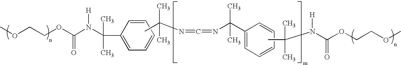
18. A polymer membrane comprising crosslinked poly(vinyl alcohol-co-vinylamine), wherein the polymer membrane further comprises a second polyamine and wherein the poly(vinyl alcohol-co-vinylamine) and the second polyamine are crosslinked with one another.
19. A method for preparing a polymer membrane according to claim 1 , said method comprising:
providing a membrane precursor composition comprising a poly(vinyl alcohol-co-vinylamine) and a crosslinking agent;
casting the membrane precursor composition in the form of a film; and
curing the film under conditions effective for the crosslinking agent to crosslink the poly(vinyl alcohol-co-vinylamine).
20-39. (canceled)
40. A method for preparing a polymer membrane according to claim 18 , said method comprising:
providing a membrane precursor composition comprising a poly(vinyl alcohol-co-vinylamine) and a crosslinking agent;
casting the membrane precursor composition in the form of a film; and
curing the film under conditions effective for the crosslinking agent to crosslink the poly(vinyl alcohol-co-vinylamine), wherein the membrane precursor composition further comprises a second polyamine and wherein the film is cured under conditions effective for the crosslinking agent to crosslink the poly(vinyl alcohol-co-vinylamine) and the second polyamine with one another.
41. A hybrid membrane structure comprising:
an inorganic porous support comprising a first end, a second end, and a plurality of inner channels having surfaces defined by porous walls and extending through the support from the first end to the second end;
optionally, one or more porous inorganic intermediate layers coating the inner channel surfaces of the inorganic porous support; and
a polymer membrane comprising crosslinked poly(vinyl alcohol-co-vinylamine); wherein, when the hybrid membrane structure does not comprise the one or more porous inorganic intermediate layers, the inner channel surfaces of the inorganic porous support comprise a median pore size of 500 nanometers or less and the polymer membrane coats the inner channel surfaces of the inorganic porous support; and wherein, when the hybrid membrane structure comprises the one or more porous inorganic intermediate layers, the polymer membrane coats the surface of the one or more porous intermediate layers.
42-54. (canceled)
55. A hybrid membrane structure comprising:
an inorganic porous support comprising a first end, a second end, and a plurality of inner channels having surfaces defined by porous walls and extending through the support from the first end to the second end;
optionally, one or more porous inorganic intermediate layers coating the inner channel surfaces of the inorganic porous support; and
a polymer membrane according to claim 1 ; wherein, when the hybrid membrane structure does not comprise the one or more porous inorganic intermediate layers, the polymer membrane coats the inner channel surfaces of the inorganic porous support and wherein, when the hybrid membrane structure comprises the one or more porous inorganic intermediate layers, the polymer membrane coats the surface of the one or more porous intermediate layers.
56. A hybrid membrane structure comprising:
an inorganic porous support comprising a first end, a second end, and a plurality of inner channels having surfaces defined by porous walls and extending through the support from the first end to the second end;
optionally, one or more porous inorganic intermediate layers coating the inner channel surfaces of the inorganic porous support; and
a polymer membrane according to claim 18 ; wherein, when the hybrid membrane structure does not comprise the one or more porous inorganic intermediate layers, the polymer membrane coats the inner channel surfaces of the inorganic porous support and wherein, when the hybrid membrane structure comprises the one or more porous inorganic intermediate layers, the polymer membrane coats the surface of the one or more porous intermediate layers.
57. A membrane precursor composition comprising:
a poly(vinyl alcohol-co-vinylamine);
a second polyamine; and
a crosslinking agent.
58-66. (canceled)
67. A method for making a hybrid membrane structure, said method comprising:
providing an inorganic porous support comprising a first end, a second end, and a plurality of inner channels having surfaces defined by porous walls and extending through the support from the first end to the second end;
optionally applying one or more porous inorganic intermediate layers to the inner channel surfaces of the inorganic porous support;
applying a membrane precursor composition comprising a poly(vinyl alcohol-co-vinylamine) and a crosslinking agent; wherein, when the one or more porous inorganic intermediate layers have not been applied to the inorganic porous support's inner channel surfaces, the inner channel surfaces of the inorganic porous support comprise a median pore size of 500 nanometers or less and the membrane precursor composition is applied to the inner channel surfaces of the inorganic porous support; and wherein, when the one or more porous inorganic intermediate layers have been applied to the inorganic porous support's inner channel surfaces, the membrane precursor composition is applied to the surface of the one or more porous intermediate layers; and
curing the membrane precursor composition under conditions effective for the crosslinking agent to crosslink the poly(vinyl alcohol-co-vinylamine).
68-74. (canceled)
75. A method for making a hybrid membrane structure, said method comprising:
providing an inorganic porous support comprising a first end, a second end, and a plurality of inner channels having surfaces defined by porous walls and extending through the support from the first end to the second end;
optionally applying one or more porous inorganic intermediate layers to the inner channel surfaces of the inorganic porous support;
applying a membrane precursor composition according to claim 57 ; wherein, when the one or more porous inorganic intermediate layers have not been applied to the inorganic porous support's inner channel surfaces, the membrane precursor coin position is applied to the inner channel surfaces of the inorganic porous support; and wherein, when the one or more porous inorganic intermediate layers have been applied to the inorganic porous support's inner channel surfaces, the membrane precursor composition is applied to the surface of the one or more porous intermediate layers; and
curing the membrane precursor composition under conditions effective for the crosslinking agent to crosslink the poly(vinyl alcohol-co-vinylamine) and the second polyamine with one another
76. A method for making a hybrid membrane structure, said method comprising:
providing an inorganic porous support comprising a first end, a second end, and a plurality of inner channels having surfaces defined by porous walls and extending through the support from the first end to the second end;
optionally applying one or more porous inorganic intermediate layers to the inner channel surfaces of the inorganic porous support;
applying a membrane precursor composition comprising a poly(vinyl alcohol-co-vinylamine) and a crosslinking agent; wherein, when the one or more porous inorganic intermediate layers have not been applied to the inorganic porous support's inner channel surfaces, the membrane precursor composition is applied to the inner channel surfaces of the inorganic porous support; and wherein, when the one or more porous inorganic intermediate layers have been applied to the inorganic porous support's inner channel surfaces, the membrane precursor composition is applied to the surface of the one or more porous intermediate layers; and
curing the membrane precursor composition under conditions effective for the crosslinking agent to crosslink the poly(vinyl alcohol-co-vinylamine) into a membrane which is non-porous or which is porous with pores having a median pore size of 300 nm or less.
Priority Applications (4)
| Application Number | Priority Date | Filing Date | Title |
|---|---|---|---|
| US12/112,535 US20090110907A1 (en) | 2007-10-29 | 2008-04-30 | Membranes Based On Poly (Vinyl Alcohol-Co-Vinylamine) |
| PCT/US2008/011988 WO2009058206A2 (en) | 2007-10-29 | 2008-10-21 | Membranes based on poly (vinyl alcohol-co-vinylamine) |
| JP2010532015A JP2011502750A (en) | 2007-10-29 | 2008-10-21 | Membrane based on poly (vinyl alcohol-co-vinylamine) |
| EP20080843638 EP2212010A2 (en) | 2007-10-29 | 2008-10-21 | Membranes based on poly (vinyl alcohol-co-vinylamine) |
Applications Claiming Priority (2)
| Application Number | Priority Date | Filing Date | Title |
|---|---|---|---|
| US81607P | 2007-10-29 | 2007-10-29 | |
| US12/112,535 US20090110907A1 (en) | 2007-10-29 | 2008-04-30 | Membranes Based On Poly (Vinyl Alcohol-Co-Vinylamine) |
Publications (1)
| Publication Number | Publication Date |
|---|---|
| US20090110907A1 true US20090110907A1 (en) | 2009-04-30 |
Family
ID=40583216
Family Applications (1)
| Application Number | Title | Priority Date | Filing Date |
|---|---|---|---|
| US12/112,535 Abandoned US20090110907A1 (en) | 2007-10-29 | 2008-04-30 | Membranes Based On Poly (Vinyl Alcohol-Co-Vinylamine) |
Country Status (4)
| Country | Link |
|---|---|
| US (1) | US20090110907A1 (en) |
| EP (1) | EP2212010A2 (en) |
| JP (1) | JP2011502750A (en) |
| WO (1) | WO2009058206A2 (en) |
Cited By (34)
| Publication number | Priority date | Publication date | Assignee | Title |
|---|---|---|---|---|
| US20090191626A1 (en) * | 2008-01-30 | 2009-07-30 | Christopher Bankole Shogbon | Synthetic Surfaces for Culturing Stem Cell Derived Oligodendrocyte Progenitor Cells |
| US20100248366A1 (en) * | 2008-01-30 | 2010-09-30 | Geron Corporation | Synthetic Surfaces for Differentiating Stem Cells into Cardiomyocytes |
| WO2010138489A1 (en) * | 2009-05-29 | 2010-12-02 | Corning Incorporated | Poly(amino-alcohol)-silica hybrid compositions and membranes |
| US20110183418A1 (en) * | 2009-07-29 | 2011-07-28 | Arthur Winston Martin | Peptide-Polymer Cell Culture Articles and Methods of Making |
| US20110277631A1 (en) * | 2009-11-12 | 2011-11-17 | National University Of Singapore | Method for modifying a polyimide membrane |
| US20120285881A1 (en) * | 2009-12-28 | 2012-11-15 | Yamaguchi University | Multilayered charge-mosaic membrane and manufacturing method therefor |
| CN103037955A (en) * | 2010-02-16 | 2013-04-10 | 公益财团法人地球环境产业技术研究机构 | Gas separation composite membrane |
| US8496732B2 (en) | 2010-11-12 | 2013-07-30 | The Texas A&M University System | Systems and methods for air dehumidification and sensible cooling using a multiple stage pump |
| US8563312B2 (en) | 2008-01-30 | 2013-10-22 | Geron Corporation | Synthetic surfaces for culturing stem cell derived cardiomyocytes |
| US20130287958A1 (en) * | 2011-01-12 | 2013-10-31 | Fujifilm Corporation | Method and apparatus of producing composite for carbon dioxide separation |
| US8685144B2 (en) | 2010-11-12 | 2014-04-01 | The Texas A&M University System | System and method for efficient air dehumidification and liquid recovery |
| US8685145B2 (en) | 2010-11-12 | 2014-04-01 | The Texas A&M University System | System and method for efficient multi-stage air dehumidification and liquid recovery |
| US8685142B2 (en) | 2010-11-12 | 2014-04-01 | The Texas A&M University System | System and method for efficient air dehumidification and liquid recovery with evaporative cooling |
| JP2014113522A (en) * | 2012-12-06 | 2014-06-26 | Molecular Gate Membrane Module Technology Research Association | Gas separation membrane |
| US20140194564A1 (en) * | 2011-06-23 | 2014-07-10 | Rosa Carceller | Polymer product and the use of the same as dispersing agent |
| US20140241966A1 (en) * | 2012-10-25 | 2014-08-28 | Georgia Tech Research Corporation | Supported poly(allyl)amine and derivatives for co2 capture from flue gas or ultra-dilute gas streams such as ambient air or admixtures thereof |
| US20140283685A1 (en) * | 2009-02-02 | 2014-09-25 | Norwegian University Of Science And Technology | Gas separation membrane |
| US8956696B2 (en) | 2011-02-10 | 2015-02-17 | Inficon Gmbh | Ultra-thin membrane for chemical analyzer and related method for forming membrane |
| US9162178B2 (en) | 2011-01-12 | 2015-10-20 | Fujifilm Corporation | Composition for formation of carbon dioxide separation membrane, carbon dioxide separation membrane and process for production thereof, and carbon dioxide separation apparatus |
| EP2998329A3 (en) * | 2010-02-24 | 2016-04-06 | Relypsa, Inc. | Crosslinked polyvinylamine, polyallylamine, and polyethyleneimine for use as bile acid sequestrants |
| WO2016113761A1 (en) | 2015-01-15 | 2016-07-21 | Council Of Scientific & Industrial Research | Hydrophobic polymer-supported lewis acid catalyst and process for the preparation thereof |
| US9427726B2 (en) | 2011-10-13 | 2016-08-30 | Georgia Tech Research Corporation | Vapor phase methods of forming supported highly branched polyamines |
| US9433896B2 (en) | 2010-04-30 | 2016-09-06 | Peter Eisenberger | System and method for carbon dioxide capture and sequestration |
| US9555365B2 (en) | 2007-05-21 | 2017-01-31 | Peter Eisenberger | System and method for removing carbon dioxide from an atmosphere and global thermostat using the same |
| WO2017078219A1 (en) * | 2015-11-05 | 2017-05-11 | 한국과학기술원 | Polyethyleneimine modified by partial substitution with hydroxyethyl group, and method for producing same |
| US20170203254A1 (en) * | 2014-11-05 | 2017-07-20 | Ngk Insulators, Ltd. | Package, method for storing or transporting sub-nano membrane structure, and sub-nano membrane structure |
| US9908080B2 (en) | 2007-05-21 | 2018-03-06 | Peter Eisenberger | System and method for removing carbon dioxide from an atmosphere and global thermostat using the same |
| US9925488B2 (en) | 2010-04-30 | 2018-03-27 | Peter Eisenberger | Rotating multi-monolith bed movement system for removing CO2 from the atmosphere |
| US9975087B2 (en) | 2010-04-30 | 2018-05-22 | Peter Eisenberger | System and method for carbon dioxide capture and sequestration from relatively high concentration CO2 mixtures |
| CN108905625A (en) * | 2018-07-20 | 2018-11-30 | 安徽原上草节能环保科技有限公司 | A kind of reverse osmosis membrane and its preparation method and application |
| WO2020206148A1 (en) * | 2019-04-03 | 2020-10-08 | Arizona Board Of Regents On Behalf Of Arizona State University | System and method for carbon dioxide capture through membrane conduits |
| CN112657346A (en) * | 2020-12-16 | 2021-04-16 | 杭州科百特科技有限公司 | RC ultrafiltration membrane and preparation method thereof |
| CN116116170A (en) * | 2021-11-15 | 2023-05-16 | 中石化南京化工研究院有限公司 | Alcohol amine-containing composition with acid gas absorption function and application thereof |
| US12285729B1 (en) * | 2024-05-08 | 2025-04-29 | Imam Mohammad Ibn Saud Islamic University | Glass supported separation membrane |
Families Citing this family (7)
| Publication number | Priority date | Publication date | Assignee | Title |
|---|---|---|---|---|
| JP5563503B2 (en) * | 2011-03-15 | 2014-07-30 | 公益財団法人地球環境産業技術研究機構 | Gas separation composite membrane |
| WO2013136869A1 (en) * | 2012-03-16 | 2013-09-19 | 日本碍子株式会社 | Process for producing separation membrane, process for producing separation membrane composite, and separation membrane composite |
| JP6231927B2 (en) * | 2014-03-28 | 2017-11-15 | 次世代型膜モジュール技術研究組合 | Gas separation membrane |
| JP6231928B2 (en) * | 2014-03-28 | 2017-11-15 | 次世代型膜モジュール技術研究組合 | Gas separation membrane |
| FR3024665B1 (en) * | 2014-08-11 | 2020-05-08 | Technologies Avancees Et Membranes Industrielles | TANGENTIAL FLOW SEPARATION ELEMENT INCLUDING TRAFFIC OBSTACLES AND MANUFACTURING METHOD |
| KR101967508B1 (en) * | 2016-07-08 | 2019-04-09 | 한국과학기술원 | Polymeric amine based adsorbent for carbon dioxide capture |
| WO2025258080A1 (en) * | 2024-06-14 | 2025-12-18 | 国立大学法人京都工芸繊維大学 | Amine-containing polymer membrane, production method therefor, and method for separating carbon dioxide |
Citations (16)
| Publication number | Priority date | Publication date | Assignee | Title |
|---|---|---|---|---|
| US5595821A (en) * | 1994-05-04 | 1997-01-21 | Minnesota Mining And Manufacturing Company | Repulpable plastic films |
| US5611843A (en) * | 1995-07-07 | 1997-03-18 | Exxon Research And Engineering Company | Membranes comprising salts of aminoacids in hydrophilic polymers |
| US6099621A (en) * | 1997-03-14 | 2000-08-08 | Exxon Research And Engineering Company | Membranes comprising aminoacid salts in polyamine polymers and blends |
| US6315968B1 (en) * | 1995-01-18 | 2001-11-13 | Air Products And Chemicals, Inc. | Process for separating acid gases from gaseous mixtures utilizing composite membranes formed from salt-polymer blends |
| US20040047799A1 (en) * | 2002-09-06 | 2004-03-11 | H2Fuel, Llc | Dynamic sulfur tolerant process and system with inline acid gas-selective removal for generating hydrogen for fuel cells |
| US20040118747A1 (en) * | 2002-12-18 | 2004-06-24 | Cutler Willard A. | Structured adsorbents for desulfurizing fuels |
| US20040211319A1 (en) * | 2003-04-11 | 2004-10-28 | Yong Soo Kang | Facilitated transport membranes comprising a porous support and a solid polymer electrolyte consisting of a transition metal salt and a polymer having phthalic structure |
| US20050077226A1 (en) * | 2003-10-14 | 2005-04-14 | Bishop Bruce A. | Membrane devices using reaction bonded monolith supports |
| US20050092683A1 (en) * | 2003-10-31 | 2005-05-05 | Goldsmith Robert L. | Membrane devices for pervaporation, gas separations, and perstraction with permeate and sweep fluid conduit and method of use |
| US20050191426A1 (en) * | 2004-02-05 | 2005-09-01 | Wilson Moya | Method of forming coated structures |
| US20050211624A1 (en) * | 2004-03-23 | 2005-09-29 | Vane Leland M | Hydrophilic cross-linked polymeric membranes and sorbents |
| US7011694B1 (en) * | 2001-05-14 | 2006-03-14 | University Of Kentucky Research Foundation | CO2-selective membranes containing amino groups |
| US20060183632A1 (en) * | 2005-02-14 | 2006-08-17 | Shustack Paul J | Coated ceramic catalyst supports and method |
| US7132150B2 (en) * | 2003-08-14 | 2006-11-07 | Corning Incorporated | Porous ceramic filters with catalyst coatings |
| US20080078290A1 (en) * | 2006-09-11 | 2008-04-03 | Hagg May-Britt | Membrane |
| US20090110873A1 (en) * | 2007-10-29 | 2009-04-30 | Jiang Dayue D | Polymer Hybrid Membrane Structures |
Family Cites Families (9)
| Publication number | Priority date | Publication date | Assignee | Title |
|---|---|---|---|---|
| JPS61101203A (en) * | 1984-10-24 | 1986-05-20 | Toray Ind Inc | Highly permeable composite membrane |
| JPH01254227A (en) * | 1988-03-31 | 1989-10-11 | Kuraray Co Ltd | Steam permselective membrane |
| EP0674937A3 (en) * | 1994-03-30 | 1995-11-22 | Corning Inc | Non-porous polymeric membrane on a porous inorganic support. |
| EP0772488B1 (en) * | 1994-07-28 | 2001-01-31 | Millipore Corporation | Porous composite membrane and process |
| JPH11538A (en) * | 1997-06-09 | 1999-01-06 | Kureha Chem Ind Co Ltd | Selectively gas permeable film and its production |
| US20020127474A1 (en) * | 2001-01-09 | 2002-09-12 | E.C.R.-Electro-Chemical Research Ltd. | Proton-selective conducting membranes |
| NO322564B1 (en) * | 2004-03-22 | 2006-10-23 | Ntnu Technology Transfer As | Composite membrane, process for its preparation, and its use for separating CO2 from gas mixtures. |
| US20050266229A1 (en) * | 2004-05-26 | 2005-12-01 | Richard Porticos | Nonwoven with attached foam particles |
| JP2006130453A (en) * | 2004-11-08 | 2006-05-25 | Niigata Univ | Liquid membrane for gas / vapor separation and manufacturing method thereof, gas / vapor membrane separation device |
-
2008
- 2008-04-30 US US12/112,535 patent/US20090110907A1/en not_active Abandoned
- 2008-10-21 EP EP20080843638 patent/EP2212010A2/en not_active Withdrawn
- 2008-10-21 JP JP2010532015A patent/JP2011502750A/en active Pending
- 2008-10-21 WO PCT/US2008/011988 patent/WO2009058206A2/en not_active Ceased
Patent Citations (17)
| Publication number | Priority date | Publication date | Assignee | Title |
|---|---|---|---|---|
| US5595821A (en) * | 1994-05-04 | 1997-01-21 | Minnesota Mining And Manufacturing Company | Repulpable plastic films |
| US6315968B1 (en) * | 1995-01-18 | 2001-11-13 | Air Products And Chemicals, Inc. | Process for separating acid gases from gaseous mixtures utilizing composite membranes formed from salt-polymer blends |
| US5611843A (en) * | 1995-07-07 | 1997-03-18 | Exxon Research And Engineering Company | Membranes comprising salts of aminoacids in hydrophilic polymers |
| US6099621A (en) * | 1997-03-14 | 2000-08-08 | Exxon Research And Engineering Company | Membranes comprising aminoacid salts in polyamine polymers and blends |
| US7011694B1 (en) * | 2001-05-14 | 2006-03-14 | University Of Kentucky Research Foundation | CO2-selective membranes containing amino groups |
| US20040047799A1 (en) * | 2002-09-06 | 2004-03-11 | H2Fuel, Llc | Dynamic sulfur tolerant process and system with inline acid gas-selective removal for generating hydrogen for fuel cells |
| US20040118747A1 (en) * | 2002-12-18 | 2004-06-24 | Cutler Willard A. | Structured adsorbents for desulfurizing fuels |
| US20040211319A1 (en) * | 2003-04-11 | 2004-10-28 | Yong Soo Kang | Facilitated transport membranes comprising a porous support and a solid polymer electrolyte consisting of a transition metal salt and a polymer having phthalic structure |
| US7132150B2 (en) * | 2003-08-14 | 2006-11-07 | Corning Incorporated | Porous ceramic filters with catalyst coatings |
| US20050077226A1 (en) * | 2003-10-14 | 2005-04-14 | Bishop Bruce A. | Membrane devices using reaction bonded monolith supports |
| US20050092683A1 (en) * | 2003-10-31 | 2005-05-05 | Goldsmith Robert L. | Membrane devices for pervaporation, gas separations, and perstraction with permeate and sweep fluid conduit and method of use |
| US20050191426A1 (en) * | 2004-02-05 | 2005-09-01 | Wilson Moya | Method of forming coated structures |
| US20050211624A1 (en) * | 2004-03-23 | 2005-09-29 | Vane Leland M | Hydrophilic cross-linked polymeric membranes and sorbents |
| US20070051680A1 (en) * | 2004-03-23 | 2007-03-08 | Leland Vane | Hydrophilic cross-linked polymeric membranes and sorbents |
| US20060183632A1 (en) * | 2005-02-14 | 2006-08-17 | Shustack Paul J | Coated ceramic catalyst supports and method |
| US20080078290A1 (en) * | 2006-09-11 | 2008-04-03 | Hagg May-Britt | Membrane |
| US20090110873A1 (en) * | 2007-10-29 | 2009-04-30 | Jiang Dayue D | Polymer Hybrid Membrane Structures |
Cited By (55)
| Publication number | Priority date | Publication date | Assignee | Title |
|---|---|---|---|---|
| US9908080B2 (en) | 2007-05-21 | 2018-03-06 | Peter Eisenberger | System and method for removing carbon dioxide from an atmosphere and global thermostat using the same |
| US9555365B2 (en) | 2007-05-21 | 2017-01-31 | Peter Eisenberger | System and method for removing carbon dioxide from an atmosphere and global thermostat using the same |
| US9745550B2 (en) | 2008-01-30 | 2017-08-29 | Asterias Biotherapeutics, Inc. | Synthetic surfaces for culturing stem cell derived cardiomyocytes |
| US10221390B2 (en) | 2008-01-30 | 2019-03-05 | Asterias Biotherapeutics, Inc. | Synthetic surfaces for culturing stem cell derived oligodendrocyte progenitor cells |
| US20100248366A1 (en) * | 2008-01-30 | 2010-09-30 | Geron Corporation | Synthetic Surfaces for Differentiating Stem Cells into Cardiomyocytes |
| US20090191626A1 (en) * | 2008-01-30 | 2009-07-30 | Christopher Bankole Shogbon | Synthetic Surfaces for Culturing Stem Cell Derived Oligodendrocyte Progenitor Cells |
| US8563312B2 (en) | 2008-01-30 | 2013-10-22 | Geron Corporation | Synthetic surfaces for culturing stem cell derived cardiomyocytes |
| US8513009B2 (en) | 2008-01-30 | 2013-08-20 | Geron Corporation | Synthetic surfaces for culturing stem cell derived oligodendrocyte progenitor cells |
| US20140283685A1 (en) * | 2009-02-02 | 2014-09-25 | Norwegian University Of Science And Technology | Gas separation membrane |
| US9623380B2 (en) * | 2009-02-02 | 2017-04-18 | Norwegian University Of Science And Technology | Gas separation membrane |
| WO2010138489A1 (en) * | 2009-05-29 | 2010-12-02 | Corning Incorporated | Poly(amino-alcohol)-silica hybrid compositions and membranes |
| US8052776B2 (en) * | 2009-05-29 | 2011-11-08 | Corning Incorporated | Poly(amino-alcohol)-silica hybrid compositions and membranes |
| US20100300289A1 (en) * | 2009-05-29 | 2010-12-02 | Jiang Dayue D | Poly(amino-alcohol)-silica hybrid compositions and membranes |
| US20110183418A1 (en) * | 2009-07-29 | 2011-07-28 | Arthur Winston Martin | Peptide-Polymer Cell Culture Articles and Methods of Making |
| US20110277631A1 (en) * | 2009-11-12 | 2011-11-17 | National University Of Singapore | Method for modifying a polyimide membrane |
| US20120285881A1 (en) * | 2009-12-28 | 2012-11-15 | Yamaguchi University | Multilayered charge-mosaic membrane and manufacturing method therefor |
| US9346020B2 (en) * | 2009-12-28 | 2016-05-24 | Kuraray Co., Ltd. | Multilayered charge-mosaic membrane and manufacturing method therefor |
| CN103037955A (en) * | 2010-02-16 | 2013-04-10 | 公益财团法人地球环境产业技术研究机构 | Gas separation composite membrane |
| US10272103B2 (en) | 2010-02-24 | 2019-04-30 | Relypsa, Inc. | Crosslinked polyvinylamine, polyallylamine, and polyethyleneimine for use as bile acid sequestrants |
| EP2998329A3 (en) * | 2010-02-24 | 2016-04-06 | Relypsa, Inc. | Crosslinked polyvinylamine, polyallylamine, and polyethyleneimine for use as bile acid sequestrants |
| US9878286B2 (en) | 2010-04-30 | 2018-01-30 | Peter Eisenberger | System and method for carbon dioxide capture and sequestration |
| US9433896B2 (en) | 2010-04-30 | 2016-09-06 | Peter Eisenberger | System and method for carbon dioxide capture and sequestration |
| US10512880B2 (en) | 2010-04-30 | 2019-12-24 | Peter Eisenberger | Rotating multi-monolith bed movement system for removing CO2 from the atmosphere |
| US10413866B2 (en) | 2010-04-30 | 2019-09-17 | Peter Eisenberger | System and method for carbon dioxide capture and sequestration |
| US9975087B2 (en) | 2010-04-30 | 2018-05-22 | Peter Eisenberger | System and method for carbon dioxide capture and sequestration from relatively high concentration CO2 mixtures |
| US9925488B2 (en) | 2010-04-30 | 2018-03-27 | Peter Eisenberger | Rotating multi-monolith bed movement system for removing CO2 from the atmosphere |
| US9630143B2 (en) | 2010-04-30 | 2017-04-25 | Peter Eisenberger | System and method for carbon dioxide capture and sequestration utilizing an improved substrate structure |
| US8685144B2 (en) | 2010-11-12 | 2014-04-01 | The Texas A&M University System | System and method for efficient air dehumidification and liquid recovery |
| US8641806B2 (en) | 2010-11-12 | 2014-02-04 | The Texas A&M University System | Systems and methods for multi-stage air dehumidification and cooling |
| US8496732B2 (en) | 2010-11-12 | 2013-07-30 | The Texas A&M University System | Systems and methods for air dehumidification and sensible cooling using a multiple stage pump |
| US8500848B2 (en) | 2010-11-12 | 2013-08-06 | The Texas A&M University System | Systems and methods for air dehumidification and cooling with membrane water vapor rejection |
| US8685142B2 (en) | 2010-11-12 | 2014-04-01 | The Texas A&M University System | System and method for efficient air dehumidification and liquid recovery with evaporative cooling |
| US8685145B2 (en) | 2010-11-12 | 2014-04-01 | The Texas A&M University System | System and method for efficient multi-stage air dehumidification and liquid recovery |
| US8916238B2 (en) * | 2011-01-12 | 2014-12-23 | Fujifilm Corporation | Method and apparatus of producing composite for carbon dioxide separation |
| US20130287958A1 (en) * | 2011-01-12 | 2013-10-31 | Fujifilm Corporation | Method and apparatus of producing composite for carbon dioxide separation |
| US9162178B2 (en) | 2011-01-12 | 2015-10-20 | Fujifilm Corporation | Composition for formation of carbon dioxide separation membrane, carbon dioxide separation membrane and process for production thereof, and carbon dioxide separation apparatus |
| US8956696B2 (en) | 2011-02-10 | 2015-02-17 | Inficon Gmbh | Ultra-thin membrane for chemical analyzer and related method for forming membrane |
| US9034977B2 (en) * | 2011-06-23 | 2015-05-19 | Kemira Oyj | Polymer product and the use of the same as dispersing agent |
| US20140194564A1 (en) * | 2011-06-23 | 2014-07-10 | Rosa Carceller | Polymer product and the use of the same as dispersing agent |
| US9427726B2 (en) | 2011-10-13 | 2016-08-30 | Georgia Tech Research Corporation | Vapor phase methods of forming supported highly branched polyamines |
| US20140241966A1 (en) * | 2012-10-25 | 2014-08-28 | Georgia Tech Research Corporation | Supported poly(allyl)amine and derivatives for co2 capture from flue gas or ultra-dilute gas streams such as ambient air or admixtures thereof |
| US11059024B2 (en) * | 2012-10-25 | 2021-07-13 | Georgia Tech Research Corporation | Supported poly(allyl)amine and derivatives for CO2 capture from flue gas or ultra-dilute gas streams such as ambient air or admixtures thereof |
| JP2014113522A (en) * | 2012-12-06 | 2014-06-26 | Molecular Gate Membrane Module Technology Research Association | Gas separation membrane |
| CN107074427A (en) * | 2014-11-05 | 2017-08-18 | 日本碍子株式会社 | Package body, the keeping of sub- nanofilmstructures body or carrying method and sub- nanofilmstructures body |
| US10618011B2 (en) * | 2014-11-05 | 2020-04-14 | Ngk Insulators, Ltd. | Package, method for storing or transporting sub-nano membrane structure, and sub-nano membrane structure |
| US20170203254A1 (en) * | 2014-11-05 | 2017-07-20 | Ngk Insulators, Ltd. | Package, method for storing or transporting sub-nano membrane structure, and sub-nano membrane structure |
| WO2016113761A1 (en) | 2015-01-15 | 2016-07-21 | Council Of Scientific & Industrial Research | Hydrophobic polymer-supported lewis acid catalyst and process for the preparation thereof |
| WO2017078219A1 (en) * | 2015-11-05 | 2017-05-11 | 한국과학기술원 | Polyethyleneimine modified by partial substitution with hydroxyethyl group, and method for producing same |
| CN108905625A (en) * | 2018-07-20 | 2018-11-30 | 安徽原上草节能环保科技有限公司 | A kind of reverse osmosis membrane and its preparation method and application |
| WO2020206148A1 (en) * | 2019-04-03 | 2020-10-08 | Arizona Board Of Regents On Behalf Of Arizona State University | System and method for carbon dioxide capture through membrane conduits |
| US20220203292A1 (en) * | 2019-04-03 | 2022-06-30 | Klaus Lackner | System and method for carbon dioxide capture through membrane conduits |
| US12121849B2 (en) * | 2019-04-03 | 2024-10-22 | Arizona Board Of Regents On Behalf Of Arizona State University | System and method for carbon dioxide capture through membrane conduits |
| CN112657346A (en) * | 2020-12-16 | 2021-04-16 | 杭州科百特科技有限公司 | RC ultrafiltration membrane and preparation method thereof |
| CN116116170A (en) * | 2021-11-15 | 2023-05-16 | 中石化南京化工研究院有限公司 | Alcohol amine-containing composition with acid gas absorption function and application thereof |
| US12285729B1 (en) * | 2024-05-08 | 2025-04-29 | Imam Mohammad Ibn Saud Islamic University | Glass supported separation membrane |
Also Published As
| Publication number | Publication date |
|---|---|
| WO2009058206A2 (en) | 2009-05-07 |
| JP2011502750A (en) | 2011-01-27 |
| WO2009058206A3 (en) | 2010-05-27 |
| EP2212010A2 (en) | 2010-08-04 |
Similar Documents
| Publication | Publication Date | Title |
|---|---|---|
| US20090110907A1 (en) | Membranes Based On Poly (Vinyl Alcohol-Co-Vinylamine) | |
| US7914875B2 (en) | Polymer hybrid membrane structures | |
| US9457323B2 (en) | Carbon dioxide separation member, method for producing same, and carbon dioxide separation module | |
| CN101679135B (en) | Method for preparing a porous inorganic coating on a porous support using certain pore fillers | |
| KR102236713B1 (en) | Composite semipermeable membrane and method for manufacturing same | |
| US20090107330A1 (en) | Amorphous silica hybrid membrane structure | |
| US8481110B2 (en) | Methods of making inorganic membranes | |
| JP6197649B2 (en) | Composite semipermeable membrane | |
| CA2935535A1 (en) | Composite membranes and methods of use | |
| US20130012633A1 (en) | Hybrid composition and membrane based on silylated hydrophilic polymer | |
| CN112368066B (en) | Carbon dioxide separation membrane with amino group-containing graft polymer surface | |
| WO2011136865A1 (en) | Polyamide membrane with a coating comprising polyalkylene oxide and triazine compounds | |
| JP5840574B2 (en) | Method for producing composite for carbon dioxide separation, composite for carbon dioxide separation, and module for carbon dioxide separation | |
| WO2021219692A1 (en) | Thin-film composite membranes synthesized by multi-step coating methods | |
| CN113226527A (en) | Composite semipermeable membrane | |
| JP5946220B2 (en) | Complex for acid gas separation, module for acid gas separation, and method for producing module for acid gas separation | |
| KR20160071855A (en) | Method for manufacturing water treatment separating membrane and water treatment separating membrane manufactured by the same | |
| EP3424596A1 (en) | Method for coating a monolith carrier | |
| WO2018220209A1 (en) | Ultra-stable poly(epoxy)ether thin-film composite membranes made via interfacial initiation | |
| JP2023104369A (en) | Gas separation membrane, gas separation membrane module, method for producing the same, and method for gas separation using the same | |
| JP2025000341A (en) | Carbon dioxide separation membrane, manufacturing method of carbon dioxide separation membrane, carbon dioxide separation method, and carbon dioxide separation membrane module | |
| JP2011083729A (en) | Composite separation membrane and method for manufacturing the same | |
| CN120916831A (en) | Separation membrane | |
| JP2011083728A (en) | Composite separation membrane and method for manufacturing the same |
Legal Events
| Date | Code | Title | Description |
|---|---|---|---|
| AS | Assignment |
Owner name: CORNING INCORPORATED, NEW YORK Free format text: ASSIGNMENT OF ASSIGNORS INTEREST;ASSIGNORS:JIANG, DAYUE D;LIU, WEI;SHUSTACK, PAUL JOHN;AND OTHERS;REEL/FRAME:020880/0371;SIGNING DATES FROM 20080423 TO 20080429 |
|
| STCB | Information on status: application discontinuation |
Free format text: ABANDONED -- AFTER EXAMINER'S ANSWER OR BOARD OF APPEALS DECISION |