US20030086788A1 - Three dimensional blade - Google Patents
Three dimensional blade Download PDFInfo
- Publication number
- US20030086788A1 US20030086788A1 US10/176,077 US17607702A US2003086788A1 US 20030086788 A1 US20030086788 A1 US 20030086788A1 US 17607702 A US17607702 A US 17607702A US 2003086788 A1 US2003086788 A1 US 2003086788A1
- Authority
- US
- United States
- Prior art keywords
- blade
- improved
- steam turbine
- axial steam
- dimensional
- Prior art date
- Legal status (The legal status is an assumption and is not a legal conclusion. Google has not performed a legal analysis and makes no representation as to the accuracy of the status listed.)
- Granted
Links
Images


Classifications
-
- F—MECHANICAL ENGINEERING; LIGHTING; HEATING; WEAPONS; BLASTING
- F01—MACHINES OR ENGINES IN GENERAL; ENGINE PLANTS IN GENERAL; STEAM ENGINES
- F01D—NON-POSITIVE DISPLACEMENT MACHINES OR ENGINES, e.g. STEAM TURBINES
- F01D5/00—Blades; Blade-carrying members; Heating, heat-insulating, cooling or antivibration means on the blades or the members
- F01D5/12—Blades
- F01D5/14—Form or construction
- F01D5/141—Shape, i.e. outer, aerodynamic form
-
- Y—GENERAL TAGGING OF NEW TECHNOLOGICAL DEVELOPMENTS; GENERAL TAGGING OF CROSS-SECTIONAL TECHNOLOGIES SPANNING OVER SEVERAL SECTIONS OF THE IPC; TECHNICAL SUBJECTS COVERED BY FORMER USPC CROSS-REFERENCE ART COLLECTIONS [XRACs] AND DIGESTS
- Y10—TECHNICAL SUBJECTS COVERED BY FORMER USPC
- Y10S—TECHNICAL SUBJECTS COVERED BY FORMER USPC CROSS-REFERENCE ART COLLECTIONS [XRACs] AND DIGESTS
- Y10S416/00—Fluid reaction surfaces, i.e. impellers
- Y10S416/02—Formulas of curves
Definitions
- the invention relates to an improved three dimensional blade for axial steam turbine particularly to the aerodynamic improvement of moving blades pertaining to entry stages of axial steam turbine.
- a conventional blade known as cylindrical blade is cylindrical in shape and made of a constant cross-section throughout the blade height.
- the invention primarily relates to moving blade of axial steam turbines, but the principle and design procedure are applicable for also to fixed blades, known as guide or stationary blades.
- the term ‘turbine blade’ is used in the description to denote aerofoil blades.
- the efficiency of turbine is of paramount importance for cheaper power generation.
- the blades are supposed to be most crucial apart from stationary flow path components for efficiency of the turbine.
- the conventional blades is of constant cross section and cylindrical in shape over the blade height.
- the U.S. Pat. No. 5,779,443 which was granted in 1998 is one such belonging to prior art in this area. At any cross section the shape of the profile remains same.
- the main object of the present invention is to propose an improved blade to reduce the losses by leaning and twisting the blade profiles so as to have aft-loaded blade instead of centrally loaded one at sections near root and tip.
- an improved three dimensional blade for axial steam turbine comprising a leading edge for inlet flow and a trailing edge for an angle, a pressure face, suction face and a chord which is the line connecting the leading and trailing edge and the betabi, the stagger angle formed at the intersection of said chord and U-axis wherein the blade is made of varying cross-sections of profiles hub to tip and leaned such that the centre of gravity of mid sections are shifted opposite to the direction of blade rotation and the blade sections from hub to tip are twisted in a gradual manner.
- FIG. 1 shows the profile geometry definition of the blade of this invention.
- FIG. 2 shows the stacked profiles hub to tip of the blade of the invention.
- FIG. 3 shows the blade of the invention with profile description Bezier Knots.
- FIG. 4A shows the base profile and Bezier knots for root profiles of the blade of the invention.
- FIG. 4B shows the base profile Bezier knots for mean profile.
- FIG. 5A shows the base profile and Bezier Knots for tip profile of the blade of the invention.
- FIG. 5B shows the base profile & Bezier Knots for a typical cylindrical blade.
- FIG. 6A shows the surface pressure distributions for profiles of 3ds1_r1 midheight blades.
- FIG. 6B shows the surface pressure distribution for profiles of 3ds1_r6, mid height blades.
- FIG. 6 c shows the surface pressure distribution for profiles of 3ds1_r11 mid height blades.
- FIG. 6D shows the surface pressure distribution of cy1 blade mid height.
- FIG. 7A shows Iso-Pressure Contour plots of a 3ds1_r1 blade.
- FIG. 7B shows Iso-Pressure Contour plots of a 3ds1_r6 blade.
- FIG. 8A shows Iso-Pressure Contour plots of a 3ds1_r11 blade.
- FIG. 8B shows Iso-Pressure Contour plots of a cy1 blade.
- FIG. 9A shows for 3ds1_r blade the stagger angle variation over the blade height.
- FIG. 9B same as FIG. 9A showing leaning of blade profile section.
- FIG. 10 shows various curves and CAD view of 3ds1_r blade.
- FIG. 11 shows Iso-metric view of various curves of a 3ds1_r blade.
- FIG. 12 shows surface pressure distribution of a 3ds1_r blade.
- FIG. 13 shows the surface pressure distribution of cylindrical blade.
- the present invention relates to the aerodynamic improvement of moving blades pertaining to entry stages of axial steam turbines.
- the invented blade is made of varying cross-sections and leaned such that the centres of gravity of these sections lie in a curve instead of a straight line. Centres of gravity of mid sections are shifted to the direction opposite of blade rotation compared to those of end sections. In addition to it the blade section from hub to tip are twisted in gradual manner unlike single setting angle in case of cylindrical blades. The purpose of the setting and leaning was reduction of pressure loading at end walls. This has resulted in significant improvement in aerodynamic efficiency.
- the profile or section is made of two surfaces: (FIG. 1) suction face ( 22 ) and pressure face ( 25 ), each joining leading edge ( 23 ) to trailing edge ( 28 ), X-axis ( 29 ) and U-axis ( 30 ) concide to turbine axis and circumferential direction respectively.
- the centre of gravity lies at origin of co-ordinate axies ( 31 ).
- the blade or profile is set at angle ‘betabi’ ( 26 ) or ⁇ , tg, is also known as stagger angle ( 26 ) with respet to U-axis ( 30 ).
- Chord ( 20 ) is defined as profile length joining leading edge (le) ( 23 ) to traiing edge (te) ( 28 ).
- Axial chord ( 21 ) is the projected length of the profile on X-axis ( 29 ).
- Inlet ( 24 ) and exit flow ( 27 ) angles ⁇ 1, tg and ⁇ 2, tg are fluid flow angles ( 24 , 27 ) with respect to tangent (U-axis) ( 30 ) respectively.
- the profile faces can be specified by various ways; e.g.; through discrete points (x,y co-ordinates), through a set of arcs and through bezier points ( 1 - 15 ) FIG. 3.
- the proposed blade is made of many such profiles (FIG. 1) but with varying shape and other parameters such as stagger angle ( 26 ) chord ( 20 ) axial chord ( 21 ), cross sectional areas.
- the centres of gravity (xcg, ycg) of the profiles do not coincide in x-y planes.
- a typical sketch of such set of stacked profiles for alternate 5 sections of total 11 sections are shown in FIG. 2.
- FIG. 5 also provides a schematic view of cylindrical blade profile and associated bezier knots.
- 3ds1_r family are stacked with specified stagger and interpolated parabolically (Lagrangian type) to 11 equidistant sections such that 1, 6 and 11 sections coincide to original root, mean and tip profiles: 3ds1_r1 3ds1_r6; 3ds1_r11; respectively (FIG. 2).
- po 1 and po 2 are mass averaged stagnation pressure at the inlet and exit of the cascade.
- Each of the blade is made of single profile for desired aspect ratio h/c, h and c are the blade height and chord, respectively.
- the blades are set at some stagger angle ⁇ , tg ( 26 ) with usually optimum pitch-cord ratio s/c (s is the pitch).
- the stagger angle ( 26 ) is acute angle between profile chord ( 20 ) and circumferential direction ( 30 ).
- 3D-Blade Design 3ds1_r blade is formed by stacking 3 basic profile with Lagrangian parabolic distribution and leaning them as per Design Curve (FIG. 9).
- h/c blade height/chord at hub
- the stagger angle variation is from +10.5 ⁇ 1 to ⁇ 12.2 ⁇ 1 degrees with respect to mean section.
- Section leaning profile shifting in negative U-direction for such a blade is shown in FIG. 9.
- Such a 3ds1_r blade with hub and tip areas 374 , and 194.7 mm 2 , of height 63.4 mm will have a mass of 0.137 Kg and cause centrifugal stress at root (of root radius 425 mm, 3000 rpm machine and 7740 Kg/m 3 material density) 16.34 N/mm 2 .
- the 3ds1_r blade is designed by inhouse software ‘quick3ds1’ which needs as basic inputs 2 or more input bezier profiles (data set profiles in term of bezier knots) (usually 3 profiles); their stagger angles and radial locations (r coordinate) along the blade height and—y-shift of centre of gravity (see FIG. 9) for leaning.
- the isometric views of 3ds1_r blade are shown in FIG. 10- 11 .
- Original blade of a given height (63.4 mm) can be reduced in height from tip side or extrapolated toward tip side.
- blade height varies from 40 to 75 mm which root axial chord 40 mm.
- the aspect ratio variation found useful for loss reduction is 0.85 to 1.5.
- 3D-CFD Analysis Three dimensional flow analysis by a CFD solver was carried out for a typical flow condition resembling high pressure power turbine first stage; for both cylindrical blade ‘Cy1’ and 3ds1_r blade. Surface pressure distribution with respect to axial direction, say z, and aerodynamic efficiency are computed.
- the 3ds1_r blade appears to be aft-loaded showing large pressure differences between pressure and suction surface at minimum pressure points.
- the typical distribution is inclined trapezoid in shape; viz, the shape of pressure variation in the first part of suction face is somewhat parallel to that of second part of pressure face.
- the pressure minima is toward the trailing edge side (FIG. 12).
- the cylindrical blade is centrally loaded with pressure minima midway (axial chord).
- the pressure distribution shape appears to that of a covered cup type (FIG. 13).
- Efficiency is defined here by 2 ways, each one based on mass-averaged conditions at cascade station upstream (1) and downstream (2):
Landscapes
- Engineering & Computer Science (AREA)
- Physics & Mathematics (AREA)
- Fluid Mechanics (AREA)
- Mechanical Engineering (AREA)
- General Engineering & Computer Science (AREA)
- Turbine Rotor Nozzle Sealing (AREA)
Abstract
Description
- The invention relates to an improved three dimensional blade for axial steam turbine particularly to the aerodynamic improvement of moving blades pertaining to entry stages of axial steam turbine.
- A conventional blade known as cylindrical blade, is cylindrical in shape and made of a constant cross-section throughout the blade height.
- The invention primarily relates to moving blade of axial steam turbines, but the principle and design procedure are applicable for also to fixed blades, known as guide or stationary blades. The term ‘turbine blade’ is used in the description to denote aerofoil blades. The efficiency of turbine is of paramount importance for cheaper power generation. The blades are supposed to be most crucial apart from stationary flow path components for efficiency of the turbine.
- The conventional blades is of constant cross section and cylindrical in shape over the blade height. The U.S. Pat. No. 5,779,443 which was granted in 1998 is one such belonging to prior art in this area. At any cross section the shape of the profile remains same.
- There are disadvantages associated with steam turbine runner blades in high and intermediate pressure cylinders are of low height and low aspect, and many a time employ cylindrical blades and in such a blade row the losses due to secondary flow are significant. The secondary flow is opposed to main flow in direction and caused due to turning of boundary layer along the hub and casing.
- Therefore, the main object of the present invention is to propose an improved blade to reduce the losses by leaning and twisting the blade profiles so as to have aft-loaded blade instead of centrally loaded one at sections near root and tip. According to the present invention there is provided an improved three dimensional blade for axial steam turbine comprising a leading edge for inlet flow and a trailing edge for an angle, a pressure face, suction face and a chord which is the line connecting the leading and trailing edge and the betabi, the stagger angle formed at the intersection of said chord and U-axis wherein the blade is made of varying cross-sections of profiles hub to tip and leaned such that the centre of gravity of mid sections are shifted opposite to the direction of blade rotation and the blade sections from hub to tip are twisted in a gradual manner.
- The nature of the invention, its objective and further advantages residing in the same will be apparent from the following description made with reference to the non-limiting exemplary embodiments of the invention represented in the accompanying drawings:
- FIG. 1 shows the profile geometry definition of the blade of this invention.
- FIG. 2 shows the stacked profiles hub to tip of the blade of the invention.
- FIG. 3 shows the blade of the invention with profile description Bezier Knots.
- FIG. 4A shows the base profile and Bezier knots for root profiles of the blade of the invention.
- FIG. 4B shows the base profile Bezier knots for mean profile.
- FIG. 5A shows the base profile and Bezier Knots for tip profile of the blade of the invention.
- FIG. 5B shows the base profile & Bezier Knots for a typical cylindrical blade.
- FIG. 6A shows the surface pressure distributions for profiles of 3ds1_r1 midheight blades.
- FIG. 6B shows the surface pressure distribution for profiles of 3ds1_r6, mid height blades.
- FIG. 6 c shows the surface pressure distribution for profiles of 3ds1_r11 mid height blades.
- FIG. 6D shows the surface pressure distribution of cy1 blade mid height.
- FIG. 7A shows Iso-Pressure Contour plots of a 3ds1_r1 blade.
- FIG. 7B shows Iso-Pressure Contour plots of a 3ds1_r6 blade.
- FIG. 8A shows Iso-Pressure Contour plots of a 3ds1_r11 blade.
- FIG. 8B shows Iso-Pressure Contour plots of a cy1 blade.
- FIG. 9A shows for 3ds1_r blade the stagger angle variation over the blade height.
- FIG. 9B same as FIG. 9A showing leaning of blade profile section.
- FIG. 10 shows various curves and CAD view of 3ds1_r blade.
- FIG. 11 shows Iso-metric view of various curves of a 3ds1_r blade.
- FIG. 12 shows surface pressure distribution of a 3ds1_r blade.
- FIG. 13 shows the surface pressure distribution of cylindrical blade.
- The present invention relates to the aerodynamic improvement of moving blades pertaining to entry stages of axial steam turbines.
- The invented blade is made of varying cross-sections and leaned such that the centres of gravity of these sections lie in a curve instead of a straight line. Centres of gravity of mid sections are shifted to the direction opposite of blade rotation compared to those of end sections. In addition to it the blade section from hub to tip are twisted in gradual manner unlike single setting angle in case of cylindrical blades. The purpose of the setting and leaning was reduction of pressure loading at end walls. This has resulted in significant improvement in aerodynamic efficiency.
- The profile or section is made of two surfaces: (FIG. 1) suction face ( 22) and pressure face (25), each joining leading edge (23) to trailing edge (28), X-axis (29) and U-axis (30) concide to turbine axis and circumferential direction respectively. Usually the centre of gravity lies at origin of co-ordinate axies (31). The blade or profile is set at angle ‘betabi’ (26) or γ, tg, is also known as stagger angle (26) with respet to U-axis (30). Chord (20) is defined as profile length joining leading edge (le) (23) to traiing edge (te) (28). Axial chord (21) is the projected length of the profile on X-axis (29). Inlet (24) and exit flow (27) angles β1, tg and β2, tg are fluid flow angles (24, 27) with respect to tangent (U-axis) (30) respectively. The profile faces can be specified by various ways; e.g.; through discrete points (x,y co-ordinates), through a set of arcs and through bezier points (1-15) FIG. 3.
- In this invention the proposed blade is made of many such profiles (FIG. 1) but with varying shape and other parameters such as stagger angle ( 26) chord (20) axial chord (21), cross sectional areas. The centres of gravity (xcg, ycg) of the profiles do not coincide in x-y planes. The areas of cross section, stagger angles, solidity (pitch/chord) and axial chords monotonously decrease from hub to tip, whereas pitch (=2π r/no of blades; r=radius where the profile is located) increases heightwise. A typical sketch of such set of stacked profiles for alternate 5 sections of total 11 sections are shown in FIG. 2. The meridional view (x-r plane) in right side shows the blade in height with profile section locations for which the plan views (x-u plane; u=circumferential direction) are shown leftside. With such configuration of the blade the invention provides improvements in aerodynamic efficiency. Geometry Design: FIG. 3 shows the base profile (stagger=90.0) and schematic location of bezier knots used to describe both the surfaces. In this
investigation 3 fundamental base profiles belonging to root, mean and tip sections are proposed in terms of bezier knots (FIGS. 4 and 5). As an illustration FIG. 5 also provides a schematic view of cylindrical blade profile and associated bezier knots. These 3 profiles of 3ds1_r family are stacked with specified stagger and interpolated parabolically (Lagrangian type) to 11 equidistant sections such that 1, 6 and 11 sections coincide to original root, mean and tip profiles: 3ds1_r1 3ds1_r6; 3ds1_r11; respectively (FIG. 2). - 2D-CFD Analysis: Each of the base profiles after staggered to values desired for 3d blade formation is analysed for aerodynamic performance by a CFD (Computational Fluid Dynamic) solver and compared with the performance of profile of a cylindrical blade ‘Cy1,’ which was also analysed by same CFD solver.
- Surface pressure distribution with respect to axial direction say z and pressure contour plots indicate that 3ds1_r blade profiles are aft-loaded compared to that of a corresponding cylindrical blade profiles which is centrally loaded with flat top on middle region of pressure face. The 3ds1_r blade profiles has lesser acceleration and wider pressure difference between faces at inlet part (FIGS. 6-8).
- Cascade performance of individual profiles is simulated by a CFD solver using superheated steam properties (in S1 Units) and the ratio of specified k=1.3.
- Energy loss coefficient defined as

- where p 2 is mass-averaged static pressure at the outlet; po1 and po2 are mass averaged stagnation pressure at the inlet and exit of the cascade.
- Each of the blade is made of single profile for desired aspect ratio h/c, h and c are the blade height and chord, respectively. The blades are set at some stagger angle γ, tg ( 26) with usually optimum pitch-cord ratio s/c (s is the pitch).
- The stagger angle ( 26) is acute angle between profile chord (20) and circumferential direction (30). The incoming flow angle (24) denoted by β1, tg; i.e; flow angle measured with respect to circumferential direction, is specified such that the flow enters more or less normal to the leading edge (23) of the blade.
- From the CFD simulation relevant results needed at the flow pattern within the cascade (e.g. pressure contours, streak plot, vector plot and surface loading), energy loss coefficient and nodal-averaged outlet flow angle ( 27) β2, tg at the mid heights. A typical result is tabulated here for h/c=2.2
Case γ, tg β1, tg s/c ζ β2, tg 3ds1_r1 57.7 57.2 .85 .11 28.75 3ds1_r6 47.2 84.3 .85 .09 26.7 3ds1_r11 35 95.7 .85 .09 19.04 Cy1 59 84.3 .85 .09 27.3 - Individually, the cylinder profile “Cy1” proves to be as good aerodynamically as other profile of the proposed 3ds1_r, Blades, both from lower loss coefficient and smooth surface pressure distribution point of views.
- 3D-Blade Design: 3ds1_r blade is formed by stacking 3 basic profile with Lagrangian parabolic distribution and leaning them as per Design Curve (FIG. 9). For an aspect ratio h/c (=blade height/chord at hub) 1.326, the cross sectional areas vary from mean section +36±2% (at hub) to −30±2% (at tip). The stagger angle variation is from +10.5±1 to −12.2±1 degrees with respect to mean section. Section leaning (profile shifting in negative U-direction) for such a blade is shown in FIG. 9. Such a 3ds1_r blade with hub and tip areas 374, and 194.7 mm2, of height 63.4 mm will have a mass of 0.137 Kg and cause centrifugal stress at root (of root radius 425 mm, 3000 rpm machine and 7740 Kg/m3 material density) 16.34 N/mm2.
- The 3ds1_r blade is designed by inhouse software ‘quick3ds1’ which needs as
basic inputs 2 or more input bezier profiles (data set profiles in term of bezier knots) (usually 3 profiles); their stagger angles and radial locations (r coordinate) along the blade height and—y-shift of centre of gravity (see FIG. 9) for leaning. The isometric views of 3ds1_r blade are shown in FIG. 10-11. Original blade of a given height (63.4 mm) can be reduced in height from tip side or extrapolated toward tip side. Thus blade height varies from 40 to 75 mm which rootaxial chord 40 mm. The aspect ratio variation found useful for loss reduction is 0.85 to 1.5. - 3D-CFD Analysis: Three dimensional flow analysis by a CFD solver was carried out for a typical flow condition resembling high pressure power turbine first stage; for both cylindrical blade ‘Cy1’ and 3ds1_r blade. Surface pressure distribution with respect to axial direction, say z, and aerodynamic efficiency are computed. The 3ds1_r blade appears to be aft-loaded showing large pressure differences between pressure and suction surface at minimum pressure points. The typical distribution is inclined trapezoid in shape; viz, the shape of pressure variation in the first part of suction face is somewhat parallel to that of second part of pressure face. The pressure minima is toward the trailing edge side (FIG. 12). The cylindrical blade is centrally loaded with pressure minima midway (axial chord). The pressure distribution shape appears to that of a covered cup type (FIG. 13).
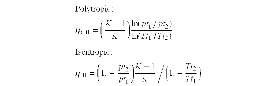
- Efficiency is defined here by 2 ways, each one based on mass-averaged conditions at cascade station upstream (1) and downstream (2):
- 1) Total to total isentropic efficiency

- Tt, pt represent total absolute temperature and total absolute pressure, k=cp/cv=1.3 for superheated steam.
- 2) Total-to-total efficiency
- For various blade heights and fixed chord 47.8 mm (axial chord=40 mm at root, the results are as follows (machine rpm=3000): both for 3ds1_r and Cy1 blades,
Blade Height Case ηtt η_tt ηp_tt mm Cy1 .883 .884 .881 30 Cy1 .873 .76 .76 63.4 3ds1_r .855 .851 .848 31.7 3ds1_r .889 .885 .833 38.4 3ds1_r .915 .91 .909 44.38 3ds1_r .93 .90 .904 63.4 3ds1_r .929 .925 .925 75 - and compared with the performance of a cylindrical blade ‘Cy1’.
- The invention described herein is in relation to a non-limiting embodiment and as defined by the accompanying claims.
Claims (9)
Applications Claiming Priority (2)
| Application Number | Priority Date | Filing Date | Title |
|---|---|---|---|
| IN715/DEL/01 | 2001-06-27 | ||
| IN715DE2001 | 2001-06-27 |
Related Parent Applications (1)
| Application Number | Title | Priority Date | Filing Date |
|---|---|---|---|
| PCT/GB2000/004934 Continuation-In-Part WO2001047043A1 (en) | 1999-12-21 | 2000-12-21 | Solution processed devices |
Related Child Applications (1)
| Application Number | Title | Priority Date | Filing Date |
|---|---|---|---|
| US11/135,278 Division US7635857B2 (en) | 1999-12-21 | 2005-05-24 | Transistor having soluble layers |
Publications (2)
| Publication Number | Publication Date |
|---|---|
| US20030086788A1 true US20030086788A1 (en) | 2003-05-08 |
| US6709239B2 US6709239B2 (en) | 2004-03-23 |
Family
ID=11097077
Family Applications (1)
| Application Number | Title | Priority Date | Filing Date |
|---|---|---|---|
| US10/176,077 Expired - Fee Related US6709239B2 (en) | 2001-06-27 | 2002-06-21 | Three dimensional blade |
Country Status (1)
| Country | Link |
|---|---|
| US (1) | US6709239B2 (en) |
Cited By (40)
| Publication number | Priority date | Publication date | Assignee | Title |
|---|---|---|---|---|
| GB2407136A (en) * | 2003-10-15 | 2005-04-20 | Alstom | A rotor blade for a gas turbine engine |
| EP1742160A1 (en) * | 2005-07-08 | 2007-01-10 | Ansaldo Energia S.P.A. | Method for optimization of blade profiles |
| WO2007010329A1 (en) * | 2005-07-15 | 2007-01-25 | Vestas Wind Systems A/S | Wind turbine blade |
| WO2007113149A1 (en) * | 2006-03-31 | 2007-10-11 | Alstom Technology Ltd | Guide blade for turbomachinery, in particular for a steam turbine |
| EP2075408A3 (en) * | 2007-12-28 | 2013-03-06 | Ansaldo Energia S.P.A. | Last stage stator blade of a steam turbine low-pressure section |
| CN103541774A (en) * | 2013-11-14 | 2014-01-29 | 上海汽轮机厂有限公司 | Method for designing turbine blades |
| WO2014143267A1 (en) * | 2013-03-15 | 2014-09-18 | United Technologies Corporation | Gas turbine engine with low fan noise |
| CN104411982A (en) * | 2012-07-06 | 2015-03-11 | 斯奈克玛 | Turbine guide vanes with improved blade profile |
| US20150233250A1 (en) * | 2014-02-19 | 2015-08-20 | United Technologies Corporation | Gas turbine engine airfoil |
| US9140127B2 (en) | 2014-02-19 | 2015-09-22 | United Technologies Corporation | Gas turbine engine airfoil |
| US9163517B2 (en) | 2014-02-19 | 2015-10-20 | United Technologies Corporation | Gas turbine engine airfoil |
| US20160063139A1 (en) * | 2013-04-16 | 2016-03-03 | Snecma | Method for modelling a part, in particular a blading |
| US9347323B2 (en) | 2014-02-19 | 2016-05-24 | United Technologies Corporation | Gas turbine engine airfoil total chord relative to span |
| US9353628B2 (en) | 2014-02-19 | 2016-05-31 | United Technologies Corporation | Gas turbine engine airfoil |
| CN104411982B (en) * | 2012-07-06 | 2016-11-30 | 斯奈克玛 | Turbine guide vanes with improved blade profile |
| US9567858B2 (en) | 2014-02-19 | 2017-02-14 | United Technologies Corporation | Gas turbine engine airfoil |
| US9599064B2 (en) | 2014-02-19 | 2017-03-21 | United Technologies Corporation | Gas turbine engine airfoil |
| US9605542B2 (en) | 2014-02-19 | 2017-03-28 | United Technologies Corporation | Gas turbine engine airfoil |
| US20180003189A1 (en) * | 2016-06-29 | 2018-01-04 | Rolls-Royce Corporation | Pressure recovery axial-compressor blading |
| US10036257B2 (en) | 2014-02-19 | 2018-07-31 | United Technologies Corporation | Gas turbine engine airfoil |
| CN108757046A (en) * | 2018-06-29 | 2018-11-06 | 东方电气集团东方汽轮机有限公司 | A kind of turbine blade |
| CN109163159A (en) * | 2018-09-17 | 2019-01-08 | 福建龙净环保股份有限公司 | Diversion component and preparation method thereof for variable cross-section elbow |
| US10352331B2 (en) | 2014-02-19 | 2019-07-16 | United Technologies Corporation | Gas turbine engine airfoil |
| US10385866B2 (en) | 2014-02-19 | 2019-08-20 | United Technologies Corporation | Gas turbine engine airfoil |
| US10393139B2 (en) | 2014-02-19 | 2019-08-27 | United Technologies Corporation | Gas turbine engine airfoil |
| US10422226B2 (en) | 2014-02-19 | 2019-09-24 | United Technologies Corporation | Gas turbine engine airfoil |
| US10465702B2 (en) | 2014-02-19 | 2019-11-05 | United Technologies Corporation | Gas turbine engine airfoil |
| US10495106B2 (en) | 2014-02-19 | 2019-12-03 | United Technologies Corporation | Gas turbine engine airfoil |
| US10502229B2 (en) | 2014-02-19 | 2019-12-10 | United Technologies Corporation | Gas turbine engine airfoil |
| US10519971B2 (en) | 2014-02-19 | 2019-12-31 | United Technologies Corporation | Gas turbine engine airfoil |
| US10557477B2 (en) | 2014-02-19 | 2020-02-11 | United Technologies Corporation | Gas turbine engine airfoil |
| US10570915B2 (en) | 2014-02-19 | 2020-02-25 | United Technologies Corporation | Gas turbine engine airfoil |
| US10570916B2 (en) | 2014-02-19 | 2020-02-25 | United Technologies Corporation | Gas turbine engine airfoil |
| US10584715B2 (en) | 2014-02-19 | 2020-03-10 | United Technologies Corporation | Gas turbine engine airfoil |
| US10590775B2 (en) | 2014-02-19 | 2020-03-17 | United Technologies Corporation | Gas turbine engine airfoil |
| US10605259B2 (en) | 2014-02-19 | 2020-03-31 | United Technologies Corporation | Gas turbine engine airfoil |
| US10697302B2 (en) | 2017-05-16 | 2020-06-30 | Rolls-Royce Plc | Compressor aerofoil member |
| CN111566317A (en) * | 2018-01-11 | 2020-08-21 | 西门子股份公司 | Gas turbine bucket and method for making bucket |
| US11220909B2 (en) * | 2014-06-26 | 2022-01-11 | Mitsubishi Heavy Industries, Ltd. | Turbine rotor blade row, turbine stage, and axial-flow turbine |
| US11454120B2 (en) * | 2018-12-07 | 2022-09-27 | General Electric Company | Turbine airfoil profile |
Families Citing this family (24)
| Publication number | Priority date | Publication date | Assignee | Title |
|---|---|---|---|---|
| NZ511661A (en) * | 2001-05-11 | 2003-09-26 | Graham Bond Grove | An improved aerofoil |
| US7179058B2 (en) * | 2004-03-21 | 2007-02-20 | Bharat Heavy Electricals Limited | Aerodynamically wide range applicable cylindrical blade profiles |
| US7175393B2 (en) * | 2004-03-31 | 2007-02-13 | Bharat Heavy Electricals Limited | Transonic blade profiles |
| US6994520B2 (en) * | 2004-05-26 | 2006-02-07 | General Electric Company | Internal core profile for a turbine nozzle airfoil |
| US7186090B2 (en) * | 2004-08-05 | 2007-03-06 | General Electric Company | Air foil shape for a compressor blade |
| US20070231141A1 (en) * | 2006-03-31 | 2007-10-04 | Honeywell International, Inc. | Radial turbine wheel with locally curved trailing edge tip |
| WO2008109036A1 (en) * | 2007-03-05 | 2008-09-12 | Xcelaero Corporation | High efficiency cooling fan |
| US8157518B2 (en) * | 2007-03-05 | 2012-04-17 | Xcelaero Corporation | Low camber microfan |
| GB0704426D0 (en) * | 2007-03-08 | 2007-04-18 | Rolls Royce Plc | Aerofoil members for a turbomachine |
| US8491253B2 (en) * | 2008-11-03 | 2013-07-23 | Energent Corporation | Two-phase, axial flow, turbine apparatus |
| US9121412B2 (en) | 2011-07-05 | 2015-09-01 | United Technologies Corporation | Efficient, low pressure ratio propulsor for gas turbine engines |
| US9506422B2 (en) | 2011-07-05 | 2016-11-29 | United Technologies Corporation | Efficient, low pressure ratio propulsor for gas turbine engines |
| US9909505B2 (en) | 2011-07-05 | 2018-03-06 | United Technologies Corporation | Efficient, low pressure ratio propulsor for gas turbine engines |
| US8894376B2 (en) | 2011-10-28 | 2014-11-25 | General Electric Company | Turbomachine blade with tip flare |
| JP6468414B2 (en) * | 2014-08-12 | 2019-02-13 | 株式会社Ihi | Compressor vane, axial compressor, and gas turbine |
| US9470093B2 (en) | 2015-03-18 | 2016-10-18 | United Technologies Corporation | Turbofan arrangement with blade channel variations |
| JP6421091B2 (en) * | 2015-07-30 | 2018-11-07 | 三菱日立パワーシステムズ株式会社 | Axial flow compressor, gas turbine including the same, and stationary blade of axial flow compressor |
| US9957805B2 (en) * | 2015-12-18 | 2018-05-01 | General Electric Company | Turbomachine and turbine blade therefor |
| DE102016115868A1 (en) * | 2016-08-26 | 2018-03-01 | Rolls-Royce Deutschland Ltd & Co Kg | High-efficiency fluid flow machine |
| IT202000005146A1 (en) | 2020-03-11 | 2021-09-11 | Ge Avio Srl | TURBINE ENGINE WITH AERODYNAMIC PROFILE HAVING HIGH ACCELERATION AND LOW VANE CURVE |
| US11795824B2 (en) | 2021-11-30 | 2023-10-24 | General Electric Company | Airfoil profile for a blade in a turbine engine |
| US12071889B2 (en) | 2022-04-05 | 2024-08-27 | General Electric Company | Counter-rotating turbine |
| US12497917B2 (en) | 2022-05-18 | 2025-12-16 | General Electric Company | Counter-rotating turbine |
| US12326118B2 (en) | 2022-09-16 | 2025-06-10 | General Electric Company | Gas turbine engines with a fuel cell assembly |
Citations (4)
| Publication number | Priority date | Publication date | Assignee | Title |
|---|---|---|---|---|
| US4585395A (en) * | 1983-12-12 | 1986-04-29 | General Electric Company | Gas turbine engine blade |
| US6071077A (en) * | 1996-04-09 | 2000-06-06 | Rolls-Royce Plc | Swept fan blade |
| US6299412B1 (en) * | 1999-12-06 | 2001-10-09 | General Electric Company | Bowed compressor airfoil |
| US6331100B1 (en) * | 1999-12-06 | 2001-12-18 | General Electric Company | Doubled bowed compressor airfoil |
-
2002
- 2002-06-21 US US10/176,077 patent/US6709239B2/en not_active Expired - Fee Related
Patent Citations (4)
| Publication number | Priority date | Publication date | Assignee | Title |
|---|---|---|---|---|
| US4585395A (en) * | 1983-12-12 | 1986-04-29 | General Electric Company | Gas turbine engine blade |
| US6071077A (en) * | 1996-04-09 | 2000-06-06 | Rolls-Royce Plc | Swept fan blade |
| US6299412B1 (en) * | 1999-12-06 | 2001-10-09 | General Electric Company | Bowed compressor airfoil |
| US6331100B1 (en) * | 1999-12-06 | 2001-12-18 | General Electric Company | Doubled bowed compressor airfoil |
Cited By (74)
| Publication number | Priority date | Publication date | Assignee | Title |
|---|---|---|---|---|
| GB2407136A (en) * | 2003-10-15 | 2005-04-20 | Alstom | A rotor blade for a gas turbine engine |
| US20050106027A1 (en) * | 2003-10-15 | 2005-05-19 | Harvey Neil W. | Turbine rotor blade for gas turbine engine |
| US7217101B2 (en) | 2003-10-15 | 2007-05-15 | Alstom Technology Ltd. | Turbine rotor blade for gas turbine engine |
| GB2407136B (en) * | 2003-10-15 | 2007-10-03 | Alstom | Turbine rotor blade for gas turbine engine |
| EP1524405A3 (en) * | 2003-10-15 | 2012-06-13 | Alstom Technology Ltd | Turbine rotor blade for gas turbine engine |
| EP1742160A1 (en) * | 2005-07-08 | 2007-01-10 | Ansaldo Energia S.P.A. | Method for optimization of blade profiles |
| WO2007010329A1 (en) * | 2005-07-15 | 2007-01-25 | Vestas Wind Systems A/S | Wind turbine blade |
| US20090202354A1 (en) * | 2005-07-15 | 2009-08-13 | Kristian Balschmidt Godsk | Wind turbine blade |
| US8142162B2 (en) | 2005-07-15 | 2012-03-27 | Vestas Wind Systems A/S | Wind turbine blade |
| JP2009531593A (en) * | 2006-03-31 | 2009-09-03 | アルストム テクノロジー リミテッド | Guide blades for fluid machinery, especially steam turbines |
| US20090257866A1 (en) * | 2006-03-31 | 2009-10-15 | Alstom Technology Ltd. | Stator blade for a turbomachine, especially a steam turbine |
| US20110164970A1 (en) * | 2006-03-31 | 2011-07-07 | Alstom Technology Ltd | Stator blade for a turbomachine, especially a stream turbine |
| WO2007113149A1 (en) * | 2006-03-31 | 2007-10-11 | Alstom Technology Ltd | Guide blade for turbomachinery, in particular for a steam turbine |
| EP2075408A3 (en) * | 2007-12-28 | 2013-03-06 | Ansaldo Energia S.P.A. | Last stage stator blade of a steam turbine low-pressure section |
| CN104411982A (en) * | 2012-07-06 | 2015-03-11 | 斯奈克玛 | Turbine guide vanes with improved blade profile |
| CN104411982B (en) * | 2012-07-06 | 2016-11-30 | 斯奈克玛 | Turbine guide vanes with improved blade profile |
| WO2014143267A1 (en) * | 2013-03-15 | 2014-09-18 | United Technologies Corporation | Gas turbine engine with low fan noise |
| US20160063139A1 (en) * | 2013-04-16 | 2016-03-03 | Snecma | Method for modelling a part, in particular a blading |
| US10002209B2 (en) * | 2013-04-16 | 2018-06-19 | Snecma | Method for modelling a part, in particular a blading |
| CN103541774A (en) * | 2013-11-14 | 2014-01-29 | 上海汽轮机厂有限公司 | Method for designing turbine blades |
| US10036257B2 (en) | 2014-02-19 | 2018-07-31 | United Technologies Corporation | Gas turbine engine airfoil |
| US10465702B2 (en) | 2014-02-19 | 2019-11-05 | United Technologies Corporation | Gas turbine engine airfoil |
| US9353628B2 (en) | 2014-02-19 | 2016-05-31 | United Technologies Corporation | Gas turbine engine airfoil |
| US9399917B2 (en) | 2014-02-19 | 2016-07-26 | United Technologies Corporation | Gas turbine engine airfoil |
| US9482097B2 (en) | 2014-02-19 | 2016-11-01 | United Technologies Corporation | Gas turbine engine airfoil |
| US9163517B2 (en) | 2014-02-19 | 2015-10-20 | United Technologies Corporation | Gas turbine engine airfoil |
| US9567858B2 (en) | 2014-02-19 | 2017-02-14 | United Technologies Corporation | Gas turbine engine airfoil |
| US9574574B2 (en) | 2014-02-19 | 2017-02-21 | United Technologies Corporation | Gas turbine engine airfoil |
| EP3108102A4 (en) * | 2014-02-19 | 2017-02-22 | United Technologies Corporation | Gas turbine engine airfoil |
| US9599064B2 (en) | 2014-02-19 | 2017-03-21 | United Technologies Corporation | Gas turbine engine airfoil |
| US9605542B2 (en) | 2014-02-19 | 2017-03-28 | United Technologies Corporation | Gas turbine engine airfoil |
| US9752439B2 (en) | 2014-02-19 | 2017-09-05 | United Technologies Corporation | Gas turbine engine airfoil |
| US9777580B2 (en) | 2014-02-19 | 2017-10-03 | United Technologies Corporation | Gas turbine engine airfoil |
| US11867195B2 (en) | 2014-02-19 | 2024-01-09 | Rtx Corporation | Gas turbine engine airfoil |
| US9988908B2 (en) | 2014-02-19 | 2018-06-05 | United Technologies Corporation | Gas turbine engine airfoil |
| US9140127B2 (en) | 2014-02-19 | 2015-09-22 | United Technologies Corporation | Gas turbine engine airfoil |
| US20150233250A1 (en) * | 2014-02-19 | 2015-08-20 | United Technologies Corporation | Gas turbine engine airfoil |
| US11767856B2 (en) | 2014-02-19 | 2023-09-26 | Rtx Corporation | Gas turbine engine airfoil |
| US11408436B2 (en) | 2014-02-19 | 2022-08-09 | Raytheon Technologies Corporation | Gas turbine engine airfoil |
| US10184483B2 (en) | 2014-02-19 | 2019-01-22 | United Technologies Corporation | Gas turbine engine airfoil |
| US10309414B2 (en) | 2014-02-19 | 2019-06-04 | United Technologies Corporation | Gas turbine engine airfoil |
| US10352331B2 (en) | 2014-02-19 | 2019-07-16 | United Technologies Corporation | Gas turbine engine airfoil |
| US10358925B2 (en) | 2014-02-19 | 2019-07-23 | United Technologies Corporation | Gas turbine engine airfoil |
| US10370974B2 (en) | 2014-02-19 | 2019-08-06 | United Technologies Corporation | Gas turbine engine airfoil |
| US10385866B2 (en) | 2014-02-19 | 2019-08-20 | United Technologies Corporation | Gas turbine engine airfoil |
| US10393139B2 (en) | 2014-02-19 | 2019-08-27 | United Technologies Corporation | Gas turbine engine airfoil |
| US10422226B2 (en) | 2014-02-19 | 2019-09-24 | United Technologies Corporation | Gas turbine engine airfoil |
| US9347323B2 (en) | 2014-02-19 | 2016-05-24 | United Technologies Corporation | Gas turbine engine airfoil total chord relative to span |
| US10495106B2 (en) | 2014-02-19 | 2019-12-03 | United Technologies Corporation | Gas turbine engine airfoil |
| US10502229B2 (en) | 2014-02-19 | 2019-12-10 | United Technologies Corporation | Gas turbine engine airfoil |
| US10519971B2 (en) | 2014-02-19 | 2019-12-31 | United Technologies Corporation | Gas turbine engine airfoil |
| US10550852B2 (en) | 2014-02-19 | 2020-02-04 | United Technologies Corporation | Gas turbine engine airfoil |
| US10557477B2 (en) | 2014-02-19 | 2020-02-11 | United Technologies Corporation | Gas turbine engine airfoil |
| US10570915B2 (en) | 2014-02-19 | 2020-02-25 | United Technologies Corporation | Gas turbine engine airfoil |
| US10570916B2 (en) | 2014-02-19 | 2020-02-25 | United Technologies Corporation | Gas turbine engine airfoil |
| US10584715B2 (en) | 2014-02-19 | 2020-03-10 | United Technologies Corporation | Gas turbine engine airfoil |
| US10590775B2 (en) | 2014-02-19 | 2020-03-17 | United Technologies Corporation | Gas turbine engine airfoil |
| US10605259B2 (en) | 2014-02-19 | 2020-03-31 | United Technologies Corporation | Gas turbine engine airfoil |
| US11391294B2 (en) | 2014-02-19 | 2022-07-19 | Raytheon Technologies Corporation | Gas turbine engine airfoil |
| US11209013B2 (en) | 2014-02-19 | 2021-12-28 | Raytheon Technologies Corporation | Gas turbine engine airfoil |
| US11193497B2 (en) | 2014-02-19 | 2021-12-07 | Raytheon Technologies Corporation | Gas turbine engine airfoil |
| US10890195B2 (en) | 2014-02-19 | 2021-01-12 | Raytheon Technologies Corporation | Gas turbine engine airfoil |
| US10914315B2 (en) | 2014-02-19 | 2021-02-09 | Raytheon Technologies Corporation | Gas turbine engine airfoil |
| US11193496B2 (en) | 2014-02-19 | 2021-12-07 | Raytheon Technologies Corporation | Gas turbine engine airfoil |
| US11041507B2 (en) | 2014-02-19 | 2021-06-22 | Raytheon Technologies Corporation | Gas turbine engine airfoil |
| US11220909B2 (en) * | 2014-06-26 | 2022-01-11 | Mitsubishi Heavy Industries, Ltd. | Turbine rotor blade row, turbine stage, and axial-flow turbine |
| US10935041B2 (en) * | 2016-06-29 | 2021-03-02 | Rolls-Royce Corporation | Pressure recovery axial-compressor blading |
| US20180003189A1 (en) * | 2016-06-29 | 2018-01-04 | Rolls-Royce Corporation | Pressure recovery axial-compressor blading |
| US10697302B2 (en) | 2017-05-16 | 2020-06-30 | Rolls-Royce Plc | Compressor aerofoil member |
| CN111566317A (en) * | 2018-01-11 | 2020-08-21 | 西门子股份公司 | Gas turbine bucket and method for making bucket |
| CN108757046A (en) * | 2018-06-29 | 2018-11-06 | 东方电气集团东方汽轮机有限公司 | A kind of turbine blade |
| CN109163159B (en) * | 2018-09-17 | 2020-08-28 | 福建龙净环保股份有限公司 | Flow guide part for variable cross-section elbow and manufacturing method thereof |
| CN109163159A (en) * | 2018-09-17 | 2019-01-08 | 福建龙净环保股份有限公司 | Diversion component and preparation method thereof for variable cross-section elbow |
| US11454120B2 (en) * | 2018-12-07 | 2022-09-27 | General Electric Company | Turbine airfoil profile |
Also Published As
| Publication number | Publication date |
|---|---|
| US6709239B2 (en) | 2004-03-23 |
Similar Documents
| Publication | Publication Date | Title |
|---|---|---|
| US6709239B2 (en) | Three dimensional blade | |
| US7175393B2 (en) | Transonic blade profiles | |
| US5352092A (en) | Light weight steam turbine blade | |
| CN107636316B (en) | Offset passages in a diffuser and corresponding method of designing the diffuser | |
| US6491493B1 (en) | Turbine nozzle vane | |
| US5524341A (en) | Method of making a row of mix-tuned turbomachine blades | |
| RU2228461C2 (en) | Double-bend formed-to-shape blade of compressor | |
| US5779443A (en) | Turbine blade | |
| US5480285A (en) | Steam turbine blade | |
| EP0985801B1 (en) | Blade configuration for steam turbine | |
| US4919593A (en) | Retrofitted rotor blades for steam turbines and method of making the same | |
| US6338610B1 (en) | Centrifugal turbomachinery | |
| RU2666933C1 (en) | Turbomachine component or collection of components and associated turbomachine | |
| US20090257866A1 (en) | Stator blade for a turbomachine, especially a steam turbine | |
| JPH05340201A (en) | Tapered torsion blades and blade arrays in turbines | |
| KR910010034B1 (en) | Rotor blade form for the first stage of a combustion turbiine | |
| JP7104379B2 (en) | Axial flow type fan, compressor and turbine blade design method, and blades obtained by the design | |
| US6682301B2 (en) | Reduced shock transonic airfoil | |
| EP2339115A2 (en) | Turbine rotor assembly and steam turbine | |
| JPH0361603A (en) | Steam turbine blade row structure | |
| JPH03138404A (en) | Blades for steam turbines | |
| US6431829B1 (en) | Turbine device | |
| US7179058B2 (en) | Aerodynamically wide range applicable cylindrical blade profiles | |
| EP0023025A1 (en) | A turbine blade | |
| US6979178B2 (en) | Cylindrical blades for axial steam turbines |
Legal Events
| Date | Code | Title | Description |
|---|---|---|---|
| AS | Assignment |
Owner name: BHARAT HEAVY ELECTRICALS LTD., INDIA Free format text: ASSIGNMENT OF ASSIGNORS INTEREST;ASSIGNOR:CHANDRAKER, A.L.;REEL/FRAME:013028/0115 Effective date: 20020523 |
|
| CC | Certificate of correction | ||
| FPAY | Fee payment |
Year of fee payment: 4 |
|
| FEPP | Fee payment procedure |
Free format text: PAYOR NUMBER ASSIGNED (ORIGINAL EVENT CODE: ASPN); ENTITY STATUS OF PATENT OWNER: LARGE ENTITY |
|
| REMI | Maintenance fee reminder mailed | ||
| FPAY | Fee payment |
Year of fee payment: 8 |
|
| SULP | Surcharge for late payment |
Year of fee payment: 7 |
|
| REMI | Maintenance fee reminder mailed | ||
| LAPS | Lapse for failure to pay maintenance fees | ||
| STCH | Information on status: patent discontinuation |
Free format text: PATENT EXPIRED DUE TO NONPAYMENT OF MAINTENANCE FEES UNDER 37 CFR 1.362 |
|
| STCH | Information on status: patent discontinuation |
Free format text: PATENT EXPIRED DUE TO NONPAYMENT OF MAINTENANCE FEES UNDER 37 CFR 1.362 |
|
| FP | Lapsed due to failure to pay maintenance fee |
Effective date: 20160323 |