US2002576A - Extension table - Google Patents
Extension table Download PDFInfo
- Publication number
- US2002576A US2002576A US688202A US68820233A US2002576A US 2002576 A US2002576 A US 2002576A US 688202 A US688202 A US 688202A US 68820233 A US68820233 A US 68820233A US 2002576 A US2002576 A US 2002576A
- Authority
- US
- United States
- Prior art keywords
- extension
- channel
- brackets
- rollers
- bars
- Prior art date
- Legal status (The legal status is an assumption and is not a legal conclusion. Google has not performed a legal analysis and makes no representation as to the accuracy of the status listed.)
- Expired - Lifetime
Links
Images


Classifications
-
- A—HUMAN NECESSITIES
- A47—FURNITURE; DOMESTIC ARTICLES OR APPLIANCES; COFFEE MILLS; SPICE MILLS; SUCTION CLEANERS IN GENERAL
- A47B—TABLES; DESKS; OFFICE FURNITURE; CABINETS; DRAWERS; GENERAL DETAILS OF FURNITURE
- A47B1/00—Extensible tables
- A47B1/02—Extensible tables with insertable leaves arranged in the centre and fixed frames
-
- F—MECHANICAL ENGINEERING; LIGHTING; HEATING; WEAPONS; BLASTING
- F16—ENGINEERING ELEMENTS AND UNITS; GENERAL MEASURES FOR PRODUCING AND MAINTAINING EFFECTIVE FUNCTIONING OF MACHINES OR INSTALLATIONS; THERMAL INSULATION IN GENERAL
- F16C—SHAFTS; FLEXIBLE SHAFTS; ELEMENTS OR CRANKSHAFT MECHANISMS; ROTARY BODIES OTHER THAN GEARING ELEMENTS; BEARINGS
- F16C33/00—Parts of bearings; Special methods for making bearings or parts thereof
- F16C33/30—Parts of ball or roller bearings
- F16C33/306—Means to synchronise movements
Definitions
- This invention relates to an extension table having therein improved non-friction roller means movable with the top section or extension leaves, for supporting the top section or extension leaves of the table so that the same may be extended or moved to folded position with a mini mum amount of effort.
- the extension leaves or top sections are mounted on Suitable rollers mounted in suitable trackways or channel members sothat a minimum amount of friction is eneountered in moving the extension leaves or top sections of the table with relation to the trackways on which"1they are mounted.
- Figure 1 is aside elevation of an extension table in extended position and showing the unit extension structure hereinafter set forth
- Figure2 is a plan view of the unit for an extension table 'with the table framework and the top sections attachable thereto omitted, except 'the foldableleaf
- Figure 3 is an isometric view of thecentral por Winston-Salem, N. 0. September 5, 1933, Serial No. 688,202
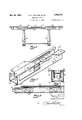
- Figure 7 is an isometric view, with portions broken away, of the central portion ofEone of the channel bars showing a modified form of the invention and. showing a portion of the brackets for supporting the top sections;
- Figure 8 is a longitudinal view, with portions broken away, of one end of one of the modified channel bars and showing the brackets and rollers supporting one of the top sections;
- Figure 9 is a view looking into the nearest end of Figure 7;
- Figure 10 is an isometric view of the central portion of one of the supporting bars for another slightly modified form of' the invention.
- Figure 11 is a longitudinal sectional view show ing one end of the structure supporting the form shown in Figure 10;
- Figure 12 is a view looking into the nearest end of Figure 10;
- Figure 13 is a view similar to Figure 12 and showing a slightly modified form of the structure over that shown in Figures 10, 11 and 12.
- Figure 14 is 'a view similar to Figure 12but to limit outward movement of the brackets carrying the extension leaves.
- These channel bars are held in parallel relation by means of bars ll and L8 disposed between the ends of the channel bars and also by the angle bars 89' and 20 which not only serve to space the channel bars H and I2 in parallel relation but alsomakethe foldable leaves supporting structure integral with the remainder of the unit so that the entire unit can be manufactured and sold to furniture factories and installed on the table framework.
- This foldable leaf supporting structure comprising bars l9 and 2!], pivotally supports a transverse rod 2! which has bent portions 22 therein and which is secured by any suitable means such as screws 23 to the foldable leaf 24 which is shown in folded position in Figures 2 and 5.
- These angle bars l9 and 28 have mounted thereon the upstanding lugs 25 and 26 in which the transverse rod 2% is rotatably mounted.
- the angle bars l9 and 2E! also have the upstanding inturned brackets 2'! and 28 which support the open end of the folded leaf 24' in the position shown in Figure so that top sections 29 and 38 may be moved thereover when the foldable leaf 2 5 is in folded position.
- the length of members H and i2 may be increased and a greater number of foldable leaves placed in position, if desired.
- the leaf 29 is shown in section and has attached to the lower surface thereof, a plate 32 which has integral therewith, downturned and inwardly projecting arms or brackets 33 and 34, which have rotatably mounted therein a roller 35.
- the channel members H and I2 are identical and are composed of the upper portion 35 and the bottom portion 31.
- the upper portion 36 has a longitudinally and centrally disposed groove 38 therein and the bottom portion has a longitudinally and centrally disposed groove 39 therein in which the rounded periphery of roller 35 travels, and which restricts the upward, downward and lateral movement of roller 35.
- Each of these channel bars I! and I2 have mounted centrally thereof a bracketlfiwhich has mounted thereon a pinion 4! which meshes with racks 42 and 43, rack 42 being secured to arm or bracket 33 and associated with roller 35, whereas, rack 43 is secured to one of the arms or brackets of a bracket 45, the latter carrying the downwardly and inwardly projecting arms or brackets 46 and t? in which is rotatably mounted a roller 48 which also travels in the grooves 38 and 39.
- the top section 29 has pins 54 therein adapted to penetrate coinciding holes in the foldable leaf 24 when the same is in unfolded position and the foldable leaf also has pins 55 therein adapted to enter coinciding holes in the extension leaf 3% also when the foldable leaf 24 is in unfolded position and ready for use. This supports the unfolded center leaf.
- a channel bar 69 which is U-shaped in cross-section, is provided and has not only inturned upper edges, but these edges are also downturned as indicated at (it and 62, forming channels 53 and 64 which coincide with channels 55 and 66 in the bottom portion of the channel bars.
- a bracket 6? is mounted having rollers 68 and 69 thereon, which roll in and are confined in channels 64 and 66 and channels 63 and 65, limiting the upward, lateral and downward movement of members 61 and 61.
- Bracket 81 has portion Iii projecting toward the central portion of the, framework and has a plurality of equally spaced holes H therein serving as a rack for engaging a centrally dis posed pinion 12 mounted on an upstanding support 13.
- the upper portion ofthe bracket 61 is turned laterally as at 14 and has holes therein whereby wood screws may penetrate same and be embedded in the extension leaf 15.
- the channel bars have their ends closed by any suitable means, such as caps 16.
- any suitable means such as caps 16.
- caps 16 The above description for the structure shown in Figure 3 equally applies to the brackets disposed on the other end of each of the channel bars, a portion of the other bracket being shown in Figure 7 and being indicated by like reference characters with the prime notations added.
- one of the extension leaf supports corresponding to channel member H or 12 of Figure 2
- one of the extension leaf supports comprises upper and lower parallel rails BDand 8!, which are held in spaced relation by suitable straps 83 near each end, and by a suitable cap 84 over each end.
- On each end of each extension leaf support means are provided for supporting the ex tension leaf 85 of the table, said means comprising two brackets, each bracket having depending legs 86 and 81 which engage opposite sides of the upper rail 3! and thereby guide the bracket.
- a roller 88 is mounted in the lower ends of the legs of each bracket and is in contact with the top surface of rail 85, and is confined between the rails 80 and 8! to limit upward and downward movement of the bracket.
- a plate 90 is welded to the bracket nearest the center of the table and a plate 89 is welded to the remaining bracket.
- the bracket nearest thecenter of the table also carries a rack 9
- FIG 13 a slightly modified form of the in vention, as shown in Figures 10, 11 and 12, is shown, the only difference being, that the upper rail 81 has a suitable channel 94 therein in which a pinion 92 and the racks 9
- the channel does not extend the entire length of the upper rail 8
- rollers 86b and 811) are provided for taking care of lateral thrusts.
- a table slide for an extension table having two slidable top sections comprising two, spaced parallel members adapted to be rigidly mounted on said table, each of said members comprisingv upper and lower bars spaced from each other and forming a guideway therebetween, a plurality of rollers positioned in each guideway, each roller being carried by a bracket which is adapted to be secured to the lower surface of one of the top sections, each of said brackets comprising a pair of depending arms positioned on each side of said upper bar to limit lateral movement of the bracket, there being at least two of said brackets associated with each top section and adapted to be positioned near the meeting edge of each top section, the brackets of one top section confronting those associated with the other section, and equalizer means associated with each of the confronting brackets and said parallel members.
- said equalizer means comprising a pinion mounted on one of the bars of each parallel member and a rack mounted on one arm of each confronting bracket.
Landscapes
- Engineering & Computer Science (AREA)
- General Engineering & Computer Science (AREA)
- Mechanical Engineering (AREA)
- Legs For Furniture In General (AREA)
Description
May 28, 1935.
R. A. HOLLAND El Al.
EXTENSION TABLE Filed Sept. 5, 1933 4 Sheets-Sheet UUUDUDDUUUD $7M, M mm AH T R a 0 R AND ALFRED H. Hum/-11: g /i May 28, 1935. R. A. HoLL AND ET AL EXTENSION TABLE Filed Sept. 5, 1933 4 Shets-Sheet 2 May 28, 1935. R? HOLLAND ET AL 2,002,576
EXTENSION TABLE Filed Sept. s, 1933 4 Sheets-Sheet s amen WOW. Rose/e1 Fl HoLLn/vo AND AL FRED H Hum/v0 y 1935- R. A. HOLLAND ET AL 2,002,576
I EXTENSION TABLE Filed Sept. 5, 1933 4 Sheets-Sheet 4 VZEIMV/IE ROBERT A. HOLLAND AND ALFRED H HOLLAND Patented May 28, 1935 EXTENSION TABLE vRobert A. Holland and Alfred H. Holland,
This invention relates to an extension table having therein improved non-friction roller means movable with the top section or extension leaves, for supporting the top section or extension leaves of the table so that the same may be extended or moved to folded position with a mini mum amount of effort. The extension leaves or top sections are mounted on Suitable rollers mounted in suitable trackways or channel members sothat a minimum amount of friction is eneountered in moving the extension leaves or top sections of the table with relation to the trackways on which"1they are mounted. p I t It is an objecit of this invention to provide an extension table having a unit structure adapted to be placed'on top' oia table framework and having a pair of parallel trackways therein for guiding a plurality of rollers, said rollersbeing mounted on brackets' which" are attached to the lower side of the top'sectionsrso that the roller and. top sections move with relation to the channel'member when the top sections are moved to open or closed position; l
It is a. further object of this invention to provide rollers for supporting extension leaves or 7 top sections of a table with parallel channel members for'supporting the rollers so that the rollers move with the top sections with relation to the channel members and suitable rack members are secured to the brackets carrying the rollers and engagea common pinion for each channel bar so that movement imparted to one extension leaf or top section willcause movement in a reverse direction of the other extension leaf or top section.
It is a furtherobject of invention to pro vide an extension table h'avingchannel bars provided with rollers contacting the channel bars and secured on the bottom surfaces of the top sections for rotation, which rollers not only reduce friction, but also prevent lateral and vertical movement of the top sections with relation to the channel bars.
Some of the objects of the invention having been stated, the'invention will appear more fully as to details when taken in connection with the "accompanying drawings, in which:--
Figure 1 is aside elevation of an extension table in extended position and showing the unit extension structure hereinafter set forth Figure2 is a plan view of the unit for an extension table 'with the table framework and the top sections attachable thereto omitted, except 'the foldableleaf Figure 3 is an isometric view of thecentral por Winston-Salem, N. 0. September 5, 1933, Serial No. 688,202
tion .of one of the channel bars and the proxiand showing portions supporting the foldable leaves and taken along the line 6-5 in Figure 2;
Figure 7 is an isometric view, with portions broken away, of the central portion ofEone of the channel bars showing a modified form of the invention and. showing a portion of the brackets for supporting the top sections;
Figure 8 is a longitudinal view, with portions broken away, of one end of one of the modified channel bars and showing the brackets and rollers supporting one of the top sections;
Figure 9 is a view looking into the nearest end of Figure 7; V
Figure 10 is an isometric view of the central portion of one of the supporting bars for another slightly modified form of' the invention;
Figure 11 is a longitudinal sectional view show ing one end of the structure supporting the form shown in Figure 10; I
Figure 12 is a view looking into the nearest end of Figure 10;
Figure 13 is a view similar to Figure 12 and showing a slightly modified form of the structure over that shown in Figures 10, 11 and 12.
Figure 14 is 'a view similar to Figure 12but to limit outward movement of the brackets carrying the extension leaves. These channel bars are held in parallel relation by means of bars ll and L8 disposed between the ends of the channel bars and also by the angle bars 89' and 20 which not only serve to space the channel bars H and I2 in parallel relation but alsomakethe foldable leaves supporting structure integral with the remainder of the unit so that the entire unit can be manufactured and sold to furniture factories and installed on the table framework.
This foldable leaf supporting structure, comprising bars l9 and 2!], pivotally supports a transverse rod 2! which has bent portions 22 therein and which is secured by any suitable means such as screws 23 to the foldable leaf 24 which is shown in folded position in Figures 2 and 5. These angle bars l9 and 28 have mounted thereon the upstanding lugs 25 and 26 in which the transverse rod 2% is rotatably mounted.
The angle bars l9 and 2E! also have the upstanding inturned brackets 2'! and 28 which support the open end of the folded leaf 24' in the position shown in Figure so that top sections 29 and 38 may be moved thereover when the foldable leaf 2 5 is in folded position. Although there is shown only one foldable leaf, it is evident that the length of members H and i2 may be increased and a greater number of foldable leaves placed in position, if desired. In Figure 4, the leaf 29 is shown in section and has attached to the lower surface thereof, a plate 32 which has integral therewith, downturned and inwardly projecting arms or brackets 33 and 34, which have rotatably mounted therein a roller 35. The channel members H and I2 are identical and are composed of the upper portion 35 and the bottom portion 31. 'The upper portion 36 has a longitudinally and centrally disposed groove 38 therein and the bottom portion has a longitudinally and centrally disposed groove 39 therein in which the rounded periphery of roller 35 travels, and which restricts the upward, downward and lateral movement of roller 35. Each of these channel bars I! and I2 have mounted centrally thereof a bracketlfiwhich has mounted thereon a pinion 4! which meshes with racks 42 and 43, rack 42 being secured to arm or bracket 33 and associated with roller 35, whereas, rack 43 is secured to one of the arms or brackets of a bracket 45, the latter carrying the downwardly and inwardly projecting arms or brackets 46 and t? in which is rotatably mounted a roller 48 which also travels in the grooves 38 and 39.
" The description of the members 32 and 45 and associated parts is sufiicient to describe the end members 32 and 45' because the structure of the latter differs from that of the former only in the omission of racks G2 and 43. Members 38 and 31 forming the channel members II and i2 are not only secured to each other by means of caps I3 and H! but also by members 49 and so disposed between brackets 32 and 32' and brackets 45 and 45' as to be out of the path travelled by the rollers carried thereby so that the rollers and leaves carried thereby can be opened surficiently for the foldable leaf to be manipulated, the position of the brackets in Figure 2 being that position they will occupy when the extension leaves are in extended position.
' The structure of channel bar member I2 having been described, the structure of the other similar member H is identical and therefore like reference characters will apply. The top section 29 has pins 54 therein adapted to penetrate coinciding holes in the foldable leaf 24 when the same is in unfolded position and the foldable leaf also has pins 55 therein adapted to enter coinciding holes in the extension leaf 3% also when the foldable leaf 24 is in unfolded position and ready for use. This supports the unfolded center leaf.
as it is evident that the structure of the two channel bars is identical and the central structure in both of the channel bars is identical and therefore the showing, as set forth in Figures 7, 8 and 9, will enable those skilled in the art, to reconstruct the invention, as set forth in these Figures '7, 8 and 9, according to the unit set forth in Figure 2.
In the form shown in Figures '7, 8 and 9, a channel bar 69 which is U-shaped in cross-section, is provided and has not only inturned upper edges, but these edges are also downturned as indicated at (it and 62, forming channels 53 and 64 which coincide with channels 55 and 66 in the bottom portion of the channel bars. In these channels and at opposite ends and sides of each of the channel bars 60, a bracket 6? is mounted having rollers 68 and 69 thereon, which roll in and are confined in channels 64 and 66 and channels 63 and 65, limiting the upward, lateral and downward movement of members 61 and 61.
Bracket 81 has portion Iii projecting toward the central portion of the, framework and has a plurality of equally spaced holes H therein serving as a rack for engaging a centrally dis posed pinion 12 mounted on an upstanding support 13. The upper portion ofthe bracket 61 is turned laterally as at 14 and has holes therein whereby wood screws may penetrate same and be embedded in the extension leaf 15. e
The channel bars have their ends closed by any suitable means, such as caps 16. The above description for the structure shown in Figure 3 equally applies to the brackets disposed on the other end of each of the channel bars, a portion of the other bracket being shown in Figure 7 and being indicated by like reference characters with the prime notations added.
In Figures 10, 11 and 12 there is shown a slightly modified form of the invention in which one of the extension leaf supports, corresponding to channel member H or 12 of Figure 2, comprises upper and lower parallel rails BDand 8!, which are held in spaced relation by suitable straps 83 near each end, and by a suitable cap 84 over each end. On each end of each extension leaf support, means are provided for supporting the ex tension leaf 85 of the table, said means comprising two brackets, each bracket having depending legs 86 and 81 which engage opposite sides of the upper rail 3! and thereby guide the bracket. A roller 88 is mounted in the lower ends of the legs of each bracket and is in contact with the top surface of rail 85, and is confined between the rails 80 and 8! to limit upward and downward movement of the bracket. A plate 90 is welded to the bracket nearest the center of the table and a plate 89 is welded to the remaining bracket. The bracket nearest thecenter of the table also carries a rack 9| which engages a pinion 92 mounted on a strap 82, the strap being secured to both rails and cooperating with straps 83 to hold the rails in spaced relation to provide a passageway for the rollers 88.
In Figure 13 a slightly modified form of the in vention, as shown in Figures 10, 11 and 12, is shown, the only difference being, that the upper rail 81 has a suitable channel 94 therein in which a pinion 92 and the racks 9| operate instead of being disposed on top of the rail 8i, as shown in Figures 10, 11 and 12. The channel does not extend the entire length of the upper rail 8| but only in the central portion thereof and is just long enough to permit the extension leaves to be moved to outward position.
In. all of the forms of the invention, lateral movement of the extension leaves is prevented. In Figures 10 to 13, indentations 86a and 81a on the bracket legs 86 and 81, respectively, prevent this lateral movement. In Figures 7 to 9 the upper and lower channels for the rollers, prevent this lateral movement, and in Figures 3 to 5 the channel 39 having rollers 35 and 35' prevent lateral movement of the extension leaves, and when the leaves are raised upwardly to cause the rollers 35 to engage the upper channel 38, this channel serves to prevent lateral movement of the extension leaves.
In Figure 14, instead of indentations, rollers 86b and 811) are provided for taking care of lateral thrusts.
We claim:
1. A table slide for an extension table having two slidable top sections comprising two, spaced parallel members adapted to be rigidly mounted on said table, each of said members comprisingv upper and lower bars spaced from each other and forming a guideway therebetween, a plurality of rollers positioned in each guideway, each roller being carried by a bracket which is adapted to be secured to the lower surface of one of the top sections, each of said brackets comprising a pair of depending arms positioned on each side of said upper bar to limit lateral movement of the bracket, there being at least two of said brackets associated with each top section and adapted to be positioned near the meeting edge of each top section, the brackets of one top section confronting those associated with the other section, and equalizer means associated with each of the confronting brackets and said parallel members.
2. A table slide as recited in claim 1, said equalizer means comprising a pinion mounted on one of the bars of each parallel member and a rack mounted on one arm of each confronting bracket.
ALFRED H. HOLLAND.
Priority Applications (1)
| Application Number | Priority Date | Filing Date | Title |
|---|---|---|---|
| US688202A US2002576A (en) | 1933-09-05 | 1933-09-05 | Extension table |
Applications Claiming Priority (1)
| Application Number | Priority Date | Filing Date | Title |
|---|---|---|---|
| US688202A US2002576A (en) | 1933-09-05 | 1933-09-05 | Extension table |
Publications (1)
| Publication Number | Publication Date |
|---|---|
| US2002576A true US2002576A (en) | 1935-05-28 |
Family
ID=24763519
Family Applications (1)
| Application Number | Title | Priority Date | Filing Date |
|---|---|---|---|
| US688202A Expired - Lifetime US2002576A (en) | 1933-09-05 | 1933-09-05 | Extension table |
Country Status (1)
| Country | Link |
|---|---|
| US (1) | US2002576A (en) |
Cited By (6)
| Publication number | Priority date | Publication date | Assignee | Title |
|---|---|---|---|---|
| US2646323A (en) * | 1951-04-10 | 1953-07-21 | Snyder Philip | Extension table slide mechanism |
| US3094007A (en) * | 1961-11-17 | 1963-06-18 | Sears Roebuck & Co | Equalizer slide means |
| US3366426A (en) * | 1964-01-31 | 1968-01-30 | Wenczler & Heidenhain | Alignment guide |
| US3482888A (en) * | 1968-05-20 | 1969-12-09 | Keystone Consolidated Ind Inc | Drawer slide roller and controlled guide |
| US3857618A (en) * | 1973-03-21 | 1974-12-31 | M Hagen | Synchronization and precision sequencing of ball retainer relationship to one-half of slide movement |
| DE3345908A1 (en) * | 1983-12-20 | 1985-06-27 | Fa. Paul Kaltenpoth, 5620 Velbert | Fitting for extensible table leaves |
-
1933
- 1933-09-05 US US688202A patent/US2002576A/en not_active Expired - Lifetime
Cited By (6)
| Publication number | Priority date | Publication date | Assignee | Title |
|---|---|---|---|---|
| US2646323A (en) * | 1951-04-10 | 1953-07-21 | Snyder Philip | Extension table slide mechanism |
| US3094007A (en) * | 1961-11-17 | 1963-06-18 | Sears Roebuck & Co | Equalizer slide means |
| US3366426A (en) * | 1964-01-31 | 1968-01-30 | Wenczler & Heidenhain | Alignment guide |
| US3482888A (en) * | 1968-05-20 | 1969-12-09 | Keystone Consolidated Ind Inc | Drawer slide roller and controlled guide |
| US3857618A (en) * | 1973-03-21 | 1974-12-31 | M Hagen | Synchronization and precision sequencing of ball retainer relationship to one-half of slide movement |
| DE3345908A1 (en) * | 1983-12-20 | 1985-06-27 | Fa. Paul Kaltenpoth, 5620 Velbert | Fitting for extensible table leaves |
Similar Documents
| Publication | Publication Date | Title |
|---|---|---|
| US2182703A (en) | Desk with sliding book support | |
| US2110299A (en) | Bottle rack | |
| US2938632A (en) | Vertically adjustable folding table | |
| US2002576A (en) | Extension table | |
| US1907111A (en) | Extension table | |
| US2253777A (en) | Convertible table | |
| US2299573A (en) | Foldable partition | |
| US2919818A (en) | Folding clothes airer | |
| US1985620A (en) | Refectory table | |
| US1473370A (en) | Combination bed and table | |
| US1953655A (en) | Table | |
| US2098157A (en) | Combined table and ironing board | |
| US3078120A (en) | Window guide roller assembly | |
| US1737604A (en) | Day bed | |
| US2548927A (en) | Drop-leaf supports for extension tables | |
| US2876463A (en) | Sofa bed | |
| US418522A (en) | Type-writer cabinet | |
| US1893720A (en) | Combined typewriter stand and desk | |
| US1577600A (en) | Extension table | |
| US1837064A (en) | Resilient foot rest | |
| US844616A (en) | Extension-table. | |
| US1950021A (en) | Extension table | |
| US2699976A (en) | Extension table with self contained overhanging leaves | |
| US1577091A (en) | Combined piano bench and sheet-music rack | |
| US2264086A (en) | Book support rack |