US1992541A - Combination device - Google Patents
Combination device Download PDFInfo
- Publication number
- US1992541A US1992541A US446432A US44643230A US1992541A US 1992541 A US1992541 A US 1992541A US 446432 A US446432 A US 446432A US 44643230 A US44643230 A US 44643230A US 1992541 A US1992541 A US 1992541A
- Authority
- US
- United States
- Prior art keywords
- gears
- dials
- combination
- solenoid
- casing
- Prior art date
- Legal status (The legal status is an assumption and is not a legal conclusion. Google has not performed a legal analysis and makes no representation as to the accuracy of the status listed.)
- Expired - Lifetime
Links
- 238000010276 construction Methods 0.000 description 3
- 238000000034 method Methods 0.000 description 2
- 239000004020 conductor Substances 0.000 description 1
- 238000004519 manufacturing process Methods 0.000 description 1
- 239000000463 material Substances 0.000 description 1
- 238000003825 pressing Methods 0.000 description 1
- 210000003813 thumb Anatomy 0.000 description 1
Images
Classifications
-
- G—PHYSICS
- G07—CHECKING-DEVICES
- G07C—TIME OR ATTENDANCE REGISTERS; REGISTERING OR INDICATING THE WORKING OF MACHINES; GENERATING RANDOM NUMBERS; VOTING OR LOTTERY APPARATUS; ARRANGEMENTS, SYSTEMS OR APPARATUS FOR CHECKING NOT PROVIDED FOR ELSEWHERE
- G07C9/00—Individual registration on entry or exit
- G07C9/00174—Electronically operated locks; Circuits therefor; Nonmechanical keys therefor, e.g. passive or active electrical keys or other data carriers without mechanical keys
- G07C9/00658—Electronically operated locks; Circuits therefor; Nonmechanical keys therefor, e.g. passive or active electrical keys or other data carriers without mechanical keys operated by passive electrical keys
- G07C9/00666—Electronically operated locks; Circuits therefor; Nonmechanical keys therefor, e.g. passive or active electrical keys or other data carriers without mechanical keys operated by passive electrical keys with dials
-
- Y—GENERAL TAGGING OF NEW TECHNOLOGICAL DEVELOPMENTS; GENERAL TAGGING OF CROSS-SECTIONAL TECHNOLOGIES SPANNING OVER SEVERAL SECTIONS OF THE IPC; TECHNICAL SUBJECTS COVERED BY FORMER USPC CROSS-REFERENCE ART COLLECTIONS [XRACs] AND DIGESTS
- Y10—TECHNICAL SUBJECTS COVERED BY FORMER USPC
- Y10T—TECHNICAL SUBJECTS COVERED BY FORMER US CLASSIFICATION
- Y10T70/00—Locks
- Y10T70/70—Operating mechanism
- Y10T70/7051—Using a powered device [e.g., motor]
- Y10T70/7062—Electrical type [e.g., solenoid]
- Y10T70/7068—Actuated after correct combination recognized [e.g., numerical, alphabetical, or magnet[s] pattern]
- Y10T70/7085—Using a dial having indicia or pointer and indicia
- Y10T70/709—Plural interdependent or plural independently operable tumbler sets
-
- Y—GENERAL TAGGING OF NEW TECHNOLOGICAL DEVELOPMENTS; GENERAL TAGGING OF CROSS-SECTIONAL TECHNOLOGIES SPANNING OVER SEVERAL SECTIONS OF THE IPC; TECHNICAL SUBJECTS COVERED BY FORMER USPC CROSS-REFERENCE ART COLLECTIONS [XRACs] AND DIGESTS
- Y10—TECHNICAL SUBJECTS COVERED BY FORMER USPC
- Y10T—TECHNICAL SUBJECTS COVERED BY FORMER US CLASSIFICATION
- Y10T70/00—Locks
- Y10T70/70—Operating mechanism
- Y10T70/7153—Combination
- Y10T70/7181—Tumbler type
- Y10T70/7198—Single tumbler set
- Y10T70/7237—Rotary or swinging tumblers
- Y10T70/726—Individually set
- Y10T70/7271—Associated movable operator
Definitions
- the invention is a combination device for operating electro-magnetic door locks, in which a plurality of gears and dials are so arranged that the combination may be readily changed.
- the object of the invention is to provide a combination device for operating electro-magnetic locks which is adaptable for a home, oilice or any other use.
- Another object of the invention is to provide a combination device for operating electro-mag netic locks in which the combination may readily be changed.
- a further object of the invention is to provide a combination device for. operating electro-mag- .netic locks which may readily be installed.
- a still further object of the invention is to provide a combination device for operating locks which is formed with units that may readily be added or subtracted to increase or decrease the number of combinations obtainable.
- a still further object of the invention is to provide a combination device for operating locks which are of a simple and economical construction.
- the invention embodies a bolt slidable in a solenoid in combination with a plurality of dials which are connected to gears having contact members extending through the gears and engaging contact points at the sides of the gears.
- Figure 1 is a view showing a door with the lock mounted in the frame and part of a lock casing broken away.
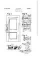
- Figure 2 is a vertical section showing the gears and dials through which the lock is operated.
- Figure 3 is a cross section showing one of the gears with the contact points on the sides thereof.
- Figure 4 is a diagrammatic View showing the circuit through the gears.
- Figure 5 is a detail showing the solenoid.
- the dials 1 are mounted upon pins 4 in a casing 5 as shown in Figure 1 and may be provided with knobs 6 by which they may be rotated.
- the casing 5 may be mounted on a door frame, as shown, and. may be provided with a cover '7 which is mounted upon the casing by hinges 8 and held by a latch 9.
- a casing is shown in Figure 1, it will be understood that this casing may be omitted and the dials mounted directly upon a plate 10 as shown in Figure 2.
- the pins 4 are rotatably mounted between the plate 10 anda bar 11 which may be attached to posts 12 on the plate 10' by screws 13.
- On the inner portion of the shaft 4 are worm gears 14 that mesh with and operate the large gears 2 rotatably mounted upon pins 15 in brackets 16.
- the brackets 16 are also mounted in the plate 10 at one end and in thebar 11 at the other.
- the gears 2 are preferably made of a nonconducting material, and pins 1'7 which are made'of, a conducting material are placed through the gears. These pins engage contact points 18 and 19 which bear against bothsides of theigears, as shown in Figure 3, and are arranged so that as the gears are set with the pins 1'7v engaging the points 18 a circuit may be completed through the points. These points may be connected in any suitable manner to any suitable source of electric current.
- one wire of the circuit which is indicated by the numeral 20, extends through the device, and the other wire, which is indicated by the numeral 21, is connected by a wire 22 to one of the contact points, as shown.
- the other contact point on the opposite side of thegear is connected by a wire 23 to one of the contact points engaging the next gear, and then the contact point on the opposite side of the said next gear is connected by wires 2a to the contact point of another succeeding gear.
- wire 25 is provided with. a button switch which.
- This method of connecting the contact points is indicated by the numeral 26, and it will be observed that when the combination has been set by turning the dials so that allof the contact points engage pins extending through the gears and the button 26 is pressed, a circuit will be completed through a solenoid, which is indicated by the numeral 27.
- the opposite ends of the wires 20 and-21 maybe connected to any suitable source Y t of electric current.
- I I I The lock is also provided with another wire 28 which by-passes the dials and gears and connects directly to the solenoid in place of the wire 25 .so that thiscircuit'may be completed through the solenoid from the inside of the door without operating the dials.
- This wire is provided with a button switch 29 which is located on the inside of the door, whereas the button switch 26 is located upon the outside.
- the bolt 3 is slidably mounted in the solenoid 2'7 and the solenoid is mounted in the door frame in such a manner that as a solenoid is energized it will draw the bolt 3 into it to release the door.
- a casing 3- At the inner end of the solenoid is a casing 3-) having a spring 31 therein which engages disc 32' on a pin 33 extending from the inner end of the bolt 3. This is comparatively a light spring which holds the bolt 3 in the outward position when the solenoid is not energized.
- the lock may be. installed with the bolt in the door frame and the casing on the outside of the frame, and
- the person knowing the combination may set the gears by turning the dials until all of the contact members in the gears are engaged in the contact points, and then by pressing the button, a circuit will be completed and the lockbolt withdrawn. As soon as the button is released the solenoid will release the bolt and the combination may be upset. It will be noted that the door may be gripped by the handle as shown in Figure 1, and at the same time the thumb of the hand gripping the handle may be placed upon the button 26 so that the lock may readily be operated as the door is gripped.
- the combination may readily be changed by removing the bar 11 and slightly rotating the worms 14 while holding the gears 2 stationary. It will'be observed that by this method any one may set or resetthe combination.
- a combination device having a plurality of independently operable gears positioned one above the other, an indicating dial for each gear with the dials also positioned one above the other, separate and independent knobs for said dials, worms meshing with said gears, shafts upon which said worms and dials are mounted, a casing in which said gears and worms are mounted and inwhich the rear member of said casing is removable, permitting adjustment of the relation of said worms to said gears to change the combinations, contact members carried on said gears, contact arms positioned on said casing cooperatingwith said gear contacts, said casing adapted to be installed in a door frame adjacent thelock of saiddoor, said combination device being adapted to operate said lock when all of the gears are so positioned;
Landscapes
- Physics & Mathematics (AREA)
- General Physics & Mathematics (AREA)
- Casings For Electric Apparatus (AREA)
Description
Feb. 26, 1935. O3 PETERS N 1,992,541
GOMBI-NATION DEVICE Filed April 23, 1950 Fig. 1 Fi 2 liiiiiiilll'iill I EEEEEEEEEEE'ET1i ?iiiiliiliiiiiiiiiiiiiiiliiililiiilim!.!!!!!!.!!!!liiii! ATTO R N EY Patented Feb. 26, 1935 UNITED STATES.-
COMBINATION DEVICE Oscar Peterson, Seattle, Wash.
Application April 23, 1930, Serial No. 446,432
' 1 Claim.
v The invention is a combination device for operating electro-magnetic door locks, in which a plurality of gears and dials are so arranged that the combination may be readily changed.
The object of the invention is to provide a combination device for operating electro-magnetic locks which is adaptable for a home, oilice or any other use.
Another object of the invention is to provide a combination device for operating electro-mag netic locks in which the combination may readily be changed.
- A further object of the invention is to provide a combination device for. operating electro-mag- .netic locks which may readily be installed.
A still further object of the invention is to provide a combination device for operating locks which is formed with units that may readily be added or subtracted to increase or decrease the number of combinations obtainable.
And a still further object of the invention is to provide a combination device for operating locks which are of a simple and economical construction.
With these ends in view the invention embodies a bolt slidable in a solenoid in combination with a plurality of dials which are connected to gears having contact members extending through the gears and engaging contact points at the sides of the gears.
Other features and advantages of the invention will appear from the following description taken in connection with the drawing, wherein:
Figure 1 is a view showing a door with the lock mounted in the frame and part of a lock casing broken away.
Figure 2 is a vertical section showing the gears and dials through which the lock is operated.
Figure 3 is a cross section showing one of the gears with the contact points on the sides thereof.
Figure 4 is a diagrammatic View showing the circuit through the gears.
Figure 5 is a detail showing the solenoid.
In the drawing the lock is formed as it would be made wherein numeral 1 indicates the dials, numeral 2 the gears, and numeral 3' the lock bolt.
The dials 1 are mounted upon pins 4 in a casing 5 as shown in Figure 1 and may be provided with knobs 6 by which they may be rotated. The casing 5 may be mounted on a door frame, as shown, and. may be provided with a cover '7 which is mounted upon the casing by hinges 8 and held by a latch 9. Although a casing is shown in Figure 1, it will be understood that this casing may be omitted and the dials mounted directly upon a plate 10 as shown in Figure 2. The pins 4 are rotatably mounted between the plate 10 anda bar 11 which may be attached to posts 12 on the plate 10' by screws 13. On the inner portion of the shaft 4 are worm gears 14 that mesh with and operate the large gears 2 rotatably mounted upon pins 15 in brackets 16. The brackets 16 are also mounted in the plate 10 at one end and in thebar 11 at the other. The gears 2 are preferably made of a nonconducting material, and pins 1'7 which are made'of, a conducting material are placed through the gears. These pins engage contact points 18 and 19 which bear against bothsides of theigears, as shown in Figure 3, and are arranged so that as the gears are set with the pins 1'7v engaging the points 18 a circuit may be completed through the points. These points may be connected in any suitable manner to any suitable source of electric current.
In the view shown in Figure 4 one wire of the circuit, which is indicated by the numeral 20, extends through the device, and the other wire, which is indicated by the numeral 21, is connected by a wire 22 to one of the contact points, as shown. The other contact point on the opposite side of thegear is connected by a wire 23 to one of the contact points engaging the next gear, and then the contact point on the opposite side of the said next gear is connected by wires 2a to the contact point of another succeeding gear.
may be continued through as many gears as may be desired. A portion of the wire which is connected to the contact point of the last'gear in use, which is indicated by the numeral 25, is connected to one end of a solenoid while the other wire 20 is connected to the opposite end. The
This method of connecting the contact points is indicated by the numeral 26, and it will be observed that when the combination has been set by turning the dials so that allof the contact points engage pins extending through the gears and the button 26 is pressed, a circuit will be completed through a solenoid, which is indicated by the numeral 27. The opposite ends of the wires 20 and-21 maybe connected to any suitable source Y t of electric current. I I I The lock is also provided with another wire 28 which by-passes the dials and gears and connects directly to the solenoid in place of the wire 25 .so that thiscircuit'may be completed through the solenoid from the inside of the door without operating the dials. This wire is provided with a button switch 29 which is located on the inside of the door, whereas the button switch 26 is located upon the outside.
The bolt 3 is slidably mounted in the solenoid 2'7 and the solenoid is mounted in the door frame in such a manner that as a solenoid is energized it will draw the bolt 3 into it to release the door. At the inner end of the solenoid is a casing 3-) having a spring 31 therein which engages disc 32' on a pin 33 extending from the inner end of the bolt 3. This is comparatively a light spring which holds the bolt 3 in the outward position when the solenoid is not energized.
It will be understood that other changes may be made in the construction Without-departing from the spirit of the invention. One of which changes may be in the design and arrangement of the gears, another may be in the-design or arrangement of the dials or in the use of other means for operating the same, and still another may be in the use of this combination of dials and'gears for operating a lock of any other description.
The construction will be readily understood from the foregoing description. In use the lock may be. installed with the bolt in the door frame and the casing on the outside of the frame, and
when it is desired to open the door the person knowing the combination may set the gears by turning the dials until all of the contact members in the gears are engaged in the contact points, and then by pressing the button, a circuit will be completed and the lockbolt withdrawn. As soon as the button is released the solenoid will release the bolt and the combination may be upset. It will be noted that the door may be gripped by the handle as shown in Figure 1, and at the same time the thumb of the hand gripping the handle may be placed upon the button 26 so that the lock may readily be operated as the door is gripped.
The combination may readily be changed by removing the bar 11 and slightly rotating the worms 14 while holding the gears 2 stationary. It will'be observed that by this method any one may set or resetthe combination.
Having thus fully described the invention that I claim as new and desire to secure by Letters Patent, is:
a As anarticle of manufacture, a combination device having a plurality of independently operable gears positioned one above the other, an indicating dial for each gear with the dials also positioned one above the other, separate and independent knobs for said dials, worms meshing with said gears, shafts upon which said worms and dials are mounted, a casing in which said gears and worms are mounted and inwhich the rear member of said casing is removable, permitting adjustment of the relation of said worms to said gears to change the combinations, contact members carried on said gears, contact arms positioned on said casing cooperatingwith said gear contacts, said casing adapted to be installed in a door frame adjacent thelock of saiddoor, said combination device being adapted to operate said lock when all of the gears are so positioned;
that their respective contactors are in contact with their respective fixed contactors.
OSCAR PETERSON.
Priority Applications (1)
| Application Number | Priority Date | Filing Date | Title |
|---|---|---|---|
| US446432A US1992541A (en) | 1930-04-23 | 1930-04-23 | Combination device |
Applications Claiming Priority (1)
| Application Number | Priority Date | Filing Date | Title |
|---|---|---|---|
| US446432A US1992541A (en) | 1930-04-23 | 1930-04-23 | Combination device |
Publications (1)
| Publication Number | Publication Date |
|---|---|
| US1992541A true US1992541A (en) | 1935-02-26 |
Family
ID=23772555
Family Applications (1)
| Application Number | Title | Priority Date | Filing Date |
|---|---|---|---|
| US446432A Expired - Lifetime US1992541A (en) | 1930-04-23 | 1930-04-23 | Combination device |
Country Status (1)
| Country | Link |
|---|---|
| US (1) | US1992541A (en) |
Cited By (6)
| Publication number | Priority date | Publication date | Assignee | Title |
|---|---|---|---|---|
| US2637578A (en) * | 1951-05-28 | 1953-05-05 | Rafael C Gaona | Electrically controlled lock |
| US3242708A (en) * | 1961-11-27 | 1966-03-29 | Clavex S A | System of remote-control keyless automatic electric locks |
| US3468143A (en) * | 1966-10-21 | 1969-09-23 | Bambino Electronics Ltd | Random selection electrical combination locks |
| US3722238A (en) * | 1971-07-29 | 1973-03-27 | A Ring | Remotely operated electrical combination lock |
| DE2825783C3 (en) * | 1978-06-13 | 1982-02-18 | Paul Rudolf 8203 Oberaudorf Moritz | Electric lock |
| DE10038867B4 (en) * | 2000-08-04 | 2014-07-17 | Geze Gmbh | Door system with locking device |
-
1930
- 1930-04-23 US US446432A patent/US1992541A/en not_active Expired - Lifetime
Cited By (6)
| Publication number | Priority date | Publication date | Assignee | Title |
|---|---|---|---|---|
| US2637578A (en) * | 1951-05-28 | 1953-05-05 | Rafael C Gaona | Electrically controlled lock |
| US3242708A (en) * | 1961-11-27 | 1966-03-29 | Clavex S A | System of remote-control keyless automatic electric locks |
| US3468143A (en) * | 1966-10-21 | 1969-09-23 | Bambino Electronics Ltd | Random selection electrical combination locks |
| US3722238A (en) * | 1971-07-29 | 1973-03-27 | A Ring | Remotely operated electrical combination lock |
| DE2825783C3 (en) * | 1978-06-13 | 1982-02-18 | Paul Rudolf 8203 Oberaudorf Moritz | Electric lock |
| DE10038867B4 (en) * | 2000-08-04 | 2014-07-17 | Geze Gmbh | Door system with locking device |
Similar Documents
| Publication | Publication Date | Title |
|---|---|---|
| US1992541A (en) | Combination device | |
| US3559430A (en) | Locking mechanism | |
| DE538812C (en) | Door lock | |
| DE661352C (en) | Self-lending for objects of use with deposit | |
| US1433543A (en) | Electrical combination lock | |
| US2909711A (en) | Electric lock mechanism | |
| US2136584A (en) | Combination lock | |
| US3306536A (en) | Multiple totalizer | |
| US1573802A (en) | Electric safety combination lock | |
| US2172709A (en) | Lighter | |
| DE319876C (en) | Device for unlocking a door lock by electrical means | |
| DE327769C (en) | Electric front door lock | |
| DE370427C (en) | Electric security lock | |
| DE811970C (en) | Electric door switch | |
| US1586471A (en) | Lock | |
| DE102018000767A1 (en) | Security management for safes and valuables cabinets in professional banking and private sector | |
| DE379667C (en) | Push-button circuit for electrically driven rotary printing machines or similar machines with a lock caused by a switching point | |
| DE348742C (en) | Combination switch for electric locks | |
| DE335936C (en) | Electric noise device for locks | |
| US2153903A (en) | Automobile theft alarm and ignition lock | |
| DE335636C (en) | Electric lock security | |
| US1811563A (en) | Combination lock | |
| DE275027C (en) | ||
| US1381021A (en) | Electric-switch lock | |
| DE445960C (en) | Closure for cellar windows, doors, trap doors or the like. |