US1965229A - Drier and the like - Google Patents
Drier and the like Download PDFInfo
- Publication number
- US1965229A US1965229A US492146A US49214630A US1965229A US 1965229 A US1965229 A US 1965229A US 492146 A US492146 A US 492146A US 49214630 A US49214630 A US 49214630A US 1965229 A US1965229 A US 1965229A
- Authority
- US
- United States
- Prior art keywords
- chamber
- fan
- air
- conveyor
- contact chamber
- Prior art date
- Legal status (The legal status is an assumption and is not a legal conclusion. Google has not performed a legal analysis and makes no representation as to the accuracy of the status listed.)
- Expired - Lifetime
Links
Images


Classifications
-
- F—MECHANICAL ENGINEERING; LIGHTING; HEATING; WEAPONS; BLASTING
- F26—DRYING
- F26B—DRYING SOLID MATERIALS OR OBJECTS BY REMOVING LIQUID THEREFROM
- F26B17/00—Machines or apparatus for drying materials in loose, plastic, or fluidised form, e.g. granules, staple fibres, with progressive movement
- F26B17/02—Machines or apparatus for drying materials in loose, plastic, or fluidised form, e.g. granules, staple fibres, with progressive movement with movement performed by belts carrying the materials; with movement performed by belts or elements attached to endless belts or chains propelling the materials over stationary surfaces
- F26B17/04—Machines or apparatus for drying materials in loose, plastic, or fluidised form, e.g. granules, staple fibres, with progressive movement with movement performed by belts carrying the materials; with movement performed by belts or elements attached to endless belts or chains propelling the materials over stationary surfaces the belts being all horizontal or slightly inclined
Definitions
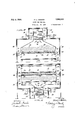
- Fig. I shows a vertical crosssection through one form of drier conveniently embodying my invention.
- Figs. II, 111, IV, V and VI are similar views illustrating modifications.
- Fig. VII is a plan view, with the top portion of the outside drierhousing broken away and removed, taken as indicated by the line and arrows VIP-VII in Fig. VI.
- Fig. V'IlI shows a vertical section, through the upper portion of the drier, taken as indicated by the line and arrows VIIIVIII in Fig. VII.
- Figs. IX and X are views similar to Figs. V and VI, showing other modifications.
- the drier here shown has a contact or drying chamber 10 in which the material A under treatment is supported by suitable means, shown as a conveyor 11 of spaced transverse bars supporting a wire cloth apron 11a.
- suitable means shown as a conveyor 11 of spaced transverse bars supporting a wire cloth apron 11a.
- a centrifugal multi-vane fan 13 shown to best advantage in Fig. VIII, which receives air axially through an intake opening 14 in the casing wall 15 at one side of the chamber 10 and discharges the air peripherally.
- These multi-vane fans 13 are preferably those known in the art as cycloidal fans, in that they are adapted to deliver a positive flow of air, without any tendency towards spiral or whirling action of the air current.
- the discharge from thefan 13 goes directly down into the main portion of the chamber 10, on the material A therein.
- inclined deflecting means 16 that helps to distribute the air across the width of the chamber 10, and may be adjustable to control and regulate the air distribution.
- the closeness of the material A to the fan 13 gives the very best penetration thereof by the air. Passing through the material A, the air leaves the chamber 10 through an outlet opening or gap 1'! in the wall-15.
- the drier is enclosed in an external housing 18 that forms a return chamber or passage 19 beside the wall 15, connecting the openings 14 and 17.
- the fan compartment or casing 12 is much narrower than the chamber 10, and the casing wall 15 is the two opposite sides of the apparatus, so that there are similar return passages 19 in the enclosure 18 at opposite sides of a central contact chamber 10,-giving a balanced air circulation,
- the enclosure 18 has a narrowed lateral monitor-like extension or turret 20 at its upper side, opening downward into its mid region, with the fan compartment 12 in the midst of this extension 20.
- a centrifugal fan 13 of double inlet type, receiving air axially from both sides.
- the fan shaft 20a extends out through the walls 18 at either side of the extension 20, where its bearings 21 are located, as Well as its driving means, shown as pulleys 22, for driving belts (not shown). Thus the bearings 21 and the driving means22 are not exposed to the heat in the drier.
- the parts 21, 22 lie withinthe overall width of the housing 18, in the space afforded by the narrowness of the extension 20, so that they do not increase the floor space occupied. Because of the central location of the fan 13, greater uniformity of air circulation is achieved in this double drier than with-a single circulation type.
- the conveyor 11 has rollers 23 that run on rails 24 mounted on the inner casing walls or partitions 15. At either side of the conveyor 11 is an upright guard 25 that confines the material A and excludes it from the rollers 23 and rail 24.
- the upper edge of the guard 25 travels quite close to an inward extending portion or shoulder 26 of the wall 15, so as to prevent air leakage around the edges of the conveyor 11. .
- the lower return run of the conveyor 11 travels upside down below the openings 17.
- a heater 30 for the air is shown in the chamber 10, beneath the conveyor 11 but above the openings 17.
- This heater 30 comprises pipes or coils 31 extending lengthwise of the conveyor 11, and distributed across the width of chamber 10 and conveyor 11, so as to heat the air uniformly.
- the streams of heated air issuing beneath the pipes 31 are thoroughly mixed in making the 90 turn to right and left to the openings 17, as well as in the crooked passages 19 and in the fan 13, so that a very uniform heat is applied to the material A.
- Fig. II there are two heaters 30, one in each of the passages 19.
- the vertical walls 15-at opposite sides of the chamber 10 are prolonged upward at 32 above the sloping portions of said walls, to assure contact of the returning air with all of the heating pipes 31.
- the heater 30 is like that of Fig. I, but located above the conveyor 11 instead of below it. Accordingly, sloping aprons 33 extend inward from the partition walls 15 close over the upper edges of the conveyor guards 25 for the same purpose as the shoulders-26 in Fig. I.
- Fig. IV shows an inversion of the general arrangement illustrated in Figs. I, II and 111: i. e., the narrowed extension 20 of the enclosure 18, the fan compartment 12, and the fan 13 are at the bottom, and said fan 13 discharges air upward into the chamber 10 against the material A on the conveyor 11. however: i. e., its upper run is still the loaded one, and its lower run the idle return run.
- a screen or grid 35 is provided over the material A, in the form of an openwork conveyor similar to the conveyor 11 and travelling at the same linear speed, and located just below the openings 1'7, so as to prevent the material A from blowing out through the openings 1'7 into the chambers 19.
- This conveyor 35 travels on tracks 36 mounted on the irmer sides of the partitions 15 with its active lower run just below the openings 17, and its return run just above them. While the heater 30 might, of course, be variously located, as indicated in Figs. I-III, in the present instance it is shown below the material A, between the upper and lower runs of the conveyor 11.
- a machine of cross-sectional arrangement such as shown in Figs. I-IV may comprise any number of units, each with its fan or fans 13.
- the drier can be built single instead of double, with either a single or a double fan, and with a straight vertical wall at one side, corresponding in location to the vertical center-line of the double drier. This, of course, gives only a single return passage,
- Fig. V shows a single er resembling the double-drier of Fig. 111, with a single centrifugal fan 13 over the left-hand side of the contact chamber 10 and the material A, and a single return passage 19 leading directly to the single inlet 14 of the fan compartment or casing 12.
- Deflectors 16a directly belowthe fan 13 are both inclined toward the right, so as to throw much of the air stream toward that side of the chamber 10 and make the circulation through the material A as uniform as possible.
- Fig. VI shows a single drier like that of Fig.
- the conveyor 11 is not inverted
- Fig. VII affords a fragmentary plan view (with a partof the outer housing 18 in section) of a length of drier including two fans 13 and casing 12, showing how the air from the return passage 19 reaches the inlets 14 at the far side of the fans (Fig. VI); and Fig. VIII is a corresponding sectional view, taken as indicated by the line and arrows VIII-VIII in Fig.
- Fig. IX shows a single drier with its return passage 19a at the same side. of the contact chamber 10 as the single-inlet centrifugal fan 13, instead of at the other side, as in Figs. V and VI.
- Fig. X shows a single drier like that of Fig.
- the return chamber or passage 19 extends along at least two adjacent, vertical and horizontal sides of the contact chamber 10.
- the fan casing or compartment 12, as shown in Figs. VII and VIII, which essentially represent the construction in all cases where a double fan is used, is located in a horizontal portion. of this passage 19, while the vertical portion (or portions) of this passage 19 communicates with the chamber 10 at a point remote from the fan discharge into said chamber.
- the passage 19 extends around three adjacent sides of the chamber 10; and this is also essentially true of Figs. IX and X, since the space below the battle 37 may be regarded as a horizontal extension of the return passage 19 beneath the contact chamber 10 proper, and the opening at the end of the battle 37 as the contact chamber outlet into this horizontal portion of the passage 19.
- an enclosure partitioning dividing the interior of said enclosure into a contact chamber, setting apart a narrower fan compartment, and also a return passage flanking both the chamber and the fan compartment with communication thereinto by relatively remote openings; heater means coextensive with and proximate the conveyor; a centrifugal multi-vane fan in the compartment aforesaid receiving air axially from the return passage and discharging it peripherally into the contact chamber only; and deflecting means at the fan outlet for difiusing the discharging air means coextensive with and closely proximate the full extent of one flight of the conveyor; a centrifugal multi-vane fan in the compartment aforesaid receiving air axially from the return passage and discharging it peripherally into the contact chamber only; and adjustable deflecting means at the fan outlet for diffusing the dis charging air directly onto and evenly across the material of the conveyor.
- an enclosure and partition means dividing the same into a contact chamber and a return chamber, the latter communicating with the former at separated points, means for progressively supporting material to be treated in the contact chamber between said points, heater means extending lengthwise of and across the width of the progressing means, and a centrifugal multi-vane fan in said contact chamber receiving air from the return chamber axially, and discharging said air peripherally for divergent diffusion directly onto the material.
- diireringly directed deflectors effective to diffuse the air diagonally across the chamber to said outlet opening and thus act substantially uniformly on the material over the width of the chamber.
- an enclosure and partition means dividing the same into a contact chamber and a return passage extending vertically and horizontally along two adjacent sides of said chamber, a fan casing with a lateral intake opening into the vertical portion of said passage, a centrifugal fan in said casing receiving air axially through-said opening and discharging the air peripherally directly into one side of said contact chamber, said contact chamber communicating with the horizontal portion of said passage at the opposite side from said fan, conveyor means for supporting material to be treated in said contact chamber between the fan discharge and the point of communication between the contact chamber and passage; and heater means extending lengthwise of and adjacently paralleling .the full width of the conveyor means.
- an enclosure and partition means dividing the same into a contact chamber and a return passage extending vertically and horizontally along adjacent sides of said chamber, a fan casing in the horizontal part of .said passage with intake openings in either side, a double centrifugal fan in said casing receiving air axially through said intake openings and discharging the air peripherally directly into said contact chamber, said contact chamber communicating with the vertical portion of said passage, conveyor means for supporting material to be treated in said contact chamber between the fan discharge and the point of communication between the contact chamber'and passage; and heater means extending longitudinally of and adjacently above the full width of the conveyor means.
- heater means for supporting material to be treated in said contact chamber between the fan discharge and the point of communication between the contact chamber and passage; and heater means extending longitudinally of and proximately above the full width of the conveyor means.
- anenclosure and partition means dividing the same into a contact chamber and a return passage extending vertically and horizontally along two adjacent sides of said chamber, a fan casing in one horizontal part of said passage with intake openings in either side, a double centrifugal fan in said casing receiving air axially through said intake openings and discharging the air peripherally directly into one side of said contact chamber, said contact chamber communicating with the other horizontal portion of said passage at the opposite side of said chamber from said fan, conveyor means for supporting material to be treated in said contact chamber between. the fan discharge'and the point of communication between the contact chamber and passage, and heater means extending longitudinally of and adjacently above the full width of the conveyor means.
Landscapes
- Engineering & Computer Science (AREA)
- Mechanical Engineering (AREA)
- General Engineering & Computer Science (AREA)
- Drying Of Solid Materials (AREA)
Description
July 3, 1934. H. L. GALSON DRIER AND THE LIKE Filed 001;. so. 1930 4 Sheets-Sheet 1 OOOOOOOOOOOO OOOOOOO INVENTOR. Jznryfi'alsmz,
WITNESSES A A TTORNEY.
July 3, 1934. H. GALSON DRIER AND THE LIKE 4 Sheets-Sheet 2 Filed Oct. 30. 1930 I N VEN TOR. Jinr LG'WZSon,
WITNESSE w j/w /w A TTORNEY.
y 1934. H. GALSON I 1,965,229
DRIER AND THE LIKE Filed Oct. 50. 19:50 4 Sheets-Sheet 4 18 ""15 HG K.
15 k 3b ,18 HC-kll 20 22 Z i000000000oooo oooooooooooooooooooo 18 s0000000000OOOQOOOOO OOOOOOOOOOOOO 19a OOOOOOOOQ0000OOOOOOOOOOOOOOOOOOOQ 7'. /25
2% g I /?Q INVENTOR.
fzimryl. Galsm TORNEY.
?atented July 3, 1934 STAT-ES PATENT OFFICE 1,965,229 DRIER AND THELIKE -Henry L. Galson, Philadelphia, Pa., asslgnor to The Philadelphia Drying Machinery Company, Philadelphia, Pa., a corporation of Pennsylvania My invention relates to driers and the like, and is largely concerned with arrangements and provisions for the air circulation. or movement. Various advantages that can be realized through the invention will be apparent to those skilled in the art from my description hereinafter of selected and preferred embodiments,said advantages including rapid circulation, thorough contact of the air with the material under treatment, and compactness of the apparatus proportion to its drying capacity. The particular embodiments here illustrated are especially adapted for use in the textile industry, for drying fibrous materials or raw stock, though not limited to this particular use.
In the drawings, Fig. I showsa vertical crosssection through one form of drier conveniently embodying my invention.
Figs. II, 111, IV, V and VI are similar views illustrating modifications.
Fig. VII is a plan view, with the top portion of the outside drierhousing broken away and removed, taken as indicated by the line and arrows VIP-VII in Fig. VI.
Fig. V'IlI shows a vertical section, through the upper portion of the drier, taken as indicated by the line and arrows VIIIVIII in Fig. VII.
Figs. IX and X are views similar to Figs. V and VI, showing other modifications.
The drier here shown has a contact or drying chamber 10 in which the material A under treatment is supported by suitable means, shown as a conveyor 11 of spaced transverse bars supporting a wire cloth apron 11a. In a compartment 12 of the chamber 10 is a centrifugal multi-vane fan 13, shown to best advantage in Fig. VIII, which receives air axially through an intake opening 14 in the casing wall 15 at one side of the chamber 10 and discharges the air peripherally. These multi-vane fans 13 are preferably those known in the art as cycloidal fans, in that they are adapted to deliver a positive flow of air, without any tendency towards spiral or whirling action of the air current. The discharge from thefan 13 goes directly down into the main portion of the chamber 10, on the material A therein. Between the fan 13 and the material A is shown inclined deflecting means 16, that helps to distribute the air across the width of the chamber 10, and may be adjustable to control and regulate the air distribution. The closeness of the material A to the fan 13 gives the very best penetration thereof by the air. Passing through the material A, the air leaves the chamber 10 through an outlet opening or gap 1'! in the wall-15. As here shown, the drier is enclosed in an external housing 18 that forms a return chamber or passage 19 beside the wall 15, connecting the openings 14 and 17. The fan compartment or casing 12 is much narrower than the chamber 10, and the casing wall 15 is the two opposite sides of the apparatus, so that there are similar return passages 19 in the enclosure 18 at opposite sides of a central contact chamber 10,-giving a balanced air circulation,
and the enclosure 18 has a narrowed lateral monitor-like extension or turret 20 at its upper side, opening downward into its mid region, with the fan compartment 12 in the midst of this extension 20. Instead of two single-inlet centrifugal fans 13 side by side in the compartment 12, -I have shown one centrifugal fan 13 of double inlet type, receiving air axially from both sides. The fan shaft 20a extends out through the walls 18 at either side of the extension 20, where its bearings 21 are located, as Well as its driving means, shown as pulleys 22, for driving belts (not shown). Thus the bearings 21 and the driving means22 are not exposed to the heat in the drier. However, the parts 21, 22 lie withinthe overall width of the housing 18, in the space afforded by the narrowness of the extension 20, so that they do not increase the floor space occupied. Because of the central location of the fan 13, greater uniformity of air circulation is achieved in this double drier than with-a single circulation type.
As shown in Fig. I, the conveyor 11 has rollers 23 that run on rails 24 mounted on the inner casing walls or partitions 15. At either side of the conveyor 11 is an upright guard 25 that confines the material A and excludes it from the rollers 23 and rail 24. In the case of the loaded upper run of the conveyor 11, the upper edge of the guard 25 travels quite close to an inward extending portion or shoulder 26 of the wall 15, so as to prevent air leakage around the edges of the conveyor 11. .The lower return run of the conveyor 11 travels upside down below the openings 17.
In Fig. I, a heater 30 for the air is shown in the chamber 10, beneath the conveyor 11 but above the openings 17. This heater 30 comprises pipes or coils 31 extending lengthwise of the conveyor 11, and distributed across the width of chamber 10 and conveyor 11, so as to heat the air uniformly. The streams of heated air issuing beneath the pipes 31 are thoroughly mixed in making the 90 turn to right and left to the openings 17, as well as in the crooked passages 19 and in the fan 13, so that a very uniform heat is applied to the material A. I
In Fig. II, there are two heaters 30, one in each of the passages 19. Here the vertical walls 15-at opposite sides of the chamber 10 are prolonged upward at 32 above the sloping portions of said walls, to assure contact of the returning air with all of the heating pipes 31.
In Fig. III, the heater 30 is like that of Fig. I, but located above the conveyor 11 instead of below it. Accordingly, sloping aprons 33 extend inward from the partition walls 15 close over the upper edges of the conveyor guards 25 for the same purpose as the shoulders-26 in Fig. I.
Fig. IV shows an inversion of the general arrangement illustrated in Figs. I, II and 111: i. e., the narrowed extension 20 of the enclosure 18, the fan compartment 12, and the fan 13 are at the bottom, and said fan 13 discharges air upward into the chamber 10 against the material A on the conveyor 11. however: i. e., its upper run is still the loaded one, and its lower run the idle return run. As the air blows up through the conveyor 11 and the material A resting thereon, a screen or grid 35 is provided over the material A, in the form of an openwork conveyor similar to the conveyor 11 and travelling at the same linear speed, and located just below the openings 1'7, so as to prevent the material A from blowing out through the openings 1'7 into the chambers 19. This conveyor 35 travels on tracks 36 mounted on the irmer sides of the partitions 15 with its active lower run just below the openings 17, and its return run just above them. While the heater 30 might, of course, be variously located, as indicated in Figs. I-III, in the present instance it is shown below the material A, between the upper and lower runs of the conveyor 11.
A machine of cross-sectional arrangement such as shown in Figs. I-IV may comprise any number of units, each with its fan or fans 13. Also, the drier can be built single instead of double, with either a single or a double fan, and with a straight vertical wall at one side, corresponding in location to the vertical center-line of the double drier. This, of course, gives only a single return passage,
- at one side of the drier, and an unsymmetrical I location of the fan 13, over one side of the material A, and hence not, perhaps, so uniform a circulation of air as the double drier. Various constructions of this character are shown in Figs. V-X. Except as hereinafter described, these constructions are substantially like those already described (more especially that of Fig-I11), and are marked with thesame reference characters, in order to avoid repetitive description.
Fig. V shows a single er resembling the double-drier of Fig. 111, with a single centrifugal fan 13 over the left-hand side of the contact chamber 10 and the material A, and a single return passage 19 leading directly to the single inlet 14 of the fan compartment or casing 12. Deflectors 16a directly belowthe fan 13 are both inclined toward the right, so as to throw much of the air stream toward that side of the chamber 10 and make the circulation through the material A as uniform as possible.
Fig. VI shows a single drier like that of Fig.
The conveyor 11 is not inverted,
V, but having a double centrifugal fan 13 with its compartment or casing 12 spaced from the outer casing wall 18 to aiiford inlets 14 from both sides of the fan. Fig. VII affords a fragmentary plan view (with a partof the outer housing 18 in section) of a length of drier including two fans 13 and casing 12, showing how the air from the return passage 19 reaches the inlets 14 at the far side of the fans (Fig. VI); and Fig. VIII is a corresponding sectional view, taken as indicated by the line and arrows VIII-VIII in Fig.
VII.
Fig. IX shows a single drier with its return passage 19a at the same side. of the contact chamber 10 as the single-inlet centrifugal fan 13, instead of at the other side, as in Figs. V and VI. As here shown, there is a sloping baflie 37 extending from the upper edge of the opening 17 toward the other side of the chamber 10, so as to equalize the air .flow in the chamber 10 and through the material A.
Fig. X shows a single drier like that of Fig.
IX, but with a double fan 13 instead of a single one.
It will be understood that in all the forms illustrated, the return chamber or passage 19 extends along at least two adjacent, vertical and horizontal sides of the contact chamber 10. The fan casing or compartment 12, as shown in Figs. VII and VIII, which essentially represent the construction in all cases where a double fan is used, is located in a horizontal portion. of this passage 19, while the vertical portion (or portions) of this passage 19 communicates with the chamber 10 at a point remote from the fan discharge into said chamber. Thus'the air must in all cases traverse the chamber 10 diagonally, assuring its more uniform action on the material A over the whole'width of the chamber 10. In Figs. I-IV, the passage 19 extends around three adjacent sides of the chamber 10; and this is also essentially true of Figs. IX and X, since the space below the battle 37 may be regarded as a horizontal extension of the return passage 19 beneath the contact chamber 10 proper, and the opening at the end of the battle 37 as the contact chamber outlet into this horizontal portion of the passage 19.
Having thus described my invention, I claim:
1. In apparatus of the character described, an enclosure, partitioning dividing the interior of said enclosure into a contact chamber, setting apart a narrower fan compartment, and also a return passage flanking both the chamber and the fan compartment with communication thereinto by relatively remote openings; heater means coextensive with and proximate the conveyor; a centrifugal multi-vane fan in the compartment aforesaid receiving air axially from the return passage and discharging it peripherally into the contact chamber only; and deflecting means at the fan outlet for difiusing the discharging air means coextensive with and closely proximate the full extent of one flight of the conveyor; a centrifugal multi-vane fan in the compartment aforesaid receiving air axially from the return passage and discharging it peripherally into the contact chamber only; and adjustable deflecting means at the fan outlet for diffusing the dis charging air directly onto and evenly across the material of the conveyor.
3. In apparatus of the character described the combination of an enclosure and partition means dividing the same into a contact chamber and a return chamber, the latter communicating with the former at separated points, means for progressively supporting material to be treated in the contact chamber between said points, heater means extending lengthwise of and across the width of the progressing means, and a centrifugal multi-vane fan in said contact chamber receiving air from the return chamber axially, and discharging said air peripherally for divergent diffusion directly onto the material.
4. The combination, in an apparatus of the character described, of an enclosure containing a contact chamber with a narrowed fan com partment, there being an air intake opening in the fan compartment wall and an air outlet from said compartment into the contact chamber; means for progressively supporting material to be treated in the contact chamber between said openings; heater means extending lengthwise of and across the full width of the progressing means, a centrifugal multi-vane fan in said narrow compartment receiving air axially through the intake opening, and discharging the air peripherally by way of the outlet opening aforesaid directly into the contact chamber; and in clined deflectors in said chamber for divergently distributing the air from the fan across the full width of the contact chamber.
5. The combination, in an apparatus of the character described, of an enclosure containing a wide contact chamber and a narrowed fan compartment opening into the mid region of said chamber, there being air intake openings in the opposite sides of said compartment and an outlet therefrom into the contact chamber; conveyor means for supporting material to be treated in said contact chamber between said openings; heater means extending lengthwise of and across the full width of the conveyor means and centrifugal multi-vane fan means'in said compartment receiving air axially from both sides through said intake openings and discharging the air peripherally for divergent diffusion directly into and evenly across the contact chamber.
6. The combination, in an apparatus of the character described, of an enclosure containing a wide contact chamber and a narrowed fan compartment opening into the mid region of said chamber, there being air intake openings in the opposite sides of said compartment and an outlet therefrom into the contact chamber; conveyor dividing its interior into a central contact cham-. ber having a narrowed fan compartment opening into its mid region, with air return passages at either side of said contact chamber and com-,
compartment receiving air axially from each of said return chambers and discharging said air peripherally for divergent diffusion directly into and evenly across the contact chamber.
8. In apparatus of the character described the combination of an enclosure with a narrowed turret opening into its mid region; partition means dividing the interior of the enclosure into a central contact chamber with a narrowed fan compartment in the midst of said turret and return passages at either side of said chamber and turret, each passage communicating with said chamber and the fan compartment through an opening in the corresponding partition; conveyor means for supporting material to be treated in said chamber between said openings; heater means extending lengthwise of and adjacently across the full width of the conveyor means, centrifugal multi-vane fan means in said compartment receiving air axially at either sidev from 'said passages and discharging the air peripherally for divergent diffusion directly into and evenly across said chamber; and fan shaft bearings at the exterior of the turret on either side.
9. In apparatus of the character described the combination of an enclosure with a narrowed turret opening into the top thereof; partition means dividing the interior of the enclosure into a contact chamber with a narrowed fan compartment in said turret and a return passage extending vertically upward beside said chamber directly to said fan compartment, said passage communicating with said chamber and fan compartment through openings in said partition; a baflie extending from said partition above the opening from the chamber into said passage toward the opposite chamber wall; conveyor means for supporting material to be treated in said chamber between said openings; heater means extending lengthwise of and adjacently across the full width of the conveyor means and a centrifugal fan in said compartment'receiving air axially through the corresponding partition opening and discharging the air peripherally'for divergent diffusion directly into and evenly across said chamber.
10. The combination, in an apparatus of the character described, of a casing containing a contact chamber with a narrowed fan compartment, there being an air intake opening in the fancompartment wall and an air outlet therefrom into the contactlchamber wall at a point remote from said intake opening of the fan compartment; conveyor means for supporting material to be treated in the contact chamber between said inlet and outlet openings; heater means extending lengthwise offiand adjacently across the full width of the conveyor/means, a centrifugal fan in said compartment receiving air axially through said intake opening and discharging the air fieripherally through the outlet aforesaid directly into the contact chamber, and
diireringly directed deflectors effective to diffuse the air diagonally across the chamber to said outlet opening and thus act substantially uniformly on the material over the width of the chamber. 7
11. In apparatus of the character described the combination of an enclosure and partition means dividing the same into a contact chamber and a return passage extending vertically and horizontally along two adjacent sides of said chamber, a fan casing with a lateral intake opening into the vertical portion of said passage, a centrifugal fan in said casing receiving air axially through-said opening and discharging the air peripherally directly into one side of said contact chamber, said contact chamber communicating with the horizontal portion of said passage at the opposite side from said fan, conveyor means for supporting material to be treated in said contact chamber between the fan discharge and the point of communication between the contact chamber and passage; and heater means extending lengthwise of and adjacently paralleling .the full width of the conveyor means.
12. In apparatus of the character described the combination of an enclosure and partition means dividing the same into a contact chamber and a return passage extending vertically and horizontally along adjacent sides of said chamber, a fan casing in the horizontal part of .said passage with intake openings in either side, a double centrifugal fan in said casing receiving air axially through said intake openings and discharging the air peripherally directly into said contact chamber, said contact chamber communicating with the vertical portion of said passage, conveyor means for supporting material to be treated in said contact chamber between the fan discharge and the point of communication between the contact chamber'and passage; and heater means extending longitudinally of and adjacently above the full width of the conveyor means.
for supporting material to be treated in said contact chamber between the fan discharge and the point of communication between the contact chamber and passage; and heater means extending longitudinally of and proximately above the full width of the conveyor means.
14. In apparatus of the character described the combination of anenclosure and partition means dividing the same into a contact chamber and a return passage extending vertically and horizontally along two adjacent sides of said chamber, a fan casing in one horizontal part of said passage with intake openings in either side, a double centrifugal fan in said casing receiving air axially through said intake openings and discharging the air peripherally directly into one side of said contact chamber, said contact chamber communicating with the other horizontal portion of said passage at the opposite side of said chamber from said fan, conveyor means for supporting material to be treated in said contact chamber between. the fan discharge'and the point of communication between the contact chamber and passage, and heater means extending longitudinally of and adjacently above the full width of the conveyor means.
HENRY L. GALSON.
Priority Applications (1)
| Application Number | Priority Date | Filing Date | Title |
|---|---|---|---|
| US492146A US1965229A (en) | 1930-10-30 | 1930-10-30 | Drier and the like |
Applications Claiming Priority (1)
| Application Number | Priority Date | Filing Date | Title |
|---|---|---|---|
| US492146A US1965229A (en) | 1930-10-30 | 1930-10-30 | Drier and the like |
Publications (1)
| Publication Number | Publication Date |
|---|---|
| US1965229A true US1965229A (en) | 1934-07-03 |
Family
ID=23955129
Family Applications (1)
| Application Number | Title | Priority Date | Filing Date |
|---|---|---|---|
| US492146A Expired - Lifetime US1965229A (en) | 1930-10-30 | 1930-10-30 | Drier and the like |
Country Status (1)
| Country | Link |
|---|---|
| US (1) | US1965229A (en) |
Cited By (12)
| Publication number | Priority date | Publication date | Assignee | Title |
|---|---|---|---|---|
| US2449667A (en) * | 1946-03-14 | 1948-09-21 | Ralph C Parkes | Drying machine |
| US2471802A (en) * | 1945-11-16 | 1949-05-31 | Harold J Walter | Apparatus for heat-treating air-pervious strip material |
| US2634117A (en) * | 1950-01-28 | 1953-04-07 | Verlin A Bloxham | Apparatus for continuous drying of hops |
| US2669788A (en) * | 1950-06-07 | 1954-02-23 | Smith Drum & Company | Machine for drying hosiery |
| US2674811A (en) * | 1950-11-17 | 1954-04-13 | Us Rubber Co | Drier for porous materials |
| US2746726A (en) * | 1953-12-18 | 1956-05-22 | Clarence A Hoff | Space heater for busses and the like |
| DE1045324B (en) * | 1957-05-28 | 1958-11-27 | Schilde Maschb Ag | Tunnel dryer |
| US2920397A (en) * | 1955-06-29 | 1960-01-12 | American Viscose Corp | Method and apparatus for drying fibrous material |
| US2940239A (en) * | 1958-12-02 | 1960-06-14 | Chester J Lewandowski | Hay combine |
| DE1114148B (en) * | 1957-11-27 | 1961-09-21 | Schilde Maschb Ag | Flat track ventilation dryer |
| WO2007105941A1 (en) * | 2006-03-10 | 2007-09-20 | Edwin De Heer Aronds | Drying installation and/or method for drying an emulsion |
| RU193553U1 (en) * | 2019-06-03 | 2019-11-01 | Федеральное государственное бюджетное научное учреждение "Федеральный научный центр лубяных культур" (ФГБНУ ФНЦ ЛК) | PLANT FOR DRYING ANY RAW MATERIAL |
-
1930
- 1930-10-30 US US492146A patent/US1965229A/en not_active Expired - Lifetime
Cited By (12)
| Publication number | Priority date | Publication date | Assignee | Title |
|---|---|---|---|---|
| US2471802A (en) * | 1945-11-16 | 1949-05-31 | Harold J Walter | Apparatus for heat-treating air-pervious strip material |
| US2449667A (en) * | 1946-03-14 | 1948-09-21 | Ralph C Parkes | Drying machine |
| US2634117A (en) * | 1950-01-28 | 1953-04-07 | Verlin A Bloxham | Apparatus for continuous drying of hops |
| US2669788A (en) * | 1950-06-07 | 1954-02-23 | Smith Drum & Company | Machine for drying hosiery |
| US2674811A (en) * | 1950-11-17 | 1954-04-13 | Us Rubber Co | Drier for porous materials |
| US2746726A (en) * | 1953-12-18 | 1956-05-22 | Clarence A Hoff | Space heater for busses and the like |
| US2920397A (en) * | 1955-06-29 | 1960-01-12 | American Viscose Corp | Method and apparatus for drying fibrous material |
| DE1045324B (en) * | 1957-05-28 | 1958-11-27 | Schilde Maschb Ag | Tunnel dryer |
| DE1114148B (en) * | 1957-11-27 | 1961-09-21 | Schilde Maschb Ag | Flat track ventilation dryer |
| US2940239A (en) * | 1958-12-02 | 1960-06-14 | Chester J Lewandowski | Hay combine |
| WO2007105941A1 (en) * | 2006-03-10 | 2007-09-20 | Edwin De Heer Aronds | Drying installation and/or method for drying an emulsion |
| RU193553U1 (en) * | 2019-06-03 | 2019-11-01 | Федеральное государственное бюджетное научное учреждение "Федеральный научный центр лубяных культур" (ФГБНУ ФНЦ ЛК) | PLANT FOR DRYING ANY RAW MATERIAL |
Similar Documents
| Publication | Publication Date | Title |
|---|---|---|
| US1965229A (en) | Drier and the like | |
| US3302304A (en) | Apparatus for ventilating webs of textile material | |
| US4227317A (en) | Apparatus for the heat treatment of textiles | |
| US2083141A (en) | Apparatus for conditioning sheet material | |
| US1980558A (en) | Drying of fabrics | |
| US1534499A (en) | Drying apparatus | |
| US1995675A (en) | Drier | |
| US2101301A (en) | Method and apparatus for drying cellulose and like material in a continuous web | |
| US1778318A (en) | Drying apparatus | |
| US3362081A (en) | Cabinet dryer and method | |
| US2280704A (en) | Air circulating system for driers | |
| US2187799A (en) | Drier | |
| KR20200130728A (en) | Method and apparatus for drying plates | |
| US2152238A (en) | Material treating apparatus | |
| US3609872A (en) | Process and apparatus for the treatment of textile materials | |
| US1513932A (en) | Drier | |
| US1547294A (en) | Drying apparatus | |
| US5191725A (en) | Venting system for heat treating flat material webs | |
| US1947338A (en) | Drier | |
| US948751A (en) | Drier. | |
| US672806A (en) | Apparatus for treating tobacco. | |
| US1980163A (en) | Machine for drying textile materials | |
| US1751472A (en) | Drying process and apparatus | |
| US616293A (en) | Vidsow | |
| US2150445A (en) | Art of drying materials |