US1914258A - Machine for producing printing plates - Google Patents
Machine for producing printing plates Download PDFInfo
- Publication number
- US1914258A US1914258A US400931A US40093129A US1914258A US 1914258 A US1914258 A US 1914258A US 400931 A US400931 A US 400931A US 40093129 A US40093129 A US 40093129A US 1914258 A US1914258 A US 1914258A
- Authority
- US
- United States
- Prior art keywords
- picture
- machine
- tool
- circuit
- light
- Prior art date
- Legal status (The legal status is an assumption and is not a legal conclusion. Google has not performed a legal analysis and makes no representation as to the accuracy of the status listed.)
- Expired - Lifetime
Links
Images


Classifications
-
- B—PERFORMING OPERATIONS; TRANSPORTING
- B41—PRINTING; LINING MACHINES; TYPEWRITERS; STAMPS
- B41C—PROCESSES FOR THE MANUFACTURE OR REPRODUCTION OF PRINTING SURFACES
- B41C1/00—Forme preparation
- B41C1/02—Engraving; Heads therefor
- B41C1/04—Engraving; Heads therefor using heads controlled by an electric information signal
-
- B—PERFORMING OPERATIONS; TRANSPORTING
- B44—DECORATIVE ARTS
- B44B—MACHINES, APPARATUS OR TOOLS FOR ARTISTIC WORK, e.g. FOR SCULPTURING, GUILLOCHING, CARVING, BRANDING, INLAYING
- B44B3/00—Artist's machines or apparatus equipped with tools or work holders moving or able to be controlled substantially two- dimensionally for carving, engraving, or guilloching shallow ornamenting or markings
- B44B3/001—Artist's machines or apparatus equipped with tools or work holders moving or able to be controlled substantially two- dimensionally for carving, engraving, or guilloching shallow ornamenting or markings by copying
- B44B3/004—Artist's machines or apparatus equipped with tools or work holders moving or able to be controlled substantially two- dimensionally for carving, engraving, or guilloching shallow ornamenting or markings by copying using a tool controlled by a photoelectric scanning device
-
- Y—GENERAL TAGGING OF NEW TECHNOLOGICAL DEVELOPMENTS; GENERAL TAGGING OF CROSS-SECTIONAL TECHNOLOGIES SPANNING OVER SEVERAL SECTIONS OF THE IPC; TECHNICAL SUBJECTS COVERED BY FORMER USPC CROSS-REFERENCE ART COLLECTIONS [XRACs] AND DIGESTS
- Y10—TECHNICAL SUBJECTS COVERED BY FORMER USPC
- Y10S—TECHNICAL SUBJECTS COVERED BY FORMER USPC CROSS-REFERENCE ART COLLECTIONS [XRACs] AND DIGESTS
- Y10S409/00—Gear cutting, milling, or planing
- Y10S409/901—Stereotype printing plate
-
- Y—GENERAL TAGGING OF NEW TECHNOLOGICAL DEVELOPMENTS; GENERAL TAGGING OF CROSS-SECTIONAL TECHNOLOGIES SPANNING OVER SEVERAL SECTIONS OF THE IPC; TECHNICAL SUBJECTS COVERED BY FORMER USPC CROSS-REFERENCE ART COLLECTIONS [XRACs] AND DIGESTS
- Y10—TECHNICAL SUBJECTS COVERED BY FORMER USPC
- Y10T—TECHNICAL SUBJECTS COVERED BY FORMER US CLASSIFICATION
- Y10T409/00—Gear cutting, milling, or planing
- Y10T409/30—Milling
- Y10T409/30084—Milling with regulation of operation by templet, card, or other replaceable information supply
- Y10T409/300896—Milling with regulation of operation by templet, card, or other replaceable information supply with sensing of numerical information and regulation without mechanical connection between sensing means and regulated means [i.e., numerical control]
-
- Y—GENERAL TAGGING OF NEW TECHNOLOGICAL DEVELOPMENTS; GENERAL TAGGING OF CROSS-SECTIONAL TECHNOLOGIES SPANNING OVER SEVERAL SECTIONS OF THE IPC; TECHNICAL SUBJECTS COVERED BY FORMER USPC CROSS-REFERENCE ART COLLECTIONS [XRACs] AND DIGESTS
- Y10—TECHNICAL SUBJECTS COVERED BY FORMER USPC
- Y10T—TECHNICAL SUBJECTS COVERED BY FORMER US CLASSIFICATION
- Y10T409/00—Gear cutting, milling, or planing
- Y10T409/30—Milling
- Y10T409/30084—Milling with regulation of operation by templet, card, or other replaceable information supply
- Y10T409/301176—Reproducing means
-
- Y—GENERAL TAGGING OF NEW TECHNOLOGICAL DEVELOPMENTS; GENERAL TAGGING OF CROSS-SECTIONAL TECHNOLOGIES SPANNING OVER SEVERAL SECTIONS OF THE IPC; TECHNICAL SUBJECTS COVERED BY FORMER USPC CROSS-REFERENCE ART COLLECTIONS [XRACs] AND DIGESTS
- Y10—TECHNICAL SUBJECTS COVERED BY FORMER USPC
- Y10T—TECHNICAL SUBJECTS COVERED BY FORMER US CLASSIFICATION
- Y10T409/00—Gear cutting, milling, or planing
- Y10T409/30—Milling
- Y10T409/303416—Templet, tracer, or cutter
- Y10T409/303472—Tracer
- Y10T409/303528—Adapted to trigger electrical energy
- Y10T409/303584—Photocell
-
- Y—GENERAL TAGGING OF NEW TECHNOLOGICAL DEVELOPMENTS; GENERAL TAGGING OF CROSS-SECTIONAL TECHNOLOGIES SPANNING OVER SEVERAL SECTIONS OF THE IPC; TECHNICAL SUBJECTS COVERED BY FORMER USPC CROSS-REFERENCE ART COLLECTIONS [XRACs] AND DIGESTS
- Y10—TECHNICAL SUBJECTS COVERED BY FORMER USPC
- Y10T—TECHNICAL SUBJECTS COVERED BY FORMER US CLASSIFICATION
- Y10T409/00—Gear cutting, milling, or planing
- Y10T409/30—Milling
- Y10T409/306048—Milling with means to advance work or product
-
- Y—GENERAL TAGGING OF NEW TECHNOLOGICAL DEVELOPMENTS; GENERAL TAGGING OF CROSS-SECTIONAL TECHNOLOGIES SPANNING OVER SEVERAL SECTIONS OF THE IPC; TECHNICAL SUBJECTS COVERED BY FORMER USPC CROSS-REFERENCE ART COLLECTIONS [XRACs] AND DIGESTS
- Y10—TECHNICAL SUBJECTS COVERED BY FORMER USPC
- Y10T—TECHNICAL SUBJECTS COVERED BY FORMER US CLASSIFICATION
- Y10T409/00—Gear cutting, milling, or planing
- Y10T409/30—Milling
- Y10T409/30868—Work support
-
- Y—GENERAL TAGGING OF NEW TECHNOLOGICAL DEVELOPMENTS; GENERAL TAGGING OF CROSS-SECTIONAL TECHNOLOGIES SPANNING OVER SEVERAL SECTIONS OF THE IPC; TECHNICAL SUBJECTS COVERED BY FORMER USPC CROSS-REFERENCE ART COLLECTIONS [XRACs] AND DIGESTS
- Y10—TECHNICAL SUBJECTS COVERED BY FORMER USPC
- Y10T—TECHNICAL SUBJECTS COVERED BY FORMER US CLASSIFICATION
- Y10T409/00—Gear cutting, milling, or planing
- Y10T409/30—Milling
- Y10T409/30952—Milling with cutter holder
-
- Y—GENERAL TAGGING OF NEW TECHNOLOGICAL DEVELOPMENTS; GENERAL TAGGING OF CROSS-SECTIONAL TECHNOLOGIES SPANNING OVER SEVERAL SECTIONS OF THE IPC; TECHNICAL SUBJECTS COVERED BY FORMER USPC CROSS-REFERENCE ART COLLECTIONS [XRACs] AND DIGESTS
- Y10—TECHNICAL SUBJECTS COVERED BY FORMER USPC
- Y10T—TECHNICAL SUBJECTS COVERED BY FORMER US CLASSIFICATION
- Y10T82/00—Turning
- Y10T82/14—Axial pattern
- Y10T82/141—Axial pattern having transverse tool and templet guide
- Y10T82/143—Axial pattern having transverse tool and templet guide having electrical actuator
Definitions
- My invention relates to improvements in the process of-vacuum tube engraving and it more especially consists of the features pointed out in the claims.
- the purpose of my invention is to provide an automatic engraving process which eliminates the many steps of half-tone engraving as they are now practiced; that translates a picture into an engraving by means of a light sensitive cell which modifies the input of an amplifying system; that includes vacuum tubes having a plurality of elements; that uses the output.
- the amplifying system for automatically controlling a cutting tool to engrave the light and shade variations of the picture or photograph in any'desired material; and that, in short, produces engravings automatically by means of a photo-electric cell, one or more vacuum tube amplifica- 1 2 tions, and the power output of the amplifying circuit to direct the engraving tool.
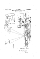
- Figure 1 is a diagram of the engraving machine, with the carriage shown in side elevation.
- Fig. 2 is a plan view of the ca'rriageportion.
- F Fig. 3 is a section taken on the line 33 of rangement.
- Fig. 5 is an enlarged detail of the end of the drill, or reproducing tool.
- Fig. 6 is an enlarged section through the printing plate.
- the machine is illustrated a machine more especially intended for making halftones, or cameo relief plates, in which the ink is deposited on the surface of the plate.
- the machine may be adapted for mechanical gravure work where parallel lines shaded in width are used, or for intaglio plates where the ink is deposited in the recess and the surface wiped off.
- FIG. 4 is a diagram showing a modified ar-v I may use whatever alternatives or equivathat the exigencies of varying conditions may demand without departing from the broad scope of the invention.
- the picture or image which is to be translated into an engraving is scanned by a beam of llght which successively travels over its entire surface.
- This beam of light modified by the varying lights and shades of the subject is directed onto the light-sensitive surface of a photo-electric cell, which correspondingly q varies the input of an amplifying circuit, the
- the picture 7 and the plate 8 which is to be engraved are mounted in spaced relation on the surface of the carriage 9.
- the carriage is longitudinally slidable on the sub-carriage 10, which is mounted transversely slidable on the base 11.
- the carriage 9 is resiliently pressed to the right as shown in Fig. 1 by means of a coil spring 12 which bears'against a lug 13, integral with the sub-base 10.
- a cam roller 14 is rotatably mounted on the opposite end of the carriage member 9, and is pressed into contact with the periphery of the driving cam 15 which is rotatably mounted on the sub-baselO.
- the cam 15 is' continuously rotated b 'means of the motor 16 mounted on the subase 10, and connected through any suitable form of speed reducing transmission as represented at 17.
- the profile of the cam 15 is such that the carriage is reciprocated at an even rate of speed in either direction.
- the sub-base 10 is moved laterally by means of the feed screw 18, which is rotatably mounted in the sub-carriage, and engages in a feed nut 19 which is attached to the base 11.
- This feeding is accomplished by means of a pawl and ratchet actuated by the pin 20, which is mounted on the carriage 9.
- the ratchet wheel 21 is fixedly secured to the outer end of the feed screw 18, and the pawl 22 is pivotally mounted on the upper end of the lever 23 which is rotatably mounted on the feed screw 18.
- the lower end of the lever 23 is connected by means of the link 24 to a plunger 25 which is slidably mounted in a housing 26, secured to the sub-carriage 10.
- the plunger 25 is resiliently pressed to the left as viewed in Fig. 1 by means of the coil spring 26, this movement being stopped by the collar 27 which is secured on the right end of the plun er 25, and strikes against the housing 26. t the end of the movement to the right, the pin 20 strikes the end of the plunger 25, and moves the ratchet wheel 21 counter-clockwise. When the carriage moves to the left, the pin 20 strikesdirectly on the pawl 22, and again moves the carriage in the same direction.
- the means for directing a beam of light against the picture is shown as comprising a suitable source of light 30- and a lens 31 for focusing the light.
- the beam is directed against the picture at an angle, and the reflected light is focused by means of the lens 32 upon a suitable photo-electric cell 33.
- the members 30, 31, 32 and 33 are mounted in fixed relation with the base 11.
- the engraving tool 34 is also mounted in a fixed position'with'relation to the base 11, to operate on the surface of the plate 8.
- the tool 34 is mounted to rotatein a frame 35 which is pivoted on a shaft 36 which is in fixed relation to the base-"11.
- the frame 35 is resiliently lifted by means of a contractile spring 37. against the fixed stop 38, and is pulled downwardly by means of the electromagnet 39.
- a small motor 40 is shown mounted on the frame 35 for rotating the engraving tool, and the motor is also connected for driving a circuit breaker-41, also mounted on the frame 35.
- the photo-electric cell 33 is connected by means of a conductor 42 through the battery 43 and the primary coil 44 of a transformer 45.
- the secondary 46 of the transformer 45 is connected in circuit with the grid 47 of the three-element tube 48 which is connected through the second'tube 49 to the circuit 50 to amplify current which flows through the photo-electric cell 33.
- the circuit 50 includes the electro-magnet 39 and is connected through the interrupter 41 as shown.
- the lighter spots'in the picture will increase the amount of energy in the electromagnet 39 and draw the graver," or cutting tool 34 deeper into the surface of the plate; while less light will be reflected from the' darker spots in the picture, and the amount of energy in the magnet 39 and the penetration of the tool will be proportionately decreased.
- the fluctuations in the reflected beam will be translated continuously into the amplifying circuits, and to the circuit 50, but the-tool will be fed downwardly in an intermittent manner because of the action of the circuit interrupter 41.
- the tool 34 is pulled down by the magnet 51 against a stop 52,.and is controlled by the fluctuating currents, as in the preceding form.
- the tool 34 is mounted to rotate in the frame 53, which is pivoted on a'fixed shaft 54.
- the motor 56 is connected to drive the tool and also the circuit breaker 57.
- the frame is retracted as before by a spring 58 against a fixed stop 59, but the output circuit 50 is connected through the circuit breaker 57 and he stop controlling electro-magnet 60; and the pulled-down magnet 51 is energized from the local batter 61 through the opposite side of the circuit reaker 57.
- the stop'mem'ber 52 is represented as being slidably mounted on a suitably fixed support 63, and isv provided with an inclined cam surface 64 to cooperate with a pointed contacting member 65, which is fixed on the frame 53.
- the stop member 52 will be positioned responsive thereto so that the contact 65 strikes on higher or lower portions of the cam surface 64. Since the pulled down magnet 51 is energized at regular intervals and the position of the stop 52is controlled by the amount of light reflected at the points in the picture, the image will be engraved on the surface 8 ready for printing.
- FIG. 5 A proposed form of the point of the engravin tool is shown in Fig. 5.
- the point is pro led so that, for even graduations in depth, the diameter increases in a regular manner; the object being to proportion it so that the area of the surface removed is a direct function of the depth of the cut.
- the greater portion of'the surface is left untouched to represent a dark portion of the picture, a part of the surface is cut away to represent the middle tones, etc., and all of the surface is removed by the tool to represent white portions of the picture.
- a machine for reproducing a picture on the surface of a plate comprising a transmitter including-means for scanning the picture and transforming the variations of shading into electrical pulsations, a translator connected to the transmitter-and including a plate cutting tool controlled by said pulsations, and an interrupter for interrupting the electrical pulsations between the translator and the transmitter to cause the tool to cut inte mittently.
- a machine for reproducing a picture on the surface of a printing plate comprising means for directing a beam of light to travel continuously over the picture, a means for transforming the variations in the light reflected from the picture into a pulsating electrical current, a plate cutting tool controlled by the current, and an interrupter for the current to cause the tool to out intermittently.
- a translator comprising a movably mounted frame, a drill rotatably mounted in the frame, means for reciprocating the frame to feed the drill into the plate, an adjustable stop for the frame for regulating said feeding movement, and electromagnetic means controlled by the shading on the picture for adjusting the stop.
- a translator comprising a pivotal'ly mounted frame, a drill rotatably mounted in the frame, means for reciprocating the frame to feed the drill into the plate, a movable stop havin an inclined surface cooperating with the f r tric means for positioning the stop in accordance with the shading of the picture.
- a holder for an image and for a plate for receiving an engraved reproduction of an image an engraving tool having a tapered cutting point, a primary electrical circuit, light sensitive means for varying the resistance of said circuit, means for focusing on said sensitive means light reflected from an image on said holder, a secondary circuit with amplifying means therein, an interrupter in said secondary circuit, and electromagnetic means for operating said drillunder the control of 7 said secondary circuit.
- light sensitive means comprising a photo-electric cell for varying the current in said circuit, means for focusing on said sensitive means light reflected from an image on said holder, a secondary circuit with grid control amplifying means therein, and electromagnetic means for operating said tool under the control of the output of the amplifying means.
- a suitable sub 'fying means therein, and electromagnetic ject means for scanning the subject, a photoelectric cell, an amplifying system modulated by the light and shade of the subject impressed on'the cell, and means for producing an engraved plate of the selected subJect by the output of the amplifying system.
- a machine for photo-electric engraving means for scanning a subject with a photo-electric cell, means for amplifying the current fluctuations of the photo-electric cell, an engraving tool, means for causing the amlified current fluctuations to osition the depth of the engraving tool WhlCh is so tapered as to engrave areas that are a function of the depth of the cut as directed by the light andshadeof the subject scanned.
- sur ace cooperating with frame to stop the feeding movement of the frame, and electromagnetic means controlled by the shading on the picture for positioning the stop.
- holder for an image and for a plate for receiving an engraved reproduction of an im age, an engraving tool aving a tapered cutting point, a primary electrical cireuit,light sensitive means for varying the resistance of and circuit, means for focusing on said sensi-
Landscapes
- Engineering & Computer Science (AREA)
- Manufacturing & Machinery (AREA)
- Manufacture Or Reproduction Of Printing Formes (AREA)
Description
June 13,- 1933; w. HOWEY 1 MACHINE FOR PRODUCING PRINTING PLATES Filed Oct. 19, 1929 3 Sheets-Sheet 1 June 13, 1933. w ow 1,914,258
MACHINE FOR PRODUCING PRINTING PLATES Filed 001,- 19, 1929 I 3 Sheets-Sheet 2 cj tiarny June 13, 1933. HQWEY 1,914,258
MACHINE FOR PRODUCING PRINTING PLATES Filed Oct. 19, 1929 5 Sheefs-Sheet 3 @Za'mai? Patented June 13, 1933 PATENT oFFIcE waLrm HOWEY, or YORK, N. Y.
MACHINE FOR PRODUCING PRINTING PLATES Application filed October 19, 1929. Serial No. 400,981.
' My invention relates to improvements in the process of-vacuum tube engraving and it more especially consists of the features pointed out in the claims. The purpose of my invention is to provide an automatic engraving process which eliminates the many steps of half-tone engraving as they are now practiced; that translates a picture into an engraving by means of a light sensitive cell which modifies the input of an amplifying system; that includes vacuum tubes having a plurality of elements; that uses the output. of the amplifying system for automatically controlling a cutting tool to engrave the light and shade variations of the picture or photograph in any'desired material; and that, in short, produces engravings automatically by means of a photo-electric cell, one or more vacuum tube amplifica- 1 2 tions, and the power output of the amplifying circuit to direct the engraving tool.
With these and other ends in view, I illustrate in the accompanying drawings such instances of adaptation as will disclose the broad scope of the invention without limiting myself to the specific details shown thereon and described herein.
Figure 1 is a diagram of the engraving machine, with the carriage shown in side elevation.
Fig. 2 is a plan view of the ca'rriageportion. F Fig. 3 is a section taken on the line 33 of rangement.
Fig. 5 is an enlarged detail of the end of the drill, or reproducing tool.
Fig. 6 is an enlarged section through the printing plate.
In the drawings is illustrated a machine more especially intended for making halftones, or cameo relief plates, in which the ink is deposited on the surface of the plate. Obviously. the machine may be adapted for mechanical gravure work where parallel lines shaded in width are used, or for intaglio plates where the ink is deposited in the recess and the surface wiped off.
lents of construction and cooperating parts Fig. 4 is a diagram showing a modified ar-v I may use whatever alternatives or equivathat the exigencies of varying conditions may demand without departing from the broad scope of the invention.
In the adaptation instancedin the drawings the picture or image which is to be translated into an engraving is scanned by a beam of llght which successively travels over its entire surface. This beam of light modified by the varying lights and shades of the subject is directed onto the light-sensitive surface of a photo-electric cell, which correspondingly q varies the input of an amplifying circuit, the
out at of which controls the engraved depth an variation of cut of a tapered tool in accordance with the variations of light and shade of the subject.
The picture 7 and the plate 8 which is to be engraved are mounted in spaced relation on the surface of the carriage 9. The carriage is longitudinally slidable on the sub-carriage 10, which is mounted transversely slidable on the base 11. The carriage 9 is resiliently pressed to the right as shown in Fig. 1 by means of a coil spring 12 which bears'against a lug 13, integral with the sub-base 10. A cam roller 14: is rotatably mounted on the opposite end of the carriage member 9, and is pressed into contact with the periphery of the driving cam 15 which is rotatably mounted on the sub-baselO. The cam 15 is' continuously rotated b 'means of the motor 16 mounted on the subase 10, and connected through any suitable form of speed reducing transmission as represented at 17. The profile of the cam 15 is such that the carriage is reciprocated at an even rate of speed in either direction.
At the end of each reciprocation of the carriage 9, the sub-base 10 .is moved laterally by means of the feed screw 18, which is rotatably mounted in the sub-carriage, and engages in a feed nut 19 which is attached to the base 11. This feeding is accomplished by means of a pawl and ratchet actuated by the pin 20, which is mounted on the carriage 9. The ratchet wheel 21 is fixedly secured to the outer end of the feed screw 18, and the pawl 22 is pivotally mounted on the upper end of the lever 23 which is rotatably mounted on the feed screw 18. The lower end of the lever 23 is connected by means of the link 24 to a plunger 25 which is slidably mounted in a housing 26, secured to the sub-carriage 10. The plunger 25 is resiliently pressed to the left as viewed in Fig. 1 by means of the coil spring 26, this movement being stopped by the collar 27 which is secured on the right end of the plun er 25, and strikes against the housing 26. t the end of the movement to the right, the pin 20 strikes the end of the plunger 25, and moves the ratchet wheel 21 counter-clockwise. When the carriage moves to the left, the pin 20 strikesdirectly on the pawl 22, and again moves the carriage in the same direction.
The means for directing a beam of light against the picture is shown as comprising a suitable source of light 30- and a lens 31 for focusing the light. The beam is directed against the picture at an angle, and the reflected light is focused by means of the lens 32 upon a suitable photo-electric cell 33. The members 30, 31, 32 and 33 are mounted in fixed relation with the base 11.
The engraving tool 34 is also mounted in a fixed position'with'relation to the base 11, to operate on the surface of the plate 8. The tool 34 is mounted to rotatein a frame 35 which is pivoted on a shaft 36 which is in fixed relation to the base-"11. The frame 35 is resiliently lifted by means of a contractile spring 37. against the fixed stop 38, and is pulled downwardly by means of the electromagnet 39. A small motor 40 is shown mounted on the frame 35 for rotating the engraving tool, and the motor is also connected for driving a circuit breaker-41, also mounted on the frame 35. From the above description, it will now be seen that the picture is scanned in a series of parallel lines by the light beam, and that the rotating tool travels over the surface of theplate in exactly the same manner as the beam travels over the surface of the picture.
The photo-electric cell 33 is connected by means of a conductor 42 through the battery 43 and the primary coil 44 of a transformer 45. The secondary 46 of the transformer 45 is connected in circuit with the grid 47 of the three-element tube 48 which is connected through the second'tube 49 to the circuit 50 to amplify current which flows through the photo-electric cell 33. The circuit 50 includes the electro-magnet 39 and is connected through the interrupter 41 as shown. v
Since the amount of current that can flow through the photo-electric cell 33 increases according to the amount of light reflected into the cell, the lighter spots'in the picture will increase the amount of energy in the electromagnet 39 and draw the graver," or cutting tool 34 deeper into the surface of the plate; while less light will be reflected from the' darker spots in the picture, and the amount of energy in the magnet 39 and the penetration of the tool will be proportionately decreased. The fluctuations in the reflected beam will be translated continuously into the amplifying circuits, and to the circuit 50, but the-tool will be fed downwardly in an intermittent manner because of the action of the circuit interrupter 41.
In the form shown in Fig. 4, the tool 34 is pulled down by the magnet 51 against a stop 52,.and is controlled by the fluctuating currents, as in the preceding form. The tool 34 is mounted to rotate in the frame 53, which is pivoted on a'fixed shaft 54. The motor 56 is connected to drive the tool and also the circuit breaker 57. The frame is retracted as before by a spring 58 against a fixed stop 59, but the output circuit 50 is connected through the circuit breaker 57 and he stop controlling electro-magnet 60; and the pulled-down magnet 51 is energized from the local batter 61 through the opposite side of the circuit reaker 57. As the magnet 60 is energized it attracts a diaphragm 62, to which the end of the stop member 52 is attached. The stop'mem'ber 52 is represented as being slidably mounted on a suitably fixed support 63, and isv provided with an inclined cam surface 64 to cooperate witha pointed contacting member 65, which is fixed on the frame 53.
As the reflection of the beam of light from .the picture varies, the stop member 52 will be positioned responsive thereto so that the contact 65 strikes on higher or lower portions of the cam surface 64. Since the pulled down magnet 51 is energized at regular intervals and the position of the stop 52is controlled by the amount of light reflected at the points in the picture, the image will be engraved on the surface 8 ready for printing.
A proposed form of the point of the engravin tool is shown in Fig. 5. The point is pro led so that, for even graduations in depth, the diameter increases in a regular manner; the object being to proportion it so that the area of the surface removed is a direct function of the depth of the cut. Thus, as shown in Fig. 6, the greater portion of'the surface is left untouched to represent a dark portion of the picture, a part of the surface is cut away to represent the middle tones, etc., and all of the surface is removed by the tool to represent white portions of the picture.
I claim: p 1. A machine for reproducing a picture on the surface of a plate, comprising a transmitter including-means for scanning the picture and transforming the variations of shading into electrical pulsations, a translator connected to the transmitter-and including a plate cutting tool controlled by said pulsations, and an interrupter for interrupting the electrical pulsations between the translator and the transmitter to cause the tool to cut inte mittently.
current to cause the tool to out intermittently 3. A machine for reproducing a picture on the surface of a printing plate, comprising means for directing a beam of light to travel continuously over the picture, a means for transforming the variations in the light reflected from the picture into a pulsating electrical current, a plate cutting tool controlled by the current, and an interrupter for the current to cause the tool to out intermittently.
4. The combination in a machine for reproducing a picture on a plate, of a drill mounted to travel over the surface of'the plate and normally raised therefrom, an electro-magnet for feeding the drill into the plate, a photoelectric cell controlling the amount of feedin a circuit including an electrical source and the electromagnet, and an interrupter in said circuit. Y
5. In a machine for reproducing a picture on the surface of a plate, a translator comprising a movably mounted frame, a drill rotatably mounted in the frame, means for reciprocating the frame to feed the drill into the plate, an adjustable stop for the frame for regulating said feeding movement, and electromagnetic means controlled by the shading on the picture for adjusting the stop.
6. In a machine for reproducing a picture on the surface of a printing plate, a translator comprising a pivotal'ly mounted frame, a drill rotatably mounted in the frame, means for reciprocating the frame to feed the drill into the plate, a movable stop havin an inclined surface cooperating with the f r tric means for positioning the stop in accordance with the shading of the picture.
7. In a machine for reproducin a picture ame to limit the feeding movement, and photo-elec-.
tive means light reflected from an image on said holder, a secondary circuit with amphmeans for operating said drill under the control of said secondary circuit.
9. In a machine of the class described, a holder for an image and for a plate for receiving an engraved reproduction of an image, an engraving tool having a tapered cutting point, a primary electrical circuit, light sensitive means for varying the resistance of said circuit, means for focusing on said sensitive means light reflected from an image on said holder, a secondary circuit with amplifying means therein, an interrupter in said secondary circuit, and electromagnetic means for operating said drillunder the control of 7 said secondary circuit.
10. In an engraving machine, a holder for an image and for a plate for receiving an engraved' reproduction of an image, an engraving tool having a tapered cutting point, a
primary electrical circuit, light sensitive means comprising a photo-electric cell for varying the current in said circuit, means for focusing on said sensitive means light reflected from an image on said holder, a secondary circuit with grid control amplifying means therein, and electromagnetic means for operating said tool under the control of the output of the amplifying means.
11. In automatic engraving, a suitable sub 'fying means therein, and electromagnetic ject, means for scanning the subject, a photoelectric cell, an amplifying system modulated by the light and shade of the subject impressed on'the cell, and means for producing an engraved plate of the selected subJect by the output of the amplifying system.
12. In a machine for photo-electric engraving, means for scanning a subject with a photo-electric cell, means for amplifying the current fluctuations of the photo-electric cell, an engraving tool, means for causing the amlified current fluctuations to osition the depth of the engraving tool WhlCh is so tapered as to engrave areas that are a function of the depth of the cut as directed by the light andshadeof the subject scanned.
In testimony whereof I affix my slgnature.
,WALTER HOWEY.
sur ace cooperating with frame to stop the feeding movement of the frame, and electromagnetic means controlled by the shading on the picture for positioning the stop.
8. In a machine of the class described, a
holder for an image and for a plate for receiving an engraved reproduction of an im age, an engraving tool aving a tapered cutting point, a primary electrical cireuit,light sensitive means for varying the resistance of and circuit, means for focusing on said sensi-
Priority Applications (1)
| Application Number | Priority Date | Filing Date | Title |
|---|---|---|---|
| US400931A US1914258A (en) | 1929-10-19 | 1929-10-19 | Machine for producing printing plates |
Applications Claiming Priority (1)
| Application Number | Priority Date | Filing Date | Title |
|---|---|---|---|
| US400931A US1914258A (en) | 1929-10-19 | 1929-10-19 | Machine for producing printing plates |
Publications (1)
| Publication Number | Publication Date |
|---|---|
| US1914258A true US1914258A (en) | 1933-06-13 |
Family
ID=23585588
Family Applications (1)
| Application Number | Title | Priority Date | Filing Date |
|---|---|---|---|
| US400931A Expired - Lifetime US1914258A (en) | 1929-10-19 | 1929-10-19 | Machine for producing printing plates |
Country Status (1)
| Country | Link |
|---|---|
| US (1) | US1914258A (en) |
Cited By (8)
| Publication number | Priority date | Publication date | Assignee | Title |
|---|---|---|---|---|
| US2731878A (en) * | 1956-01-24 | sherwin | ||
| US2769199A (en) * | 1952-07-01 | 1956-11-06 | Fairchild Camera Instr Co | Engraving stylus |
| US3086134A (en) * | 1959-02-18 | 1963-04-16 | Oerlikon Buehrle Ag | Device for the two-dimensional arrangement, variable according to pattern, of a plurality of elongated control means for multi-member machines |
| US3109888A (en) * | 1960-10-14 | 1963-11-05 | Time Inc | Scanning mechanism for facsimile reproduction system |
| US3202024A (en) * | 1961-03-16 | 1965-08-24 | Textron Inc | Pattern controlled tool |
| US3659110A (en) * | 1970-06-02 | 1972-04-25 | Recognition Equipment Inc | Document reader transport comprising a positioning guide which includes a track of magnetic material |
| FR2181446A1 (en) * | 1972-04-24 | 1973-12-07 | Franklin Mint Corp | |
| US3936942A (en) * | 1974-12-11 | 1976-02-10 | National Aeronautics And Space Administration Office Of General Counsel-Code Gp | Optical pantograph |
-
1929
- 1929-10-19 US US400931A patent/US1914258A/en not_active Expired - Lifetime
Cited By (8)
| Publication number | Priority date | Publication date | Assignee | Title |
|---|---|---|---|---|
| US2731878A (en) * | 1956-01-24 | sherwin | ||
| US2769199A (en) * | 1952-07-01 | 1956-11-06 | Fairchild Camera Instr Co | Engraving stylus |
| US3086134A (en) * | 1959-02-18 | 1963-04-16 | Oerlikon Buehrle Ag | Device for the two-dimensional arrangement, variable according to pattern, of a plurality of elongated control means for multi-member machines |
| US3109888A (en) * | 1960-10-14 | 1963-11-05 | Time Inc | Scanning mechanism for facsimile reproduction system |
| US3202024A (en) * | 1961-03-16 | 1965-08-24 | Textron Inc | Pattern controlled tool |
| US3659110A (en) * | 1970-06-02 | 1972-04-25 | Recognition Equipment Inc | Document reader transport comprising a positioning guide which includes a track of magnetic material |
| FR2181446A1 (en) * | 1972-04-24 | 1973-12-07 | Franklin Mint Corp | |
| US3936942A (en) * | 1974-12-11 | 1976-02-10 | National Aeronautics And Space Administration Office Of General Counsel-Code Gp | Optical pantograph |
Similar Documents
| Publication | Publication Date | Title |
|---|---|---|
| US2079310A (en) | Mechanism for producing printing plates by electric arcs | |
| US2092765A (en) | Electric machine | |
| US1914258A (en) | Machine for producing printing plates | |
| US2172313A (en) | Automatic reproducing process and machine | |
| US2086798A (en) | Photoelectrical device for producing half-tone cuts | |
| US2881246A (en) | Engraving machine | |
| US1719621A (en) | Machine for producing printing plates | |
| ES439875A1 (en) | Document positioning means for printing apparatus | |
| DE927813C (en) | Process for preparing screened clichés | |
| US2925464A (en) | Machine for producing a facsimile reproduction | |
| US2179002A (en) | Method and means for reproducing pictures | |
| CN104742494A (en) | Screen making method of digital printing imitating flat screen | |
| US2112010A (en) | Apparatus for producing printing plates | |
| ZA838229B (en) | Method and apparatus for setting and monitoring an exposure spot for printing | |
| US2079970A (en) | Process and apparatus for photoelectric engraving | |
| US2880270A (en) | Method of and apparatus for electromechanicaly producing printing forms from line-originals | |
| US2209183A (en) | Printing plate and method of and apparatus for producing it | |
| US2047851A (en) | Machine for reproducing printing plates from pictures | |
| US2076220A (en) | Method of and means for producing printing plates | |
| US2160951A (en) | Process and device for the reproduction of designs on printing plates by means of photoelectrically controlled gravers | |
| US1933792A (en) | Engraving | |
| DE918551C (en) | Process for the production of copy templates | |
| US2238601A (en) | Telephotography | |
| US2638500A (en) | Process and apparatus for photoelectric engraving | |
| US5575931A (en) | Apparatus for engraving on a rubber cylindrical matrix |