US1902123A - Control circuit for switches for automatic telephone systems - Google Patents
Control circuit for switches for automatic telephone systems Download PDFInfo
- Publication number
- US1902123A US1902123A US602190A US60219032A US1902123A US 1902123 A US1902123 A US 1902123A US 602190 A US602190 A US 602190A US 60219032 A US60219032 A US 60219032A US 1902123 A US1902123 A US 1902123A
- Authority
- US
- United States
- Prior art keywords
- contacts
- switch
- relay
- circuit
- closed
- Prior art date
- Legal status (The legal status is an assumption and is not a legal conclusion. Google has not performed a legal analysis and makes no representation as to the accuracy of the status listed.)
- Expired - Lifetime
Links
Images

Classifications
-
- H—ELECTRICITY
- H04—ELECTRIC COMMUNICATION TECHNIQUE
- H04Q—SELECTING
- H04Q3/00—Selecting arrangements
Definitions
- My presentinvention has for its objectto provide a circuit arrangement for controlling the stepping movement of switches used in automatic telephone systems and their release 5 together with additional mechanism desired the creation of current impulses over the two wires leading from a telephone sub scribers station by means of relays,'or their equivalent located in the two sides of the subscribers line and other associate relays" v connection with'two slow release relays and operating in conjunction with them and with the motor and release magnets of the switch.
- the first two mentioned relays are simultaneously energized and retained inthis condition while the line isin use, the contacts controlled by said relays being influenced and one.
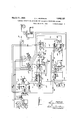
- FIG. 1 is a diagrammaticview showinga circuit arrangement d sclosing, one embodi- Jnent ofmy invention
- Fig.2 is-a fragmentary illustration showing a front'elevation of a simple form of switch by reference to which an understanding of the operation of the circuitsjvill be facilitated
- Fig.3 is a crosssectional view. on'the line 3w'3mof Fig. 2
- Fig.4 is'a detail view showing the arrangement of thevconta'cts of the subs'cribers impulse transmitter.: Similar reference numerals of the several figures indicate similar parts.
- I provide a" new arrangement of the dialing contacts and the control "relays in the subscribter and supervision of the subscribersline' bank in which insulated terminals are ar- 15 ranged in sets such as indicated by 1, 2 and 3 Fig. 3) the first two comprising terminals for anincoming subscribers line wires and.
- a coil spring 7 of; the required tensionis connected to, the journal 4 and its support-' ingiraine serves to restore theswitch wipers to their normal position when they are released as indicated in Fig. 2.
- the switchis further provided with sets of off-normal contactsprings 8, 9. and 10 which are arranged above and at one side of the ratchet wheel 5. on a supper orbrackct 11. Mounted n con.-
- the dialing device also embodies a series of contacts two'o-f which are make contacts and eet whi h'a e eak on acts their assent,
- the latter further comprises bly being such that the making contacts are closed before the breaking contacts are open.
- Illustrative ofthese features I have shown three springs 16, 17 and 18 supported in a holder 19.
- Spring 17 has a tip 17a resting against spring 16.
- Beneath the latter is the spring 18 carrying on its upper side a contact 18a and on its lower side a.
- stud 186 which when acted upon by the rotatable member 13 will close the contact 18a tofirst engage the spring .16 andthereafter elevate it to break the connection between the points 17a and spring 16;
- a finder switch the function of which is to'connect the calling line to an idletrunk leading to a connector switch over which the desired connection can be effected by the transmission of the required number of impulses representing digits to advance its wipers into engagement withthe terminals of the called partys line.
- I su'bscribers station A appear as terminals A B of a line finder switch F to'which the conductorsA and B are joined by wires A and B
- the wipers f and f of the finders switch are terminals of a trunk, comprising 1 the conductors A B leading to the connector To this end the line wires from the switch control mechanism at which point they lead through the main control relay A.
- the efi'ect of the connection of the line finder switch F is to extend the calling line and to place the concuit beyond this -point,by conductors A B", through relays which are actuated when the called party answers so that a talking con nection is established between the Calling and called partys stations through the advanced position of the connector switch wipers.
- the function of the contact spring 18- of the impulse transmitter is to provide means for furnishing a ground connection to one of the two conductors of the subscribers line and to this end it is grounded at the sub scribers stat-ion as indicated at 180.
- I provide a main operating relay A which is in circuit with battery X which is the usual central ofiice storage battery havinga grounded connection 00 leading from its positive pole; I arrange relay is on the wet or battery side of the line it will when energized operate to close a pair of contacts a and the associate relay on the dry side of the line, servesto open a pair or.
- the contacts a apply a grounded connection a through conductor 20 to the contacts 0 which control the stepping movement of the motor magnet of the switch in response to impulses transmitted by the action of the subscribers dialing device.
- the main and associatecontrol relays are simultaneously energized and the spring '18 maintaining a battery connection through the main control relay when the contacts 16 and 17 are disrupt-ed will retainits contacts a closed continuously while the receiver switch hook cont-acts are closed.
- the motor magnet is intermittently, energi-Zed by the closing of the contacts 0 on the associate control relay C, butas this relay remains energized over the closed subscribe ers circuit after the transmission of the last impulse from the dialing device, it is neces sary to provide.
- in the circuit of the motor magnet means for maintaining its continuity during the period the impulses are. being transmitted, said means being so arranged that it is actuated upon the first impulse.
- the ringing current for signaling the called part-ys line is controlled by the ringing relay Q,- supplied with current from the batteryX and its circuit terminates in the iacl; contact q of armature g which in its forward movementengages the forward contact p of the busy test relay.
- the ringing current apparatus may be an alternating current ringing machine N and a source of direct current N- the circuit for which terminates in armatures g on the relay Q. Then the latter is energized said armatures engage with forward contacts which in turn are connected to the called partys line by the conductors 36 and 37.
- a transformer N has its twowindings included in the'A. C. and D.C. circuits just mentioned so that the A. C. ringing current is dispatched when the armatures 9 are attracted. In order that this ringing current may be applied intermittently there is placedin the A. C. circuit a come n'iutator it. I V
- the second J'a'rmature s normally engages the back contact 8* which 18 the terminal of the other ringing conductor 36.
- a third armature '8 is mounted on'the relay S engaging a back contact 8 whlch is also connected to the conductor 38.
- On the relay T is an armaturet engaging the back contact if.
- the armature t is connected by the conductor 43 to battery X through resistances and the armature s and back contact t are oined by the conductor 44.
- the pulling up of the armatures s and s connects the conductor 39 and 40, leading from the switch wipers, to forward contacts 8 and 88 from which lead conductors 45 and L6 to arn'iatures u and u on the called partys answeringrelay U.
- the forward contacts of these armatures are terminals for the call ing line AB.
- the relay U is provided with two windings u and a each of Which 1s ooI1- nected at one end to the conductors 455 and 46.
- the. switch wiper 3a comes to; rest on a busy or grounded terminal with the result that a circuit is established through the battery X the winding 12' and the armature .32'before the latter is released from the position in which. it was attracted when the winding. 7) is energized by the closing of the test contacts m upon each step ofthemotor magnet.
- a telephone switching system comprising telephone line circuit conductors each having a control relay provided respectively with normally open and normally closed pairs of contacts,.animpulse transmitter having a pair of breaking contacts and a pair of making. contacts, a sourceof'current normally maintained over the telephone circuit by said breaking contacts'andi suppliedto one side of said circuit by thefclosureof the making contacts, aswitch having a: motor magnet provided w1than operatmg circuit.
- a telephone switchingsystem comprising an impulse transmitter having a pair of a closed breaking-contactsand' a pair of'open making contacts arranged to operate in uni son with thelatter contact s closing before the former open, a telephone line normally closed through thefirst mentioned contacts and comprising two controlrelays each provided with sets of contacts, a source of current for the telephone line also connected to the making contacts of the transmitteni v switch havingjamotor magnet'providedjwith a circuit eration of; said transmitter.
- a telephone switching system comprlsbreaking contacts and a pair of. making concircuit, a source of battery current connected to the two conductors with the dry side thereof leading through the making contacts of the transmitter, and a switch havinga motor magnet provided with a circuit controlledby saidicontrol.relays; Y 5 In a telephone system, the combination with a'telephone line, a control relay having; a pan of contacts and an impulse transmitter in!
- a switch comprising a mov- I able element, and a pair 'of oft-normal con its normal position, of a motor magnet providedwlth a circuit leading through the control relay contacts and through the off normal contacts and a bridging relay in the motor magnet circuit-having a pair of contacts.
- the combination phone circuit conductors leading therethrough and a control relay in one of said conductors having a pair of contacts'adapted to vibrate in response to the transmitter, of a switch having a movable element, a pair of contacts closed thereby when the switch is in its nor'mal'position, a slow releasing relay having a pair of contacts and adapted to be energized upon the first impulse dispatched upon the action of the transmitter, and a motor-'magnet for'driving'the switch having-a circuit leading through the slow .relay contacts andthe'off normallcontacts on the first impulse transmitted and subsequently receive inggim'pulsesthrough the slow relay contacts.
- a telephone system switching mechanism comprising an impulse transmitter, a subscribers circuit leading therefrom, a control relay' therein having contacts vibrating in response to said transmittenaswitch comprising a motonmagnet, a pair of contacts closed by the switchfin its normal position, a
- slow releasing relay having an open pair of remain closed by the energization ofsaid relayv in response to the action of the transmitter, a circuit for the motor magnetleading through i the slow relay winding and throughfits. contacts and the ofi-normal switch contacts.
- a telephone switching mechanism comprising an impulse transmitter, a telephone circuit leading therefrom having :receiver hook contacts, a control relay in said circuit having contacts which are closed in unison with said hook contacts, a'sw'itch having a:
- a telephone switching mechanism comprising an impulse transmitter, a telephone circuit leading therethrough having receiver hook contacts, a control relay in said circuit having contacts which are closed in unison with said hook contacts, a switch and means for driving it in response to the action of the transmitter, a pair of off-normal contacts which are closed by the switch in its normal position, a release magnet operating 'to hold the switch against retrograde movement, a circuit therefor leadingthrough the" ofl-normal contacts and'control relay con-f tacts, and a branch circuit having a'pairfof contacts adapted to be closed to bridge the;
- Atelephone system control relay and an impulse transmitter, a pair of contacts on the relay which are closed ;when the. circuit through the conductor is closed, a switch, driving devices foroperating it in response tothe action of the transmitter, means for locking the switch against retrograde movement" comprising a release magnet lfor act'uating said meansin unison with'the closure of the subscriber sline, and a holding circuit for said magnet extending through.
- a teleplione syst'em comprising a subscribers line circuit, a ,control relay therein having a pair of grounded contacts which are closed in response to theclosure of said line, an impulse transmitterfon'said line, aswitch provided'with terminalsfor the latter and also comprising a corresponding busy terminal, wipers cooperating'with said termina-ls, 1nean s i'or driv ng the switch upon the operation "of the transmittercomprisinga motor magnet anda'inotor control relay having a pairof contacts ⁇ which are closed when said"r'elay is dee'nergized, mechanism for holding the switch against retrogrademovenient'c'om'prising a release magnet, apair of ofi-normal contacts which are opened when the switch is in normal position, a busyswitch indicating circuit extending from the, busyterminal' wip'erthrough thethen closed 1 off n'ormal contacts and to" ground atthe' controlrelay contacts upon cess
- an limpulsetransmitter having a pair of closed line terminals and free grounded cfontact, subscribers line conductors connected to the closed terminals, means for operating theme contact to closed ground through one of said conductorsand subsequently open the a closed line terminalsintermittently, a maincontrol relay in the grounded side of the sub scribers line,'ai1 associate relay in the other side of 'said'line, a source of current for-said line, a pair of contacts closed by the main relay, a pair ofcontacts openedand released a by the associate'relay each time the circuit through the'line'conductorsisinterrupted, a V
- a subscribers impulse transmitter having a pair of closed contacts, an additional free grounded contact and means for operating the latter to connect ground to one of the line conductors and to open the closed contacts momentarily, a pairof line conductors leading from said closed terminals respectively to said switch, amain control relay in the conductor thus grounded by said additional contact, an associate relay in the other conductor, a source of current for said line and for operating the switch having a ground connection, a pair of contacts on the main control relay for closing the connection from the source of current, a pair of contacts on the associate relay adapted to vibrate in response to interruptions of current in the subscribers circuit, a motor magnet for stepping the switch on each of said current impulses, a release magnet for holding the switch in its advance position having a cir cuit maintained during the operation of the switch through the ground established by the main control relay contacts, off-normal contacts adapted to be closed when the switch is advanced, a busy test circuit extending from the busy test wiper through said closed of
Landscapes
- Engineering & Computer Science (AREA)
- Computer Networks & Wireless Communication (AREA)
- Structure Of Telephone Exchanges (AREA)
Description
March 21, 1933. GQQDRUM 1,902,123
CCNTRCL CIRCUIT FOR SWITCHES FOR AUTOMATIC TELEPHONE SYSTEMS Filed March 31, 1932 2 Sheets-Sheet 1 6% XINVENTQR- A/MZLUMWLM HIS ATTORNEYS March 21, 1933. c. GOODRUM 1,902,123
CONTROL CIRCUIT FOR SWITCHES FOR AUTOMATIC TELEPHONE SYSTEMS Filed March 3'1, 1932 2 Sheets-Sheet 2 91 T g z:
IIIIIIIIII/II/II/II/IJ HIS ATTORNEYS.
Patented Mar. 21, 1933 UNITED STATES ATENT OFFICE CHARLES L. GOQDRUM, or
conrnor. omovrr ron swrronns FOR-Annemarie. TELEPHONESYSTEMS Applicationlfiled Maria 31, 1932. serial No. "602,190;
My presentinventionhas for its objectto provide a circuit arrangement for controlling the stepping movement of switches used in automatic telephone systems and their release 5 together with additional mechanism desired the creation of current impulses over the two wires leading from a telephone sub scribers station by means of relays,'or their equivalent located in the two sides of the subscribers line and other associate relays" v connection with'two slow release relays and operating in conjunction with them and with the motor and release magnets of the switch. The first two mentioned relays are simultaneously energized and retained inthis condition while the line isin use, the contacts controlled by said relays being influenced and one. of them being caused to' vibrate inresponse to a subscribers impulse-transmitter which opens and closes the telephone circuit while the other is held in its closed or at tracted position.- Especial attention is given to the manner in which the contacts ofthe impulse transmitter, or dialing-device, are V I saturation n the cores of 'the slow releasing arranged and also to the battery connections leading therethrough and supplying the control relays with current so that the main control relay contacts are closed upon the closure of the telephone circuit and remain closed during the vibrations of thecontacts on the associate relay which intermittently actuates the motor magnet. By this arrangement the associate control relay is found to be upon the dryer, grounded side of the line sponds to the dialing impulses and the two in one or other ofthe line conductors.
Tothese and other ends my invention embodies further improvements all of which'will.
be fully described in the accompanying specification the novel featuresbeing particularly pointed out in the appended claims. In the drawings: I
More specifically my invention provides, for the accomplisl'nnents of these functions by I which adds to the fidelity with which it re Fig. 1 is a diagrammaticview showinga circuit arrangement d sclosing, one embodi- Jnent ofmy invention {Fig.2 is-a fragmentary illustration showing a front'elevation of a simple form of switch by reference to which an understanding of the operation of the circuitsjvill be facilitated; Fig; 3is a crosssectional view. on'the line 3w'3mof Fig. 2; and Fig.4 is'a detail view showing the arrangement of thevconta'cts of the subs'cribers impulse transmitter.: Similar reference numerals of the several figures indicate similar parts. I
In the present day: automatic telephone systems operating on the so-called two wire principle a single impulse relay is utilized in considerable difficulty is experienced due to riod of dwell ofthe vibrating contact or armammal theimpulse relay on its forward A'II-IENS, GEORGIA, ASSIGNOR OF ONE-HALF T0 LOUIS -G PAGFNT, OF NEW YORK,'IN. Y.
and back strokes; "maintaining an accurate" timing'of the subscribers impulse transmit-- relays over the entireperiod. required to dial the larger digits such as the Figures 7, 8 and 9. Azfurther difficulty is also encountered in. that a comparatively high voltage is re quired on the telephone lines to. operate the switch relays and magnets whichadds to the" maintenance and operating costs.
iAn'object of my invention is to provide a system which will operate satisfactorily, on a line voltage less thanone-half of that now' employed. and which'is not effected by a comparative'ly slow transmission of impulses or an lrregular"transmlsslon of such impulses from the subscribers dialing mechanism and c which is noteife'cted by theusual or more commonly experienced current leakage on "oneor both sides ofthe telephone circuit.
In accordance. with my invention I provide a" new arrangement of the dialing contacts and the control "relays in the subscribter and supervision of the subscribersline' bank in which insulated terminals are ar- 15 ranged in sets such as indicated by 1, 2 and 3 Fig. 3) the first two comprising terminals for anincoming subscribers line wires and.
the third'being for a busy test circuit for such line. I In practice it will be understood that where the system is extendedto a point where more than one switch is requiredffor interconnecting a large group of subscribers lines, additional switches are provided and these terminals are connected .in multiple or the switches are otherwise disposedto prof vide for the required classification ofser.v
ice. Rotatably mounted in front of the terminal bank are the coo eratin switchwi ers 1a,, 2a andfla carried on a journal to which is fixeda ratchet wheel 5. Spring lingers 1b, 2b and 3? extending inwardly from. a support 6 engage the hubs of the wipers,
A coil spring 7 of; the required tensionis connected to, the journal 4 and its support-' ingiraine serves to restore theswitch wipers to their normal position when they are released as indicated in Fig. 2. The switchis further provided with sets of off-normal contactsprings 8, 9. and 10 which are arranged above and at one side of the ratchet wheel 5. on a supper orbrackct 11. Mounted n con.-
junction withthese springs is an operating finger 12; extending into the path of a pin 5a which when thefswitch is advanced releases these sets of contacts. When. the switch is in its normal position springs 8 and 9 are closed against their cooperating contacts 8a and 9a and spring 10 is disengaged from its contactlOa. The. position of each ;,of these several contacts is reversed as soon as the switch is advanced one step.
In Fig. l I have shown diagrammatically a suitable arrangement of the contacts comprising part of the subscribers dialing device or transmitter. a rotary driving member 13-adapted to be 7 driven in one directionby the tension of a sprin 14. An oscillatory setting member in the form of a. ratchet wheel 13a is directly connected to the spring and when it isrestored to its original position causes the act-uator 13 tobe driven through the pawl 13b.
- The dialing device also embodies a series of contacts two'o-f which are make contacts and eet whi h'a e eak on acts their assent,
The latter further comprises bly being such that the making contacts are closed before the breaking contacts are open. Illustrative ofthese features I have shown three springs 16, 17 and 18 supported in a holder 19. Spring 17 has a tip 17a resting against spring 16. Beneath the latter is the spring 18 carrying on its upper side a contact 18a and on its lower side a. stud 186 which when acted upon by the rotatable member 13 will close the contact 18a tofirst engage the spring .16 andthereafter elevate it to break the connection between the points 17a and spring 16;
' The snbscribers telephone line when in use extends throughthe normally closed contact springs16 and 17as shown in Fig. 1 in which the line conductors are indicated'by A and B in one of which is'located the subscribers telephone apparatus comprising th'etransmitter T, receiver Rfand the us'ual switch hook contacts HQ ,The subscribers circuit extends through contacts 'to be further described and terminates in the switch wipers 1a and 2a. In order that this line may be called by other subscribers terminals are allocated to it on the switch bank. F or the purposes of description I have also illustrated in Fig. 1 a called partys' line'A and B? which represents one of several which terminate 'on different sets of switch terminals 1, 2 and 8. If the system requires two or more switches (a second switch being indicated at E) the corresponding terminals of the various lines are connectedin'inultiple as will be understood.
;In a telephone system designed to accommodate a considerable number of subscribers, it desirable to use a proportional number of switches which'are very much less in number than are the lines which are served, and to provide for the automatic selection of one of V the ron oflines on which a call ma be.
initiated. This is accomplished by a. finder switch the function of which is to'connect the calling line to an idletrunk leading to a connector switch over which the desired connection can be effected by the transmission of the required number of impulses representing digits to advance its wipers into engagement withthe terminals of the called partys line. I su'bscribers station A appear as terminals A B of a line finder switch F to'which the conductorsA and B are joined by wires A and B The wipers f and f of the finders switch are terminals of a trunk, comprising 1 the conductors A B leading to the connector To this end the line wires from the switch control mechanism at which point they lead through the main control relay A. and
its associate control relay C. The efi'ect of the connection of the line finder switch F is to extend the calling line and to place the concuit beyond this -point,by conductors A B", through relays which are actuated when the called party answers so that a talking con nection is established between the Calling and called partys stations through the advanced position of the connector switch wipers.
The function of the contact spring 18- of the impulse transmitter is to provide means for furnishing a ground connection to one of the two conductors of the subscribers line and to this end it is grounded at the sub scribers stat-ion as indicated at 180. In this grounded side of the line I provide a main operating relay A which is in circuit with battery X which is the usual central ofiice storage battery havinga grounded connection 00 leading from its positive pole; I arrange relay is on the wet or battery side of the line it will when energized operate to close a pair of contacts a and the associate relay on the dry side of the line, servesto open a pair or. contacts 0 The contacts a apply a grounded connection a through conductor 20 to the contacts 0 which control the stepping movement of the motor magnet of the switch in response to impulses transmitted by the action of the subscribers dialing device. The main and associatecontrol relays are simultaneously energized and the spring '18 maintaining a battery connection through the main control relay when the contacts 16 and 17 are disrupt-ed will retainits contacts a closed continuously while the receiver switch hook cont-acts are closed.
For advancing the switch I employ a motor magnet M having an armature m which is attracted against the tension of a spring m and carries a pawl or finger m which engages with the teeth of the ratchet wheel 5 to advance the switch wipers one step upon each impulse of current transmitted to the magnet.
In order to lock the switch in its ope-rated" lieved and allowed to move upwardly under the influence of a springl The relay'magnet Lis connected at one terminal to battery X and at its opposite extremity to the conductor 21 leading to contact 8a of the Ofi'. normal spring 8. From spring 8 a conductor 22 leads to conductor 20. Hence it will be seen that when the main relay is initially energized by closure of the subscribers line the magnet L is energized so that the pawl Z engages the first ratchet tooth and as the ratchet wheel 5 is subsequently advanced it will be held in the operated position: In
' order tohold magnet L energized after the ofl-njornial contacts 8 and 8a are broken a branch circuit is provided, as indicated by the wires 23' and 24 which extendfto apair of contacts L. which are closed upon 'theenergization of magnet L and thereafter serve to;-
bridge the first mentioned contacts 8 and 8a in this circuit.
The motor magnet is intermittently, energi-Zed by the closing of the contacts 0 on the associate control relay C, butas this relay remains energized over the closed subscribe ers circuit after the transmission of the last impulse from the dialing device, it is neces sary to provide. in the circuit of the motor magnet means for maintaining its continuity during the period the impulses are. being transmitted, said means being so arranged that it is actuated upon the first impulse.
transmitted and disconnected automatically upon the completion-oi the group of im'-" of the relay is opened. One terminal of this relay is connected by conductor 25 to, the off-normal contact 9a from which 'a' circuit extends through spring 9 by way of wire 26 to'the back terminal of the impulse contacts 0 The other terminal or relay 0 is connected by conductor 27 to motor magnet M which receives current impulses from battery X A pair of contacts 0 on relay 0 are closed when thisrelay is energized and after the first step of the switch bridge the opening in i the circuit created by the opening of the offnormalcontacts 9 and 9a. Consequently,upon each closure of the associate control relay contacts 0 an impulse of current transverses,
the motor magnet M and its associate'relay 0 through the bridging contacts 0. The impeded movement, or sluggish release operation of the relay 0 causes it to hold over durvented after a subscriber has set up a connection with adesired called party, I provide means for grounding the third or associate line terminal 3 of the switch through the closed terminals (2 of the main control relay A. This bu sy'circuit is rendered operative upon the cessation of movement of the motor magnet by providing on the motor control relay 0 a pair of contacts 0 which are held open while this relay is energized and when released serve to extend thecircuit through the then closed pair of ofinormal contacts 10 and 10a. The latter is connected by conductor 28 tothe back contact of the'pair of contacts 0 the armature of which is connected by wire 29 to conductor 24 grounded at a Leading from spring 10 1s a conductor 30 connected to'back contact 31 which is vengaged by an armature 32 from which extends conductor 33 terminating in the switch wiper 30. When the switch is in its normal position contacts 10 and 10a are open so that subscribers line A *B-is freefor selection by any other calling party, but after this line has completed a call a grounded condition of switch wiper 3c is effected so that an attempted selection of the corresponding set of terminals on which the connector wipers rest will cause. the calling party to receive the busy test signal and also render itimpossible for him to connect with thebusy line. I
Upon 'each'ilnpulse' to the motor magnet there is closed siu'iultaneously withthe movement of its armature a pair of contacts m the armature of which is connected to ground as indicated at 712 its forward contact being joined by the condo :tor 35 to one winding ofthe busy test relay P which is fed by battery X the function of which is to prevent the passing of ringing current as the switch wipers step over successive sets of line terminals. There are two windings on the busy test relay indicated by 79 and p both of which are connected to the battery X and additional contacts p and 79 the latter cooperating with the armature andserving to keep relay P energized when the switch wiper 3a is ad vanced into engagement with a grounded or *busy terminal of a called line.
The ringing current for signaling the called part-ys line is controlled by the ringing relay Q,- supplied with current from the batteryX and its circuit terminates in the iacl; contact q of armature g which in its forward movementengages the forward contact p of the busy test relay. The ringing current apparatus may be an alternating current ringing machine N and a source of direct current N- the circuit for which terminates in armatures g on the relay Q. Then the latter is energized said armatures engage with forward contacts which in turn are connected to the called partys line by the conductors 36 and 37. A transformer N has its twowindings included in the'A. C. and D.C. circuits just mentioned so that the A. C. ringing current is dispatched when the armatures 9 are attracted. In order that this ringing current may be applied intermittently there is placedin the A. C. circuit a come n'iutator it. I V
' Before tracing this ringing circuit refer ence should be made to additional instrumentalities by which the calling partys circuit iscut' through in such away that when the called partyfanswersthe ringinginterruptions are automatically discontinued. The'cut through relay S is supplied with current from a battery X through the resistance send by means of the conductor 38(which isa continuation of conductor 30), the c0mpleted circuit may be traced to the ground (l through the closed main control relay con 'tacts'a However, in order to prevent this circuit from causing the magnet to be energized before the called party answers'sai'd relay is short circuited throne-h one of its the opposite extremity ofwhich is connected to one of the ringing conductors 37. i The second J'a'rmature s normally engages the back contact 8* which 18 the terminal of the other ringing conductor 36. A third armature '8 is mounted on'the relay S engaging a back contact 8 whlch is also connected to the conductor 38. On the relay T is an armaturet engaging the back contact if. The armature t is connected by the conductor 43 to battery X through resistances and the armature s and back contact t are oined by the conductor 44. 'By tracing the circuit from grounded I conductor 38 'through'contact s armatures s conductor 44:, contact 65 armature t, wire 4-3, resistance 8 to battery X and ground it will be'se'en that while the ringing trip relay T is deenergized rmgmg current Wlll be transmittedto signal the called partys line because a short circuit exists to render the cut through relay S inoperative. When the called party answers the relay T is energized and the attraction of the armature t opens the short circuit and permits the relay S to, operate to attract its series of armatures.
The pulling up of thearmatures s and s connects the conductor 39 and 40, leading from the switch wipers, to forward contacts 8 and 88 from which lead conductors 45 and L6 to arn'iatures u and u on the called partys answeringrelay U. The forward contacts of these armatures are terminals for the call ing line AB. The relay U is provided with two windings u and a each of Which 1s ooI1- nected at one end to the conductors 455 and 46. and at their opposite extremities'to the two'poles of the battery Xl Consequently these armatures are attracted simultaneously with the armatures ofthe cut throughrelay S and the calling'partys l'ine is extended through the switch wipers to the: called line.
Upon the called party answering hisline is closed-at the switch hook" contacts H and the current which then flows over it from battery X holds the armatures mat and. s, 8 closed to" permit conversationto be carried on between the'two telephone stations.
If the called. partys line is in use the. switch wiper 3a comes to; rest on a busy or grounded terminal with the result that a circuit is established through the battery X the winding 12' and the armature .32'before the latter is released from the position in which. it was attracted when the winding. 7) is energized by the closing of the test contacts m upon each step ofthemotor magnet. The
retaining of the busy test magnet energized by the ground picked up by switch wiper 3a opens the circuit of the ringing relay Q, by holding the armature q attracted. The busy test relay Punder these circumstances applies a busy tone to the calling partys line from v a specially designed commutator V, a circuit for which is closed' by the armature?) on relay P to dispatch the busy signal over.
a conductor 49 tothe calling subscribers'line, VVhatI' claim-is: I 1'. In combination with two telephone line conductors, a source of current therefor, an.
impulse transmitterhaving a pair of contacts through which said line is normally closed and a normally open contact connected to said source and adapted to maintain current through one conductor. while the current through the other conductor is intermittently discontinued, of a main. control relay in the first mentioned conductor having a normally open pair ofcontacts,ian:associatecontrol relay in the other conductorhaving a pair ofclosed contacts, and: a switch comprising a motor magnet having. a circuit extending.
through said pairs of contacts.
2. A telephone switching system comprising telephone line circuit conductors each having a control relay provided respectively with normally open and normally closed pairs of contacts,.animpulse transmitter having a pair of breaking contacts and a pair of making. contacts, a sourceof'current normally maintained over the telephone circuit by said breaking contacts'andi suppliedto one side of said circuit by thefclosureof the making contacts, aswitch having a: motor magnet provided w1than operatmg circuit.
controlled jointly by said control. relays. V
3. A telephone switchingsystem comprising an impulse transmitter having a pair of a closed breaking-contactsand' a pair of'open making contacts arranged to operate in uni son with thelatter contact s closing before the former open, a telephone line normally closed through thefirst mentioned contacts and comprising two controlrelays each provided with sets of contacts, a source of current for the telephone line also connected to the making contacts of the transmitteni v switch havingjamotor magnet'providedjwith a circuit eration of; said transmitter.
controlled by said control relays upon the op:
lng an impulse transmitter having a pair of 4s. A telephone switching system comprlsbreaking contacts and a pair of. making concircuit, a source of battery current connected to the two conductors with the dry side thereof leading through the making contacts of the transmitter, and a switch havinga motor magnet provided with a circuit controlledby saidicontrol.relays; Y 5 In a telephone system, the combination with a'telephone line, a control relay having; a pan of contacts and an impulse transmitter in! sald line, a switch comprising a mov- I able element, and a pair 'of oft-normal con its normal position, of a motor magnet providedwlth a circuit leading through the control relay contacts and through the off normal contacts and a bridging relay in the motor magnet circuit-having a pair of contacts.
with an impulse transmitter, a pair of tele tacts whicha-re closed by the switch when'in 6; In a. telephone system, the combination phone circuit conductors leading therethrough and a control relay in one of said conductors having a pair of contacts'adapted to vibrate in response to the transmitter, of a switch having a movable element, a pair of contacts closed thereby when the switch is in its nor'mal'position, a slow releasing relay having a pair of contacts and adapted to be energized upon the first impulse dispatched upon the action of the transmitter, and a motor-'magnet for'driving'the switch having-a circuit leading through the slow .relay contacts andthe'off normallcontacts on the first impulse transmitted and subsequently receive inggim'pulsesthrough the slow relay contacts.
7. A telephone system switching mechanism comprising an impulse transmitter, a subscribers circuit leading therefrom, a control relay' therein having contacts vibrating in response to said transmittenaswitch comprising a motonmagnet, a pair of contacts closed by the switchfin its normal position, a
slow releasing relay having an open pair of remain closed by the energization ofsaid relayv in response to the action of the transmitter, a circuit for the motor magnetleading through i the slow relay winding and throughfits. contacts and the ofi-normal switch contacts.
8. A telephone switching mechanism'coniprising an impulse transmitter, atelephone circuit leading therefrom having receiverhook contacts, a switch and meansfor driving it in responseto the circuitinterruptions created by said transmitter,a control relay in's'aid circuithaving-a pair of contacts which are held closed while said telephone circuit is closed at said hook contacts, a'pair ofofl normal contacts which are held'closed when' the switch is in its normal positiomarelease magnet operating to hold'theswitch against retrograde movement upon the closure of the telephone circuit, a pair of binding contacts for the release magnet circuit which are closed by the energization of the-release mag net, a'circuit for the release magnet leading through the normally closed switch contacts and the control relay contacts in the first instance and having a branch extending" through said holding contacts which maintains said magnet energized while the'telephone circuit is closed at its hook contacts,
9. A telephone switching mechanism comprising an impulse transmitter, a telephone circuit leading therefrom having :receiver hook contacts, a control relay in said circuit having contacts which are closed in unison with said hook contacts, a'sw'itch having a:
pair of closed off-normal contactswhich are open upon movement of the switch, m ans for stepping the switch in' response to the ac tion of the transmitter, a'release magnet adapted to be actuated upon the closure of the telephone circuit to hold the switch against retrograde movement, a circuit therefor leading through the ofi-normal contacts and v the contacts of the control relay to energize the release magnet in the first instance and means for maintaining the release circuit energized continually while the telephone .circuit is energized. l I
10. A telephone switching mechanism comprising an impulse transmitter, a telephone circuit leading therethrough having receiver hook contacts, a control relay in said circuit having contacts which are closed in unison with said hook contacts, a switch and means for driving it in response to the action of the transmitter, a pair of off-normal contacts which are closed by the switch in its normal position, a release magnet operating 'to hold the switch against retrograde movement, a circuit therefor leadingthrough the" ofl-normal contacts and'control relay con-f tacts, and a branch circuit having a'pairfof contacts adapted to be closed to bridge the;
oif-normal contacts upon the energizationof the released; magnet.
11. Atelephone system control relay; and an impulse transmitter, a pair of contacts on the relay which are closed ;when the. circuit through the conductor is closed, a switch, driving devices foroperating it in response tothe action of the transmitter, means for locking the switch against retrograde movement" comprising a release magnet lfor act'uating said meansin unison with'the closure of the subscriber sline, and a holding circuit for said magnet extending through. the control .relay' contacts and. inclt ding a pair of contacts' which are closed coincidentally with th e actuation of the release magnet.
12 A teleplione syst'em comprising a subscribers line circuit, a ,control relay therein having a pair of grounded contacts which are closed in response to theclosure of said line, an impulse transmitterfon'said line, aswitch provided'with terminalsfor the latter and also comprising a corresponding busy terminal, wipers cooperating'with said termina-ls, 1nean s i'or driv ng the switch upon the operation "of the transmittercomprisinga motor magnet anda'inotor control relay having a pairof contacts {which are closed when said"r'elay is dee'nergized, mechanism for holding the switch against retrogrademovenient'c'om'prising a release magnet, apair of ofi-normal contacts which are opened when the switch is in normal position, a busyswitch indicating circuit extending from the, busyterminal' wip'erthrough thethen closed 1 off n'ormal contacts and to" ground atthe' controlrelay contacts upon cessation of the-advancin movement of the switch.
ing an limpulsetransmitter having a pair of closed line terminals and free grounded cfontact, subscribers line conductors connected to the closed terminals, means for operating theme contact to closed ground through one of said conductorsand subsequently open the a closed line terminalsintermittently, a maincontrol relay in the grounded side of the sub scribers line,'ai1 associate relay in the other side of 'said'line, a source of current for-said line, a pair of contacts closed by the main relay, a pair ofcontacts openedand released a by the associate'relay each time the circuit through the'line'conductorsisinterrupted, a V
comprising a pair of subscr bers l ne conductors including a telephone switching system compri'sswitch mechanism comprisinga motor magnet rendered operative by the main control relay and actuated step-weep by the asso ciate control relay. L" I v I I 1 i. telephone switching system comprismg an'lmpulse transmitter having a pair of closed terminals'and a free grounded contact and means for operating the latter to apply groundito' one of the terminals of said pair and to separate them,'sub'scribers line conductors connected to the pair ofterminals, a main control relay in conductor which is adapted to be grounded by the free contact, an associate control relay in the other conductor, a source of current for said line. a
pair of grounded contacts closed by the main ing switch wipers, a subscribers impulse transmitter having a pair of closed contacts, an additional free grounded contact and means for operating the latter to connect ground to one of the line conductors and to open the closed contacts momentarily, a pairof line conductors leading from said closed terminals respectively to said switch, amain control relay in the conductor thus grounded by said additional contact, an associate relay in the other conductor, a source of current for said line and for operating the switch having a ground connection, a pair of contacts on the main control relay for closing the connection from the source of current, a pair of contacts on the associate relay adapted to vibrate in response to interruptions of current in the subscribers circuit, a motor magnet for stepping the switch on each of said current impulses, a release magnet for holding the switch in its advance position having a cir cuit maintained during the operation of the switch through the ground established by the main control relay contacts, off-normal contacts adapted to be closed when the switch is advanced, a busy test circuit extending from the busy test wiper through said closed ofi-normal contacts and the ground at the closed terminals of the main control relay.
In testimony whereof, I have signed this specification.
CHARLES L. GOODRUM.
Priority Applications (1)
| Application Number | Priority Date | Filing Date | Title |
|---|---|---|---|
| US602190A US1902123A (en) | 1932-03-31 | 1932-03-31 | Control circuit for switches for automatic telephone systems |
Applications Claiming Priority (1)
| Application Number | Priority Date | Filing Date | Title |
|---|---|---|---|
| US602190A US1902123A (en) | 1932-03-31 | 1932-03-31 | Control circuit for switches for automatic telephone systems |
Publications (1)
| Publication Number | Publication Date |
|---|---|
| US1902123A true US1902123A (en) | 1933-03-21 |
Family
ID=24410341
Family Applications (1)
| Application Number | Title | Priority Date | Filing Date |
|---|---|---|---|
| US602190A Expired - Lifetime US1902123A (en) | 1932-03-31 | 1932-03-31 | Control circuit for switches for automatic telephone systems |
Country Status (1)
| Country | Link |
|---|---|
| US (1) | US1902123A (en) |
-
1932
- 1932-03-31 US US602190A patent/US1902123A/en not_active Expired - Lifetime
Similar Documents
| Publication | Publication Date | Title |
|---|---|---|
| US1902123A (en) | Control circuit for switches for automatic telephone systems | |
| US2820103A (en) | Subscriber line concentrating system | |
| US1387353A (en) | Machine-switching telephone system | |
| US1393502A (en) | Machine-switching telephone system | |
| US2748193A (en) | Duplex signaling system | |
| US1753491A (en) | Automatic telephone system | |
| US1688651A (en) | Telephone system | |
| US1504258A (en) | Telephone-exchange system | |
| US1902163A (en) | Switch control mechanism for automatic telephone systems | |
| US1221262A (en) | Telephone-exchange system. | |
| US901698A (en) | Automatic telephone-exchange system. | |
| US1581309A (en) | Automatic telephone system | |
| US1567040A (en) | Telephone-exchange system | |
| US1731217A (en) | Party-line automatic telephone system | |
| US1617869A (en) | Automatic exchange system | |
| US1274357A (en) | Automatic telephone-exchange system. | |
| US2045682A (en) | Automatic telephone system | |
| US2381769A (en) | Telephone system | |
| US1214982A (en) | Automatic telephone system. | |
| US1327805A (en) | Automatic telephone-exchange | |
| US1245436A (en) | Automatic telephone system. | |
| US1416663A (en) | Telephone repeater | |
| US826310A (en) | Automatic telephone-exchange system. | |
| US1540420A (en) | Automatic telephone system | |
| US1559138A (en) | Automatic telephone system |