US1880138A - Arrangement for performing mechanical works - Google Patents
Arrangement for performing mechanical works Download PDFInfo
- Publication number
- US1880138A US1880138A US435668A US43566830A US1880138A US 1880138 A US1880138 A US 1880138A US 435668 A US435668 A US 435668A US 43566830 A US43566830 A US 43566830A US 1880138 A US1880138 A US 1880138A
- Authority
- US
- United States
- Prior art keywords
- arms
- steering
- forearm
- arrangement
- arm
- Prior art date
- Legal status (The legal status is an assumption and is not a legal conclusion. Google has not performed a legal analysis and makes no representation as to the accuracy of the status listed.)
- Expired - Lifetime
Links
- 210000000245 forearm Anatomy 0.000 description 17
- 238000006073 displacement reaction Methods 0.000 description 10
- 230000007246 mechanism Effects 0.000 description 9
- 238000007514 turning Methods 0.000 description 9
- 239000007788 liquid Substances 0.000 description 5
- 230000008878 coupling Effects 0.000 description 4
- 238000010168 coupling process Methods 0.000 description 4
- 238000005859 coupling reaction Methods 0.000 description 4
- 238000010276 construction Methods 0.000 description 3
- 210000000323 shoulder joint Anatomy 0.000 description 3
- 230000005540 biological transmission Effects 0.000 description 2
- 241001527902 Aratus Species 0.000 description 1
- 235000017274 Diospyros sandwicensis Nutrition 0.000 description 1
- 241000282838 Lama Species 0.000 description 1
- 238000010586 diagram Methods 0.000 description 1
- 210000001503 joint Anatomy 0.000 description 1
- 239000010985 leather Substances 0.000 description 1
- 238000000034 method Methods 0.000 description 1
- 239000004576 sand Substances 0.000 description 1
Images


Classifications
-
- G—PHYSICS
- G05—CONTROLLING; REGULATING
- G05G—CONTROL DEVICES OR SYSTEMS INSOFAR AS CHARACTERISED BY MECHANICAL FEATURES ONLY
- G05G21/00—Mechanical apparatus for control of a series of operations, i.e. programme control, e.g. involving a set of cams
-
- B—PERFORMING OPERATIONS; TRANSPORTING
- B25—HAND TOOLS; PORTABLE POWER-DRIVEN TOOLS; MANIPULATORS
- B25J—MANIPULATORS; CHAMBERS PROVIDED WITH MANIPULATION DEVICES
- B25J3/00—Manipulators of leader-follower type, i.e. both controlling unit and controlled unit perform corresponding spatial movements
- B25J3/04—Manipulators of leader-follower type, i.e. both controlling unit and controlled unit perform corresponding spatial movements involving servo mechanisms
-
- B—PERFORMING OPERATIONS; TRANSPORTING
- B25—HAND TOOLS; PORTABLE POWER-DRIVEN TOOLS; MANIPULATORS
- B25J—MANIPULATORS; CHAMBERS PROVIDED WITH MANIPULATION DEVICES
- B25J9/00—Programme-controlled manipulators
- B25J9/0006—Exoskeletons, i.e. resembling a human figure
-
- E—FIXED CONSTRUCTIONS
- E02—HYDRAULIC ENGINEERING; FOUNDATIONS; SOIL SHIFTING
- E02D—FOUNDATIONS; EXCAVATIONS; EMBANKMENTS; UNDERGROUND OR UNDERWATER STRUCTURES
- E02D7/00—Methods or apparatus for placing sheet pile bulkheads, piles, mouldpipes, or other moulds
- E02D7/02—Placing by driving
- E02D7/06—Power-driven drivers
- E02D7/10—Power-driven drivers with pressure-actuated hammer, i.e. the pressure fluid acting directly on the hammer structure
-
- E—FIXED CONSTRUCTIONS
- E02—HYDRAULIC ENGINEERING; FOUNDATIONS; SOIL SHIFTING
- E02F—DREDGING; SOIL-SHIFTING
- E02F3/00—Dredgers; Soil-shifting machines
- E02F3/04—Dredgers; Soil-shifting machines mechanically-driven
-
- Y—GENERAL TAGGING OF NEW TECHNOLOGICAL DEVELOPMENTS; GENERAL TAGGING OF CROSS-SECTIONAL TECHNOLOGIES SPANNING OVER SEVERAL SECTIONS OF THE IPC; TECHNICAL SUBJECTS COVERED BY FORMER USPC CROSS-REFERENCE ART COLLECTIONS [XRACs] AND DIGESTS
- Y10—TECHNICAL SUBJECTS COVERED BY FORMER USPC
- Y10S—TECHNICAL SUBJECTS COVERED BY FORMER USPC CROSS-REFERENCE ART COLLECTIONS [XRACs] AND DIGESTS
- Y10S414/00—Material or article handling
- Y10S414/122—Remote control handlers
-
- Y—GENERAL TAGGING OF NEW TECHNOLOGICAL DEVELOPMENTS; GENERAL TAGGING OF CROSS-SECTIONAL TECHNOLOGIES SPANNING OVER SEVERAL SECTIONS OF THE IPC; TECHNICAL SUBJECTS COVERED BY FORMER USPC CROSS-REFERENCE ART COLLECTIONS [XRACs] AND DIGESTS
- Y10—TECHNICAL SUBJECTS COVERED BY FORMER USPC
- Y10S—TECHNICAL SUBJECTS COVERED BY FORMER USPC CROSS-REFERENCE ART COLLECTIONS [XRACs] AND DIGESTS
- Y10S414/00—Material or article handling
- Y10S414/128—Handler-type toys
-
- Y—GENERAL TAGGING OF NEW TECHNOLOGICAL DEVELOPMENTS; GENERAL TAGGING OF CROSS-SECTIONAL TECHNOLOGIES SPANNING OVER SEVERAL SECTIONS OF THE IPC; TECHNICAL SUBJECTS COVERED BY FORMER USPC CROSS-REFERENCE ART COLLECTIONS [XRACs] AND DIGESTS
- Y10—TECHNICAL SUBJECTS COVERED BY FORMER USPC
- Y10T—TECHNICAL SUBJECTS COVERED BY FORMER US CLASSIFICATION
- Y10T74/00—Machine element or mechanism
- Y10T74/19—Gearing
- Y10T74/19502—Pivotally supported
- Y10T74/19516—Spur
-
- Y—GENERAL TAGGING OF NEW TECHNOLOGICAL DEVELOPMENTS; GENERAL TAGGING OF CROSS-SECTIONAL TECHNOLOGIES SPANNING OVER SEVERAL SECTIONS OF THE IPC; TECHNICAL SUBJECTS COVERED BY FORMER USPC CROSS-REFERENCE ART COLLECTIONS [XRACs] AND DIGESTS
- Y10—TECHNICAL SUBJECTS COVERED BY FORMER USPC
- Y10T—TECHNICAL SUBJECTS COVERED BY FORMER US CLASSIFICATION
- Y10T74/00—Machine element or mechanism
- Y10T74/20—Control lever and linkage systems
- Y10T74/20012—Multiple controlled elements
-
- Y—GENERAL TAGGING OF NEW TECHNOLOGICAL DEVELOPMENTS; GENERAL TAGGING OF CROSS-SECTIONAL TECHNOLOGIES SPANNING OVER SEVERAL SECTIONS OF THE IPC; TECHNICAL SUBJECTS COVERED BY FORMER USPC CROSS-REFERENCE ART COLLECTIONS [XRACs] AND DIGESTS
- Y10—TECHNICAL SUBJECTS COVERED BY FORMER USPC
- Y10T—TECHNICAL SUBJECTS COVERED BY FORMER US CLASSIFICATION
- Y10T74/00—Machine element or mechanism
- Y10T74/20—Control lever and linkage systems
- Y10T74/20528—Foot operated
- Y10T74/2054—Signal
Definitions
- This invention relates to an im roved process of Aand arrangement for perfbrming mechanical works..
- Fig. 2 a side view of the entirearrangement.
- Figs. 3, 4, 5 and 6 are detail views of the steerin mechanism.
- Fig. shows a diagram of the current connections.
- Fig. shows a hydraulic control arrangement
- Figs. 9 and 10 are detail views of the control arrangement according to Fig. 8.
- the devices according to the present invention perform alternating and quite different mechanical works which are controlled by a person.
- the object of the present construction is to multiply the force of a man and perform different kinds of mechanical worksv which otherwise have to be performed by formed are digging, pile-driving, dredging, loading of freight, roadand railwa construction, cutting of trees, clearance o land, sawing, carrying of goods, lifting and in fact any kind of heavy work.
- the device is constructed for instance in the shape of a kneeling man, because in such manner the control and operation of the device is most simple for the operator.
- the hea enclosing the control-space 56 is arranged on the upper part of the body 55 and contains a seat 57 for the operator.
- the control device comprises two arms each of which consists of the upper arm 58a and thel forearm 58h, provided with joints 58c at the elbow and 58d at the shoulder.
- the operator inserts his arms in hoops of leather or the like secured to the controlarms and places his head between two control-levers 59 and 59h.
- the operator places further his feet onto two drums 60a and 60h, which are rotatable independentfrom one another.
- the upper part 55 of the body is hand.
- the device consists of a frame form-v 55
- the currenteontrol is located in the con- I Vtrol-space 56. If the operator desires to move the apparatus forwardly, he rotates with his legs one of the drums for instance the drum forwardly.
- Current is sup lied w to the foot-drum 60 (Figs. Sand 4) an 60h by means of collector rings 66 and 67 and flows. into concentric segment-shaped collector rings 68, 69, each of which isprovided with a ole in the middle of the curve.
- a @5 contact disk 7 0 (Fig.
- y4 for the drum 60 and a disk 7 0b for the drum 60b both in the shape of chain wheels are mounted freely rotatable on the shaft and are yieldingly pressed against the sidesfof the corres onding seg- 70 ments 68, 69.
- Each contact dis is provided with contact-levers 71, 72 vwhich are connected with collector rings 71 and 72. From here the current passes by way of the sliding brushes 76, 76 to the electromotor 64 (Figs. 75
- the wheel 70 together with its contact-levers 71, 72 move after the holes between the halves of the segments 68, 69 until they overtake them, whereby the current is interrupted. If the drum is rotated backward, the poles and thus the current-supply to the motor 64 are changed, so that the ap aratus moves backward.
- two caterpillar drives. and two foot'drums 60B and 60b are provided. The device moves forward or backward straight or in a curve by operating the one or the other drive in the d esired direction or by simultaneously operating both caterpillar drives.
- each arm consists of an upper arm 2 and a forearm 3.
- the upper arm 2 is driven from the motor 87 by means of a worm gear 88, the forearm 3 from the motor 89 by means of a worm gear 90.
- the whole arrangement can be rotated round the pivots 81 out of the plane of the upper arm and forearm. This can be accomplished by means of a worm gear 82 operated by the motor 83 as illustrated in Fig. 1.
- Two small control arms 58", 58b corresponding to the two large working arms 2, 3 and connected by a link 58 are arranged in the operating space 56.
- contact disks 86 are arranged of the same'kind as illustrated by Figs.
- each disk 86 is provided with two pairs of interrupted segments 110, 111 and 112, 113.
- the segments 110, 111 serve for steering the forearm (motor 89), the se ments 112, 113 for steering the upper arm (gmotor 87).
- a contact-lever 91, controlled bythe steering lever 58b makes contact with the segments 110, 111, a contactlever 91", controlled by the steering lever 58, with the segments 112, 113.
- Each of these contact levers 91, 91EL is mounted to rotate freely and independently from the other lever on the shoulder joint 58d.
- the space 56 moves his arm, to the operating lever 58, 58b he connects by means of the contact-levers 91 or 91"L the corresponding motor 87 or 89 in such a manner (Figs 5 and 6), that the corresponding arms 2, 3 of the device carry out the same movements as the operator.
- an inner steering mechanism is provided which in size is reduced with respect to the larger outer working mechanism.
- the contact-disks are rigidly coupled with the working .mechanism and the current lines are connected to the contacts and motors as illustrated by Fig.
- the power transmission may be carried out also in other ways for instance. by means of gear wheels from a single motor and transmitted to all mechanisms by means of couplings, which may be controlled for instance by magnets. If desired, the couplings may be operated direct by the corresponding operating lever.
- Figs. 8, 9 and 10 show diagramma-tically an arm, which is operated by hydraulic pressure.
- the arm 92 is pivotally connected with the piston 96 operating in a cylinder illed with liquid.
- the arm 92 is connected by the rod 97 with a disk-shaped slide valve 98, which is rotatabl mounted in a bearing 99.
- a disk is tted tightly to the valve 98 and rotates independently about the axis of the valve 98.
- the disk 100 terminates in an operatin arm 93.
- the tubes pass into the slide va ve 98, one tube 101 communicating with a pressure tank 103, while the other tube 102 passes into a tank 104.
- a motor 105 operates the pump 106 and causes a pressure in the tank 103, which represents the owerreceptacle, su plying all pressure cy inders by means of t ie pressure-pipe 101.
- the operating levers 93 control, by means of the slide valves 98, 100, the supplyv and discharge of the liquid pressure into the working cy inder 95.
- the channels in the slide valve 98 and the sickle-sha ed channels in the valve disk 100 are readily shown in Fig. 8.
- Fig. 9 shows the valve in plan view
- Fig. 10 illustrates the same in the operative position.
- Figs. 8 and 9 show the valve in the inoperative position in which the pipes 101 and 102 are closed by the tightly fitting arts between the sickle-shaped channels of the disk 100.
- the operating lever 92 has to take up a parallel position with respect to the control if the latter is moved into the position shown in dotted lines in Fig. 8. This -is carried out also in that, in view of the position between the slide valve and its disk,
- the liquid passes by way of the pipe 101 into the channel 107 and from here by way of the pipe 109 into the cylinder 95 above the piston 96. Thereby. the latter is forced down and the liquid passes by way of the pipe'110 into the valve-channel 108 and iinally flows by way of the pipe 102 into the tank 104. The flow of liquid takes place until the operating lever '92 has come into the position corresponding to the position of the lever 93. Whenever this has taken place the lever 92 is locked in position by the rod 97.
- the working lever follows in the opposite position if the operating lever is moved in the opposite direction.
- An arrangement with hydraulic operating means in the shape of pressure-cylinders results in a system of pressure-pipes and discharge pipes, of which theV operating valves are arranged in the operating space.
- the same can be carried by motors or in an electromagnetic manner, c. g. the operator has to operate the contacts only, by which the current circuits of the motors or the exciting current of the relays are influenced, which control the operating ,valves 1.
- Device for performing mechanical works of any kind comprising a body, at least two arms (upper arm and forearm), a link connecting these arms with one another and a second link for pivotally mounting both arms together on the upper body of the device, power driving means for the two arms and two steering devices for the power driving means, one of which by displacement from its normal position steering the turning of both arms together on the body of the device, the other by displacement from its normal position steering the turninvr of the forearm about the link, connecting the forearm with the upper arm.
- Device for performing mechanical works of any kind comprising' a body, at least two arms (upper arm and forearm), a link connecting these arms with one another and a second link for pivotally mounting both arms together on the upper' body of the device, power driving means for the two larms and two steering devices for the power driving means, one of which by displacement from its normal position steering the turn-- ing of both arms together on the body of the device, the other by displacement from its normal position steering the turning of the forearm about the link, connecting the forearm with the upper arm and a preferably mechanical coupling between each ing arm (the pair of arms) has carried-out the movement, corresponding to the initial displacement of the steering device.
- Device for performing mechanical works of any kind comprising an upper body and a lower part of the body, means for mounting turnably the upper body on the lower part of the body, a power drive for turning theupper body, at least two arms (upper arm and forearm), a link connecting these arms with one another and a second link for pivotally mounting both arms together on the upper body of the device, power driving means for the two arms and two steering devices for the power driving means, one of which by displacement from its normal position steering the turning of-both arms together on the body of the device, the other-by displacement from its normal position steering the turning of the forearm about the link, connecting the forearm with the upper arm.
- Device for performing mechanical works of any kind comprising a body, at least two arms (upper arm and forearm), a link connecting these arms with one another and a second link for pivotally mounting both arms together on the upper body of the device, power driving means for the two arms and two steering devices for the power driving means, one of which by displacement from its normal position steering the turning of both arms together on the body of the device, the other by displacement from its normal position steering the turning of the forearm about the link, connecting the forearm with the upper arm and a mechanical coupling between each arm and its steering device, which during the action of the power driving means removes the steering device.
Landscapes
- Engineering & Computer Science (AREA)
- Mechanical Engineering (AREA)
- Structural Engineering (AREA)
- Mining & Mineral Resources (AREA)
- Civil Engineering (AREA)
- General Engineering & Computer Science (AREA)
- Robotics (AREA)
- Physics & Mathematics (AREA)
- General Physics & Mathematics (AREA)
- Automation & Control Theory (AREA)
- Life Sciences & Earth Sciences (AREA)
- General Life Sciences & Earth Sciences (AREA)
- Paleontology (AREA)
- Manipulator (AREA)
Description
septz?, w32. 'F.HUEL. r 1,880,13
ARRANGEMENT Fon PERFORMING MECHANICAL woRxs Filed March-1s, 1930 s sheets-sheet Y1,
f 59a @n i 555-? Es w 7` 60`-- 57 i kiff? 87 a i .l l, i r i... l i :ml /1' L- J il? 1 ll l i E l ra a) 7' l sew. 27, 1932.
F. HQBI.V
ARRANGEMENT Fon PERFORMING MECHANICAL woRxs Filed March is, 1930 3 Sheets-Sheet 2 //v Yen Tdk Sem. 27, w32. F. Haal. Lama ARRANGBEENT FOR PERFORMING MECHANICAL WORKS.
Filed March 13, v1930 3 Sheets-Sheet 3 /N VN Tk i Patented Sept. 27, 1932 FRANZ HBL, B' WBNBDORF, CZECHOSLOV-Am ABBANGEMENT FOB PERFORMING MECHANICAL WORX-S Application filed Maoh 18, 1980, Serial No. 435,668, and 1n Austria March 18, 19%.
This invention relates to an im roved process of Aand arrangement for perfbrming mechanical works..
The invention is illustrated by way of example in Figs. 1 to 10 on the accompanying sheets of drawings, of which- F ig. 1 shows a front view.
Fig. 2 a side view of the entirearrangement.
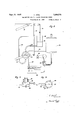
Figs. 3, 4, 5 and 6 are detail views of the steerin mechanism.
Fig. shows a diagram of the current connections.
Fig. shows a hydraulic control arrangement.
Figs. 9 and 10 are detail views of the control arrangement according to Fig. 8.
The devices according to the present invention perform alternating and quite different mechanical works which are controlled by a person. The object of the present construction is to multiply the force of a man and perform different kinds of mechanical worksv which otherwise have to be performed by formed are digging, pile-driving, dredging, loading of freight, roadand railwa construction, cutting of trees, clearance o land, sawing, carrying of goods, lifting and in fact any kind of heavy work.
The device is constructed for instance in the shape of a kneeling man, because in such manner the control and operation of the device is most simple for the operator.
ing the upper part of the bod to which are pivoted two arms. The hea enclosing the control-space 56 is arranged on the upper part of the body 55 and contains a seat 57 for the operator. The control device comprises two arms each of which consists of the upper arm 58a and thel forearm 58h, provided with joints 58c at the elbow and 58d at the shoulder. The operator inserts his arms in hoops of leather or the like secured to the controlarms and places his head between two control-levers 59 and 59h. The operator places further his feet onto two drums 60a and 60h, which are rotatable independentfrom one another. The upper part 55 of the body is hand. The principal kinds of work to be .per
The device consists of a frame form-v 55 The currenteontrol is located in the con- I Vtrol-space 56. If the operator desires to move the apparatus forwardly, he rotates with his legs one of the drums for instance the drum forwardly. Current is sup lied w to the foot-drum 60 (Figs. Sand 4) an 60h by means of collector rings 66 and 67 and flows. into concentric segment- shaped collector rings 68, 69, each of which isprovided with a ole in the middle of the curve. A @5 contact disk 7 0 (Fig. y4) for the drum 60 and a disk 7 0b for the drum 60b both in the shape of chain wheels are mounted freely rotatable on the shaft and are yieldingly pressed against the sidesfof the corres onding seg- 70 ments 68, 69. Each contact dis is provided with contact- levers 71, 72 vwhich are connected with collector rings 71 and 72. From here the current passes by way of the sliding brushes 76, 76 to the electromotor 64 (Figs. 75
1, 7). The latter is without current, if the two drums 602.60b and disks 7 0, 70" are in such position with respect to one another (Fig. 3), that the appropriating contacts 71, 72 just pass into the holes between the halves 80 of the segments 68, 69. If the operator turns forward one of the drums for instance the drum 60, the segments 6 8, 69 are displaced and the levers 71, 72 collect current from the segments 68, 69, the motor starts to rotate and the whole apparatus moves forward. The arrangement is such, that the forward movement of the driving wheel of the caterillar drive is transmitted back to the wheel Oa by means of chains 73. Thereby the wheel 70 together with its contact- levers 71, 72 move after the holes between the halves of the segments 68, 69 until they overtake them, whereby the current is interrupted. If the drum is rotated backward, the poles and thus the current-supply to the motor 64 are changed, so that the ap aratus moves backward. As already mentioned two caterpillar drives. and two foot'drums 60B and 60b are provided. The device moves forward or backward straight or in a curve by operating the one or the other drive in the d esired direction or by simultaneously operating both caterpillar drives.
If the operator intends to rotate the upper part of the body with respect to the bottom art thereof, he inclines his head and there- E presses the control-levers 59 or 59b against the contacts I or II (Figs. 1, 7) whereby the motor 77 is supplied with current. The toothed wheel 78 of this motor meshes with the toothed wheel 7 9, the boss of which is fixed to the upper part of the body. The upper part of the body with its rotating d1sk 80 turns to the right or left hand side according to the inclination of the operators head to the right'or left hand side. The extent of rotation depending on the length of time during which the operator inclines his head.
The following arrangement serves for operating the arms. As shown in Figs. 1 and 2, each arm consists of an upper arm 2 and a forearm 3.
The upper arm 2 is driven from the motor 87 by means of a worm gear 88, the forearm 3 from the motor 89 by means of a worm gear 90. In the shoulder-joint, the whole arrangement can be rotated round the pivots 81 out of the plane of the upper arm and forearm. This can be accomplished by means of a worm gear 82 operated by the motor 83 as illustrated in Fig. 1. Two small control arms 58", 58b corresponding to the two large working arms 2, 3 and connected by a link 58 are arranged in the operating space 56. In the shoulder joints 58d contact disks 86 are arranged of the same'kind as illustrated by Figs. 3 and 4, but each disk 86 is provided with two pairs of interrupted segments 110, 111 and 112, 113. The segments 110, 111 serve for steering the forearm (motor 89), the se ments 112, 113 for steering the upper arm (gmotor 87). A contact-lever 91, controlled bythe steering lever 58b makes contact with the segments 110, 111, a contactlever 91", controlled by the steering lever 58, with the segments 112, 113. Each of these contact levers 91, 91EL is mounted to rotate freely and independently from the other lever on the shoulder joint 58d. the space 56 moves his arm, to the operating lever 58, 58b he connects by means of the contact- levers 91 or 91"L the corresponding motor 87 or 89 in such a manner (Figs 5 and 6), that the corresponding arms 2, 3 of the device carry out the same movements as the operator. Thus in the operating space an inner steering mechanism is provided which in size is reduced with respect to the larger outer working mechanism. The contact-disks are rigidly coupled with the working .mechanism and the current lines are connected to the contacts and motors as illustrated by Fig. 7, so that every movement of the inner steering mechanism is immediwhich is secured If the operator in ately thereafter reproduced in a larger scale and with the required power by the working mechanism and only stopped, when the steering mechanism displaced from its inactive in the required steering position b the movements of the corresponding wor ing mechanism is moved back in its inactive initial position. If the arrangement, according to which a single person can control 50, 100 or more horse-powers, is provided in the hand 4 with removable means for holding dierent tools or is furnished with a wrist-j o int, which imparts to the hand 4 a greater freedom of movement, it will be readily seen that also these arrangements can be operated readily according to the present invention.
The power transmission may be carried out also in other ways for instance. by means of gear wheels from a single motor and transmitted to all mechanisms by means of couplings, which may be controlled for instance by magnets. If desired, the couplings may be operated direct by the corresponding operating lever.
Finally it is remarked, that the gear wheels or worm gears may be replaced by hydraulic or pneumatic power transmission means. Figs. 8, 9 and 10 show diagramma-tically an arm, which is operated by hydraulic pressure. By means of a rod 94, the arm 92 is pivotally connected with the piston 96 operating in a cylinder illed with liquid. The arm 92 is connected by the rod 97 with a disk-shaped slide valve 98, which is rotatabl mounted in a bearing 99. A disk is tted tightly to the valve 98 and rotates independently about the axis of the valve 98. The disk 100 terminates in an operatin arm 93. The tubes pass into the slide va ve 98, one tube 101 communicating with a pressure tank 103, while the other tube 102 passes into a tank 104. A motor 105 operates the pump 106 and causes a pressure in the tank 103, which represents the owerreceptacle, su plying all pressure cy inders by means of t ie pressure-pipe 101. The operating levers 93 control, by means of the slide valves 98, 100, the supplyv and discharge of the liquid pressure into the working cy inder 95. The channels in the slide valve 98 and the sickle-sha ed channels in the valve disk 100 are readily shown in Fig. 8. Fig. 9 shows the valve in plan view, and Fig. 10 illustrates the same in the operative position. Figs. 8 and 9 show the valve in the inoperative position in which the pipes 101 and 102 are closed by the tightly fitting arts between the sickle-shaped channels of the disk 100.
The operating lever 92 has to take up a parallel position with respect to the control if the latter is moved into the position shown in dotted lines in Fig. 8. This -is carried out also in that, in view of the position between the slide valve and its disk,
ltd
ilu
the liquid passes by way of the pipe 101 into the channel 107 and from here by way of the pipe 109 into the cylinder 95 above the piston 96. Thereby. the latter is forced down and the liquid passes by way of the pipe'110 into the valve-channel 108 and iinally flows by way of the pipe 102 into the tank 104. The flow of liquid takes place until the operating lever '92 has come into the position corresponding to the position of the lever 93. Whenever this has taken place the lever 92 is locked in position by the rod 97.
The working lever follows in the opposite position if the operating lever is moved in the opposite direction.
An arrangement with hydraulic operating means in the shape of pressure-cylinders results in a system of pressure-pipes and discharge pipes, of which theV operating valves are arranged in the operating space.
If, in the case of large constructions, the manual operation of the valves is diiiicult, the same can be carried by motors or in an electromagnetic manner, c. g. the operator has to operate the contacts only, by which the current circuits of the motors or the exciting current of the relays are influenced, which control the operating ,valves 1. Device for performing mechanical works of any kind, comprising a body, at least two arms (upper arm and forearm), a link connecting these arms with one another and a second link for pivotally mounting both arms together on the upper body of the device, power driving means for the two arms and two steering devices for the power driving means, one of which by displacement from its normal position steering the turning of both arms together on the body of the device, the other by displacement from its normal position steering the turninvr of the forearm about the link, connecting the forearm with the upper arm.
2. Device for performing mechanical works of any kind, comprising' a body, at least two arms (upper arm and forearm), a link connecting these arms with one another and a second link for pivotally mounting both arms together on the upper' body of the device, power driving means for the two larms and two steering devices for the power driving means, one of which by displacement from its normal position steering the turn-- ing of both arms together on the body of the device, the other by displacement from its normal position steering the turning of the forearm about the link, connecting the forearm with the upper arm and a preferably mechanical coupling between each ing arm (the pair of arms) has carried-out the movement, corresponding to the initial displacement of the steering device.
3. Device for performing mechanical works of any kind, comprising an upper body and a lower part of the body, means for mounting turnably the upper body on the lower part of the body, a power drive for turning theupper body, at least two arms (upper arm and forearm), a link connecting these arms with one another and a second link for pivotally mounting both arms together on the upper body of the device, power driving means for the two arms and two steering devices for the power driving means, one of which by displacement from its normal position steering the turning of-both arms together on the body of the device, the other-by displacement from its normal position steering the turning of the forearm about the link, connecting the forearm with the upper arm. 1`
4;. Device for performing mechanical works of any kind, comprising a body, at least two arms (upper arm and forearm), a link connecting these arms with one another and a second link for pivotally mounting both arms together on the upper body of the device, power driving means for the two arms and two steering devices for the power driving means, one of which by displacement from its normal position steering the turning of both arms together on the body of the device, the other by displacement from its normal position steering the turning of the forearm about the link, connecting the forearm with the upper arm and a mechanical coupling between each arm and its steering device, which during the action of the power driving means removes the steering device. in its normal (inactive) osition, as soon as .the corresponding arm the pair of arms) has carried out the movement, corresponding to the initial displacement of the steering device, an upper body and a lower part of the body, means for mounting turnably the upper body on the lower part of the body, a power `drive for turning the upper body, a truck on the lower part of the body,
FRANZ l HBL.
arm and its steering device, which during the action of the lpower driving means removes the steering device 1n its normal (1nactive) position, as soon as the correspond
Applications Claiming Priority (1)
| Application Number | Priority Date | Filing Date | Title |
|---|---|---|---|
| AT1880138X | 1929-03-13 |
Publications (1)
| Publication Number | Publication Date |
|---|---|
| US1880138A true US1880138A (en) | 1932-09-27 |
Family
ID=3689206
Family Applications (1)
| Application Number | Title | Priority Date | Filing Date |
|---|---|---|---|
| US435668A Expired - Lifetime US1880138A (en) | 1929-03-13 | 1930-03-13 | Arrangement for performing mechanical works |
Country Status (2)
| Country | Link |
|---|---|
| US (1) | US1880138A (en) |
| FR (1) | FR691927A (en) |
Cited By (57)
| Publication number | Priority date | Publication date | Assignee | Title |
|---|---|---|---|---|
| US2497127A (en) * | 1945-09-13 | 1950-02-14 | Sncase | Aircraft control |
| US2536724A (en) * | 1946-03-07 | 1951-01-02 | Murray G Clay | Unified excavator control system |
| US2618447A (en) * | 1946-09-19 | 1952-11-18 | Sncase | Control device for aircraft |
| US2633669A (en) * | 1949-06-11 | 1953-04-07 | Churus George Par | Movable mechanical figure |
| US2724998A (en) * | 1943-07-20 | 1955-11-29 | Sperry Rand Corp | Positional control apparatus |
| US2742683A (en) * | 1951-07-25 | 1956-04-24 | Junkerather Gewerkschaft | Moulding apparatus |
| US2822094A (en) * | 1953-09-29 | 1958-02-04 | Greer Hydraulics Inc | Bridge manipulator |
| US2858947A (en) * | 1953-11-16 | 1958-11-04 | Garrett Corp | Remote control manipulating apparatus |
| US2861699A (en) * | 1950-10-16 | 1958-11-25 | Gen Mills Inc | Method and apparatus for performing operations at a remote point |
| US3038275A (en) * | 1960-05-24 | 1962-06-12 | Curci Alfred | Self-walking device |
| US3083504A (en) * | 1960-11-15 | 1963-04-02 | Louis M Abbott | Movable figure toy |
| US3087636A (en) * | 1960-10-10 | 1963-04-30 | True Trace Corp | Machine control |
| US3087630A (en) * | 1961-02-10 | 1963-04-30 | Karnow Paul | Omnidirectional manipulator |
| US3093372A (en) * | 1958-10-21 | 1963-06-11 | Cirami Salvatore | Robot amusement ride |
| US3099316A (en) * | 1960-04-25 | 1963-07-30 | Shell Oil Co | Underwater wellhead apparatus and method |
| US3103762A (en) * | 1960-10-17 | 1963-09-17 | Glass | Remotely controlled electric toy |
| US3128575A (en) * | 1959-02-02 | 1964-04-14 | Markes & Co | Toy robot and actuating means therefor |
| US3137501A (en) * | 1961-05-09 | 1964-06-16 | Cirami Salvatore | Coin operated robot ride |
| US3199249A (en) * | 1962-03-12 | 1965-08-10 | Marx & Co Louis | Robot toy and mechanism for actuating the same |
| US3214040A (en) * | 1964-06-24 | 1965-10-26 | William G Willinger | Single lever control for hydraulic backhoes |
| US3493069A (en) * | 1966-09-17 | 1970-02-03 | Zahnradfabrik Friedrichshafen | Dual control system |
| US4095367A (en) * | 1976-06-09 | 1978-06-20 | Takara Co., Ltd. | Articulated robot assembly |
| US4272918A (en) * | 1978-03-30 | 1981-06-16 | Takara Co., Ltd. | Multi-position remote controlling device for toys |
| US4846752A (en) * | 1988-03-18 | 1989-07-11 | Combs Williams M | Remote controlled roller skating toy |
| US5281182A (en) * | 1991-05-15 | 1994-01-25 | Tomy Company, Ltd. | Remote control robot toy with torso and leg twist and torso tilt |
| US5282460A (en) * | 1992-01-06 | 1994-02-01 | Joyce Ann Boldt | Three axis mechanical joint for a power assist device |
| US5320358A (en) * | 1993-04-27 | 1994-06-14 | Rpb, Inc. | Shooting game having programmable targets and course for use therewith |
| US6312398B1 (en) * | 1996-12-26 | 2001-11-06 | The United States Of America As Represented By The Administrator Of The National Aeronautics And Space Administration | Actuator for flexing a resilient covering |
| EP2351632A2 (en) * | 2008-08-23 | 2011-08-03 | In-Sang Kim | Large rideable bipedal walking robot for use as an amusement park ride, and amusement park system using same |
| US20120237319A1 (en) * | 2011-03-17 | 2012-09-20 | Raytheon Company | Robotic Lift Device with Human Interface Operation |
| US20120283746A1 (en) * | 2011-05-02 | 2012-11-08 | Hstar Technologies | Mobile Medical Robotic System |
| WO2012149392A3 (en) * | 2011-04-29 | 2013-01-03 | Ratheon Company | Multi-degree of freedom torso support for a robotic agile lift system |
| US20130145530A1 (en) * | 2011-12-09 | 2013-06-13 | Manu Mitra | Iron man suit |
| US8942846B2 (en) | 2011-04-29 | 2015-01-27 | Raytheon Company | System and method for controlling a teleoperated robotic agile lift system |
| US8977388B2 (en) | 2011-04-29 | 2015-03-10 | Sarcos Lc | Platform perturbation compensation |
| ITAR20130044A1 (en) * | 2013-10-29 | 2015-04-30 | Stefano Bono | DROPPED DOG, PARTICULARLY TYPICAL FOR THE SIMULATION OF A KNIGHT IN A SADDLE OF A BIPEDE ANIMAL. |
| USD747772S1 (en) * | 2012-01-09 | 2016-01-19 | Design Ideas Ltd. | Human model |
| US9616580B2 (en) | 2012-05-14 | 2017-04-11 | Sarcos Lc | End effector for a robotic arm |
| US9789603B2 (en) | 2011-04-29 | 2017-10-17 | Sarcos Lc | Teleoperated robotic system |
| US20200180146A1 (en) * | 2018-12-11 | 2020-06-11 | Ubtech Robotics Corp | Assembly for driving waist of robot and robot having the same |
| US10766133B2 (en) | 2014-05-06 | 2020-09-08 | Sarcos Lc | Legged robotic device utilizing modifiable linkage mechanism |
| US10765537B2 (en) | 2016-11-11 | 2020-09-08 | Sarcos Corp. | Tunable actuator joint modules having energy recovering quasi-passive elastic actuators for use within a robotic system |
| US10821614B2 (en) | 2016-11-11 | 2020-11-03 | Sarcos Corp. | Clutched joint modules having a quasi-passive elastic actuator for a robotic assembly |
| US10828767B2 (en) | 2016-11-11 | 2020-11-10 | Sarcos Corp. | Tunable actuator joint modules having energy recovering quasi-passive elastic actuators with internal valve arrangements |
| US10843330B2 (en) | 2017-12-07 | 2020-11-24 | Sarcos Corp. | Resistance-based joint constraint for a master robotic system |
| US10906191B2 (en) | 2018-12-31 | 2021-02-02 | Sarcos Corp. | Hybrid robotic end effector |
| US10919161B2 (en) | 2016-11-11 | 2021-02-16 | Sarcos Corp. | Clutched joint modules for a robotic system |
| US11241801B2 (en) | 2018-12-31 | 2022-02-08 | Sarcos Corp. | Robotic end effector with dorsally supported actuation mechanism |
| US11331809B2 (en) | 2017-12-18 | 2022-05-17 | Sarcos Corp. | Dynamically controlled robotic stiffening element |
| US11351675B2 (en) | 2018-12-31 | 2022-06-07 | Sarcos Corp. | Robotic end-effector having dynamic stiffening elements for conforming object interaction |
| US11717956B1 (en) | 2022-08-29 | 2023-08-08 | Sarcos Corp. | Robotic joint system with integrated safety |
| US11794345B2 (en) | 2020-12-31 | 2023-10-24 | Sarcos Corp. | Unified robotic vehicle systems and methods of control |
| US11826907B1 (en) | 2022-08-17 | 2023-11-28 | Sarcos Corp. | Robotic joint system with length adapter |
| US11833676B2 (en) | 2020-12-07 | 2023-12-05 | Sarcos Corp. | Combining sensor output data to prevent unsafe operation of an exoskeleton |
| US11897132B1 (en) | 2022-11-17 | 2024-02-13 | Sarcos Corp. | Systems and methods for redundant network communication in a robot |
| US11924023B1 (en) | 2022-11-17 | 2024-03-05 | Sarcos Corp. | Systems and methods for redundant network communication in a robot |
| US12172298B2 (en) | 2022-11-04 | 2024-12-24 | Sarcos Corp. | Robotic end-effector having dynamic stiffening elements with resilient spacers for conforming object interaction |
-
1930
- 1930-03-13 US US435668A patent/US1880138A/en not_active Expired - Lifetime
- 1930-03-13 FR FR691927D patent/FR691927A/en not_active Expired
Cited By (73)
| Publication number | Priority date | Publication date | Assignee | Title |
|---|---|---|---|---|
| US2724998A (en) * | 1943-07-20 | 1955-11-29 | Sperry Rand Corp | Positional control apparatus |
| US2497127A (en) * | 1945-09-13 | 1950-02-14 | Sncase | Aircraft control |
| US2536724A (en) * | 1946-03-07 | 1951-01-02 | Murray G Clay | Unified excavator control system |
| US2618447A (en) * | 1946-09-19 | 1952-11-18 | Sncase | Control device for aircraft |
| US2633669A (en) * | 1949-06-11 | 1953-04-07 | Churus George Par | Movable mechanical figure |
| US2861699A (en) * | 1950-10-16 | 1958-11-25 | Gen Mills Inc | Method and apparatus for performing operations at a remote point |
| US2742683A (en) * | 1951-07-25 | 1956-04-24 | Junkerather Gewerkschaft | Moulding apparatus |
| US2822094A (en) * | 1953-09-29 | 1958-02-04 | Greer Hydraulics Inc | Bridge manipulator |
| US2858947A (en) * | 1953-11-16 | 1958-11-04 | Garrett Corp | Remote control manipulating apparatus |
| US3093372A (en) * | 1958-10-21 | 1963-06-11 | Cirami Salvatore | Robot amusement ride |
| US3128575A (en) * | 1959-02-02 | 1964-04-14 | Markes & Co | Toy robot and actuating means therefor |
| US3099316A (en) * | 1960-04-25 | 1963-07-30 | Shell Oil Co | Underwater wellhead apparatus and method |
| US3038275A (en) * | 1960-05-24 | 1962-06-12 | Curci Alfred | Self-walking device |
| US3087636A (en) * | 1960-10-10 | 1963-04-30 | True Trace Corp | Machine control |
| US3103762A (en) * | 1960-10-17 | 1963-09-17 | Glass | Remotely controlled electric toy |
| US3083504A (en) * | 1960-11-15 | 1963-04-02 | Louis M Abbott | Movable figure toy |
| US3087630A (en) * | 1961-02-10 | 1963-04-30 | Karnow Paul | Omnidirectional manipulator |
| US3137501A (en) * | 1961-05-09 | 1964-06-16 | Cirami Salvatore | Coin operated robot ride |
| US3199249A (en) * | 1962-03-12 | 1965-08-10 | Marx & Co Louis | Robot toy and mechanism for actuating the same |
| US3214040A (en) * | 1964-06-24 | 1965-10-26 | William G Willinger | Single lever control for hydraulic backhoes |
| US3493069A (en) * | 1966-09-17 | 1970-02-03 | Zahnradfabrik Friedrichshafen | Dual control system |
| US4095367A (en) * | 1976-06-09 | 1978-06-20 | Takara Co., Ltd. | Articulated robot assembly |
| US4272918A (en) * | 1978-03-30 | 1981-06-16 | Takara Co., Ltd. | Multi-position remote controlling device for toys |
| US4846752A (en) * | 1988-03-18 | 1989-07-11 | Combs Williams M | Remote controlled roller skating toy |
| US5281182A (en) * | 1991-05-15 | 1994-01-25 | Tomy Company, Ltd. | Remote control robot toy with torso and leg twist and torso tilt |
| US5282460A (en) * | 1992-01-06 | 1994-02-01 | Joyce Ann Boldt | Three axis mechanical joint for a power assist device |
| US5320358A (en) * | 1993-04-27 | 1994-06-14 | Rpb, Inc. | Shooting game having programmable targets and course for use therewith |
| US6312398B1 (en) * | 1996-12-26 | 2001-11-06 | The United States Of America As Represented By The Administrator Of The National Aeronautics And Space Administration | Actuator for flexing a resilient covering |
| EP2351632A2 (en) * | 2008-08-23 | 2011-08-03 | In-Sang Kim | Large rideable bipedal walking robot for use as an amusement park ride, and amusement park system using same |
| EP2351632A4 (en) * | 2008-08-23 | 2013-11-20 | In-Sang Kim | Large rideable bipedal walking robot for use as an amusement park ride, and amusement park system using same |
| US20120237319A1 (en) * | 2011-03-17 | 2012-09-20 | Raytheon Company | Robotic Lift Device with Human Interface Operation |
| US9314921B2 (en) * | 2011-03-17 | 2016-04-19 | Sarcos Lc | Robotic lift device with human interface operation |
| US8977388B2 (en) | 2011-04-29 | 2015-03-10 | Sarcos Lc | Platform perturbation compensation |
| US11865705B2 (en) | 2011-04-29 | 2024-01-09 | Sarcos, Lc | Teleoperated robotic system |
| US8892258B2 (en) | 2011-04-29 | 2014-11-18 | Raytheon Company | Variable strength magnetic end effector for lift systems |
| US8942846B2 (en) | 2011-04-29 | 2015-01-27 | Raytheon Company | System and method for controlling a teleoperated robotic agile lift system |
| WO2012149392A3 (en) * | 2011-04-29 | 2013-01-03 | Ratheon Company | Multi-degree of freedom torso support for a robotic agile lift system |
| US8977398B2 (en) | 2011-04-29 | 2015-03-10 | Sarcos Lc | Multi-degree of freedom torso support for a robotic agile lift system |
| US11745331B2 (en) | 2011-04-29 | 2023-09-05 | Sarcos, Lc | Teleoperated robotic system with payload stabilization |
| US11738446B2 (en) | 2011-04-29 | 2023-08-29 | Sarcos, Lc | Teleoperated robotic system with impact responsive force feedback |
| US9789603B2 (en) | 2011-04-29 | 2017-10-17 | Sarcos Lc | Teleoperated robotic system |
| US9533411B2 (en) | 2011-04-29 | 2017-01-03 | Sarcos Lc | System and method for controlling a teleoperated robotic agile lift system |
| US20120283746A1 (en) * | 2011-05-02 | 2012-11-08 | Hstar Technologies | Mobile Medical Robotic System |
| US20130145530A1 (en) * | 2011-12-09 | 2013-06-13 | Manu Mitra | Iron man suit |
| USD747772S1 (en) * | 2012-01-09 | 2016-01-19 | Design Ideas Ltd. | Human model |
| US9616580B2 (en) | 2012-05-14 | 2017-04-11 | Sarcos Lc | End effector for a robotic arm |
| US10780588B2 (en) | 2012-05-14 | 2020-09-22 | Sarcos Lc | End effector for a robotic arm |
| EP2868357A1 (en) * | 2013-10-29 | 2015-05-06 | Stefano Bono | Self-propelled puppet, particularly of the type for simulating a rider astride a bipedal animal |
| ITAR20130044A1 (en) * | 2013-10-29 | 2015-04-30 | Stefano Bono | DROPPED DOG, PARTICULARLY TYPICAL FOR THE SIMULATION OF A KNIGHT IN A SADDLE OF A BIPEDE ANIMAL. |
| US10766133B2 (en) | 2014-05-06 | 2020-09-08 | Sarcos Lc | Legged robotic device utilizing modifiable linkage mechanism |
| US11772283B2 (en) | 2016-11-11 | 2023-10-03 | Sarcos Corp. | Clutched joint modules having a quasi-passive elastic actuator for a robotic assembly |
| US10828767B2 (en) | 2016-11-11 | 2020-11-10 | Sarcos Corp. | Tunable actuator joint modules having energy recovering quasi-passive elastic actuators with internal valve arrangements |
| US11981027B2 (en) | 2016-11-11 | 2024-05-14 | Sarcos Corp. | Tunable actuator joint modules having energy recovering quasi-passive elastic actuators with internal valve arrangements |
| US11926044B2 (en) | 2016-11-11 | 2024-03-12 | Sarcos Corp. | Clutched joint modules having a quasi-passive elastic actuator for a robotic assembly |
| US10919161B2 (en) | 2016-11-11 | 2021-02-16 | Sarcos Corp. | Clutched joint modules for a robotic system |
| US10765537B2 (en) | 2016-11-11 | 2020-09-08 | Sarcos Corp. | Tunable actuator joint modules having energy recovering quasi-passive elastic actuators for use within a robotic system |
| US11759944B2 (en) | 2016-11-11 | 2023-09-19 | Sarcos Corp. | Tunable actuator joint modules having energy recovering quasi- passive elastic actuators with internal valve arrangements |
| US10821614B2 (en) | 2016-11-11 | 2020-11-03 | Sarcos Corp. | Clutched joint modules having a quasi-passive elastic actuator for a robotic assembly |
| US10843330B2 (en) | 2017-12-07 | 2020-11-24 | Sarcos Corp. | Resistance-based joint constraint for a master robotic system |
| US11331809B2 (en) | 2017-12-18 | 2022-05-17 | Sarcos Corp. | Dynamically controlled robotic stiffening element |
| US20200180146A1 (en) * | 2018-12-11 | 2020-06-11 | Ubtech Robotics Corp | Assembly for driving waist of robot and robot having the same |
| US10888993B2 (en) * | 2018-12-11 | 2021-01-12 | Ubtech Robotics Corp | Assembly for driving waist of robot and robot having the same |
| US11679511B2 (en) | 2018-12-31 | 2023-06-20 | Sarcos Corp. | Robotic end effector with dorsally supported actuation mechanism |
| US11351675B2 (en) | 2018-12-31 | 2022-06-07 | Sarcos Corp. | Robotic end-effector having dynamic stiffening elements for conforming object interaction |
| US11241801B2 (en) | 2018-12-31 | 2022-02-08 | Sarcos Corp. | Robotic end effector with dorsally supported actuation mechanism |
| US10906191B2 (en) | 2018-12-31 | 2021-02-02 | Sarcos Corp. | Hybrid robotic end effector |
| US11833676B2 (en) | 2020-12-07 | 2023-12-05 | Sarcos Corp. | Combining sensor output data to prevent unsafe operation of an exoskeleton |
| US11794345B2 (en) | 2020-12-31 | 2023-10-24 | Sarcos Corp. | Unified robotic vehicle systems and methods of control |
| US11826907B1 (en) | 2022-08-17 | 2023-11-28 | Sarcos Corp. | Robotic joint system with length adapter |
| US11717956B1 (en) | 2022-08-29 | 2023-08-08 | Sarcos Corp. | Robotic joint system with integrated safety |
| US12172298B2 (en) | 2022-11-04 | 2024-12-24 | Sarcos Corp. | Robotic end-effector having dynamic stiffening elements with resilient spacers for conforming object interaction |
| US11897132B1 (en) | 2022-11-17 | 2024-02-13 | Sarcos Corp. | Systems and methods for redundant network communication in a robot |
| US11924023B1 (en) | 2022-11-17 | 2024-03-05 | Sarcos Corp. | Systems and methods for redundant network communication in a robot |
Also Published As
| Publication number | Publication date |
|---|---|
| FR691927A (en) | 1930-10-28 |
Similar Documents
| Publication | Publication Date | Title |
|---|---|---|
| US1880138A (en) | Arrangement for performing mechanical works | |
| US2494324A (en) | Road grader | |
| US5553992A (en) | Controls for a skid steer loader | |
| US3792744A (en) | Drive control apparatus for vehicles | |
| US3637036A (en) | Hydrostatic drive system | |
| US2903949A (en) | Helve action telescoping boom compactor | |
| US2766834A (en) | Valve for simultaneous or selective control of mower traction motors | |
| CA1058484A (en) | Skid-steered tractor vehicle combined steering lever and auxiliary control with self-centering mechanism | |
| US2954092A (en) | Mobile boom-supported platform | |
| US3186015A (en) | Street sweeper | |
| US3938401A (en) | Two-speed motor control for dual hydrostatic transmissions | |
| US3063173A (en) | Self-loading carry-all | |
| US4274796A (en) | Machine comprising a rotatable boom assembly | |
| US3319817A (en) | Self-propelled loader | |
| US2732022A (en) | Steering control means for electric | |
| US3782488A (en) | Control system for differential hydrostatic steering | |
| US2557066A (en) | Tractor-trailer steering apparatus | |
| US3567051A (en) | Greatly maneuverable self-propelled machine | |
| US3616477A (en) | Power driven road sweeper with laterally and angularly adjustable brush | |
| US2587969A (en) | Motor-driven cutting and breaking machine | |
| US2380619A (en) | Steering mechanism for tractor cranes | |
| US3563319A (en) | Pin-driving and pulling machine | |
| US3581497A (en) | Control apparatus for hydraulic drive mechanism | |
| US2421139A (en) | Dual steering mechanism | |
| US3968706A (en) | Two-speed motor control for dual hydrostatic transmissions |