US1862012A - Weighing scale - Google Patents
Weighing scale Download PDFInfo
- Publication number
- US1862012A US1862012A US353349A US35334929A US1862012A US 1862012 A US1862012 A US 1862012A US 353349 A US353349 A US 353349A US 35334929 A US35334929 A US 35334929A US 1862012 A US1862012 A US 1862012A
- Authority
- US
- United States
- Prior art keywords
- frame
- rollers
- scale
- indicator
- load
- Prior art date
- Legal status (The legal status is an assumption and is not a legal conclusion. Google has not performed a legal analysis and makes no representation as to the accuracy of the status listed.)
- Expired - Lifetime
Links
Images


Classifications
-
- G—PHYSICS
- G01—MEASURING; TESTING
- G01G—WEIGHING
- G01G1/00—Weighing apparatus involving the use of a counterweight or other counterbalancing mass
Definitions
- This invention relates to springless weighing scales.
- The'objec t is to provide a novel counterbalancing system which will provide the maximum Weighing capacity for a given movementof the scale beam.
- the object is to provide novel means for multiplying the movement of an indicator from a counter-balancing system.
- the object is to provide a counterbalancing system consisting of a plurality-ofweightedrollers interconnected for movement along a fixed frame.
- Another-object is tO-IJIOVlClQ novel sealing meansfor the scale.
- Still another object is'to provide a novel connection" between the counterbalancing system andthe indicator for driving the latter.
- FIG. 1 is a-front view of the upper portion of thescaleg' Fig.2 is an enlarged detail view of the counter-balancing mechanism Fig; 3 is a section 'on line 33 of Fig. 2;
- Fig. t is a viewtaken from the right side of Fig.3,and;
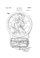
- the scale comprises a housing 10 provided with a dial chart llcoacting with a pointer 12.
- the latter is carried by a shaft -3 journalled in crosspieces 14 extending across a rectangular, stationary frame 15.
- This frame supports the counterbalancing system (Figs. 2 and 3) consistingof eight counter'weights, in the-form of rollers, for counterbalancing the weight of a load on the platform (not shown).
- rollers 16 and 17 on one side of the frame 15 and rollers 18 and 19 on the other side of the frame is a movable oblong frame 25 which constralns the rollers to movement in a vertical direction only.
- the rollers are flanged at both sides, the inner flanges coacting with the movable frame-.25 and the outer flanges with the fixed frame 15 whereby axial movement of the rollers is also prevented.
- Each of the rollers has a tape connecting it with the movable frame 25, tapes 26, 27, 28,
- the usual tare beams 35 are rigidly attached to the lever 33.
- the latter is pro-* vided with a second knife edge engaged by i a link 37 having a pivoted connection with the draft rod 38 connected to the base levers (not shown).
- Thelatter through its connection with i 33 countercloclnvise and pulls down on tape cam 30 rotates the shaft 16 counterclockwise.
- the rollers 16 thereupon wind up tape 20 and through tapes 26 lift frame 25 and rotate rolls 17, 18, and 19 to wInd up their respective.
- the frame 25 in rising actuates the indicator shaft-13 in the following manner.
- a bail 40 Pivoted between the sides of frame 25 is a bail 40, the horizontal arm of which has the upper end-of a tape 41 attached thereto.
- the tape is wound once about the periphery of a drum 42 and then fixed thereto.
- a second tape &3 is fixed to said drum at a point spaced from the tape 41.
- the lower end of tape 431s fixed to an arm pivoted to the frame 25 and biased downwardly by a weight 46 adjustably threaded on an extension of said arm.
- the effect of arm 45 is to keep tapes 41 and 3 43 taut and prevent overthrow of the drum 5 of the indicator throughout its travel the frame 15 has rigidly fastened thereto 'apair of rods 48 (see Fig.
- a threaded rod 50 is carried and held against rotation by lock nuts 51.
- Rotatably mounted on the rod 50 are a pluralIty of thin sealing plates 52 having a rounded cam portion 53 at the left (as viewed in Fig. 5) and a handle portion 54 at the right.
- the cam portion is designed to engage a roller 56 mounted on ball hearings on a stud 57 carried between the sides of vertical depending arms 58 comprising an integral part of bail 40.
- a threaded rod 59 fixed to the bail and upwardly extending therefrom adjustabiy carries a weight 60 which is adjusted to cause roller 56 to lightly contact the cam portions 53 of sealing plates 52.
- anyone of the plates 52 may take either the position shown in full lines in Fig.
- the plates can be adjusted to give the desired motion to the indicator at all points of its travel. After they have been so ad- ]usted they are clamped in position on rod 52 by tightening nuts 51.
- the operation of the scale is as follows: When a load is placed on the platform (not shown) the rod 88 is pulled downwardly rocking the lever 33 counterclockwise and pulling down on tape 31. The latter rocks the shaft 16 on which rollers 16 are fixed and through the tapes 26 connected to these rollers lifts frame 25 which in turn lifts rollers 17, 18, and 19. The extreme upper position of the rollers and frame 25 is shown in dotted lines in Fig. 2. The frame 25 carrfes with it the bail 40 which through tapes 41 and 43 rotates the drum 42 and shaft 13 to which indicator 12 is fixed.
- cam 80 is to vary the moment arm of the applied load whereby movement of the counterbalancing mechanism is adapted to vary in accordance with the load. If the moment arm of the applied load were constant, the weight and moment arm of the rollers and frame 25 being fixed, the application of any load would overbalance the rollers and frame to the limit of thel r movement. This can easily be understood by comparing the moment arm of the load to one side of a lever and the moment arm of the counterbalances to the other arm of the lever. If the moments of a lei er are equal, an additional load on one arm will completely overbalance the other arm. By decreasing one of the moment arms as the load thereon is increased, the moment equal to the product of said load by said arm remains the same. The decreasing moment arm in the present construct'on is obtained by the use of eccentric 80.
- the invention permits the use of four counterbalancing weights including a frame providing an evenly distributed counterbalancing system.
- the equal distribution of the counterbalances on both sides of frame 25 neutralizes any tendency to errors due to placing the scale out of level.
- a stationary frame a counterbalancing system movable along said frame, a movable frame guided for movement through free, slidable engagement with the counterbalancing system and actuated by said counterbalancing system, an indicator driven by said movable frame, and means for actuating said counterbalancing system.
- a stationary frame load resistant members comprising rollers guided for rolling movement along said frame, a movable frame guided for movement and actuated by said rollers, an indicator element mounted on said stationary frame and actuatable by said movable frame, and means for actuating said rollers.
- a stationary frame In a scale, a stationary frame, a counterbalanci-ng system supported “by said frame, means for actuating said system, a movable frame actuated by said system, an indicator, connections from said movable frame to said indicator for driving the latter, sealing means carried by said stationary frame, and means carried by said connections exterior to said movable frame for engaging said sealing means to vary the movement of the indicator.
- a stationary frame a counterbalancing system supported thereby, an indicator mounted on said frame, means actuated by said system for driving said indicator, and a cam adjustable as to contour carried by said frame and engaging said means for controlling the effect of said means on said indicator.
- a stationary frame a counterbalancing system supported thereby, an in dicator mounted on said frame, means actuated by said system for driving said indicator, and a plurality of individually adjustable cam elements carried by said frame for engaging said means and controlling the effect of said means on said indicator.
- a stationary frame a counterbalancing system supported thereby, a movable frame guided for movement in a vertical direction by free, slidable engagement
- an indicator a drum carried by said stationary frame for driving said indicator, and a tape connecting said drum to said movable frame whereby the indicator drum and indicator are actuated upon movement of said movable frame.
- a scale beam a stationary frame, a plurality of counterbalancing rollers guided for movement along said frame, means for driving one of said rollers from said beam, and means actuated by said latter roller for actuating the remaining rollers.
- a stationary frame a plurality of counterbalancing rollers, tapes for suspending said rollers from said frame, a
- cam carried by one of said rollers, a scale beam, a connection from the scale beam to the cam for driving the roller carrying said cam, and means actuated from said cam-carrying roller for actuating the remaining rollers.
- a stationary frame a plurality of vertically spaced counterbalancing rollers, tapes attached to said frame for sus- 1 pending said rollers therefrom, an indicator element carried by said frame,-and means connecting said rollers'to each other and to said indicator'for actuating the latter;
- rollers engaging saidframe 'at' opposite sidesthereof to guide it for vertical movement.
- said movable frame having a tape connectedthereto and to said-indicator element foractuating the latter.
- rollers having.fla'nges'engaging the movable and stationary frames for guiding the rollers along said frames.
- 'A sea-ling device for scales comprising a plurality of elements formed with cam por tions,-a rod on which said elements are rotatably mounted one above the other,:and clamping means on said rod for clamping the'elements against movement on the rod;
- a load resistant element In a scale, a load resistant element, guides'connected to and engaging andconstraining opposite sides of said element, and load-operated-means for actuating'said element to move it along said guides.
- a plurality of load resistant elements one above the other, guides connected to and engaging and constraining op posite sides'of said element and along which said element is adapted to roll, and load-oper-z ate d meansfor actuating said element to roll italong-said guides.
- a load resistant rolling element guides movable relative to each other for-engaging and constraining opposite sides of said element, a connection between each guide and-said element, and load-actuated means for-moving-said guidesrelatively to roll saidelement along the guides.
- a loadresistant rolling element In a :scale, a loadresistant rolling element, guides engaging and constraining opposite sides of said element, one of the guides being movable and the other relatively fixed, tapes connecting the element to each guide, and load-actuated means for moving said movable guide to roll the element along the guides whereby to unwind from the element the tape connecting the said movable guide and element and to wind up the other tape on the element.
- a scale In a scale, a plurality of load resistant elements, a guide between and in engagement with said elements, load-actuated means for rolling said resistant elements along the 0pposite sides of said guide, and an indicator for indicating the movement of the resistant element.
- load resisting means In a scale, load resisting means, a movable member along which said means is adapted to roll, and load-actuated means movable relative to the member for moving said member to effect rolling of the resisting means along said member.
- an indicator In a scale, an indicator, a shaft on which the indicator is mounted, a member rigid on said shaft, a tape device connected to said member and extending and terminating in opposite directions therefrom, a frame, elements mounted on said frame to be normally freely movable relatively thereto, the elements being on opposite sides of said member and connected to the opposite ends of said tape device, and load-actuated means for operating the frame to actuate the indicator through said tape and elements.
- load resistant means comprising inclividually adjustable elements having cam surfaces cooperating with the indicating means to adjust the movement of the indicating means throughout its entire travel.
- a frame a plurality of load resistant members having a rolling engagement with. said frame, the center of gravity of said members being at the axis of rotation of said members, indicator mechanism controlled by said members, and common actuating means for said members to roll them along the frame, said actuating means including a variable moment arm device for varying the counterbalance action of the rollers in accordance with the magnitude of the load.
- a stationary frame In a scale, a stationary frame, a vertically movable member, rollers between the frame and said member and effectively engaged with the frame and member, means positively connecting the rollers to the frame nature.
Landscapes
- Physics & Mathematics (AREA)
- General Physics & Mathematics (AREA)
- Unwinding Webs (AREA)
Description
June 7, 1932. G|LBERT 1,862,012
WEIGHING SCALE Filed April 8 1929 3 Sheets-Sheet 1 gwwemboz Mom W GILBE WEIGHING SCALE June 1932,-
Filed April 8, 1929 5 Sheets-Sheet 2 -MHWWHWA- n ve nt June 7, 1932. w GlLBERT 1,862,012
WEIGHING SCALE Filed April 8, 1929 3 Sheets-Sheet 5 iii ,5
Patented June 7, 1932 U N! TE;D;...- STAT ES P ATE 65 T F F ICLE' \VILIZIAM.N. GILBERT, OF HUDSON HEIGHTS, NEW JERSEY, ASSIGNOR TO DAYTON SGALE.COMPANY,OF DAYTON, OHIO, A CORPORATION OF NEW JERSEY WEIGHING SCALE Application filed April 8, 1929. Serial No. 353,349.'
This invention relates to springless weighing scales. Y
The'objec t is to provide a novel counterbalancing system which will provide the maximum Weighing capacity for a given movementof the scale beam.
Further, the object is to provide novel means for multiplying the movement of an indicator from a counter-balancing system.
in -Still further, the object is to provide a counterbalancing system consisting of a plurality-ofweightedrollers interconnected for movement along a fixed frame.
Another-object is tO-IJIOVlClQ novel sealing meansfor the scale.
Still another object is'to provide a novel connection" between the counterbalancing system andthe indicator for driving the latter.
Further and-other objects and advantages 1 will be hereinafter set forthin the accompanyingspecification and claims, and-shown in the drawings, which by way of illustration show what is now'consi'dered to be the preferred embodiment of the invention.
In the drawings' I r Fig. 1 is a-front view of the upper portion of thescaleg' Fig.2 is an enlarged detail view of the counter-balancing mechanism Fig; 3 is a section 'on line 33 of Fig. 2;
Fig. tis a viewtaken from the right side of Fig.3,and;
Fig' 5 i's'a detail of the adjustment for a sealing element.
In detail; the scale comprises a housing 10 provided with a dial chart llcoacting with a pointer 12. The latteris carried bya shaft -3 journalled in crosspieces 14 extending across a rectangular, stationary frame 15. This frame supports the counterbalancing system (Figs. 2 and 3) consistingof eight counter'weights, in the-form of rollers, for counterbalancing the weight of a load on the platform (not shown). I The roliers'occur in pairs fixed to opposite ends of horizontal shafts: Rollers 16are thus'fixed to a shaft 16, rollers 17 are fixed to shafti17, rollerst18 to shaft-418 androllers19'toshaft 19-. Each pair'ofr'oilers is suspended from the frame 15 by tapes-1r. Tapes229,-21,.22,-and '23 are thus respectively attached to rollers 16, 17, 18, and
19. \Vhen a 'load'is applied, all .the rollers move up and wind up the aforesaid tapes. Between rollers 16 and 17 on one side of the frame 15 and rollers 18 and 19 on the other side of the frame is a movable oblong frame 25 which constralns the rollers to movement in a vertical direction only. The rollers are flanged at both sides, the inner flanges coacting with the movable frame-.25 and the outer flanges with the fixed frame 15 whereby axial movement of the rollers is also prevented.
Each of the rollers has a tape connecting it with the movable frame 25, tapes 26, 27, 28,
and 29 thus respectively connecting rollers Y which is attached the upper end of a tape 31.
The lower end of tape 31 is fastened to a link I 32 having a pivotal connection with a lever= 33 pivoted to the scale frame by a knife edge 34. The usual tare beams 35 are rigidly attached to the lever 33. The latter is pro-* vided with a second knife edge engaged by i a link 37 having a pivoted connection with the draft rod 38 connected to the base levers (not shown). Thus when a load is applied to the scale the base levers cause downward movement of the draft rod which rocks lever S5 31. Thelatter through its connection with i 33 countercloclnvise and pulls down on tape cam 30 rotates the shaft 16 counterclockwise. The rollers 16 thereupon wind up tape 20 and through tapes 26 lift frame 25 and rotate rolls 17, 18, and 19 to wInd up their respective.
tapes attached to frame15.
The frame 25 in rising actuates the indicator shaft-13 in the following manner. Pivoted between the sides of frame 25 is a bail 40, the horizontal arm of which has the upper end-of a tape 41 attached thereto. The tape is wound once about the periphery of a drum 42 and then fixed thereto. A second tape &3 is fixed to said drum at a point spaced from the tape 41. The lower end of tape 431s fixed to an arm pivoted to the frame 25 and biased downwardly by a weight 46 adjustably threaded on an extension of said arm. The effect of arm 45 is to keep tapes 41 and 3 43 taut and prevent overthrow of the drum 5 of the indicator throughout its travel the frame 15 has rigidly fastened thereto 'apair of rods 48 (see Fig. Rigidly fixed to the rods 48 are plates 49 between which a threaded rod 50 is carried and held against rotation by lock nuts 51. Rotatably mounted on the rod 50 are a pluralIty of thin sealing plates 52 having a rounded cam portion 53 at the left (as viewed in Fig. 5) and a handle portion 54 at the right. The cam portion is designed to engage a roller 56 mounted on ball hearings on a stud 57 carried between the sides of vertical depending arms 58 comprising an integral part of bail 40. A threaded rod 59 fixed to the bail and upwardly extending therefrom adjustabiy carries a weight 60 which is adjusted to cause roller 56 to lightly contact the cam portions 53 of sealing plates 52. Anyone of the plates 52 may take either the position shown in full lines in Fig. 5 or the one shown in dotted lines. In the full line position, a plate 52 holds the roller 56 further to the left than in the dotted line position. The position of the roller 56 is a factor in determining the position of the roller 42 and the indicator 12 rigid therewith. Thus if the roller is moved to the right, bail 40 rocks counterclockwise, loosens up on tape 41 and permits arm 45 to draw down on tape 43 rotating drum 42 counterclockwise and "moving the indicator 12 backwards. Obviously then, if the indicator at a particular point in its travel would ordinarily he moved too far by a certain increment of weight, the plates 52 engaging the roller 56 at said point should be moved to dotted line position thereby retracting the indicator.
The plates can be adjusted to give the desired motion to the indicator at all points of its travel. After they have been so ad- ]usted they are clamped in position on rod 52 by tightening nuts 51.
The operation of the scale is as follows: When a load is placed on the platform (not shown) the rod 88 is pulled downwardly rocking the lever 33 counterclockwise and pulling down on tape 31. The latter rocks the shaft 16 on which rollers 16 are fixed and through the tapes 26 connected to these rollers lifts frame 25 which in turn lifts rollers 17, 18, and 19. The extreme upper position of the rollers and frame 25 is shown in dotted lines in Fig. 2. The frame 25 carrfes with it the bail 40 which through tapes 41 and 43 rotates the drum 42 and shaft 13 to which indicator 12 is fixed.
The purpose of cam 80 is to vary the moment arm of the applied load whereby movement of the counterbalancing mechanism is adapted to vary in accordance with the load. If the moment arm of the applied load were constant, the weight and moment arm of the rollers and frame 25 being fixed, the application of any load would overbalance the rollers and frame to the limit of thel r movement. This can easily be understood by comparing the moment arm of the load to one side of a lever and the moment arm of the counterbalances to the other arm of the lever. If the moments of a lei er are equal, an additional load on one arm will completely overbalance the other arm. By decreasing one of the moment arms as the load thereon is increased, the moment equal to the product of said load by said arm remains the same. The decreasing moment arm in the present construct'on is obtained by the use of eccentric 80.
The invention permits the use of four counterbalancing weights including a frame providing an evenly distributed counterbalancing system. The equal distribution of the counterbalances on both sides of frame 25 neutralizes any tendency to errors due to placing the scale out of level.
While there has been shown and described and pointed out the fundamental novel features of the invention as applied to a single modification it will be understood that various omissions and substitutions and changes in the form and details of the device illustrated and in its operation may be made by those skilled in the art without departing from the spirit of the invention. It is the intention therefore to be limited only as indicated by the scope of the following claims:
1.. In a scale, a stationary frame, a counterbalancing system movable along said frame, a movable frame guided for movement through free, slidable engagement with the counterbalancing system and actuated by said counterbalancing system, an indicator driven by said movable frame, and means for actuating said counterbalancing system.
2. In a scale, a stationary frame, load resistant members comprising rollers guided for rolling movement along said frame, a movable frame guided for movement and actuated by said rollers, an indicator element mounted on said stationary frame and actuatable by said movable frame, and means for actuating said rollers.
3. In a scale, a stationary frame, a counterbalancing system movable along said frame. a movable frame guided for movement and actuatedvby." sa-idrounterbalancing system, :an indicator :driven; by said movable' frame, meansocarried by said stationary frame for adjusting. the 'efiectrof said movable:frame-on said indicatorgaand means for actuating said counterbalancing :syste'm'; H
4. In a scale, a stationary frame, a counterbalanci-ng system supported "by said frame, means for actuating said system, a movable frame actuated by said system, an indicator, connections from said movable frame to said indicator for driving the latter, sealing means carried by said stationary frame, and means carried by said connections exterior to said movable frame for engaging said sealing means to vary the movement of the indicator.
5. In a scale, a stationary frame, a counterbalancing system supported thereby, an indicator mounted on said frame, means actuated by said system for driving said indicator, and a cam adjustable as to contour carried by said frame and engaging said means for controlling the effect of said means on said indicator.
6. In a scale, a stationary frame, a counterbalancing system supported thereby, an in dicator mounted on said frame, means actuated by said system for driving said indicator, and a plurality of individually adjustable cam elements carried by said frame for engaging said means and controlling the effect of said means on said indicator.
7. In a scale, a stationary frame, a counterbalancing system supported thereby, a movable frame guided for movement in a vertical direction by free, slidable engagement With said counterbalancing system and actuated thereby, an indicator, a drum carried by said stationary frame for driving said indicator, and a tape connecting said drum to said movable frame whereby the indicator drum and indicator are actuated upon movement of said movable frame.
8. In a scale such as described in claim 7, and means for holding said tape taut at all times.
9. In a scale, a scale beam, a stationary frame, a plurality of counterbalancing rollers guided for movement along said frame, means for driving one of said rollers from said beam, and means actuated by said latter roller for actuating the remaining rollers.
10. In a scale, a stationary frame, a plurality of counterbalancing rollers, tapes for suspending said rollers from said frame, a
cam carried by one of said rollers, a scale beam, a connection from the scale beam to the cam for driving the roller carrying said cam, and means actuated from said cam-carrying roller for actuating the remaining rollers.
11. In a scale, a stationary frame, a plurality of vertically spaced counterbalancing rollers, tapes attached to said frame for sus- 1 pending said rollers therefrom, an indicator element carried by said frame,-and means connecting said rollers'to each other and to said indicator'for actuating the latter;
12. In a scale, a stationary frame, counterbala-ncingyrollers, tapes attached to said.
frame,ueach =tape being connected to I a roller for suspending it from said'frame, an indi cator element, a movableframe for actuating said element, tapes attached to said movable frame,each tape being sattached to a roller, andnreans for actuating one of said rollers to cause actuation of the movable frame,=said frame thereby: serving to actuate the remain.- ing rollers through thetapesattached thereto.
13..In-a scalesuch-as described" in claim 12, said rollers engaging said movable frame to guide its movement. a
14. Ina scalesuch as describedin claim 12, said rollers engaging saidframe 'at' opposite sidesthereof to guide it for vertical movement.
15. In a scale such as described in claim 12, said movable frame having a tape connectedthereto and to said-indicator element foractuating the latter.
16. In a scale such as described in claim 12,said movableframe having means for con stantly keeping said indicator-driving tape taut.
17. In a. scale-such as described in-cla-im 12,.said rollers having.fla'nges'engaging the movable and stationary frames for guiding the rollers along said frames.
18. A sealing :device for scales-comprising a cam and'a handle portion for-rotating said cam, and load indicatingmechanism including an 1 element freely -movable along said cam.
19. 'A sea-ling device for scales comprising a plurality of elements formed with cam por tions,-a rod on which said elements are rotatably mounted one above the other,:and clamping means on said rod for clamping the'elements against movement on the rod;
20. In a scale, a load resistant element, guides'connected to and engaging andconstraining opposite sides of said element, and load-operated-means for actuating'said element to move it along said guides.
21. In a scale, a plurality of load resistant elements, one above the other, guides connected to and engaging and constraining op posite sides'of said element and along which said element is adapted to roll, and load-oper-z ate d meansfor actuating said element to roll italong-said guides.
22. In a scale, a load resistant rolling element, guides movable relative to each other for-engaging and constraining opposite sides of said element, a connection between each guide and-said element, and load-actuated means for-moving-said guidesrelatively to roll saidelement along the guides.
28. :In a :scale, a loadresistant rolling element, guides engaging and constraining opposite sides of said element, one of the guides being movable and the other relatively fixed, tapes connecting the element to each guide, and load-actuated means for moving said movable guide to roll the element along the guides whereby to unwind from the element the tape connecting the said movable guide and element and to wind up the other tape on the element.
24:. In a scale, a plurality of load resistant elements, a guide between and in engagement with said elements, load-actuated means for rolling said resistant elements along the 0pposite sides of said guide, and an indicator for indicating the movement of the resistant element.
25. In a scale, load resisting means, a movable member along which said means is adapted to roll, and load-actuated means movable relative to the member for moving said member to effect rolling of the resisting means along said member.
26. In a scale, an indicator, a shaft on which the indicator is mounted, a member rigid on said shaft, a tape device connected to said member and extending and terminating in opposite directions therefrom, a frame, elements mounted on said frame to be normally freely movable relatively thereto, the elements being on opposite sides of said member and connected to the opposite ends of said tape device, and load-actuated means for operating the frame to actuate the indicator through said tape and elements.
27. In a scale, load-operated means, an indicator, connections etween the latter and said means including a tape and a member connected to the tape, sealing means, said member freely, movably, engaging said sealing means throughout the entire range of movement of the indicator to adjust the movement of the latter.
28. In a scale, load resistant means, indicating means controlled by the resistant means, and sealing means comprising inclividually adjustable elements having cam surfaces cooperating with the indicating means to adjust the movement of the indicating means throughout its entire travel.
29 In a scale, a frame, a plurality of load resistant members having a rolling engagement with. said frame, the center of gravity of said members being at the axis of rotation of said members, indicator mechanism controlled by said members, and common actuating means for said members to roll them along the frame, said actuating means including a variable moment arm device for varying the counterbalance action of the rollers in accordance with the magnitude of the load.
30. In a scale, a stationary frame, a vertically movable member, rollers between the frame and said member and effectively engaged with the frame and member, means positively connecting the rollers to the frame nature.
WILLIAM N. GILBERT.
Priority Applications (1)
| Application Number | Priority Date | Filing Date | Title |
|---|---|---|---|
| US353349A US1862012A (en) | 1929-04-08 | 1929-04-08 | Weighing scale |
Applications Claiming Priority (1)
| Application Number | Priority Date | Filing Date | Title |
|---|---|---|---|
| US353349A US1862012A (en) | 1929-04-08 | 1929-04-08 | Weighing scale |
Publications (1)
| Publication Number | Publication Date |
|---|---|
| US1862012A true US1862012A (en) | 1932-06-07 |
Family
ID=23388731
Family Applications (1)
| Application Number | Title | Priority Date | Filing Date |
|---|---|---|---|
| US353349A Expired - Lifetime US1862012A (en) | 1929-04-08 | 1929-04-08 | Weighing scale |
Country Status (1)
| Country | Link |
|---|---|
| US (1) | US1862012A (en) |
-
1929
- 1929-04-08 US US353349A patent/US1862012A/en not_active Expired - Lifetime
Similar Documents
| Publication | Publication Date | Title |
|---|---|---|
| US1862012A (en) | Weighing scale | |
| US2244621A (en) | Weighing scale | |
| US1806741A (en) | Spring scale | |
| US2395784A (en) | Weighing apparatus | |
| US3358784A (en) | Precision weigh scales with commonly-controlled taring and zeroizing means | |
| US2633350A (en) | Weighing scale pendulum | |
| US2040071A (en) | Electrically controlled weight indicating mechanism for weighing scales | |
| US1576948A (en) | Scale | |
| US1872420A (en) | Counterbalancing and indicating mechanism for weighing apparatus | |
| US1764274A (en) | Balancing mechanism | |
| US3631935A (en) | Constant meshing force rack and pinion for weigher | |
| US3580095A (en) | Constant meshing force rack and pinion | |
| US1914985A (en) | Testing device | |
| US2835129A (en) | Spring testing device | |
| US1608190A (en) | Weighing scale | |
| US2039528A (en) | Scale | |
| US1564387A (en) | Automatic weighing mechanism | |
| US2124357A (en) | Scale and indicator operating means therefor | |
| US2458704A (en) | Spring testing scales | |
| US2016714A (en) | Scale | |
| US2518585A (en) | Weighing scale indicator drive | |
| US1880651A (en) | Weighing scale | |
| US1656454A (en) | Computing scale | |
| US1869740A (en) | Looze vennootschap maatschappij tot vervaardiging van snijmachines | |
| US1167974A (en) | Scale. |