US1733328A - Stitching machine - Google Patents
Stitching machine Download PDFInfo
- Publication number
- US1733328A US1733328A US224193A US22419327A US1733328A US 1733328 A US1733328 A US 1733328A US 224193 A US224193 A US 224193A US 22419327 A US22419327 A US 22419327A US 1733328 A US1733328 A US 1733328A
- Authority
- US
- United States
- Prior art keywords
- wire
- guide
- cam
- formers
- staple
- Prior art date
- Legal status (The legal status is an assumption and is not a legal conclusion. Google has not performed a legal analysis and makes no representation as to the accuracy of the status listed.)
- Expired - Lifetime
Links
Images


Classifications
-
- B—PERFORMING OPERATIONS; TRANSPORTING
- B27—WORKING OR PRESERVING WOOD OR SIMILAR MATERIAL; NAILING OR STAPLING MACHINES IN GENERAL
- B27F—DOVETAILED WORK; TENONS; SLOTTING MACHINES FOR WOOD OR SIMILAR MATERIAL; NAILING OR STAPLING MACHINES
- B27F7/00—Nailing or stapling; Nailed or stapled work
- B27F7/17—Stapling machines
- B27F7/19—Stapling machines with provision for bending the ends of the staples on to the work
- B27F7/21—Stapling machines with provision for bending the ends of the staples on to the work with means for forming the staples in the machine
Definitions
- This invention relates to certain new and useful improvements in stitching machines. More particularly that type designed for stapling the corners of boxes, and has as a primary object the provision of a simplified machine which will be positive in operation to insure the proper stapling of boxes of difierent sizes.
- Another object of this invention resides in the provision of a machine of the character described in which the saddle or table has improved means of adjustment to accommodate work of various thicknesses.
- Another object of this invention resides in the provision of an improved forming or stapling head in which a single drive shaft is employed to accomplish all of the steps in the operation.
- Another object of this invention resides in the provision of a machine of the character described in which acompound cam actuates the various elements of the stitcher head.
- a further object of this invention resides in the provision of a machine of the character described in which the directors for guiding the staple ends into the work are yieldably urged to their active position so that the driver, in its down stroke, rides onto inclined faces onthe directors to remove them from its path.
- a still further object of this invention resides in the improved means for feeding the wire-to the staple forming mechanism wherein yieldable segments or portions are formed in coacting feed rolls for advancing the wire a predetermined distance each cycle, the rolls having non-engaging portions adapted to slip about the wire during the remainder of the cycle when the staple is being formed.
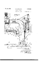
- Figure 1 is a side elevational view, with parts broken away and in section, of a corner stapling machineembodying my invention:
- Figure 2 is an enlarged, detail view, partly in section and partly in side elevation, taken through the outer or working end of the machin5e on the plane of the line 22 of Figure 1
- Figure 3 is a'detail view, partly in section and partly in elevation, taken through the saddle near its inner end and illustrating the clincher and saddle adjusting means;
- Figure 4 is a transverse sectional view, partly in section and partly in elevation. taken throughthe staple forming head on the plane of the line 4-4 of Figure 2;
- Figure 5 is a front elevational view of the outer endot the head and saddle;
- Figure 6 is'a view, partly in section and partly inelevation, taken through the head on the plane of the line 66 of Figure 2;
- Figure 7 is a. perspective view of the staple forming mechanism proper, detached from the stationary guide casing;
- Figure-8 is a perspective view of the staple forminganvil detached from the head
- Figure 9 is a perspective view of the lowfir fdront plate member detached from the Figure -10 is a semi-diagrammatic view, partly in elevation. and partly in section, i1- lustratin'g-the position of the staple form- I ing mechanism at the end of the first step;
- Figure 11 is a view similar to Figure 10 illustrating the parts as about to complete the second step of the operation;
- Figure 12 is a view similar to Figure 10' illustrating the parts'as about to complete the third step; 1
- Figure 13 is a view similar to Figure 10 il- 10o 15 ing unit, designated generally as 13.
- Figure 14 is a fragmentary view, partly in section and partly in elevation, talgen through Figure 5 on the plane of the line l4-14.
- Rod 20 extends downwardly and is directed angularly at a medial point, as at 21, to enter the interior of the standard through an aperture 22, to have its lower end connected with a lever 23, as at 23'.
- lever 23 passes outwardly of the standard through an opening 24 and is fixed to a shaft 25 pivoted in bearings 26 carried by the base and the other end of lever 23 is disposed within the standard and hasone end of a contractile spring 27 connected therewith.
- Spring 27 normally urges rod 20 to its position rendering the clutch 1.9 inoperative and a treadle 28 arranged within convenient reach of an operator working the machine is fixed to shaft 25 so that its depression pulls the rod 20 against its spring to release the clutch mechanism and set the machine in operation.
- a flattened enlargement or boss 29 is formed on the front face of the standard and has a bearing plate 30 secured thereto-by bolts or other means 31, the plate having a pair of spaced lugs or ears 32, between-which the inner end'portion' 33 of a saddle or table 34, to be later described, is pivotally secured by a bolt 35.
- Thesaddle 34 is preferably of cast tubular construction and its top surface is of inverted V-shape to fit the corners of the box B being stitched and its side walls 36 taperingly enlarge from their outer ends toward their inner end portion 37 which extends beneath the pivot bolt 35.
- An adjusting screw 38 threaded into an aperture in the portion 37 to engage an abutment 39 on the adjacent surface of the standard 11, provides means for adjusting the distance between the outer end of the saddle and the lower grooved face of the staple forming unit, to accommodate various thicknesses of material, the
- One side surface of the saddle is provided with grooves or channels 43 and 44 in which stops or guides 45 and 46, respectively, are adjustable, guide 46 providing a support for the outer end portion of the box being stitched and guide 45 a limit or stop.
- a clincher 48 which is held therein by an end plate 49 secured to the extreme end of the saddle by screws or other means 50, the upper end of the clincher being of inverted V-shape to conform with the angle at which the saddle faces are disposed and its'apex 51 is slightly rounded to assure the proper clearance at the box corner.
- the clincher has an opening 52 in which the outer end 53. of a clincher bar 54 pivots, the clincher bar passing through the channel 55 of the saddle and the standard 11 with its rear end 56 connected with an operating means, as later described.
- the clincher bar is medially pivoted on a pin 57 passed through aligned apertures in the sides of the saddle and having its medial portion 59 within the channel 55 of eccentric shape to providean adjustable journal so that rotation of the pivot pin adjusts the uppermost position of the clincher, as later described.
- the rear end 56 of the bar is slotted to receive a bearing block through which a pivot pin 60 passes to connect an operating rod or shaft 61 therewith, the shaft or rod being guided in bearings 62 formed at opposite ends of a spring housing 63, secured to the rear side of the standard and in which is confined an expansile spring 64 coiled about the rod and compressed between the'lower bearing 62 and a pin 65 passed through the shaft.
- the upper end of the rod or shaft has a roller 66 journalled therein which tracks on a collar 67 fixed to the shaft 18 between the clutch mechanism 19 and a hearing 68 for the shaft rear end.
- the shaft 61 is adapted to be actuated against its spring by a hump or cam portion 69 on the collar 67 to move the outer free end of the clincher bar upwardly and with it the clincher to its position illustrated in Figure 13, as will be moreat length described, spring retracting the clincher to its posit1on illustrated in Fi res 10, 11 and 12 when the roller 66 ri es of! the hump or cam.
- the shaft 18 is journaled at its rear end in the bearing 68 and at its forward end in a bearing 70 carried by a mounting plate or support 71 secured to the outer end of the horizontal arm 12 by screws or other means 72. there being suitable provision for lubricating the shaft bearings.
- the shaft 18 projects through the upper portion 73 of plate 71 and a portion 74 of rectangular shape extends downwardly from the plate upper end and has a block or compound guide member 75 secured thereto by bolts or other means 76, the block 75 forming the guide for the staple forming and driving mechanism proper, to be later described.
- the side of the upper portion 73 of the plate has a lateral projection 77 as best shown in Figure 5, and a peripheral flange or wall 78 surrounds the marginal edges of the upper portion of the plate to, with a cover 79 of a shape substantially conforming with that of the plate 71, provide a housing for the entire staple forming and driving mechanism.
- the cover 79 having a hinge mounting 80.
- the forward end 81 of the shaft projects into the space defined by the wall 78 and has a cam wheel or disk 82keyed thereto which has cam.
- grooves 83 and 84 in its opposite faces for operating the staple forming and driving mechanism later described:
- a gear 85 is fixed to the rear face of wheel 82 and meshes with a gear 86 fixed to a wire feed roll 87 journaled on a counter shaft 88 mounted in the plate projection 77, of the plate 71, the wire feed roll 87 cooperating with a second feed roll 89 fixed on the extreme forward end of the shaft 18 outwardly of wheel 82.
- the feed roll 87 has one side slotted, as at 90, see Figure 5 to receive a floating segment 91 which is mounted in the slot and there secured by pins 92 and 93, the opening in the segment through which the pin 93 passes being over size to permit the yieldable prois carried by a reel or drum 99 rotatablymounted from an arm 100 extended upwardly from the late 73 andpasses over a combination gui e and tension member 101 and through a guide tube 102 rovided with means for preventing outwar movement of the wire, and extendin to a point close to the meeting surfaces 0 the rolls 87 and 89, as best shown in Figure 5.
- the wire passes from the feed rolls throu h a tubular guide 103 havingbits outer end ti xed to the stationary guide lock 75 by a bracket member 104 in line with a wire openin in a second guide member 105 longitudina lv adiustably secured inthe lower end portion of the stationary guide or block 75 by a screw member 106 32d a clamping block 107, see Figures 5 and
- the guide 105 has its inner end beveled, as at- 108, and extended into a vertical guide channel 109 within the'stationary guide block 75 to cooperate with a knife 110 to shear the wire, as later described.
- the knife 110 is removably secured to one side of a movable head member 111 by screws or other means 112.
- the member 111 is of elongated rectangular shape and its rear wall, which slides against the surface 113 of the channel 109, is on a plane substantially flush with the outer face of the cam wheel 82 and the upper end of member 111 overlies cam 82 and has a roller 114 tracking within the cam groove 83.
- the lower end of member 1.11 has a boss or enlargement 115 which projects through an elongated opening 116 connecting the guide vgroove or channel 109 with a guide groove or channel 117 in the rear face of the guide block 75, the opening 116 being of a length sufficient to permit the reciprocation of the member 113 by its cam 83.
- the bottom surface of member 111 is of inverted V-shape to correspond with the V of the saddle so that when the member is in its lowermost position it serves to clamp the walls of the box between it and the saddle during the stitching operation.
- the front wall of the member 111 is grooved, as at 118, to mount a vertically slidable driver 119 having its lower end 120 of inverted V-shape to correspond with the V of the saddle, a similar guide groove 121 being formed in the front face of member 111 within the guide groove 118 to receive a driver operating slide 122 which is connected with the driver by screws or other means 123'.
- a pitman 124 having its lower end pivotally connected with the guide 122, as at 125, and its upper end connected with the feed roll 89 by a crank or pivot pin 126 eccentricallycarried thereby, provides means for reciprocating the driver.
- the member 111 is provided having its upper end pivoted between the verwith a pair of recesses ortransverse grooves 1 tical portions of the bridge by a bolt or pin 131.
- the lower end of the anvil being directed inwardly, as at 132, and being transversely slotted, as at 133, with the sides of the portion below the slot 133 forming the anvil proper and being beveled or tapered inwardly, as at 134.
- the portion 135 of the anvil above the slot has its side 136 farthest from the wire guide 105 inclined upwardly and inwardly and its side nearest the wire guide straight with its wall 137 forming one side of groove 133 inclined upwardly and outwardly to insure the insertion of the wire within the groove, in the manner best shown in Figure
- a lug or block 138 provided with a curved or tapered upper end 139 is medially fixed to the anvil and is adapted to be engaged with a similar block 140 medially fixed to the driver 119 and having its lower end 141' curved or tapered to swing the anvil proper outwardly against the force of a leaf spring 142 fixed at one end to the bridge 129, as at 143, and having its other end yieldably engaged with the lower end portion of the anvil, as the driver 119 moves downwardly, as later described.
- a pair of cooperatiing formers 144 and 145 of segmental shape are formed on the forward ends of stub shafts 146 and 147, transversely journaled in the member 111 with their rear ends projected beyond the rear of enlargement 115 and mounting meshed driving pinions 148 and 149, respectively.
- the pinion 148 also meshes with a gear 150 journaled on a shaft 151 mounted in the member 111, and meshed with a. rack 152 carried by a slide 153. reciprocally mounted in the wider portion 154 of the channel 117 in the rear face of the guide block 75.
- the upper end of guide 153 overlies the rear face of the cam wheel 82 and has a roller 155 tracking within its cam groove 84.
- the angle between the straight walls of former 144 is approximately ninety degrees, whereas the angle between the straight walls of former 145 is slightly greater, being approximately one hundred and fifty degrees, this difference being necessary to accommodate the overhanging portion 135 of the anvil forming the flared entrance 137 of slot 133.
- a pair of directors 156 transversely slidably mounted within guide openings 157 in which they are held by the portions 158 of a pair of bottom plates having their rear ends 159 directed over the rear face of the projection 115 to limit the inward movement of the pinions 148 and 149 and consequently the former shafts 146 and 147, said plates being held in place by screws 160 and the ends of the portions 158 terminating short of the front face of the head member 111.
- the directors have projections on their forward end of substantially pyramid shape to guide the staple into the work and provide outer inclined surfaces 156 which are engaged by the lower portions of the driver as it travels down, to force the directors out of its path against their s rings confined between the inner ends 0 the directors and ends 159 of the bottom plates.
- a air of stationary guide plates 161 cover the ront of the stationary guide block 75 being removably mounted by screws or other means 162 to retain member 111 and its associate parts in place, the front of the guide plates or covers being cut away to accommodate the anvil, pitman 124 and pivot 125 and their protruding movable parts and the lower end of the plates are cut away, as best shown in Figure 5, to accommodate a plate 163 fixed to the lower end of the member 111 by screws or other means 164.
- the plate 163 serves to guide the lower end of the driver and forms a stop against which the directors are yieldably urged, the lower end of the plate being of inverted V-shape to coincide with the V slot of member 111 and having inwardly directed ends 165 abutting the forward ends 158 of the bottom plates to relieve the screws 160 of downward stresses imparted to the directors 156, the ends 165 being of less width than the plate ends 158 to permit the passage therebetween of the driver.
- One side of plate 163 is cut away, as at 166, to accom modate the wire guide block and shearing means and a substantially key-stone shaped opening 167 is formed in the central portion thereof through which the anvil proper proects.
- the gears 148, 149 and 150 are preferably guarded by a suitable plate 168 which likewise prevents rearward movement 1 of the former shafts.
- a cycle or one complete operation takes place during each complete turn of the shaft 18 and the cam 82 through three hundred and sixty degrees and for convenience in describing the operation, a cycle has been divided into five steps, first, feeding of the wire to the anvil and formers which occurs through approximately the first forty-five degrees of rotation of the cam 82; second, shearing of the length of the wire and forming the staple, which occurs during the next ninety degrees of rotation of the cam; third, driving the formed staple into the walls of the box, which occurs during the next seventy-five degrees of rotation of the cam; fourth, clinching of the-staple ends which occurs immediately where the distance between it and the surface of the inverted V groove in the head member 111, when said member is in its lowermost position, is a trifle less than the thickness of the material of which the box is v formed, so that the sides of the box placed on the saddle with their longitudinal edges abutting at the saddle apex are firmly held by the engagement therewith of the lower end of the head member.
- the complete feeding of the wire consumes forty-five degrees of the full cycle and at the completion of the feeding movement, the elements are in the positions illustrated in Figure 10; a length of wire be ing disposed in the anvil groove but unsevered.
- head member 111 has remained in its upper position, and during the first five degrees of this step the rack is moved to its position illustrated in Figure 10, where it remains until the completion of the first step.
- the second step begins, the head member and rack moving downwardly at the same speed throughout approximately twenty-two and one-half degrees of further rotation of the cam, knife 110 shearing the wire after the head member has moved approximately onesixteenth of an inch. From this point, the head member and rack, continue downwardly,
- the driver in its down stroke, has engaged its block 140 with the block 138 carried by the anvil and has moved the anvil out of its path against its spring 142.
- the formers having been rotated out of the path of the driver, permit the same to pass therebetween and engage the wire staple, whose outer ends are directed into the sides of the box or other work by the directors, and as the driver continues its down stroke it rides onto the inclined faces of the plete cycle, the driver has reached the limit of its down stroke and has forced the staple ends through the sides of the box, as illustrated in Figure 13.
- clincher 48 rises to strike over or bend the extended ends, the clincher being actuated by bar 54 which is controlled from the cam 69, at the back of the machine.
- a wire staplingr' machine compr sing a support, a head member reciprocatingly mounted on the support, cam means for 1mparting reciprocation to thehead member,
- formers carried by the head member, means for feeding a length of wire to the formers, a reciprocatmgly mounted rack, a second cam for actuating the rack, said cam moving'in unison with the first mentioned cam means. and gears connecting the rack with the formers whereby varying movements between the head member and rack impart rotation to the formers to bend the length of wire into a m staple.
- a wire stapling machine comprising a support, a drive shaft journaled in the support, a guide block carried by the support, a head member reciprocatingly mounted in the guide block, a cam carried by the drive shaft for reciprocating the head member, formers carried by the head member, means for feeding a length of wire to the formers, an anvil movably mounted adjacent the formers, means for actuating the formers to bend the length of wire over the anvil to form a staple, a driver, means for actuatin the driver to force the staple into the Work fiein stitched, and means carried by the driver i or moving the anvil away from the formers.
- means for forming a length of wire into av staple comprising a movably mounted head member, a pair of formers revolvably mounted in the head member, meshing pinions carried by the formers, an idler gear meshin with one of the pinions, a rack meshing with the gear and means for moving the head and the rack to actuate the formers.
- a wire stapling machine comprising a reciprocally mounted head member, means for impartlng reciprocation to the head member, formers carrled by the head member, means for feeding a length of wire to the formers, a reciprocally mounted rack, means for actuatin the rack and movinv the same in coordinatlon with the means for reciproeating the head member, and means connecting the rack with the formers whereby relative movements between the head member and rack impart rotation to the formers to bend the length of wire into a staple.
Landscapes
- Engineering & Computer Science (AREA)
- Mechanical Engineering (AREA)
- Life Sciences & Earth Sciences (AREA)
- Forests & Forestry (AREA)
- Portable Nailing Machines And Staplers (AREA)
Description
Oct. 29, 1929. E. w. BELLUCHE STITCHING MACHINE Filed Oct. 5, 1927 5 Sheets-Sheet l QQMJQAWC 5.7mm" Klimt/5272* Oct. 29, 1929. w BELLUCHE 1,733,328
STITCHING MACHINE Oct. 29, 1929. w BELLUCHE 1,733,328
STITCHING MACHINE Filed 00 5, 1927 5 Sheets-Sheet 3.
.Oct. 29, 1929. w, BELLUCHE STITCHING MACHINE Filed Oct. 5, 1927 5'She3ts-Sheet 4 E. W. BELLUCHE QSTITCHI-NG MACHINE Filed Oct. i927 5 Sheets-Sheet 5 tatented Oct. 29, 1929 UNITED STATES.
PATENT OFFICE ELMER W. BELLUCHE, OF RACINE, WISCONSIN, ASSIGNOB TO THE CHRISTENSEN m- CHINE COMPANY, OF RAOINE, WISCONSIN, A. COREORATION OI WISCONSIN STITCHING MACHINE Application filed October 5, 1927. Serial No. 224,193.
This invention relates to certain new and useful improvements in stitching machines. more particularly that type designed for stapling the corners of boxes, and has as a primary object the provision of a simplified machine which will be positive in operation to insure the proper stapling of boxes of difierent sizes.
Another object of this invention resides in the provision of a machine of the character described in which the saddle or table has improved means of adjustment to accommodate work of various thicknesses.
It is another object of this invention to provide an improved adjustment for the clincher bar mounted within the saddle at the pivot point of the bar.
Another object of this invention resides in the provision of an improved forming or stapling head in which a single drive shaft is employed to accomplish all of the steps in the operation.
Another object of this invention resides in the provision of a machine of the character described in which acompound cam actuates the various elements of the stitcher head.
A further object of this invention resides in the provision of a machine of the character described in which the directors for guiding the staple ends into the work are yieldably urged to their active position so that the driver, in its down stroke, rides onto inclined faces onthe directors to remove them from its path.
And a still further object of this invention resides in the improved means for feeding the wire-to the staple forming mechanism wherein yieldable segments or portions are formed in coacting feed rolls for advancing the wire a predetermined distance each cycle, the rolls having non-engaging portions adapted to slip about the wire during the remainder of the cycle when the staple is being formed.
With the above and other objects in view which will appear as the description proceeds, my invention resides in the novel construction, combination and arrangement of parts substantially as hereinafter described and more particularly defined by the appended claims, it being understood th'at such changes in the precise embodiment of the hereindisclosed invention may be made as come within the scope of the claims. In the accompanying drawings, I have illustrated one complete example of the physical embodiment of my invention constructed according to the best mode I have so far devised for the ractical application of the principles thereoi: and in which:
Figure 1 is a side elevational view, with parts broken away and in section, of a corner stapling machineembodying my invention: Figure 2 is an enlarged, detail view, partly in section and partly in side elevation, taken through the outer or working end of the machin5e on the plane of the line 22 of Figure 1 Figure 3 is a'detail view, partly in section and partly in elevation, taken through the saddle near its inner end and illustrating the clincher and saddle adjusting means;
Figure 4 is a transverse sectional view, partly in section and partly in elevation. taken throughthe staple forming head on the plane of the line 4-4 of Figure 2;
Figure 5 is a front elevational view of the outer endot the head and saddle; Figure 6 is'a view, partly in section and partly inelevation, taken through the head on the plane of the line 66 of Figure 2;
Figure 7 is a. perspective view of the staple forming mechanism proper, detached from the stationary guide casing;
Figure-8 is a perspective view of the staple forminganvil detached from the head;
Figure 9 is a perspective view of the lowfir fdront plate member detached from the Figure -10 is a semi-diagrammatic view, partly in elevation. and partly in section, i1- lustratin'g-the position of the staple form- I ing mechanism at the end of the first step;
Figure 11 is a view similar to Figure 10 illustrating the parts as about to complete the second step of the operation;
Figure 12 is a view similar to Figure 10' illustrating the parts'as about to complete the third step; 1
Figure 13 is a view similar to Figure 10 il- 10o 15 ing unit, designated generally as 13. The
lustrating the parts at the end of the fourth step, and
Figure 14 is a fragmentary view, partly in section and partly in elevation, talgen through Figure 5 on the plane of the line l4-14.
Referringnow more particularly to the accompanying drawings, in which like numerals designate like parts throughout the several views, designates a base of the proper area adapted to be suitably secured to the floor and having a vertical standard 11 projecting therefrom near its rear end with its upper end directed forwardly to form a horizontal arm 12 from which is mounted the staple forn1- base, standard and horizontal arm are preferably cast in one piece and of tubular construction, and positioned at the rear of the standard at a medial point is a platform 14 mounting a motor 15 having its drive pinion 16 in mesh with a driven gear 17. The driven gear is normally freely journaled on a forming head drive shaft 18, to be later described, and is adapted to be drivingly connected therewith through a suitable clutch mechanism 19.
The clutch mechanism 19 is of the pin type and as its construction forms no part of the present invention, detail illustration and description thereof is deemed unnecessary other than to state that a pull on an actuating rod .20 manipulates the clutch to drivingly con- 'nect the driven gear with the shaft 18, and -.fshould'the pull on the rod 20 be released immediately before the clutch 19 turns through =x360 degrees, the gear becomes free on the shaft after the turn has been complete and idles until the rod is again manipulated. Rod 20 extends downwardly and is directed angularly at a medial point, as at 21, to enter the interior of the standard through an aperture 22, to have its lower end connected with a lever 23, as at 23'. One end of lever 23 passes outwardly of the standard through an opening 24 and is fixed to a shaft 25 pivoted in bearings 26 carried by the base and the other end of lever 23 is disposed within the standard and hasone end of a contractile spring 27 connected therewith. Spring 27 normally urges rod 20 to its position rendering the clutch 1.9 inoperative and a treadle 28 arranged within convenient reach of an operator working the machine is fixed to shaft 25 so that its depression pulls the rod 20 against its spring to release the clutch mechanism and set the machine in operation.
A flattened enlargement or boss 29 is formed on the front face of the standard and has a bearing plate 30 secured thereto-by bolts or other means 31, the plate having a pair of spaced lugs or ears 32, between-which the inner end'portion' 33 of a saddle or table 34, to be later described, is pivotally secured by a bolt 35. 'Thesaddle 34 is preferably of cast tubular construction and its top surface is of inverted V-shape to fit the corners of the box B being stitched and its side walls 36 taperingly enlarge from their outer ends toward their inner end portion 37 which extends beneath the pivot bolt 35. An adjusting screw 38 threaded into an aperture in the portion 37 to engage an abutment 39 on the adjacent surface of the standard 11, provides means for adjusting the distance between the outer end of the saddle and the lower grooved face of the staple forming unit, to accommodate various thicknesses of material, the
outer end of the adjusting screw being pro-x One side surface of the saddle is provided with grooves or channels 43 and 44 in which stops or guides 45 and 46, respectively, are adjustable, guide 46 providing a support for the outer end portion of the box being stitched and guide 45 a limit or stop.
I Mounted for vertical movement in a guide-way 47in the outer portion of the saddle is a clincher 48 which is held therein by an end plate 49 secured to the extreme end of the saddle by screws or other means 50, the upper end of the clincher being of inverted V-shape to conform with the angle at which the saddle faces are disposed and its'apex 51 is slightly rounded to assure the proper clearance at the box corner. The clincher has an opening 52 in which the outer end 53. of a clincher bar 54 pivots, the clincher bar passing through the channel 55 of the saddle and the standard 11 with its rear end 56 connected with an operating means, as later described. The clincher bar is medially pivoted on a pin 57 passed through aligned apertures in the sides of the saddle and having its medial portion 59 within the channel 55 of eccentric shape to providean adjustable journal so that rotation of the pivot pin adjusts the uppermost position of the clincher, as later described.
The rear end 56 of the bar is slotted to receive a bearing block through which a pivot pin 60 passes to connect an operating rod or shaft 61 therewith, the shaft or rod being guided in bearings 62 formed at opposite ends of a spring housing 63, secured to the rear side of the standard and in which is confined an expansile spring 64 coiled about the rod and compressed between the'lower bearing 62 and a pin 65 passed through the shaft. The upper end of the rod or shaft has a roller 66 journalled therein which tracks on a collar 67 fixed to the shaft 18 between the clutch mechanism 19 and a hearing 68 for the shaft rear end. The shaft 61 is adapted to be actuated against its spring by a hump or cam portion 69 on the collar 67 to move the outer free end of the clincher bar upwardly and with it the clincher to its position illustrated in Figure 13, as will be moreat length described, spring retracting the clincher to its posit1on illustrated in Fi res 10, 11 and 12 when the roller 66 ri es of! the hump or cam.
The shaft 18 is journaled at its rear end in the bearing 68 and at its forward end in a bearing 70 carried by a mounting plate or support 71 secured to the outer end of the horizontal arm 12 by screws or other means 72. there being suitable provision for lubricating the shaft bearings. The shaft 18 projects through the upper portion 73 of plate 71 and a portion 74 of rectangular shape extends downwardly from the plate upper end and has a block or compound guide member 75 secured thereto by bolts or other means 76, the block 75 forming the guide for the staple forming and driving mechanism proper, to be later described.
The side of the upper portion 73 of the plate has a lateral projection 77 as best shown in Figure 5, and a peripheral flange or wall 78 surrounds the marginal edges of the upper portion of the plate to, with a cover 79 of a shape substantially conforming with that of the plate 71, provide a housing for the entire staple forming and driving mechanism. the cover 79 having a hinge mounting 80. The forward end 81 of the shaft projects into the space defined by the wall 78 and has a cam wheel or disk 82keyed thereto which has cam. grooves 83 and 84: in its opposite faces for operating the staple forming and driving mechanism later described: A gear 85 is fixed to the rear face of wheel 82 and meshes with a gear 86 fixed to a wire feed roll 87 journaled on a counter shaft 88 mounted in the plate projection 77, of the plate 71, the wire feed roll 87 cooperating with a second feed roll 89 fixed on the extreme forward end of the shaft 18 outwardly of wheel 82.
The feed roll 87 has one side slotted, as at 90, see Figure 5 to receive a floating segment 91 which is mounted in the slot and there secured by pins 92 and 93, the opening in the segment through which the pin 93 passes being over size to permit the yieldable prois carried by a reel or drum 99 rotatablymounted from an arm 100 extended upwardly from the late 73 andpasses over a combination gui e and tension member 101 and through a guide tube 102 rovided with means for preventing outwar movement of the wire, and extendin to a point close to the meeting surfaces 0 the rolls 87 and 89, as best shown in Figure 5. The wire passes from the feed rolls throu h a tubular guide 103 havingbits outer end ti xed to the stationary guide lock 75 by a bracket member 104 in line with a wire openin in a second guide member 105 longitudina lv adiustably secured inthe lower end portion of the stationary guide or block 75 by a screw member 106 32d a clamping block 107, see Figures 5 and The guide 105 has its inner end beveled, as at- 108, and extended into a vertical guide channel 109 within the'stationary guide block 75 to cooperate with a knife 110 to shear the wire, as later described. The knife 110 is removably secured to one side of a movable head member 111 by screws or other means 112.
The member 111 is of elongated rectangular shape and its rear wall, which slides against the surface 113 of the channel 109, is on a plane substantially flush with the outer face of the cam wheel 82 and the upper end of member 111 overlies cam 82 and has a roller 114 tracking within the cam groove 83.
The lower end of member 1.11 has a boss or enlargement 115 which projects through an elongated opening 116 connecting the guide vgroove or channel 109 with a guide groove or channel 117 in the rear face of the guide block 75, the opening 116 being of a length sufficient to permit the reciprocation of the member 113 by its cam 83. The bottom surface of member 111 is of inverted V-shape to correspond with the V of the saddle so that when the member is in its lowermost position it serves to clamp the walls of the box between it and the saddle during the stitching operation.
The front wall of the member 111 is grooved, as at 118, to mount a vertically slidable driver 119 having its lower end 120 of inverted V-shape to correspond with the V of the saddle, a similar guide groove 121 being formed in the front face of member 111 within the guide groove 118 to receive a driver operating slide 122 which is connected with the driver by screws or other means 123'. A pitman 124, having its lower end pivotally connected with the guide 122, as at 125, and its upper end connected with the feed roll 89 by a crank or pivot pin 126 eccentricallycarried thereby, provides means for reciprocating the driver. The member 111 is provided having its upper end pivoted between the verwith a pair of recesses ortransverse grooves 1 tical portions of the bridge by a bolt or pin 131. the lower end of the anvil being directed inwardly, as at 132, and being transversely slotted, as at 133, with the sides of the portion below the slot 133 forming the anvil proper and being beveled or tapered inwardly, as at 134. The portion 135 of the anvil above the slot has its side 136 farthest from the wire guide 105 inclined upwardly and inwardly and its side nearest the wire guide straight with its wall 137 forming one side of groove 133 inclined upwardly and outwardly to insure the insertion of the wire within the groove, in the manner best shown in Figure A lug or block 138 provided with a curved or tapered upper end 139 is medially fixed to the anvil and is adapted to be engaged with a similar block 140 medially fixed to the driver 119 and having its lower end 141' curved or tapered to swing the anvil proper outwardly against the force of a leaf spring 142 fixed at one end to the bridge 129, as at 143, and having its other end yieldably engaged with the lower end portion of the anvil, as the driver 119 moves downwardly, as later described.
A pair of cooperatiing formers 144 and 145 of segmental shape are formed on the forward ends of stub shafts 146 and 147, transversely journaled in the member 111 with their rear ends projected beyond the rear of enlargement 115 and mounting meshed driving pinions 148 and 149, respectively. The pinion 148 also meshes with a gear 150 journaled on a shaft 151 mounted in the member 111, and meshed with a. rack 152 carried by a slide 153. reciprocally mounted in the wider portion 154 of the channel 117 in the rear face of the guide block 75. The upper end of guide 153 overlies the rear face of the cam wheel 82 and has a roller 155 tracking within its cam groove 84.
The angle between the straight walls of former 144 is approximately ninety degrees, whereas the angle between the straight walls of former 145 is slightly greater, being approximately one hundred and fifty degrees, this difference being necessary to accommodate the overhanging portion 135 of the anvil forming the flared entrance 137 of slot 133. Mounted at the lowermost corners of the guide slideway 118 are a pair of directors 156 transversely slidably mounted within guide openings 157 in which they are held by the portions 158 of a pair of bottom plates having their rear ends 159 directed over the rear face of the projection 115 to limit the inward movement of the pinions 148 and 149 and consequently the former shafts 146 and 147, said plates being held in place by screws 160 and the ends of the portions 158 terminating short of the front face of the head member 111. The directors have projections on their forward end of substantially pyramid shape to guide the staple into the work and provide outer inclined surfaces 156 which are engaged by the lower portions of the driver as it travels down, to force the directors out of its path against their s rings confined between the inner ends 0 the directors and ends 159 of the bottom plates.
A air of stationary guide plates 161 cover the ront of the stationary guide block 75 being removably mounted by screws or other means 162 to retain member 111 and its associate parts in place, the front of the guide plates or covers being cut away to accommodate the anvil, pitman 124 and pivot 125 and their protruding movable parts and the lower end of the plates are cut away, as best shown in Figure 5, to accommodate a plate 163 fixed to the lower end of the member 111 by screws or other means 164. The plate 163 serves to guide the lower end of the driver and forms a stop against which the directors are yieldably urged, the lower end of the plate being of inverted V-shape to coincide with the V slot of member 111 and having inwardly directed ends 165 abutting the forward ends 158 of the bottom plates to relieve the screws 160 of downward stresses imparted to the directors 156, the ends 165 being of less width than the plate ends 158 to permit the passage therebetween of the driver. One side of plate 163 is cut away, as at 166, to accom modate the wire guide block and shearing means and a substantially key-stone shaped opening 167 is formed in the central portion thereof through which the anvil proper proects.
The gears 148, 149 and 150 are preferably guarded by a suitable plate 168 which likewise prevents rearward movement 1 of the former shafts.
Numerous refinements are to be found in the construction above described and illus trated in the drawings, but it is deemed unnecessary to call specific attention thereto inasmuch as they are deemed to be more or less in accordance with mechanical skill and having described in detail the various parts of the machine,I will now describe the operation thereof. It is understood that a cycle or one complete operation takes place during each complete turn of the shaft 18 and the cam 82 through three hundred and sixty degrees and for convenience in describing the operation, a cycle has been divided into five steps, first, feeding of the wire to the anvil and formers which occurs through approximately the first forty-five degrees of rotation of the cam 82; second, shearing of the length of the wire and forming the staple, which occurs during the next ninety degrees of rotation of the cam; third, driving the formed staple into the walls of the box, which occurs during the next seventy-five degrees of rotation of the cam; fourth, clinching of the-staple ends which occurs immediately where the distance between it and the surface of the inverted V groove in the head member 111, when said member is in its lowermost position, is a trifle less than the thickness of the material of which the box is v formed, so that the sides of the box placed on the saddle with their longitudinal edges abutting at the saddle apex are firmly held by the engagement therewith of the lower end of the head member. The operator then places the box sides in position on the saddle and depresses treadle 28 causing the clutch mechanism to function and drivingly connect gear 17 with drive shaft 18. Should the treadle be allowed to returnimmediately after the mechanism has started operation, but one cycle will be completed, but should the treadle remain depressed, the machine will continue to operate.
At the start of a cycle of operation, as represented by a complete rotation of the shaft 18 and cam 82 through three hundred and sixty degrees, the various elements of the stitcher head are in the positions shown in Figures 5 and 6, and the feed rolls 87 and 89begin to feed a length of wire to the forming mechanism. For approximately five de grees of the initial rotation of the cam 82, rack 152 completes its downstroke to bring the formers 144 and 145 to their fully retracted positions and the wire, which is being fed by the rolls 87 and 89, travels beyond the cutting edge of the guide 105 to a position about in alignment with former 145, see Figure 10. The complete feeding of the wire consumes forty-five degrees of the full cycle and at the completion of the feeding movement, the elements are in the positions illustrated in Figure 10; a length of wire be ing disposed in the anvil groove but unsevered. Throughout the first movement or step, head member 111 has remained in its upper position, and during the first five degrees of this step the rack is moved to its position illustrated in Figure 10, where it remains until the completion of the first step.
From the position illustrated in Figure 10, the second step begins, the head member and rack moving downwardly at the same speed throughout approximately twenty-two and one-half degrees of further rotation of the cam, knife 110 shearing the wire after the head member has moved approximately onesixteenth of an inch. From this point, the head member and rack, continue downwardly,
but at different speeds due to the relation of the'cams and'their shape, the head member at the greater speed reaching its lowmoving osition after the cam has traveled ermost one hundred thirtyfive degree of its complete cycle. This is the position of the elements depicted in Figure 11.
The difierence in speed between the head member and rack imparts rotation to the former drive gear 150 which, through pinions 148 and 149, rotates the formers 144 and 145 bending the wire ends over the anvil 132 into a staple, as illustrated in Figure 11. From the position illustrated in Figure 11, throughout approximately seventeen degrees of further rotation of the cam, the rack 152 is moved downwardly, and, as the head member remains stationary, the down stroke of the rack again rotates the formers. but in a reverse direction, out of the path of the driver 119 which is now midway in its down stroke. Figure 12 illustrates the positions of the elements at approximately one hundred and sixty-five degrees of the full cycle, at which point the driver 119 begins to engage the inclined faces of the directors 156. During that period of movement between the position depicted in Figure 11 and that of Figure 12, the driver, in its down stroke, has engaged its block 140 with the block 138 carried by the anvil and has moved the anvil out of its path against its spring 142. The formers having been rotated out of the path of the driver, permit the same to pass therebetween and engage the wire staple, whose outer ends are directed into the sides of the box or other work by the directors, and as the driver continues its down stroke it rides onto the inclined faces of the plete cycle, the driver has reached the limit of its down stroke and has forced the staple ends through the sides of the box, as illustrated in Figure 13. Immediately after the staple ends have been forced through the Work, clincher 48 rises to strike over or bend the extended ends, the clincher being actuated by bar 54 which is controlled from the cam 69, at the back of the machine.
The return movement or fifth step of the parts now takes place and for a distance up to approximately three hundred, and five degrees of the complete cycle, both the rack and the head'move up together, the driver moving at an increased speed. During this period, the driver uncovers the directors, which assume their active positions, being returned by their springs, travels out of the path of the formers and allows the anvil to be brought back into' normal position. From the three hundred and five degree point through the rethe rack down again to rotate the formers to their starting positions, at the beginning of the cycle.
W'hat'I claim as my invention .is:
1. A wire staplingr' machine, compr sing a support, a head member reciprocatingly mounted on the support, cam means for 1mparting reciprocation to thehead member,
formers carried by the head member, means for feeding a length of wire to the formers, a reciprocatmgly mounted rack, a second cam for actuating the rack, said cam moving'in unison with the first mentioned cam means. and gears connecting the rack with the formers whereby varying movements between the head member and rack impart rotation to the formers to bend the length of wire into a m staple.
2. A wire stapling machine, comprising a support, a drive shaft journaled in the support, a guide block carried by the support, a head member reciprocatingly mounted in the guide block, a cam carried by the drive shaft for reciprocating the head member, formers carried by the head member, means for feeding a length of wire to the formers, an anvil movably mounted adjacent the formers, means for actuating the formers to bend the length of wire over the anvil to form a staple, a driver, means for actuatin the driver to force the staple into the Work fiein stitched, and means carried by the driver i or moving the anvil away from the formers.
3. In combination with a wire stapling machine, means for forming a length of wire into av staple and comprising a movably mounted head member, a pair of formers revolvably mounted in the head member, meshing pinions carried by the formers, an idler gear meshin with one of the pinions, a rack meshing with the gear and means for moving the head and the rack to actuate the formers.
4. A wire stapling machine, comprising a reciprocally mounted head member, means for impartlng reciprocation to the head member, formers carrled by the head member, means for feeding a length of wire to the formers, a reciprocally mounted rack, means for actuatin the rack and movinv the same in coordinatlon with the means for reciproeating the head member, and means connecting the rack with the formers whereby relative movements between the head member and rack impart rotation to the formers to bend the length of wire into a staple.
In testimony whereof I have hereunto affixed my signature. ELMER W. BELLUCHE.
Priority Applications (1)
| Application Number | Priority Date | Filing Date | Title |
|---|---|---|---|
| US224193A US1733328A (en) | 1927-10-05 | 1927-10-05 | Stitching machine |
Applications Claiming Priority (1)
| Application Number | Priority Date | Filing Date | Title |
|---|---|---|---|
| US224193A US1733328A (en) | 1927-10-05 | 1927-10-05 | Stitching machine |
Publications (1)
| Publication Number | Publication Date |
|---|---|
| US1733328A true US1733328A (en) | 1929-10-29 |
Family
ID=22839644
Family Applications (1)
| Application Number | Title | Priority Date | Filing Date |
|---|---|---|---|
| US224193A Expired - Lifetime US1733328A (en) | 1927-10-05 | 1927-10-05 | Stitching machine |
Country Status (1)
| Country | Link |
|---|---|
| US (1) | US1733328A (en) |
Cited By (3)
| Publication number | Priority date | Publication date | Assignee | Title |
|---|---|---|---|---|
| US2513276A (en) * | 1949-08-03 | 1950-07-04 | Christensen Machine Co | Book-stitching machine |
| US2635234A (en) * | 1950-07-26 | 1953-04-21 | Acme Steel Co | Staple forming and driving machine |
| US2838757A (en) * | 1954-07-26 | 1958-06-17 | Kamp Company Inc | Staying machine |
-
1927
- 1927-10-05 US US224193A patent/US1733328A/en not_active Expired - Lifetime
Cited By (3)
| Publication number | Priority date | Publication date | Assignee | Title |
|---|---|---|---|---|
| US2513276A (en) * | 1949-08-03 | 1950-07-04 | Christensen Machine Co | Book-stitching machine |
| US2635234A (en) * | 1950-07-26 | 1953-04-21 | Acme Steel Co | Staple forming and driving machine |
| US2838757A (en) * | 1954-07-26 | 1958-06-17 | Kamp Company Inc | Staying machine |
Similar Documents
| Publication | Publication Date | Title |
|---|---|---|
| US1733328A (en) | Stitching machine | |
| US1608838A (en) | Book-stitching machine | |
| US2417817A (en) | Stapling machine | |
| GB545067A (en) | Improvements in box-making machines | |
| US2709808A (en) | Stapling mechanism | |
| US1357752A (en) | Wire-stitcher | |
| US1798920A (en) | Threading machine | |
| US1708314A (en) | Wire-stitching machine | |
| US2414390A (en) | Stapling mechanism | |
| US2226598A (en) | Wire stitching machine | |
| US183670A (en) | Improvement in machines for forming, inserting, and clinching staples in books | |
| US2128478A (en) | Stapling mechanism | |
| US1858706A (en) | Box machine | |
| US1687289A (en) | Paper-box-making machine | |
| US2933733A (en) | Machine for securing wire fasteners to boxes | |
| US1302402A (en) | Wire-stitching or stapling machine. | |
| US1994255A (en) | Staple forming mechanism | |
| US1053196A (en) | Stapling-machine. | |
| US948699A (en) | Staple forming and discharging mechanism. | |
| US2141612A (en) | Stapling or wire-stitching machine | |
| US2228915A (en) | Staple forming and driving mechanism | |
| US949373A (en) | Staple forming and driving machine. | |
| US1749895A (en) | Piston-ring-spring machine | |
| US832681A (en) | Book-stapling machine. | |
| US2960696A (en) | Rotary stapler mechanism |