US1579434A - Sauce-injecting attachment for can-closing machines - Google Patents
Sauce-injecting attachment for can-closing machines Download PDFInfo
- Publication number
- US1579434A US1579434A US755991A US75599124A US1579434A US 1579434 A US1579434 A US 1579434A US 755991 A US755991 A US 755991A US 75599124 A US75599124 A US 75599124A US 1579434 A US1579434 A US 1579434A
- Authority
- US
- United States
- Prior art keywords
- sauce
- receiver
- pump
- cans
- plunger
- Prior art date
- Legal status (The legal status is an assumption and is not a legal conclusion. Google has not performed a legal analysis and makes no representation as to the accuracy of the status listed.)
- Expired - Lifetime
Links
Images


Classifications
-
- B—PERFORMING OPERATIONS; TRANSPORTING
- B65—CONVEYING; PACKING; STORING; HANDLING THIN OR FILAMENTARY MATERIAL
- B65B—MACHINES, APPARATUS OR DEVICES FOR, OR METHODS OF, PACKAGING ARTICLES OR MATERIALS; UNPACKING
- B65B3/00—Packaging plastic material, semiliquids, liquids or mixed solids and liquids, in individual containers or receptacles, e.g. bags, sacks, boxes, cartons, cans, or jars
- B65B3/26—Methods or devices for controlling the quantity of the material fed or filled
- B65B3/30—Methods or devices for controlling the quantity of the material fed or filled by volumetric measurement
- B65B3/32—Methods or devices for controlling the quantity of the material fed or filled by volumetric measurement by pistons co-operating with measuring chambers
Definitions
- My invention relates to improvements in attachments for can clinching machines whereby sauceor dressing of a desired char .acter may be injected without waste into cans after said cans have been filled with the product being canned and just prior to the placing of the cover thereon.
- the present invention is directed particularly to an improved device for injecting sauce or dressing into cans previously filled with sardines, the device being attached directly upon the canclinching machine and attached directly from the main driveshaft of said machine to automatically inject a predetermined quantity of sauce into the can.
- the can is not accurately regulatedand to the further fact that, of thequantity of sauce initially placed in the can, a consider able portion is displaced from the can when the sardines'are being packed therein, the displaced-quantities of sauce being entirely wasted and causing an undesirable muss about the packingtable.
- My invention is therefore directed to an improved sauce injecting means adapted to overcome these objectional features of the present practice, the primary objectof the inventionbeing to provide an improved device which will facilitate the introduction of the sauce or dressing into the cans with.
- Another object of my invention is to provide a device which is attached directly in are provided with carrier bars with a pluralitygof"upwardlydisposed exconnection with the can clinching machine and actuated in common. therewith to intro-. 7
- a further object is to. provide a device which will dispense a-pred-etermined quantity of sauce into each can or which will automatically return the chargeof sauce *to the source of supply when no can is in position'to receive the charge.
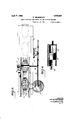
- Fig. l is a broken side elevation of the forwardend of a can clinching machine showing my improved sauce injecting device attached thereon.
- Fig. 2 is a broken transverse-vertical section of the machine showing the relation in which the pump and dispensingreceiver are mounted thereon.
- V Fig. 3 is a broken plan view of the machine as shown in Fig.1.
- Fig. 4 is a sectional detail of the pump connecting rod bearing mounting.
- Fig. 5 is a sectionaldetail of the dispens-1 7 ing receiver and plunger and the actuating means therefor.
- Fig. 6 is a sectional detail of the pump.
- the numeral 1 is used to designate in general the frame of a canclinching machine of the character in common use for applying and clinching the covers upon. cans 2.
- Machines of this character are'ofwell known construction and operation and no particular description is herein necessary other than that such machines 3 provided tensions l arranged to engage the cans 2 and move .the same intermittentlythrough the machine, said carrier bars heingrecipro catedby means of'a rocker-arm 6.actuatedby acam 7 and at the same time alternatelyv raised and lowered by means of a member 8 connected between the cam 7 and the carrier bars whereby the bars are raised to bring the extensions 4: into engagement with the cans during the forward movement of the carrier arms to carry the arms forward and to lower the carrier bar during the return movement thereof thereby permitting the extensions 4: to be moved rearwardly into engagement with the next succeeding can a number of cans being intermittently moved through successive steps in the can closing operation.
- My attachment consists of a pump designated by the numeral 11, secured upon a bracket 12 adjacent the forward end of the frame.
- the pump is provided with a plunger 13 and a connecting rod 14- pivotally connected between said plunger and a crank arm 16 secured upon the end of the main shaft 17 of the machine immediately in front of the cam 7
- the connecting rod is provided with a bearing portion 18 engaging a bearing pin 19 slidably mounted at its inner end within a slot 21 formed in the face of the crank arm 16.
- the bearing portion 18 is held in engagement with the pin 19 by means of a collar 20 secured by a screw 22 threaded into said pin and extending axially therethrough into engagement with the back of the T slot 21 whereby a tightening of the screw 22 will clamp the bearing pin in a desired position along the crank for a purpose hereinafter more fully explained.
- a supply tank 23 is mounted in any convenient manner adjacent the forward end of the machine 1, said tank being adapted to receive a supply of the sauce or dressing of any desired character.
- the tank 23 is connected with the pump 11 through a connection 24: whereby sauce may be drawn from the tank into the pump above the plunger during the suction stroke of the pump.
- a check valve 26 of any suitable construction is mounted within the connection 24 to prevent the return of the sauce to the supply tank during the succeeding pressure stroke of the pump.
- a dispensing receiver designated in general by the numeral 27 is mounted above the frame 1 of the machine immediately over a point momentarily occupied by successive cans 2 just before said cans are moved under the cover applying mechanism of the ma chine.
- the receiver 27 is connected to the pump 11 through a conduit connection 28 whereby sauce may be forced from the pump to said receiver, said connection 28 being provided with a suitable check valve 30 to prevent the return of sauce to the pump during the suction stroke thereof.
- a plunger 29 is slidably mounted within the receiver 27 said plunger being normally seated against a beveled shoulder 31 so positioned that the body of the plunger will normally close a dispensing opening 32 chine adjacent the receiver.
- the plunger is provided with a stem 33 extending outwardly from the receiver and connected to an upwardly extending arm 3 1 formed upon an actuating'member 36 pivotally mounted upon the frame 1 of the ma-
- a spring 37 is connected between the end of the arm 34: and the receiver to hold the actuating member 36 and theplunger 29 innormal position.
- a laterally disposed extension 35 is formed upon the inner side of the member 36 in a position to be engagedby the adjacent edges of cans moved under the dispensing receiver 27 whereby the actuating member is swung outwardly to move the plunger to dispensing position as shown in dotted lines in Fig. 4: of the drawings.
- a conduit connection 38 is connected between the conduit 28 and the supply tank 23, said connection being provided with a suitable valve 39 operating to normally close said connection 38 and being adapted to be opened by pressure to permit the return of sauce to the supply tank should the dispensing receiver remain closed during a pressure stroke of the pump 11 as hereinafter more fully explained.
- the present invention is primarily intended for use in the canning of sardines.
- the cans 2 which are of the ordinary oval shape, are initially filled with sardines in the ordinary manner. After the cans are filled they are moved by a suitable conveyor into position to be engaged by the carrier arms 3 of the machine whereby the cans are moved intermittently through the machine to be subjected to successive stops in the securing of the covers thereon.
- the carriers are driven from the main shaft of the machine as above described a full forward and return movement being made for each revolution of the shaft.
- the pump plunger is also driven from the main shaft and caused to make a full pressure and suction stroke during each revolution of the shaft,
- the movement of the pump plunger being timed to cause the pressure stroke to occur during the time the cans remain stationary and the suction stroke to occur during the time the cans are being moved forward to their next positions.
- the edge of the can en gages the actuating member and moves it outwardly thereby causing the plunger 29 to be moved to uncover the opening 32.
- the pump 11 makes its pressure stroke the sauce drawn from the supply tank during the preceding suction stroke will be forced through the conduit 28 into the receiver and thence through the opening 82 into the can.
- An attachment for can clinching ma-v chines of the character described comprising a pump having a plunger actuated in timed relation to the movement of cans moved intermittently through said machine; a supply tank connected to the pump for supplying sauce to the pump to be injected into the cans; a dispensing receiver.
- An attachment for can clinching machines of the character'described comprising a pump having a plunger actuated n timed relation to the movement of cans moved intermittently through said machine; a supply tank connected to the pump for supplying sauce to the pump to be injected into the cans; a despensing receiver mounted upon the machine above a POllltOCCHPlQd by successive cans just prior to reaching the cover applying mechanism of the machine and connected to the pump to receive sauce from the pump, said receiver having a dispensing opening; a plunger slidably mounted within the receiver and normally closing the dispensing opening in said receiver; and
- an actuating member pivotally mounted up on the machine adjacent the receiver and connected to the plunger therein said memher being provided with a lateral extension adapted to be engaged and moved by a can when moved under the receiver whereby the plunger is moved to uncover the dispensing opening whilethe can is thereunder and during the pressure stroke of the pump thereby and a by-pass adapted to deliver sauce back to the supply tank when the dispensing opening of the receiver remains closed due to the absence of a can thereunder during said pressure stroke.
- An attachment for can closing machines of the character described comprising a pump having a reciprocating plunger actuated in timed relation to the movement of cans moved intermittently through a can closing machine; .asupply tank having-a connection to the pump for supplying sauce to the pump to be injected'into the cans, said connection being provided with a check.
- valve adapted to prevent the return of sauce said conduit and receiver during the suction stroke of the pump plunger; a plunger slidably mounted within the dispensing receiver and normally closing the dispensing opening therein; a stem secured to the plunger and extending outwardly from the receiver; and an actuating member pivotally mounted up on the machine adjacent the receiver and connected to the plunger stem said member having a lateral extension adapted to be engaged and moved by the cans when moved under the dispensing receiver whereby the plunger is moved to uncover the dispensing opening in the receiver to permit sauce to be forced by the pump into the cans.
- An attachment for can closing machines of the character described comprising a pump having reciprocating plunger actuated in timed relation the movement of cans moved intermittently through a can closing machine; a supply tank having a connection to the pump for supplying sauce to the pump to be injected into the cans, said connection being provided with a check valve adapted to prevent the return of sauce therethrough to the supply tank during the pressure stroke of the phu 561; a dispensing receiver mounted upon the machine and having a dispensing opening above a point occupied by success eve cans just prior to reaching the cover applying mechanism; a conduit connected.
- said conduit being provided with a check valve adapted to prevent the return of sauce from said conduit and receiver during the suction stroke of the pump plunger; a plunger slidably mounted within the dispensing receiver and normally closing the dispensing opening therein; a stem secured to the plunger and extending outwardl' from the receiver; and an actuating member pivotally mounted upon the machine adjacent the receiver and connected to the plunger stem, said member having a lateral extension adapted to be engaged and moved by the cans when moved under the dispensing receiver whereby the plunger is moved to uncover the dispensing opening in the receiver to permit sauce to be forced by the pump into the cans; and a bypass adapted to deliver sauce back to the supply tank when the dispensing opening of the receiver remains closed due to the abseiice ota can thereunder during the pressure stroke of the pump.
- An attachment for can closing machines ot comprising a pump having a reciprocating plunger actuated in timed relation to the movement 01 cans moved intermittently through a canclosing machine; a supply tank having a connection to the pump for supplying sauce to the pump to be injected into the cans, said connection being provided with a check valve adapted to prevent the return of sauce therethrough to the supply tank during the pressure stroke of the plunger; a dispensing receiver mounted upon the machine and having a dispensing opening above a point occupied by successive cans just prior to reaching the cover applying mechanism; a conduit connected between the pump and the receiver to deliver sauce into said receiver, said conduit being provided with a check valve adapted to prevent the return of sauce from said conduit and receiver during the suction stroke of the pump plunger; a piunger slidably mounted within the dispensing receiver and normally closing the dispensing opening therein; a stem secured to the plunger and extending outwardly from the receiver; and an actuating member pivotally mounted upon the machine adj
Landscapes
- Engineering & Computer Science (AREA)
- Mechanical Engineering (AREA)
- Devices For Dispensing Beverages (AREA)
Description
A ril 6 1926. 1,579,434
w. BRQMBAKER SAUCE INJECTING ATTACHMENT FOR CAN CLOSING MACHINES Filed Dec. 15, 1924. 5 Sheets-5heet 1 Q I all WILLIAM BROHB R era 4 April 6 -,19zs.-
w-. 'BROMBAKER "swan INJECTING ATTACHMENT FOR CAN cL osmwmqnmEs Filed Dec; 15; 1934 sneets sneet 2 vVA/r0/P WILLIAM BROMBAKHZ April 6 1926.
w. BROMBA KER SAUCE INJECTING ATTACHMENT FQR CAN ,CLOSING IACHINBS Filed Dec. 15, 1924 "mllllllllllllmllillllh -3 Sheets-Sheet 3 T0 (ZZZ 107mm it may comer-11 Fatented Apr. 6, 1926 "UNITED STATES P'ATEN'TPOFFICEQ wILLIAMIBnoivrBA ER; or onrnnnz, CALIFORNIA.
'snncn-mmcrme" TTACH ENT FQR 'can-cnosnsro macr-rmns.
Appiicat-ionfiled Dec embcr l5, 1924. 7 Serial No. 755,991.
Be it known that I, VVILLI'AM BnoMisiiKnR, a citizen of the Jnrted States, residing in the city of Monterey, in the county -of'Mon-* terey and StateofiCalifornia,have invented a new and useful-Improvementin a Sauce- Injecting Attachment for Can-Closing Machines, of which the following is a specifica-' tion.
My invention relates to improvements in attachments for can clinching machines whereby sauceor dressing of a desired char .acter may be injected without waste into cans after said cans have been filled with the product being canned and just prior to the placing of the cover thereon.
The present invention is directed particularly to an improved device for injecting sauce or dressing into cans previously filled with sardines, the device being attached directly upon the canclinching machine and attached directly from the main driveshaft of said machine to automatically inject a predetermined quantity of sauce into the can. I
In the present practice of canning sar the can is not accurately regulatedand to the further fact that, of thequantity of sauce initially placed in the can, a consider able portion is displaced from the can when the sardines'are being packed therein, the displaced-quantities of sauce being entirely wasted and causing an undesirable muss about the packingtable.
My invention is therefore directed to an improved sauce injecting means adapted to overcome these objectional features of the present practice, the primary objectof the inventionbeing to provide an improved device which will facilitate the introduction of the sauce or dressing into the cans with.
out causing muss and without wasting said sauce'or dressing. j
Another object of my invention is to provide a device which is attached directly in are provided with carrier bars with a pluralitygof"upwardlydisposed exconnection with the can clinching machine and actuated in common. therewith to intro-. 7
duce the sauce or dressing intoathe cans after filling and ust prior to the closing or clinchmg. of the cans.
A further object is to. provide a device which will dispense a-pred-etermined quantity of sauce into each can or which will automatically return the chargeof sauce *to the source of supply when no can is in position'to receive the charge.
,A. still further object'is to provide a device which maybe readily attached upon the standard-can closing or clinching machine at a nominal cost and without material all teration thereof and without impairing or interfering in'any manner withthe operat on of the machine. r
I accomplish these and other-objects-by means of the device disclosed in the drawin-gs forming a part of the present specification wherein like characters of reference are used to designate similar parts throughout saidspecitication and drawings and-in which, 1
Fig. l is a broken side elevation of the forwardend of a can clinching machine showing my improved sauce injecting device attached thereon.
Fig. 2 is a broken transverse-vertical section of the machine showing the relation in which the pump and dispensingreceiver are mounted thereon. V Fig. 3 is a broken plan view of the machine as shown in Fig.1.
Fig. 4 is a sectional detail of the pump connecting rod bearing mounting.
Fig. 5 is a sectionaldetail of the dispens-1 7 ing receiver and plunger and the actuating means therefor. p
Fig. 6 is a sectional detail of the pump. Referring to the drawings the numeral 1 is used to designate in general the frame of a canclinching machine of the character in common use for applying and clinching the covers upon. cans 2. Machines of this character are'ofwell known construction and operation and no particular description is herein necessary other than that such machines 3 provided tensions l arranged to engage the cans 2 and move .the same intermittentlythrough the machine, said carrier bars heingrecipro catedby means of'a rocker-arm 6.actuatedby acam 7 and at the same time alternatelyv raised and lowered by means of a member 8 connected between the cam 7 and the carrier bars whereby the bars are raised to bring the extensions 4: into engagement with the cans during the forward movement of the carrier arms to carry the arms forward and to lower the carrier bar during the return movement thereof thereby permitting the extensions 4: to be moved rearwardly into engagement with the next succeeding can a number of cans being intermittently moved through successive steps in the can closing operation.
My attachment consists of a pump designated by the numeral 11, secured upon a bracket 12 adjacent the forward end of the frame. The pump is provided with a plunger 13 and a connecting rod 14- pivotally connected between said plunger and a crank arm 16 secured upon the end of the main shaft 17 of the machine immediately in front of the cam 7 The connecting rod is provided with a bearing portion 18 engaging a bearing pin 19 slidably mounted at its inner end within a slot 21 formed in the face of the crank arm 16. The bearing portion 18 is held in engagement with the pin 19 by means of a collar 20 secured by a screw 22 threaded into said pin and extending axially therethrough into engagement with the back of the T slot 21 whereby a tightening of the screw 22 will clamp the bearing pin in a desired position along the crank for a purpose hereinafter more fully explained.
A supply tank 23 is mounted in any convenient manner adjacent the forward end of the machine 1, said tank being adapted to receive a supply of the sauce or dressing of any desired character. The tank 23 is connected with the pump 11 through a connection 24: whereby sauce may be drawn from the tank into the pump above the plunger during the suction stroke of the pump. A check valve 26 of any suitable construction is mounted within the connection 24 to prevent the return of the sauce to the supply tank during the succeeding pressure stroke of the pump.
A dispensing receiver designated in general by the numeral 27 is mounted above the frame 1 of the machine immediately over a point momentarily occupied by successive cans 2 just before said cans are moved under the cover applying mechanism of the ma chine. The receiver 27 is connected to the pump 11 through a conduit connection 28 whereby sauce may be forced from the pump to said receiver, said connection 28 being provided with a suitable check valve 30 to prevent the return of sauce to the pump during the suction stroke thereof.
A plunger 29 is slidably mounted within the receiver 27 said plunger being normally seated against a beveled shoulder 31 so positioned that the body of the plunger will normally close a dispensing opening 32 chine adjacent the receiver.
formed in the lower side of the receiver. The plunger is provided with a stem 33 extending outwardly from the receiver and connected to an upwardly extending arm 3 1 formed upon an actuating'member 36 pivotally mounted upon the frame 1 of the ma- A spring 37 is connected between the end of the arm 34: and the receiver to hold the actuating member 36 and theplunger 29 innormal position. A laterally disposed extension 35 is formed upon the inner side of the member 36 in a position to be engagedby the adjacent edges of cans moved under the dispensing receiver 27 whereby the actuating member is swung outwardly to move the plunger to dispensing position as shown in dotted lines in Fig. 4: of the drawings.
A conduit connection 38 is connected between the conduit 28 and the supply tank 23, said connection being provided with a suitable valve 39 operating to normally close said connection 38 and being adapted to be opened by pressure to permit the return of sauce to the supply tank should the dispensing receiver remain closed during a pressure stroke of the pump 11 as hereinafter more fully explained.
As above mentioned, the present invention is primarily intended for use in the canning of sardines. In this connection the operation is as follows. The cans 2, which are of the ordinary oval shape, are initially filled with sardines in the ordinary manner. After the cans are filled they are moved by a suitable conveyor into position to be engaged by the carrier arms 3 of the machine whereby the cans are moved intermittently through the machine to be subjected to successive stops in the securing of the covers thereon. The carriers are driven from the main shaft of the machine as above described a full forward and return movement being made for each revolution of the shaft. The pump plunger is also driven from the main shaft and caused to make a full pressure and suction stroke during each revolution of the shaft,
the movement of the pump plunger being timed to cause the pressure stroke to occur during the time the cans remain stationary and the suction stroke to occur during the time the cans are being moved forward to their next positions.
As the cans are moved under the dispensing receiver the edge of the can en gages the actuating member and moves it outwardly thereby causing the plunger 29 to be moved to uncover the opening 32. When now the pump 11 makes its pressure stroke the sauce drawn from the supply tank during the preceding suction stroke will be forced through the conduit 28 into the receiver and thence through the opening 82 into the can.
a is.
If for any reason a can 2 fails to be moved into position under the dispensing receiver, the plunger 29 will be held seated against shoulder 31 thereby preventing sauce fron'ibeing dispensed. vIn this event the pressure which will be caused in the connection 28 will overcome the normal resistance of the valve 39 .in: the connection 38 whereby the sauce supplied from the pump will be delivered back through-said connection 38 into the supply tank, in this manner avoiding all Waste of the sauce.
In order to regulate the quantity ofsauce dispensed into each can I have providedv means for adjusting the throw of the pump plunger 13. -This is accomplished by adjusting the position of the connecting rod bearing pin along the actuating crankarm 16 as above explained; By increasing the. 'distance from the center of the bearing pin to the center of the shaft 17 the total movement of the plunger willbe increased and a proportionally greater quantity of sauce will be drawn into the pump and dispensed through the dispensing receiver at-each operation, in this manner affording a convenient means of ad usting the quan tity of sauce dispensed to the cans.
sauce dispensed at each operation will of course be LllllfOIIIl.
While I have illustrated the preferred construction of my device as used in the canning of sardines, the device may of course be modified in numerous ways and adapted for use in canning of other products. I therefore do notwishto restrict myself to the specific form and construction of the device or its particular application as herein "described, but desire to avail myself of all modifications which may fall within the scope of the appended claims.
Having thus described my invention what I claim as new and desireto secure by Letters Patent-"is: f i r 1. An attachment for can clinching ma-v chines of the character described comprising a pump having a plunger actuated in timed relation to the movement of cans moved intermittently through said machine; a supply tank connected to the pump for supplying sauce to the pump to be injected into the cans; a dispensing receiver. mounted upon the machine above a point occupied by suc cessive cans just prior to reaching the cover applying mechanism of the machine and connected to the pump to receive sauce from the pump; said receiver having a dispensing opening; a plunger slidably mounted within the receiver and normally closingthe dispensing opening in said receiver; and an actuating member pivotally mounted upon the machine adjacent the receiver and connected to the plunger therein, said member being provided with a lateral extension For i 1 any particular adjustment the quantity of adapted to, be engaged and moved by a can when moved under the receiver whereby the plunger is moved to uncover the dispensing opening while the can is thereunder and during the pressure stroke/of the pump thereby permitting sauce to be forced into the can.
i 2. An attachment for can clinching machines: of the character'described comprising a pump having a plunger actuated n timed relation to the movement of cans moved intermittently through said machine; a supply tank connected to the pump for supplying sauce to the pump to be injected into the cans; a despensing receiver mounted upon the machine above a POllltOCCHPlQd by successive cans just prior to reaching the cover applying mechanism of the machine and connected to the pump to receive sauce from the pump, said receiver having a dispensing opening; a plunger slidably mounted within the receiver and normally closing the dispensing opening in said receiver; and
an actuating member pivotally mounted up on the machine adjacent the receiver and connected to the plunger therein said memher being provided with a lateral extension adapted to be engaged and moved by a can when moved under the receiver whereby the plunger is moved to uncover the dispensing opening whilethe can is thereunder and during the pressure stroke of the pump thereby and a by-pass adapted to deliver sauce back to the supply tank when the dispensing opening of the receiver remains closed due to the absence of a can thereunder during said pressure stroke. 1
"permitting sauce to be forced into the can;
3. An attachment for can closing machines of the character described comprising a pump having a reciprocating plunger actuated in timed relation to the movement of cans moved intermittently through a can closing machine; .asupply tank having-a connection to the pump for supplying sauce to the pump to be injected'into the cans, said connection being provided with a check. valve adapted to prevent the return of sauce said conduit and receiver during the suction stroke of the pump plunger; a plunger slidably mounted within the dispensing receiver and normally closing the dispensing opening therein; a stem secured to the plunger and extending outwardly from the receiver; and an actuating member pivotally mounted up on the machine adjacent the receiver and connected to the plunger stem said member having a lateral extension adapted to be engaged and moved by the cans when moved under the dispensing receiver whereby the plunger is moved to uncover the dispensing opening in the receiver to permit sauce to be forced by the pump into the cans.
4:. An attachment for can closing machines of the character described comprising a pump having reciprocating plunger actuated in timed relation the movement of cans moved intermittently through a can closing machine; a supply tank having a connection to the pump for supplying sauce to the pump to be injected into the cans, said connection being provided with a check valve adapted to prevent the return of sauce therethrough to the supply tank during the pressure stroke of the phu 561; a dispensing receiver mounted upon the machine and having a dispensing opening above a point occupied by success eve cans just prior to reaching the cover applying mechanism; a conduit connected. between the pump and the receiver to deliver sauce into said receiver said conduit being provided with a check valve adapted to prevent the return of sauce from said conduit and receiver during the suction stroke of the pump plunger; a plunger slidably mounted within the dispensing receiver and normally closing the dispensing opening therein; a stem secured to the plunger and extending outwardl' from the receiver; and an actuating member pivotally mounted upon the machine adjacent the receiver and connected to the plunger stem, said member having a lateral extension adapted to be engaged and moved by the cans when moved under the dispensing receiver whereby the plunger is moved to uncover the dispensing opening in the receiver to permit sauce to be forced by the pump into the cans; and a bypass adapted to deliver sauce back to the supply tank when the dispensing opening of the receiver remains closed due to the abseiice ota can thereunder during the pressure stroke of the pump.
An attachment for can closing machines ot." the character described comprising a pump having a reciprocating plunger actuated in timed relation to the movement 01 cans moved intermittently through a canclosing machine; a supply tank having a connection to the pump for supplying sauce to the pump to be injected into the cans, said connection being provided with a check valve adapted to prevent the return of sauce therethrough to the supply tank during the pressure stroke of the plunger; a dispensing receiver mounted upon the machine and having a dispensing opening above a point occupied by successive cans just prior to reaching the cover applying mechanism; a conduit connected between the pump and the receiver to deliver sauce into said receiver, said conduit being provided with a check valve adapted to prevent the return of sauce from said conduit and receiver during the suction stroke of the pump plunger; a piunger slidably mounted within the dispensing receiver and normally closing the dispensing opening therein; a stem secured to the plunger and extending outwardly from the receiver; and an actuating member pivotally mounted upon the machine adj acent the receiver and connected to the phmger stem, said member having a lateral extension adapted to be engaged and moved by the cans when moved under the dispensing receiver whereby the plunger is moved to uncover the dispensing opening in the receiver to permit sauce to be forced by the pump into the cans; and means for varying the stroke of the pump plunger to regulate the quantity of sauce dispensed into each can.
In witness whereof I hereunto set my signature.
WILLIAM BROMBAKER.
Priority Applications (1)
| Application Number | Priority Date | Filing Date | Title |
|---|---|---|---|
| US755991A US1579434A (en) | 1924-12-15 | 1924-12-15 | Sauce-injecting attachment for can-closing machines |
Applications Claiming Priority (1)
| Application Number | Priority Date | Filing Date | Title |
|---|---|---|---|
| US755991A US1579434A (en) | 1924-12-15 | 1924-12-15 | Sauce-injecting attachment for can-closing machines |
Publications (1)
| Publication Number | Publication Date |
|---|---|
| US1579434A true US1579434A (en) | 1926-04-06 |
Family
ID=25041553
Family Applications (1)
| Application Number | Title | Priority Date | Filing Date |
|---|---|---|---|
| US755991A Expired - Lifetime US1579434A (en) | 1924-12-15 | 1924-12-15 | Sauce-injecting attachment for can-closing machines |
Country Status (1)
| Country | Link |
|---|---|
| US (1) | US1579434A (en) |
Cited By (3)
| Publication number | Priority date | Publication date | Assignee | Title |
|---|---|---|---|---|
| US2757845A (en) * | 1952-02-02 | 1956-08-07 | Alfred F Luthi | Apparatus for filling receptacles |
| US2877929A (en) * | 1956-06-06 | 1959-03-17 | Indiana Steel Products Co | Slurry feeder |
| US3195781A (en) * | 1962-10-22 | 1965-07-20 | Ex Cell O Corp | Liquid filling apparatus |
-
1924
- 1924-12-15 US US755991A patent/US1579434A/en not_active Expired - Lifetime
Cited By (3)
| Publication number | Priority date | Publication date | Assignee | Title |
|---|---|---|---|---|
| US2757845A (en) * | 1952-02-02 | 1956-08-07 | Alfred F Luthi | Apparatus for filling receptacles |
| US2877929A (en) * | 1956-06-06 | 1959-03-17 | Indiana Steel Products Co | Slurry feeder |
| US3195781A (en) * | 1962-10-22 | 1965-07-20 | Ex Cell O Corp | Liquid filling apparatus |
Similar Documents
| Publication | Publication Date | Title |
|---|---|---|
| US2103302A (en) | Band applying machine | |
| US2089769A (en) | Band forming and applying machine | |
| US1579434A (en) | Sauce-injecting attachment for can-closing machines | |
| US2654343A (en) | Machine for manufacturing container elements and the like | |
| US1951340A (en) | Fuel pump for internal combustion engines | |
| US2107274A (en) | Filling machine | |
| US2227378A (en) | Packaging machine and method of packaging | |
| US3848396A (en) | Means for depositing lids on filled containers and then seating said lids in sealing condition on such containers | |
| US1907900A (en) | Conveying mechanism | |
| US2789589A (en) | Bypass system for filling machines | |
| US3428000A (en) | Pastry filling machine | |
| US2026856A (en) | Timing and safety device for bottle conveyers | |
| US1919155A (en) | Can positioning mechanism for liquid dispensing | |
| US2888046A (en) | Receptacle filling mechanism | |
| US2176448A (en) | Can filling machine | |
| US2300704A (en) | Machine for cleaning packed cans | |
| US1820480A (en) | Brine supplying attachment for can closing machines | |
| US1307898A (en) | Bottle fh | |
| US1697611A (en) | Hydraulic cushion for sheet-metal presses | |
| US2202269A (en) | Overfeed device | |
| US1366742A (en) | Can-capping machine | |
| US2037691A (en) | Multiple filling machine | |
| US2077647A (en) | Filling and closing machine | |
| US938460A (en) | Machine for applying cement to can-caps. | |
| US2080482A (en) | Container filling machine |