US1576537A - Air register for fuel burners - Google Patents
Air register for fuel burners Download PDFInfo
- Publication number
- US1576537A US1576537A US633169A US63316923A US1576537A US 1576537 A US1576537 A US 1576537A US 633169 A US633169 A US 633169A US 63316923 A US63316923 A US 63316923A US 1576537 A US1576537 A US 1576537A
- Authority
- US
- United States
- Prior art keywords
- air
- conical
- cylindrical
- frusto
- register
- Prior art date
- Legal status (The legal status is an assumption and is not a legal conclusion. Google has not performed a legal analysis and makes no representation as to the accuracy of the status listed.)
- Expired - Lifetime
Links
Images

Classifications
-
- F—MECHANICAL ENGINEERING; LIGHTING; HEATING; WEAPONS; BLASTING
- F23—COMBUSTION APPARATUS; COMBUSTION PROCESSES
- F23C—METHODS OR APPARATUS FOR COMBUSTION USING FLUID FUEL OR SOLID FUEL SUSPENDED IN A CARRIER GAS OR AIR
- F23C7/00—Combustion apparatus characterised by arrangements for air supply
- F23C7/008—Flow control devices
Definitions
- This invention relates to a system-0r air control registers for fuel burners, preferably of the mechanical a-tomizing type which finely atomizes the fuel entirely by pressure and produces a hollow conical spray, and
- Figure 1 is a central vertical sectional view of my register mounted in a furnace front.
- Figure 2 is a view, partly broken away, of the front plate.
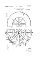
- Figure 3 is a view of my register partly broken away with the front plate removed.
- the refractory wall 1 of any suitable furnace is provided with a circular opening 2 into which a conical annular ring 3 is secured by any convenient means such as bolts 4 tothe front plate 5.
- Coaxial with the conical member3 I provide a cylindrical member 8 having a reduced portion or sleeve 9 adapted to hold the burner 10 provided with tip 11, fuel supply 12 and diffuser plate 13.
- burner is adapted to slide withinythe sleeve and be held in adjusted position by means of the thumb screw 14.
- Spirally arranged deflector plates 16 hold the conical member 3 and the cylindrical member 8 in spaced relation and the latter is provided with openings 15 which are located between the deflector plates 16 and form a plurality of air ducts which converge from the outer to inner portion having a section of maximum restriction near the combustion chamber substantially like the converging nozzle used in elastic fluid turbines of the impulse type for converting pressure into velocity.
- a front plate 20 adapted to slide and rotate to control the air passing into andthrough the air passages in the register.
- I provide a plurality of openings 21 in the flat face 19 of the cylindrical portion 8 and in front of these openings I provide a shutter 26 operated by handle 22 suitably guided as at 23 and secured in its adjusted I position by thumb screw 24.
- This shutter 26 is provided with openings 27 similarly arranged with holes 21 in plate 19.
- An air control re ister comprisin an atomizer adapted to deliver fuel in the s ape of a conical spray into a'combnstion chamber, a frusto-conical ring-like member adapted to fit into an opening in the front of the combustion chambena cyhn'drical memof a conical spra ber coaxial with the frusto-conical member, a plurality of spirally arranged deflector plates interposed between and connecting the conical member and the cylindrical member and adapted to direct the air into the combustion chamber, and rotatable and slidable means for the control of the air through the passages between the two members.
- An air control register comprising an atomizer adapted to deliver fuel in the shape into a combustion chamber, a frusto-comcal member adapted to fit into an opening in the combustion chamber, a cylindrical member in spaced relation thereto and spaced from the atomizer and a plurality of spirally arranged deflector plates interposed between and connecting the frusto-conical and cylindrical members adapted to direct the air to the combustion chamber so that it impinges upon the cone of fuel.
- a device as recited in claim 2 with the addition of means for controlling the amount of air entering between the frusto-conical and cylindrical members.
- An air control register comprising a frusto-conical member adapted to-fit into an opening in the furnace front, a member provided with a cylindrical body portion and a reduced cylindrical sleeve adapted to receive an atomizer, a plurality of spirally arranged deflector plates interposed between the frusto-conical member and the cylindrical body portion, and rotatable and slidable means for control of the passage of air through the openings between the deflector plates.
- An air control register comprisin an outer frusto-conical ring-like member a apted to'be secured to a furnace front, an inner cylindrical portion for the admission of air, and a series of spirally arranged partitions securing the inner portion to the outer member in spaced relation.
- An air register comprising an outer frusto-conical ring-like member adapted to be secured to a furnace front, an inner cylindrical member provided with a reduced portion, a series of spirally arranged partitions securing the inner member to the outer member, and a rotatable and slidable member mounted on the reduced portion of the cylindrical member for controlling the admission of air.
- An air control register comprising an atomizer adapted to deliver fuel in the shape of a conical spray into a combustion chamber, a frusto-conical ring-like member adapted to fit into an opening in thefront of the combustion chamber, a cylindrical member coaxial with the frusto-conical member and spaced from the atomizer, a plurality of spirally arranged deflector plates interposed between and connecting the frustoconical member and the cylindrical member and adapted to direct the air into the combustion chamber, and means for the control of the air through the passages between said members.
- An air control register comprising a frusto-conical member adapted to fit into an opening in the furnace front, a member provided with a cylindrical body portion and a reduced cylindrical sleeve adapted to receive an atomizer, a plurality of spirally arranged deflector plates interposed between the frusto-conical member and the cylindrical body portion, and means for control of the passage of air through the openings between the deflector plates.
- An air register comprising an outer frusto-conical ring-like member adapted to be secured to a furnace front, an inner cylindrical member provided with a reduced portion, a series of spirally arranged partitions securing the inner member to the outer member, and a member mounted on the reduced portion of the cylindrical memher for. controlling the admission of air.
- An air control register comprising an outer frusto-conical ring-like member adapted to be secured to a furnace front, an inner cylindrical portion having its outer face closed except for air openings, fuel supply means within said cylindrical portion, spirally arranged partitions connecting the member and the inner portion, and means for cont-rolling the passage of air through said openings.
- An air control register comprising an outer frusto-conical ring-like member adapted to be secured to a furnace front, an inner cylindrical member having a closed outer end provided with openings and a reduced cylindrical sleeve to receive! an atomizer,
Landscapes
- Engineering & Computer Science (AREA)
- Chemical & Material Sciences (AREA)
- Combustion & Propulsion (AREA)
- Mechanical Engineering (AREA)
- General Engineering & Computer Science (AREA)
- Nozzles For Spraying Of Liquid Fuel (AREA)
Description
E. H. PEABODY AIR REGISTER FOR FUEL BURNERS March 16 1926. 1,576,537
Filed April 19, 1923 2 Sheets-Sheet 1 INVENTOR' Ernest H. Peabody Um. 36am- ATTORNEY March 16 1926. 1,576,537
E. H. PEABODY AIR REGISTER FOR FUEL BURNERS Filed April 19. 1923 2 Sheets-Sheet E f INVENTOR Ernest H. Peabody wmdlfimbh ATTORNEY Patented Mar. 16', 1926.
UNITED STATES ERNEST H. PEABODY, OF PELHAM MANOR, NEW YORK.
AIR nnefs'rna' FOR FUEL Bonuses.
Application filed April 19, 1923. Serial No. 633,169.
To all whom it may concern:
Be it known that I, ERNEST H. PEAnonY, a citizen of the United States, and resident of Pelham Manor, county of Westchester, State of New York, have invented certain new and useful Improvements in Air Registers for Fuel Burners; and I do hereby declare the following to be a full, clear, and exact deseription of the invention, such as will enable others skilled in the art towhich it appertains to make and use the same.
This invention relates to a system-0r air control registers for fuel burners, preferably of the mechanical a-tomizing type which finely atomizes the fuel entirely by pressure and produces a hollow conical spray, and
has for its objects to produce a register that will delii'er the required air supply uniformly and in a direction converging to the flame so that each particle of fuel will be supplied with its required amount of oxygen for complete combustion within the cone of fuel as well as on the outside surface.
It is Well known that efficient combustion can be produced only by atomization of the oil into its finest particles. If each particle is 'far enough apart from its neighbor to permit being completely surrounded with invention will now be described in connection with the accompanying drawings, forming part of this specification, in which I have represented my air register in ts pre ferred form, after, which I shall point out more particularly in the claims those features which I believe to be new and of my own invention. y
In the drawings Figure 1 is a central vertical sectional view of my register mounted in a furnace front.
Figure 2 is a view, partly broken away, of the front plate.
Figure 3 is a view of my register partly broken away with the front plate removed.
In the carrying out of my invention, the refractory wall 1 of any suitable furnace is provided with a circular opening 2 into which a conical annular ring 3 is secured by any convenient means such as bolts 4 tothe front plate 5. The inner end of the conical ri-n ang e with the refractory wall 1 of the furnace, which is filled in with plastic refractory material 7.
3 is flanged as at 6 forming a right.
Coaxial with the conical member3 I provide a cylindrical member 8 having a reduced portion or sleeve 9 adapted to hold the burner 10 provided with tip 11, fuel supply 12 and diffuser plate 13. The
burner is adapted to slide withinythe sleeve and be held in adjusted position by means of the thumb screw 14. Spirally arranged deflector plates 16 hold the conical member 3 and the cylindrical member 8 in spaced relation and the latter is provided with openings 15 which are located between the deflector plates 16 and form a plurality of air ducts which converge from the outer to inner portion having a section of maximum restriction near the combustion chamber substantially like the converging nozzle used in elastic fluid turbines of the impulse type for converting pressure into velocity.
Mounted on the sleeve 9 I provide a front plate 20 adapted to slide and rotate to control the air passing into andthrough the air passages in the register.
I provide a plurality of openings 21 in the flat face 19 of the cylindrical portion 8 and in front of these openings I provide a shutter 26 operated by handle 22 suitably guided as at 23 and secured in its adjusted I position by thumb screw 24. ,This shutter 26 is provided with openings 27 similarly arranged with holes 21 in plate 19.
From the foregoing description it will be apparent that the air passages between the conical member 3 and the cylindrical member 8 separated from each other by the spiral partitions 16 converge toward the combustion chamber. Each passage gradually changes in section to maximum restriction at the combustion chamber end.
The air'of combustion in flowing through 1 a passage so proportioned will expand adiabatically to the lesser pressure existing at the throat and issue uniformly as a continuous stream possessed of a definite velocity in a direction convergent to the flame so that it will enetrate' the conical layer of ignited fuel owing from the burner and enter the furnace as a highly incandescent gaseous mixture. K
1. An air control re ister comprisin an atomizer adapted to deliver fuel in the s ape of a conical spray into a'combnstion chamber, a frusto-conical ring-like member adapted to fit into an opening in the front of the combustion chambena cyhn'drical memof a conical spra ber coaxial with the frusto-conical member, a plurality of spirally arranged deflector plates interposed between and connecting the conical member and the cylindrical member and adapted to direct the air into the combustion chamber, and rotatable and slidable means for the control of the air through the passages between the two members.
2. An air control register comprising an atomizer adapted to deliver fuel in the shape into a combustion chamber, a frusto-comcal member adapted to fit into an opening in the combustion chamber, a cylindrical member in spaced relation thereto and spaced from the atomizer and a plurality of spirally arranged deflector plates interposed between and connecting the frusto-conical and cylindrical members adapted to direct the air to the combustion chamber so that it impinges upon the cone of fuel.
3. A device as recited in claim 2 with the addition of means for controlling the amount of air entering between the frusto-conical and cylindrical members. I
4. An air control register comprising a frusto-conical member adapted to-fit into an opening in the furnace front, a member provided with a cylindrical body portion and a reduced cylindrical sleeve adapted to receive an atomizer, a plurality of spirally arranged deflector plates interposed between the frusto-conical member and the cylindrical body portion, and rotatable and slidable means for control of the passage of air through the openings between the deflector plates.
5. An air control register comprisin an outer frusto-conical ring-like member a apted to'be secured to a furnace front, an inner cylindrical portion for the admission of air, and a series of spirally arranged partitions securing the inner portion to the outer member in spaced relation.
6. An air register comprising an outer frusto-conical ring-like member adapted to be secured to a furnace front, an inner cylindrical member provided with a reduced portion, a series of spirally arranged partitions securing the inner member to the outer member, and a rotatable and slidable member mounted on the reduced portion of the cylindrical member for controlling the admission of air.
7. An air control register comprising an atomizer adapted to deliver fuel in the shape of a conical spray into a combustion chamber, a frusto-conical ring-like member adapted to fit into an opening in thefront of the combustion chamber, a cylindrical member coaxial with the frusto-conical member and spaced from the atomizer, a plurality of spirally arranged deflector plates interposed between and connecting the frustoconical member and the cylindrical member and adapted to direct the air into the combustion chamber, and means for the control of the air through the passages between said members.
8. An air control register comprising a frusto-conical member adapted to fit into an opening in the furnace front, a member provided with a cylindrical body portion and a reduced cylindrical sleeve adapted to receive an atomizer, a plurality of spirally arranged deflector plates interposed between the frusto-conical member and the cylindrical body portion, and means for control of the passage of air through the openings between the deflector plates.
9. An air register comprising an outer frusto-conical ring-like member adapted to be secured to a furnace front, an inner cylindrical member provided with a reduced portion, a series of spirally arranged partitions securing the inner member to the outer member, and a member mounted on the reduced portion of the cylindrical memher for. controlling the admission of air.
.10. An air control register comprising an outer frusto-conical ring-like member adapted to be secured to a furnace front, an inner cylindrical portion having its outer face closed except for air openings, fuel supply means within said cylindrical portion, spirally arranged partitions connecting the member and the inner portion, and means for cont-rolling the passage of air through said openings. 11. A device as recited in claim 10 with the addition of means for controlling the passage of air between the member and the inner portion.
12. An air control register comprising an outer frusto-conical ring-like member adapted to be secured to a furnace front, an inner cylindrical member having a closed outer end provided with openings and a reduced cylindrical sleeve to receive! an atomizer,
means for connecting the two members,
means for controlling the passage of air through said openings, and means slidable on the sleeve for controlling the passage of air between the two members.
In testimony whereof I aflix my signature.
ERNEST PEABODY.
Priority Applications (1)
| Application Number | Priority Date | Filing Date | Title |
|---|---|---|---|
| US633169A US1576537A (en) | 1923-04-19 | 1923-04-19 | Air register for fuel burners |
Applications Claiming Priority (1)
| Application Number | Priority Date | Filing Date | Title |
|---|---|---|---|
| US633169A US1576537A (en) | 1923-04-19 | 1923-04-19 | Air register for fuel burners |
Publications (1)
| Publication Number | Publication Date |
|---|---|
| US1576537A true US1576537A (en) | 1926-03-16 |
Family
ID=24538553
Family Applications (1)
| Application Number | Title | Priority Date | Filing Date |
|---|---|---|---|
| US633169A Expired - Lifetime US1576537A (en) | 1923-04-19 | 1923-04-19 | Air register for fuel burners |
Country Status (1)
| Country | Link |
|---|---|
| US (1) | US1576537A (en) |
Cited By (6)
| Publication number | Priority date | Publication date | Assignee | Title |
|---|---|---|---|---|
| US2981320A (en) * | 1957-09-23 | 1961-04-25 | Zink Co John | Air register for fuel burner |
| US3168131A (en) * | 1961-06-06 | 1965-02-02 | Milton L Tolmach | Fuel burner nozzle |
| US3405923A (en) * | 1966-09-08 | 1968-10-15 | Midland Ross Corp | Side wall firing system for multi-stand annealing covers |
| US4155701A (en) * | 1977-09-26 | 1979-05-22 | The Trane Company | Variable capacity burner assembly |
| EP2256407A1 (en) * | 2009-05-27 | 2010-12-01 | IHI Corporation | Burner |
| US20130029274A1 (en) * | 2009-11-16 | 2013-01-31 | Safwan Yousif | Flow Control Device |
-
1923
- 1923-04-19 US US633169A patent/US1576537A/en not_active Expired - Lifetime
Cited By (10)
| Publication number | Priority date | Publication date | Assignee | Title |
|---|---|---|---|---|
| US2981320A (en) * | 1957-09-23 | 1961-04-25 | Zink Co John | Air register for fuel burner |
| US3168131A (en) * | 1961-06-06 | 1965-02-02 | Milton L Tolmach | Fuel burner nozzle |
| US3405923A (en) * | 1966-09-08 | 1968-10-15 | Midland Ross Corp | Side wall firing system for multi-stand annealing covers |
| US4155701A (en) * | 1977-09-26 | 1979-05-22 | The Trane Company | Variable capacity burner assembly |
| EP2256407A1 (en) * | 2009-05-27 | 2010-12-01 | IHI Corporation | Burner |
| US20110127355A1 (en) * | 2009-05-27 | 2011-06-02 | Ihi Corporation | Burner |
| US8646394B2 (en) | 2009-05-27 | 2014-02-11 | Ihi Corporation | Burner |
| US8820249B2 (en) | 2009-05-27 | 2014-09-02 | Ihi Corporation | Burner |
| US20130029274A1 (en) * | 2009-11-16 | 2013-01-31 | Safwan Yousif | Flow Control Device |
| US9328917B2 (en) * | 2009-11-16 | 2016-05-03 | Doosan Babcock Limited | Flow control device |
Similar Documents
| Publication | Publication Date | Title |
|---|---|---|
| US2933259A (en) | Nozzle head | |
| US3217779A (en) | Gas and liquid fuel burner combination | |
| US721900A (en) | Oil-burner. | |
| US2734560A (en) | Burner and combustion system | |
| US1576537A (en) | Air register for fuel burners | |
| GB1213788A (en) | Device for converting liquid fuel to micron size droplets | |
| US2285689A (en) | Atomizer | |
| US1587249A (en) | Method of and apparatus for burning oil | |
| US2242797A (en) | Method of and apparatus for burning fluid fuel | |
| US1593186A (en) | Atomizer for liquid fuel and the like | |
| US1893533A (en) | Gas burner | |
| US1321358A (en) | Burner | |
| US2660230A (en) | Oil burner | |
| US2931430A (en) | Combination oil and gas burner | |
| US1020612A (en) | Hydrocarbon-burner. | |
| US1865983A (en) | Fuel burning apparatus | |
| US1713259A (en) | Apparatus for atomizing and spraying | |
| US1698169A (en) | Air register for fuel burners | |
| US1400657A (en) | Combined oil and gas burner | |
| US777680A (en) | Oil-burner. | |
| US2514581A (en) | Method and atomizer for atomizing fuel oil | |
| US2238806A (en) | Oil burner | |
| US2530269A (en) | Atomizer for oil burners | |
| US2869632A (en) | Pressure gas burners | |
| US1596667A (en) | Gas burner |