US1562963A - Automatic planimeter - Google Patents
Automatic planimeter Download PDFInfo
- Publication number
- US1562963A US1562963A US712107A US71210724A US1562963A US 1562963 A US1562963 A US 1562963A US 712107 A US712107 A US 712107A US 71210724 A US71210724 A US 71210724A US 1562963 A US1562963 A US 1562963A
- Authority
- US
- United States
- Prior art keywords
- wheel
- disk
- integrator
- planimeter
- bridge
- Prior art date
- Legal status (The legal status is an assumption and is not a legal conclusion. Google has not performed a legal analysis and makes no representation as to the accuracy of the status listed.)
- Expired - Lifetime
Links
Images


Classifications
-
- G—PHYSICS
- G01—MEASURING; TESTING
- G01B—MEASURING LENGTH, THICKNESS OR SIMILAR LINEAR DIMENSIONS; MEASURING ANGLES; MEASURING AREAS; MEASURING IRREGULARITIES OF SURFACES OR CONTOURS
- G01B5/00—Measuring arrangements characterised by the use of mechanical techniques
- G01B5/26—Measuring arrangements characterised by the use of mechanical techniques for measuring areas, e.g. planimeters
Definitions
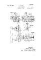
- HERM AUTOMATIC PLANIMETER F May @924 10 Sheets-Sheet e Nov. 24, 1925- 0.
- G HERM AUTOMATIC PLANIMETER Filed May 9, 1924 10 sheets-sheet v [jibe]; for
- the object of my invention is to provide a planimeter of simple, durable and inexpensive construction which is accurate in its measurements and which is easy to operate, and particularly adapted to be used in connection with survey work.
- a further object is to provide an improved planimeter for the purpose of measuring the area of regular and irregular polygons or cross sections without first having to'plat the polygon and then trace the same by a planimeter such as is ordinarily used,
- a further object is to construct a planimeter having two scales, one for taking care. of the horizontal or abscissa measurements, and another scale to take care of the vertical or ordinate measurements, the scales being so arranged that the measurements taken may be placed directly on said scales and then by proper manipulation ofauxiliary mechanism. the area of the polygon will be automatically carried by a suitable. indicating mechanism.
- My invention consists in the construction, arrangement and combination of the various parts ot the. device. whereby the objects coutemplated are attained, as hereinafter more fully set: forth, pointed out in my claims, and illustrated in the accompanying draw ings. in which:
- Figure l is a plan view of my planimeter.
- Figure 2 is a side elevation of the same.
- Figure 3 is an end view of the same.
- Figure 4 is a central longitudinal sectional view taken on the line 4-4 of Figure 1.
- Figure 5 is a transverse. sectional view taken on the line 5 5 of Figure 1.
- Figure (3 is an inverted elevation of the bridge used in connection with the vertical reading scale, showing a certain locking mechanism.
- Figure 7 is a side elevation of said bridge.
- Figm'e 8 is a longitudinal sectional view taken on the line 88 of Figure 7
- Figure 9 is an end elevation of the bridge 1924.
- Figure 10 is a detail sectional View taken on the line lt)10 of Figure 6
- Figure 11 is a detail sectional View taken on the line 1111 of Figure 8.
- Figure 12 is a detail sectional view on the line 12-12 of Figure 8;
- Figure 13 is a detail side elevation of the gearing mechanism designed to drive the integrator disk.
- Figure 14 is a detail segmental view showing the locking mechanisn'i for said drive gears.
- Figure 15 is a detail plan view of the vertical integrator wheel showing the mechanism for carrying the same.
- Figure 16 is a detail sectional view taken on the line 1(316 of Figure 15.
- l igure 17 is a detail sectional view taken on the line 17-17 of Figure 15.
- Figure 18 is a detail sectional view takcu on the, line 18 1.8 of Figure 15.
- Figure 19 is a plan view of the horizontal integrator wheel showing the mechanism for mounting the same.
- Figure 20 is a detail sectional view taken on the line 2020 01 Figure 19.
- Figure 21 is adetail segmental view taken on the line 2121 of Figure 19.
- Figure 22 is a detail sectional view taken on the line 2i322 of Figure 21.
- Figure 23 is a detail elevation of a portion of the control levers and release bars.
- Figure 2-1 is an enlarged detail sectional view taken on the line 24- 24 of Figure 23.
- Figure 25 is an enlarged detail elevation of one of the control levers.
- Figure 26 is an elevation of the same showing the lever in another position.
- FIGS 27, 28, 20, 30 and 31 are diagrammatical views to illustrate the theory of the operation of my device.
- Figures 32 and 33 are also diagrammatical views illustrating the theory of the operation of my device.
- the numeral 10 indicates the base of my improved device. This base is in the form of an open rectangular frame having a cross member '11.
- the member 10 is provided with upright members 12, 13 14 and 15 rigidly secured to the base.
- the said track comprises a pair. of channel members 17, each of which is provided with an inwardly entenclii'i tongue 18.
- the track 16 is clearly shown in section in Figure 9.
- One of the members 1'? is provided with a graduated scale 19 said :ale having a zero point 20 and provided witheu series of tions reading; in both directions from said zero point. This scale is for the. purpose or registering the horizontal readings.
- the scale above has its digits arranged to read in their natural consecutive order, while the scale below has its digits arranged to read in a reverse manner.
- the vertical bridge is provided with the zero point 28, while the horizontal bridge 21 is provided with a zero point 29 and short scale graduation 30
- the bridges 25 and 21 and the mechanism carried thereby are other-- wise identicaL and for that reason but one oi them will be described in detail.
- the cone 39 is mounted on the upper end oi a vertical shaft 4-1, the lower end of which is designed to carry a horizontally arranged disk 42, which I shall term the horizontal integrator disk. "he lower end of the shaft ll is supported in a bearing 4-3. Both oi the disks all) and 4-2 are rigidly Secured to said shaft and designed to rotate in unison, the centers of said disks lying in the center of said shaft.
- the said shaft 39 is located vertically below the point of intersection of the vertical and horizontal tracks.
- the frame 36 is provided with a slot 44 in wiiich is mounted gears 45 and 46 and a pinion 47.
- the pinion 47 is rigidly secured to the central portion of the shaft 41, while the gear 16 is mounted on a shaft 48 and in mesh. with the pinion 47, and also in mesh with the gear 45.
- the said 45 is mounted on a tubular shaft 49 mount; ed vertically near the outer end of the mem ber 36 and has at its upper end a crank arm 50, the outer end of which is bifurcated and provided with a pin 51.
- a second lever 52 Pivotally mounted at the inner end of the arm 50 is a second lever 52 which is also formed bifurcated, the free end of said lcvcr being provided with a knob. 53.
- a third lever is slidably and pivotally mounted on the. pin 51. and also slidabl and pivotally mourned on a pin in the The tree and of the lever 54- is pivoted to a rod 56 which extends downwardly through the tubular member 49.
- irlounted in the uprights and 1'5 l have provided a shaft. 5'? which rests horizontally above the integrator disk 40 and below the tracks 16 and 22 (see Figures 1 3, 5 and 15).
- One end of the shaft 57 is formed conical and mounted in the roller bearings 58.
- the said roller ljicaringrs are mounted in a slide block 59 which is lidably mounted so as to move freely in a vertical path when in guideways (SOs ecured to the support i l;
- the lower end of the block 59 is pivoted to the upper end of? a link 1 extending down- The lower end of the link 61 downwardly by mechanism hereinafter described.
- the opposite end of the shaft 57 is provided with a slide block 61- in the upright to similar tothe block so with the exception that it is provided with a short link (3:3.
- a set screw is provided for locking the block (34: in any of its ele *ated or lowered positions making the block (it permanent after the machine has once been set.
- One end o f the shaft 57 is provided with a key-way 07. and the other end is provided with a. screw thr EdtlCtl portion 08.
- the supports 14- and 15 are connected with a rigid shaft ('39 running parallel with the shaft 5 which serves as a track upon which a carriage 70 may travel.
- This car riae'e provided with a notch 71 designed to receive the hub of a vertical integrator wheel 72.
- This wheel is slidably and nonrotatably mounted on the shaft 57.
- the member 70 is provided with anti-friction rollers 73 and an overhanging arm 74, the outer end of which is provided with a weight T5 which serves to hold the rollers 73 in position relative to the hub of the Wheel 72.
- the tubular member 77 is designed to receive two plungcrs T5). each of which is provided with a downwardly extending pin 80 extending through the slot 78.
- the plunger-s 79 are connected together by means of a spring 81 so that they have a tendency to yieldably move. toward. each other, a similar construction being shown in Figure 22.
- the plungers 79 are imited against inward movement by means of collars 82 adjustably mounted on the tube 77 by means of set screws 83.
- the back side of the carriage T0 is provided with a pair of rearwardly extending fingers 84 designed to engage the irner faces of the pins so that if the carri: or is moved in one direction, one of the oins will be moved outwardly against the action of the spring 81', or in other words.
- the sprint, 81 will have a tendency to center or return the carriage 70 to a ]u'edetermined position, which may be determined by setting the collars 82.
- the said position is with the integrator wheel 7'2 above the center of the integrator disk -10 and so designed that the edge of the wheel 72 will rest on the upper surface of the disk 40. in such a manner tl at the said.
- the carriage 70 is provided with an endless. llexible, steel tape 85 designed to extend over pulleys R6 and ST in the uprights permanently connected to the carriage 70, while the upper run is designed to make engagement with the bridge 25 by means of a clamp device 88 which consists of a stationary block 89 secured to the lower face of the bridge 25 ( Figures 6. T and 0).
- the face of the member 25 is provided with a pair of downwardly extending arms 90 between which is pivoted a lever 91, one end of which is provided with a block 92 secured in position to said lever 91 by a flexible member 93.
- the block 92 serves to grip the tape against thennder surface of the block 89 when the free end of the lever 91 is lowered.
- the member 93 serves to permit the upper surface of the block 02 to make a firm grip on the said tape.
- the free end of the lever 91 is actuated by means of a cam 94 pivotally connected to one end of a shaft 95 in the bridge 25 by means of a set screw 90.
- the cam 9 1 is provided with a flat portion 97 and a downwardly and tmtwardly extending portion 98.
- the flat portion 97 is designed to rest against the free end of the lever 91 .when the block 92 is in its released position.
- the cam 94 is also provided with a recess 00 designed to receive a cam 100 having lugs 101 designed to operatein the recess 102.
- the said cam 100 is rigidly secured to the shaft 95 and operatively connected therewith.
- the shaft 95 is provided with a square portion 10; ⁇ ( Figures 8 and 11) designed to receive a handle 104*. which extends upwardly through a notch 105 in the member 25, the notch being designed to permit the handle to rotate through a limited arch.
- Adjacent to the square portion 10?) is a larger square portion 1053 whi h operates in a notch 107.
- Said notch 10? is designed to rewive a pivoted and spring: actuated plate 108.
- One end of the plate 108 is designed to rest on the track member 18 so as to frictionally eng re the same to permit the bridge 25 to slide freely thereon.
- the said parts are so arranged that when the flat portion of the member 106 is adjacent to the plate 108, it will rest on the said tracl: member 18. but il the shaft 10?) is rotated. the free end of the plate 108 will be elevated and caused to disengage the tr cl; memher 18.
- the handle 101 is grasped and rocked in an anticlockwise direction, as illustrated in Figures and 11, causing the shaft 95 to be rotated, which in turn will cause. the square portion 106 to be rotated, and the plate 108 elevated.
- the cam plate 101 will also he rotated within the slot 102, after which the cam 9-1- will also be rotated causing the free end of the lever 91 to be lowered and the block 9:2 to be elevated, thereby gripping the tape 85 securely to the bridge.
- the bridge may then he n'ioved until the zero point so is opposite the numeral 5 on the scale 26.
- the gripping ot the tape 85 will cause the wheel 72 to he moved radially over the face of the dish 40 at. a distance from the center corresponding with it will. further be seen that the hridge 2:3 may be moved either inwardly or mtwardly to form either positive or negative setting, as hereinafter des:,-rihed, hyhuoving the. wheel 72 to corresponding; sides 01 the center of the disk 40.
- FIG. 19 Figures 19, 20; 21. and 1 have. illustrated in detail. a portion of the mechanism "for supporting and controlling the horizontal integrator wheel 109.
- This wheel is designed to engage the under surface of the horizontal int 'ator disk 42 and to he rotated by the rotation of said disk.
- lloth oi said integrator'wheels 7'2 and 109 are designed to be rotated by their respective disks.
- the Wheel 109 is slidahly and nonrotatively mounted .on the shaft 110 and is provided with a key seat 111.
- the said shat t is supported in slide blocks 112 and 113.
- the slide block 112 is similar to the block 59 with the exception that it has an upwardly extending portion 11% to which is connected a spring 115.
- the upper end of the spring 115 is provided with an adjustable plate 110 by means of which the hloel; 112 is ,'ieldahly held upwardly that the wheel 109 will he yieldahly held against the under surface of the dish 12.
- the block 112 provided with a downwardly extending link 11?.
- the block 113 is adjustahly sccured in the. support 12 tor supporting the other end of the shaft 1.10. This block llil is movably mounted in position.
- a spring 118 is provided tor yieldahly moving the said hloik downwardly.
- the wheel 109 is mounted in a carriage 110 similar to the carriage 70. and pivotally and slidahly mounted on a shalt 120.
- Said carriage is provided with a flexible tape 121 designed to extend over pulleys 1:22 placed in the upright members 12 and 13, and designml to extend under the horizontal bridge 21 and provided with a loele ing mechanism similar to the locking mechanism of the hridge Q5.
- the said bridge is rovided with 9. control lever 123.
- a support 124 is provided for securing the tubular n'ieinber 125 in position, which is similar to the tubular member 77.
- the tubular member 125 is provided with slots 126 to receive the outwardly extending pins of plungers 19.7, the plungers being moved toward each other by means of a spring 128 similar to the spring 81. and for the same purpose.
- One end of the shaft 110 is provided with a drive Wheel 129 designed to engage the upper surface ot the planimcter disc 32 near the. periphery of said disc and provides means for imparting rotation thereto.
- the said wheel 1091s yieldahly held in contact with the dish 32 by means of the spring 118 before described.
- the said guide rod is mounted parallel with a radial line from the center of said disk.
- the rod 131 is designed to receive a planimcter carriage 1232 provided with a planime ter wheel 1:33 designed to actuate the ordinary planimeter mechanisi'n.
- the wheel 133 is actuated by engz'iging the upper surface of the disk 32 while the said disk is being rotated.
- the rotation of the planimeter wheel may be varied with respect to the rotation of the plate 32 by moving it toward orfrom the center of said disk
- the center of the planimeter wheel 133 is desi ned to travel in a radial line with the axis of the disk 32.
- the planimeter frame 132 is actuated by means of a flexible cable 134: which extends over suitable pulleys 135 mounted at each end of the support 181, and another set of pulleys 136 mounted on a stationary frame 137 (see Figures and 17).
- the end of the said eahles are filZOd to a carriage 138 which is provided with a screw threaded nut 139 to engage the threaded portion 68 of the rod 57.
- the carriage 138 is also pro vided with an upwardly extending memher 1110 designed to travel in a groove 14:1 in the frame 137.
- Extending longitudinally beneath the track member 16 have provided an angle her 1 12 (see Figu .s 1, 3, 23 and 2%). Each end of the has.” 1 12 is pivoted to a downwardly extending frame member 143.
- a similar bar 144 is provided beneath the track members 22.
- the said bars are arranged at right angles, as clearly shown in Figure 23, and have their adjacent ends pivotally mounted in one of the bearing members 143.
- the two bars are operatively connected with each other by means of an arm 145 rigidly secured to the bar 142, said arm being provided with a slot 146-designed to receive the end of an arm 147 secured to the bar 144. This provides means whereby it the bar 144 is ,rocked, the bar 142 will simultaneously be rocked.
- the bar 142 is mounted beneath the horizontal bridge 21, while the bar 144 is mounted beneath the vertical bridge 25 in such a manner that when the said bar is rotated to a certain position, as shown by dotted lines in Figure 5), it will engage the cam member 98 causing the said cam ,to be released and moved to its normal position of movement.
- This provides means for automatically releasing the tapes 85 and 121.
- the bar 144 is provided with an arm 148 to which a downwardly extending link 149 is pivoted (see Figures 3 and 23).
- the lower end of the link 149 is pivotally connected to a lever 150 which is provided with a pivoted pawl 151 having .an upwardly extending portion 152, the upper end oi 'which is provided with a catch 153 designed to engage a collar 154 on the lower end of the shaft. 56. in such a manner that as the said shaft 56 is elevated. the collar 154 will be elevated. which in turn will elevate the link 14!), and which in turn will rotate the members 142 and 144, and the tapes and 121 released.
- Pivotally mounted to the frame member 36 l have provided a lever 158, one end of which is provided with an upwardly extending portion 159 provided with a horizontall v extending portion 160, which terminates with a downwardly extending pin 161 designed to enter an opening 161 in the gear 47 as the member 159 is lowered, and Lo disengage the said opening when said member is elevated.
- the opposite end of the lever 15% is designed to move between guide members 1.62, the free end of which is provided with a spring 163 whieh is provided with a block 164 having a beveled face 165.
- the saidbloek 164 is designed to rest normally beneath the collar 156.
- pivoted levers 167 and 166 For moving the integrator wheels 72 and 109 into and out of engagement with their respective disks so that they'will slide freely on their respective shafts while being set.
- the lever 167 is pivotally conneeted to a base member 169, while the lever 168 pivoted to a. base member 170.
- a base member 171 is provided which has a set of up- Wardly extending guide members 172 and 173, the guides being for the purpose of slidably supporting the said levers against lateral movement.
- the lever 167 is provided with a slot 174 designed to receive one end of the lever 168.
- the opposite end of the lever 167 is provided with two ears 175.
- Thecollar 154 is designed to operate between said ears 175, and as the collar is moved up and down with the shaft: 56, the levers 168 and 167 will be actuated.
- This IDOVClllOl'lll causes the carriage 13F; to move longitudinall of said shalt and the cable 13% to he moved, which will result, in the planiineter wheel 133 being moved radially i over the surface of the disk $32 the said planimeter wheel being mounted in the frame 132 which is pivotally mounted on the shaft, 131 to frictionally engage the upper surface of the said disk 32.
- This radial movement will impart no angular movement to the wheel 133.
- the shaft- 56 will be elevated which in turn will cause the free end of the lever 150 to he elevated and with it the link 149, which in turn will operate the release liars 142 and 144-.
- the release bar 14 will ene" s e the lug 98 of the cam 9&- cansing the said cam to be moved to the position shown in solid lines in Figure 9. This will permit; the clamp 9:2 to he released from the tape permit ting, the integrator wheel 72 to move to a position centrally over the disk 40 through the action of the spring 81.
- the device consists of a frame having two sets of tracks to accon'nnmlate a sliding; scale one of which may he utilized to set the horizontal lmmsnreinents and the other to set, the vertical measiuenients. This is accomplished by moving the respective hridges with their zero points oppositethe desired setting
- the device further consists ol three disks, two ol' which are mounted on a common axis and parallel with each other and driven simultaneously lrwsuitable gearing mechanism. and a larger disk known as the planimeter disk which is driven through a mechanism operated from one of the above disks.
- said disk is designed to rotate a pla niuleter wheel by thewheel being brought into 'l'rictioual contact therewith.
- the amount of rotation imparted to said planimet er wheel depends on two factors, one is the distance that the planiineter wheel is from the center of the planimeter disk, and the other is the angle through which the said disk is rotated.
- the amount of rotation oi said planimeter wheel may be varied h) varying either of the two said tailors.
- planimcler wheel operates l'rom the center ol' the, planimetcr disk 532 is controlled through the cable lfl-l and the Frame 137 and the rotation ol the shalt :37 through the int grator wheel if The r tation ol' .the integrator wheel 72 is controlled hv the rotation of the disk ll). the said disk beinfr rotated a delinitc number of turns tor each setting.
- the amount of rotation of said integrator shaft 110 also depends on two factors. one is the angular movement of the disk 42, and the other is the distance the integrator wheel 109 rests from the center of said disk 42 while the said disk is being rotated.
- the number of revolutions of the disk 42 is also fixed to two revolutions by the gearing mechanism above described. It. will he seen that the angular movement of the disk 32 is controlled by the radial movement ot the integrator wheel '10!) respective to the disk 42. By the mechanism above described, this movement will he accomplished through the bridge 21 which is designed to set the horizontal measurements.
- ;1 equals the distance in inches-set on the vertical scale.
- :0 equals the distance in inches set on horizontal scale
- d diameter of planimeter wheel. (1 inch).
- r equals the distance from the center of i the drive wheel to the center of the planimeter disk.
- I equals the distance from the center of tho planimeter wheel to the center of the planimeter disk when the instrun'rent is openQor at the beginning of the problem.
- planimeter is at the same di anee from the center of the planimctcr disk at the end of the run as it was at the beginning of the opera lion. It will also be seen that the planimcter dish is at the same location with speot to its angular motion about its axis at the end as it was at the beginning in measuring an area.
- the circiunlcrei'ico ol the plauirneter disk will then be moved a distance equal to 0 pith p nscribed in he plauimeter eel v-xill than be equal to
- the number of revolutions of the planimeter Wheel will be:
- lrtyvill therefore, be seen that l have providod s planiineter oi comparatively simple, durable and inexpensive construction, so arranged that the operator, such a surveyor, may take the horizontal and vertical measurements and log. them in a suitable book, and afterwards place these measurements on the corresponding scale of the planimcter and rapidly determine the area of the various cross sections or polygons Without having to first plat the cross section or polygon.
- a planimeter comprising a frame, a scale for registering vertical measurements, a movable bridge for said scale, a scale for registering horizontal measurements, a movahlo bridge for the last said scale, a pluniine ter dish, a planinietcr wheel designed lo rictionally engage one suriface of said planinie" tor disk and having its axis niou ted in a plane parallel to said disk and radially with.
- able bridge for st said'scale, a gilanimo to dish, a pleniin 1e wheel designed to fricually one lace said planime' ter dish and having plane parallel.
- a plonimeter comprising a frame, a-'
- a planimetcr disk 21 planinieter Wheel designed to fricti'onally engage one surface or" said planimeter disk and having its axis mounted in a plane parallel to said disk and radially with the axis thereof, a pair of integrator disks, an integrator Wheel for each of said disks, each of said integrator wheels having its axis mounted parallel and diametrically With its respective disk so that the wheel will engage the surface thereof, means for operatively connecting one of said integrator Wheels with the Bridge of said vertical scale so that as the said bridge is operated the integretor wheel will be moved axially across the surface of said disk, means operatively connected.
Landscapes
- Physics & Mathematics (AREA)
- General Physics & Mathematics (AREA)
- Testing Of Balance (AREA)
Description
Nov. 24, 1925.
O, G. HERM AUTOMATIC PLANIMETER Filed May 9, 1924 10 Sheet -s L Nov. 24, 1925- O. G. HERM 'AUTOMATIC PLANIMETER 1 0 Sheets-Sheet 2 'Filed May 9, 1924 M/figveqnifor i y *WW Nov. 24, 1925- o. 5. HE'RM AUTOMAT I C PLAN IMETER Filed May 9,. 1 24 10 Sheets-Sheet O. G. HERM AUTOMATIC PLANIMETER Nov. 24
10 Sheets-Sheet 4 Filed May 9', 192
' Q. G. HERM AUTOMATIC PLANIMETER Filed y 1924 10 Sheets-Sheet 5 inventor No v. 24, 1925.
o. HERM AUTOMATIC PLANIMETER F May @924 10 Sheets-Sheet e Nov. 24, 1925- 0. G. HERM AUTOMATIC PLANIMETER Filed May 9, 1924 10 sheets-sheet v [jibe]; for
O. G. HERM AUTOMATIC PLANIMETER Filed May 9, 1924 10 Sheets-Sheet s e mi Q. G. HERM AUTOMATIC PLANIMETER Filed y 1924 10 Sheets-Sheet 9 Nov. 24 1925. 1,562,963
0. HERM AUTOMATI C PLAN IMETER Filed May 9, 1.924 10 sheets-5mm 10 Patented Nov. 24, 1925 UNITED STATES OLE G. HERM. OF MARSHALLTOVIN, IOWA.
AUTOMATIC PLANIIVIETER.
Application filed May 9,
To all whom it may concern:
Be it known that I, OLE G. Helm, a citizen of the United States, and a resident of Marshalltown, in the county of Marshall and State of Iowa, have invented a certain new and useful Automatic Planimeter, of which the following is a specification.
The object of my invention is to provide a planimeter of simple, durable and inexpensive construction which is accurate in its measurements and which is easy to operate, and particularly adapted to be used in connection with survey work.
A further object is to provide an improved planimeter for the purpose of measuring the area of regular and irregular polygons or cross sections without first having to'plat the polygon and then trace the same by a planimeter such as is ordinarily used,
A further object is to construct a planimeter having two scales, one for taking care. of the horizontal or abscissa measurements, and another scale to take care of the vertical or ordinate measurements, the scales being so arranged that the measurements taken may be placed directly on said scales and then by proper manipulation ofauxiliary mechanism. the area of the polygon will be automatically carried by a suitable. indicating mechanism.
My invention consists in the construction, arrangement and combination of the various parts ot the. device. whereby the objects coutemplated are attained, as hereinafter more fully set: forth, pointed out in my claims, and illustrated in the accompanying draw ings. in which:
Figure l is a plan view of my planimeter.
Figure 2 is a side elevation of the same.
Figure 3 is an end view of the same.
Figure 4 is a central longitudinal sectional view taken on the line 4-4 of Figure 1.
Figure 5 is a transverse. sectional view taken on the line 5 5 of Figure 1.
Figure (3 is an inverted elevation of the bridge used in connection with the vertical reading scale, showing a certain locking mechanism.
Figure 7 is a side elevation of said bridge.
Figm'e 8 is a longitudinal sectional view taken on the line 88 of Figure 7 Figure 9 is an end elevation of the bridge 1924. Serial No. 712,107.
showing a portion of a track in which it is supported in section.
Figure 10 is a detail sectional View taken on the line lt)10 of Figure 6 Figure 11 is a detail sectional View taken on the line 1111 of Figure 8.
Figure 12 is a detail sectional view on the line 12-12 of Figure 8;
Figure 13 is a detail side elevation of the gearing mechanism designed to drive the integrator disk.
Figure 14 is a detail segmental view showing the locking mechanisn'i for said drive gears.
Figure 15 is a detail plan view of the vertical integrator wheel showing the mechanism for carrying the same.
Figure 16 is a detail sectional view taken on the line 1(316 of Figure 15.
Figure 18 is a detail sectional view takcu on the, line 18 1.8 of Figure 15.
Figure 19 is a plan view of the horizontal integrator wheel showing the mechanism for mounting the same.
Figure 20 is a detail sectional view taken on the line 2020 01 Figure 19.
Figure 21 is adetail segmental view taken on the line 2121 of Figure 19.
Figure 22 is a detail sectional view taken on the line 2i322 of Figure 21.
Figure 23 is a detail elevation of a portion of the control levers and release bars.
Figure 2-1 is an enlarged detail sectional view taken on the line 24- 24 of Figure 23.
Figure 25 is an enlarged detail elevation of one of the control levers.
Figure 26 is an elevation of the same showing the lever in another position.
Figures 27, 28, 20, 30 and 31 are diagrammatical views to illustrate the theory of the operation of my device.
Figures 32 and 33 are also diagrammatical views illustrating the theory of the operation of my device.
The numeral 10 indicates the base of my improved device. This base is in the form of an open rectangular frame having a cross member '11. The member 10 is provided with upright members 12, 13 14 and 15 rigidly secured to the base. The member we anti:
13 is supported on one of the end members of the base, while the upright member 12 is supported on the opposite end member ot the base. ihe said uprights are opposite each other and have their upper ends connected by means or track indicated generally by the nruncral 16. The said track comprises a pair. of channel members 17, each of which is provided with an inwardly entenclii'i tongue 18. The track 16 is clearly shown in section in Figure 9. One of the members 1'? is provided with a graduated scale 19 said :ale having a zero point 20 and provided witheu series of tions reading; in both directions from said zero point. This scale is for the. purpose or registering the horizontal readings.
Slidably mounted upon the members 18 I have pro 'lcd'what it shall. term the hori- Zontal br 3 2i. Secured to the upper end of the upright 15 I have provided a track indicated generally by the numeral 22. which comprises two channel members .23 and 2% connected to one of the members if) and arranged at right angles thereto. 'lhe' members 23 and 24 are similar in cross sew tion, and designed to carry what {shall term a vertical bridge The mcn'iber fZ-l. is provided with a sliding scale 26 for the purpose of registering the vertical or rod readings, and is provided with a zero point 27 having graduations above and below. The scale above has its digits arranged to read in their natural consecutive order, while the scale below has its digits arranged to read in a reverse manner. The vertical bridge is provided with the zero point 28, while the horizontal bridge 21 is provided with a zero point 29 and short scale graduation 30 The bridges 25 and 21 and the mechanism carried thereby are other-- wise identicaL and for that reason but one oi them will be described in detail.
Supported on the upper surface of the cross member ll l have provided an up right support or post I'll, the upper end of which is provided with a pivotally mounted and horizontally arranged disk 32 which I shall hercinm or term as the planimctcr disk. The said planin'icter disk has its outer edge supported by a sericsot uprights 33. each of which provided with a roller bearing: inen'iber ill (see Figure 2).
Secured to one corner of the base 10 I have provided an upright 35 which has a horizontally extending portion 36. the inner end oi which terminates at a point below the intersection oi the track 1lHll1l)QlS-lii and 22. The inner end of said extension has on its upper surface a bearing member 37 designed to carry a set of ball bearings 86 Figure 13) in which. is motini'ed a cone S9. The said cone 139 carries a disk 4b) in Tlii disk i shall term a horizontal plane. the vertical integrator d.
lever The cone 39 is mounted on the upper end oi a vertical shaft 4-1, the lower end of which is designed to carry a horizontally arranged disk 42, which I shall term the horizontal integrator disk. "he lower end of the shaft ll is supported in a bearing 4-3. Both oi the disks all) and 4-2 are rigidly Secured to said shaft and designed to rotate in unison, the centers of said disks lying in the center of said shaft. The said shaft 39 is located vertically below the point of intersection of the vertical and horizontal tracks.
The frame 36 is provided with a slot 44 in wiiich is mounted gears 45 and 46 and a pinion 47. The pinion 47 is rigidly secured to the central portion of the shaft 41, while the gear 16 is mounted on a shaft 48 and in mesh. with the pinion 47, and also in mesh with the gear 45. The said 45 is mounted on a tubular shaft 49 mount; ed vertically near the outer end of the mem ber 36 and has at its upper end a crank arm 50, the outer end of which is bifurcated and provided with a pin 51.
Pivotally mounted at the inner end of the arm 50 is a second lever 52 which is also formed bifurcated, the free end of said lcvcr being provided with a knob. 53. A third lever is slidably and pivotally mounted on the. pin 51. and also slidabl and pivotally mourned on a pin in the The tree and of the lever 54- is pivoted to a rod 56 which extends downwardly through the tubular member 49.
By this arrangement it will be seen that I have provided means whereby the op erator may grasp the knob 53 and impart upward or downward movement to the rod 5G and he may impart rotary i'novenient to the tubular member 49 and the rod 56, and when such rotary nioven'ient is imparted, the gears 45, 46 and +3.? will be rotated. which in turn will cause the disks 4-0 and 42 to be rotated, for the purpose hereinafter made clear.
irlounted in the uprights and 1'5 l have provided a shaft. 5'? which rests horizontally above the integrator disk 40 and below the tracks 16 and 22 (see Figures 1 3, 5 and 15). One end of the shaft 57 is formed conical and mounted in the roller bearings 58. The said roller ljicaringrs are mounted in a slide block 59 which is lidably mounted so as to move freely in a vertical path when in guideways (SOs ecured to the support i l;
The lower end of the block 59 is pivoted to the upper end of? a link 1 extending down- The lower end of the link 61 downwardly by mechanism hereinafter described. The opposite end of the shaft 57 is provided with a slide block 61- in the upright to similar tothe block so with the exception that it is provided with a short link (3:3. A set screw is provided for locking the block (34: in any of its ele *ated or lowered positions making the block (it permanent after the machine has once been set. One end o f the shaft 57 is provided with a key-way 07. and the other end is provided with a. screw thr EdtlCtl portion 08.
The supports 14- and 15 are connected with a rigid shaft ('39 running parallel with the shaft 5 which serves as a track upon which a carriage 70 may travel. This car riae'e provided with a notch 71 designed to receive the hub of a vertical integrator wheel 72. This wheel is slidably and nonrotatably mounted on the shaft 57. The member 70 is provided with anti-friction rollers 73 and an overhanging arm 74, the outer end of which is provided with a weight T5 which serves to hold the rollers 73 in position relative to the hub of the Wheel 72.
Extending downwardly from the track members 17 are two extensions 70 designed to carry tubular member 77 provided with a slot 78 in its lower surface. The tubular member 77 is designed to receive two plungcrs T5). each of which is provided with a downwardly extending pin 80 extending through the slot 78. The plunger-s 79 are connected together by means of a spring 81 so that they have a tendency to yieldably move. toward. each other, a similar construction being shown in Figure 22. The plungers 79 are imited against inward movement by means of collars 82 adjustably mounted on the tube 77 by means of set screws 83.
The back side of the carriage T0 is provided with a pair of rearwardly extending fingers 84 designed to engage the irner faces of the pins so that if the carri: or is moved in one direction, one of the oins will be moved outwardly against the action of the spring 81', or in other words. it will be seen that the sprint, 81 will have a tendency to center or return the carriage 70 to a ]u'edetermined position, which may be determined by setting the collars 82. The said position is with the integrator wheel 7'2 above the center of the integrator disk -10 and so designed that the edge of the wheel 72 will rest on the upper surface of the disk 40. in such a manner tl at the said. wheel 72 may he moved radially over the face of said disk in either direction. and to rest normally on the exact center of the said dish. The movement of this carriage T0 is accomplished through the vertical bridge The carriage 70 is provided with an endless. llexible, steel tape 85 designed to extend over pulleys R6 and ST in the uprights permanently connected to the carriage 70, while the upper run is designed to make engagement with the bridge 25 by means of a clamp device 88 which consists of a stationary block 89 secured to the lower face of the bridge 25 (Figures 6. T and 0).
The face of the member 25 is provided with a pair of downwardly extending arms 90 between which is pivoted a lever 91, one end of which is provided with a block 92 secured in position to said lever 91 by a flexible member 93. The block 92 serves to grip the tape against thennder surface of the block 89 when the free end of the lever 91 is lowered. The member 93 serves to permit the upper surface of the block 02 to make a firm grip on the said tape.
The free end of the lever 91 is actuated by means of a cam 94 pivotally connected to one end of a shaft 95 in the bridge 25 by means of a set screw 90. The cam 9 1 is provided with a flat portion 97 and a downwardly and tmtwardly extending portion 98. The flat portion 97 is designed to rest against the free end of the lever 91 .when the block 92 is in its released position.
It will be seen that if the cam 91 is r0- -tated, the free end of the lever 01 will be moved downwardly and the block 9?. moved upwardly to grip the tape The cam 94 is also provided with a recess 00 designed to receive a cam 100 having lugs 101 designed to operatein the recess 102. The said cam 100 is rigidly secured to the shaft 95 and operatively connected therewith. The shaft 95 is provided with a square portion 10;} (Figures 8 and 11) designed to receive a handle 104*. which extends upwardly through a notch 105 in the member 25, the notch being designed to permit the handle to rotate through a limited arch.
Adjacent to the square portion 10?) is a larger square portion 1053 whi h operates in a notch 107. Said notch 10? is designed to rewive a pivoted and spring: actuated plate 108. One end of the plate 108 is designed to rest on the track member 18 so as to frictionally eng re the same to permit the bridge 25 to slide freely thereon. The said parts are so arranged that when the flat portion of the member 106 is adjacent to the plate 108, it will rest on the said tracl: member 18. but il the shaft 10?) is rotated. the free end of the plate 108 will be elevated and caused to disengage the tr cl; memher 18.
The operation of the m chanism for setting the vertical integrator wheel 72 in its proper position on the integrator disk 40 is o] lows: tssuming' that the bridge 25 is in the poion illustrated in Figure 1. where the Zero point. 20 is in alinemcnt with the zero point .37. and that the integrator wheel 72 is located, centrally on the top face of the the distance traveled by the bridge 2.).
1' Figures 19, 20; 21. and 1 have. illustrated in detail. a portion of the mechanism "for supporting and controlling the horizontal integrator wheel 109. This wheel is designed to engage the under surface of the horizontal int 'ator disk 42 and to he rotated by the rotation of said disk. lloth oi said integrator'wheels 7'2 and 109 are designed to be rotated by their respective disks. The Wheel 109 is slidahly and nonrotatively mounted .on the shaft 110 and is provided with a key seat 111. The said shat tis supported in slide blocks 112 and 113. i The slide block 112 is similar to the block 59 with the exception that it has an upwardly extending portion 11% to which is connected a spring 115. The upper end of the spring 115 is provided with an adjustable plate 110 by means of which the hloel; 112 is ,'ieldahly held upwardly that the wheel 109 will he yieldahly held against the under surface of the dish 12. The block 112 provided with a downwardly extending link 11?. The block 113 is adjustahly sccured in the. support 12 tor supporting the other end of the shaft 1.10. This block llil is movably mounted in position. A spring 118 is provided tor yieldahly moving the said hloik downwardly.
The wheel 109 is mounted in a carriage 110 similar to the carriage 70. and pivotally and slidahly mounted on a shalt 120. Said carriage is provided with a flexible tape 121 designed to extend over pulleys 1:22 placed in the upright members 12 and 13, and designml to extend under the horizontal bridge 21 and provided with a loele ing mechanism similar to the locking mechanism of the hridge Q5. The said bridge is rovided with 9. control lever 123.
lessees Thus it will be seen that when the loridge 21 is moved, the carriage 11.9 may he moved through the flexible tape 121, and that the wheel 109 may be moved to either side of the center of the under surface of the disk l2. A support 124: is provided for securing the tubular n'ieinber 125 in position, which is similar to the tubular member 77. The tubular member 125 is provided with slots 126 to receive the outwardly extending pins of plungers 19.7, the plungers being moved toward each other by means of a spring 128 similar to the spring 81. and for the same purpose.
One end of the shaft 110 is provided with a drive Wheel 129 designed to engage the upper surface ot the planimcter disc 32 near the. periphery of said disc and provides means for imparting rotation thereto. The said wheel 1091s yieldahly held in contact with the dish 32 by means of the spring 118 before described.
liieidly secured on the frame is a cross frame member 130 secured above the disk 312 and provided with a guide rod 131. The said guide rod is mounted parallel with a radial line from the center of said disk. The rod 131 is designed to receive a planimcter carriage 1232 provided with a planime ter wheel 1:33 designed to actuate the ordinary planimeter mechanisi'n. The wheel 133 is actuated by engz'iging the upper surface of the disk 32 while the said disk is being rotated. The rotation of the planimeter wheel may be varied with respect to the rotation of the plate 32 by moving it toward orfrom the center of said disk The center of the planimeter wheel 133 is desi ned to travel in a radial line with the axis of the disk 32.
The planimeter frame 132 is actuated by means of a flexible cable 134: which extends over suitable pulleys 135 mounted at each end of the support 181, and another set of pulleys 136 mounted on a stationary frame 137 (see Figures and 17). The end of the said eahles are filZOd to a carriage 138 which is provided with a screw threaded nut 139 to engage the threaded portion 68 of the rod 57. The carriage 138 is also pro vided with an upwardly extending memher 1110 designed to travel in a groove 14:1 in the frame 137.
By this arrangement it will he seen that as the Wheel '19. is rotated. the shaft (37 will. he rotatcd and the nut 139 will he moved longitudinally with the shaft. and carry with it the carriage 138. This in turn will *ause the cable 18A to travel over the pulleys 136 and causin the frame 139. to he moved on the track 131.
Extending longitudinally beneath the track member 16 have provided an angle her 1 12 (see Figu . s 1, 3, 23 and 2%). Each end of the has." 1 12 is pivoted to a downwardly extending frame member 143. A similar bar 144 is provided beneath the track members 22. The said bars are arranged at right angles, as clearly shown in Figure 23, and have their adjacent ends pivotally mounted in one of the bearing members 143. The two bars are operatively connected with each other by means of an arm 145 rigidly secured to the bar 142, said arm being provided with a slot 146-designed to receive the end of an arm 147 secured to the bar 144. This provides means whereby it the bar 144 is ,rocked, the bar 142 will simultaneously be rocked.
The bar 142 is mounted beneath the horizontal bridge 21, while the bar 144 is mounted beneath the vertical bridge 25 in such a manner that when the said bar is rotated to a certain position, as shown by dotted lines in Figure 5), it will engage the cam member 98 causing the said cam ,to be released and moved to its normal position of movement. This provides means for automatically releasing the tapes 85 and 121. The bar 144 is provided with an arm 148 to which a downwardly extending link 149 is pivoted (see Figures 3 and 23). The lower end of the link 149 is pivotally connected to a lever 150 which is provided with a pivoted pawl 151 having .an upwardly extending portion 152, the upper end oi 'which is provided with a catch 153 designed to engage a collar 154 on the lower end of the shaft. 56. in such a manner that as the said shaft 56 is elevated. the collar 154 will be elevated. which in turn will elevate the link 14!), and which in turn will rotate the members 142 and 144, and the tapes and 121 released.
It will be seen that a continuation of the upv-a rd movement of the shaft 56 will cause the catch 15-; to disengage the collar 154, due to its angular movement about the pivot of the lever 150. The face of the catch 153 is beveled to permit it to rehook when the shaft 56 is being lowered. The pawl 1.51 is provided with a weighted end 155 for the purpose of actuating the catch For automatically locking and unlocking the gear 47 against accidental rotation, 1 have provided a locking mechanism illustrated in Figures 3, 13 and 14, which comprises a collar 156 mounted on the shaft 56 above the collar 154. The collar 156 is provided with a notch 157.
Pivotally mounted to the frame member 36 l have provided a lever 158, one end of which is provided with an upwardly extending portion 159 provided with a horizontall v extending portion 160, which terminates with a downwardly extending pin 161 designed to enter an opening 161 in the gear 47 as the member 159 is lowered, and Lo disengage the said opening when said member is elevated. The opposite end of the lever 15% is designed to move between guide members 1.62, the free end of which is provided with a spring 163 whieh is provided with a block 164 having a beveled face 165. The saidbloek 164 is designed to rest normally beneath the collar 156.
it will be seen that as the shaft 56 is moved downwardly, the collar 156 will en gage the upper surface of the block 164 and be moved downwardly. which at the same time will cause the member 159 to be elevated and the gear 47 unlocked, after which the crank 50 may be rotated, and with it the gears attached thereto. \Vhen the shaft has been rotated through an angle of about 270, the notch 157 Will move to position above the block 164. The block will then move upwardly into the notch- 157 through the action of a spring 166, which has a tendency to lower the member 159 and elevate said block. This wilhpcrmit the pin 161 to rest on the upper surface of the gear 4-7 until the said gear 47 has been rotated to a point where the opening 161 will enter beneath the pin 1.61, at which time the said pin will be drawn into said opening through the action of the spring 166, the block 164 being free to move upwardly due to the'fact that it engages the outer face of thecollar 156; as clearly shown in dotted lines in Figure 14. This provides means whereby the device will be automatically locked when the crank 53 has made one complete revolution.
For moving the integrator wheels 72 and 109 into and out of engagement with their respective disks so that they'will slide freely on their respective shafts while being set. I have provided pivoted levers 167 and 166. The lever 167 is pivotally conneeted to a base member 169, while the lever 168 pivoted to a. base member 170. A base member 171 is provided which has a set of up- Wardly extending guide members 172 and 173, the guides being for the purpose of slidably supporting the said levers against lateral movement. The lever 167 is provided with a slot 174 designed to receive one end of the lever 168. The opposite end of the lever 167 is provided with two ears 175. Thecollar 154 is designed to operate between said ears 175, and as the collar is moved up and down with the shaft: 56, the levers 168 and 167 will be actuated.
It will be seen that as the shaft 56 is moved to its elevated position, the inner end of the lever 168 will be lowered, which is connected to the link 1.17, thus providing means for moving the horizontal integrator wheel out of engagement with the under surface of the disk 42, while the oppo ite end oi the lever 16% is connected to the lower end of the link 62 bv means of a pin 17o designed to enter a slot 177 in the lower end of said link. Due to this lover being pivoted, the pin 176 will be elevated and with it the link (32, which in turn will elevate the bearing 59 and the ad'acent end Of the shaft 57, causing the integrator wheel 72 to he elevated.
Thus it will. be seen that normally the in te'g'rator wheels 72 and. 109 are held out of operative relation in their respective disks. The levers for controlling the shall; 56 are at this time in the position shown in Figure 13.
To simplify the description ot the theory andthe operation of this mechanism. l: am giving a brief description oi. the coi'iseculive operations of the various devices that, will take place at each time a setting is placed in the machine:
Assuming that the bridges are placed at a Zero position and that the other mechanisms are in their normal positions and that a vertical. measurement has been made which is placed in the machine by moving the vertical bridge either inwardly or out wardly, if the vertical measurement, is above the base line. then the bridge is moved up wardlwy or it the measurement is measured down from the hose line then the said bridge will he moved downwardlvi and this downward movement will hereinafter be considered as negative in the problems to tollow.
The movement of: the said bridge will cause the integrator wheel T2 to be moved longitudinally with the shaft 57 to,a point at either side ot the center of the disk ll), The knob 53 is then grasped and moved dowiiwardly which in turn will cause the shalt 5G to move downwardl through the lever devices 52 and 5 t. The downward movement; ct said shall we will cause the movable end of the slwrtt 57 to he lowered and the integrator wheel 7:2 to he brought into engagement: with the disk ll) through the hlock 59. the links til and (i2 and th levers l6? and 168. 'lhe said wheel 72 is vieldahly held in contact; with the disk i by the weight ea. The downward 'l'novelnent ol the shall:- 56 will ause the lever 17.? to he rocked and the gear ll unloclzcd. 'lhe crank may then he rota ed through one revolution, at which time the pin lot will again enter the o 'icuingi 161.
The rotation ol the craol; Fi l will (tlllsn the tubular shattlfl to rotate and with it the gear all), which in turn will rotate the inter mediate gear ttl ard "rom it: the near l? which in turn will cause the dis -'l-(l and l" to he rotated. The rotation ol' the disk -ll in turn will cause the integrator wheel T to he rotated and with it the shall 53?. This IDOVClllOl'lll causes the carriage 13F; to move longitudinall of said shalt and the cable 13% to he moved, which will result, in the planiineter wheel 133 being moved radially i over the surface of the disk $32 the said planimeter wheel being mounted in the frame 132 which is pivotally mounted on the shaft, 131 to frictionally engage the upper surface of the said disk 32. This radial movement, however, will impart no angular movement to the wheel 133.
At the time the knoh or; is released, the shaft- 56 will be elevated which in turn will cause the free end of the lever 150 to he elevated and with it the link 149, which in turn will operate the release liars 142 and 144-. The release bar 14 will ene" s e the lug 98 of the cam 9&- cansing the said cam to be moved to the position shown in solid lines in Figure 9. This will permit; the clamp 9:2 to he released from the tape permit ting, the integrator wheel 72 to move to a position centrally over the disk 40 through the action of the spring 81.
It will be seen from-the above description that the device consists of a frame having two sets of tracks to accon'nnmlate a sliding; scale one of which may he utilized to set the horizontal lmmsnreinents and the other to set, the vertical measiuenients. This is accomplished by moving the respective hridges with their zero points oppositethe desired setting The device further consists ol three disks, two ol' which are mounted on a common axis and parallel with each other and driven simultaneously lrwsuitable gearing mechanism. and a larger disk known as the planimeter disk which is driven through a mechanism operated from one of the above disks. 'lhe said disk is designed to rotate a pla niuleter wheel by thewheel being brought into 'l'rictioual contact therewith. it will be seen that the amount of rotation imparted to said planimet er wheel depends on two factors, one is the distance that the planiineter wheel is from the center of the planimeter disk, and the other is the angle through which the said disk is rotated. The amount of rotation oi said planimeter wheel may be varied h) varying either of the two said tailors. The distance in which the planimcler wheel operates l'rom the center ol' the, planimetcr disk 532 is controlled through the cable lfl-l and the Frame 137 and the rotation ol the shalt :37 through the int grator wheel if The r tation ol' .the integrator wheel 72 is controlled hv the rotation of the disk ll). the said disk beinfr rotated a delinitc number of turns tor each setting. which in this particular instance is two revrtllutions to one revolution oi the crank 5d it will then be seen that the amount o l movement of the plauimeter wheel lilil will d pend on one factor; inasmuch as the number of revolutions the disk 40 is lined lhat factor is the distance in which the inegrator wheel 72 is operated from the cen ter of the disk 40. This distance is controlled indirectly bvthe movement of the vertical bridge 25. The angular movement of the disk 32 is controlled by the rotation of the wheel 129 which is driven directly from the integrator shaft 110, which is in turn rotated by means of the integrator wheel 10$) engaging the under surface of the disk 42 when moved to any position other than the exact center of said disk.
The amount of rotation of said integrator shaft 110 also depends on two factors. one is the angular movement of the disk 42, and the other is the distance the integrator wheel 109 rests from the center of said disk 42 while the said disk is being rotated. The number of revolutions of the disk 42 is also fixed to two revolutions by the gearing mechanism above described. It. will he seen that the angular movement of the disk 32 is controlled by the radial movement ot the integrator wheel '10!) respective to the disk 42. By the mechanism above described, this movement will he accomplished through the bridge 21 which is designed to set the horizontal measurements.
It; will, therefore. be seen that by first setting the vertical bridge to a point either above or below the zero point. then rotating the disk 40 through the gearing mechnism above described, which in turn will rotate the integrator wheel T2 and with it the shaft 57. which in turn will cause the able 134 to he moved through its nilleys and the planin'ieter wheel 12-353 to he moved radially over the surface of the disk 32. this movement imparts no rotation to the said plauimcter wheel. it being assumed that the bridge 21 is resting at the zero position while the a ove operation takes place. The. horizontal bridge 21 1na v then be. adjusted any desired amount to either side of the. zero point and the crank at) again rotated, which will cause the disk 42 to he rotated, and which in turn will cause the wheel 12!) to he rotated by the integrator mechanism. Rotation will thenhe imparted to the planimeter wheel 133.
it will further be seen that if both of the bridges 21 and 25 are set to register both horizontal and vertical readings and the crank '50 is rotated while the bridges are thus set. a somewhat different movement will he imparted to the. planimetcr wheel. it. will be seen that as the disk 32 is being rotated, the. planimeter wheel will be moved either toward or from the center of the disk 32, causing the said planimetcr wheel to travel through an angular path with respect to the nmvemcnt'. of said disk 32. The prn'pose of this movement will hereinafter he explained.
In order that the operation of the do vice may he more clearly understood, the following problems will be solved. .The following algebraic signs will he used in the following calculations:
;1 equals the distance in inches-set on the vertical scale.
(Z equals the diameter. of vertical integrator wheel (1 inch).
:0 equals the distance in inches set on horizontal scale;
(Z equals diameter of horizontal integrator wheel (1 inch).
(Z equals diameter of drive wheel (1 inches).
d equals diameter of planimeter wheel. (1 inch).
1': equals nuinher of revolutions, (two) the integrator turns for each set.
r equals the distance from the center of i the drive wheel to the center of the planimeter disk.
I: equals the distance from the center of tho planimeter wheel to the center of the planimeter disk when the instrun'rent is openQor at the beginning of the problem.
1 equals the number of threads (four) to the inch, on the vertical integrator rod.
Inasmuch as the circinnference of a circle varies directly as its radius or diameter, it is evident that the angular motion of the vertical and horizontal integrator wheels is in direct proportion of the amount of movement of either the vertica or horizontal bridges. either wheel being moved a dis- "ance from the center of its integrator disk cqial to the movement of its respective bridge. This is true from the construction of the instrument. It is also true from the construction of the instrument that for an v setting the integrator disk turns a constant number of revolutions. which in this particular device is two revolutions. it the vertical bridge is moved downwardly, the rotation of the corresponding integrator disk will he opposite to that which it would be it the vertical bridge were moved upwardly. Any downward mover ment will, therefore. he. considered negative and any up and movement will be considered positive. If the horizontal bridge is moved to the left. the result on'the planimeter disk is to rotate the same in the opposite direction from that which it would by moving the bridge to the right. Any movement of the horizontal bridge to the left will, therefore. be considered negative, and anlv movement to the light will be considered positive.
The above propositions are evident and do not require proof.
Referring to Figure 27 in which is illns trated a polygon y) p 79 7) 72*, in which is a base line was and a vertical line a and in are * (new In acsi nilar way it may be shown that the sum of the angular motion of the horizontal integrator wheel is equal to zero in measuring the same area.
It will, thereforebe seen that the planimeter is at the same di anee from the center of the planimctcr disk at the end of the run as it was at the beginning of the opera lion. It will also be seen that the planimcter dish is at the same location with speot to its angular motion about its axis at the end as it was at the beginning in measuring an area. These propositions are theoretically true in measurins around any area Where the perimeter intersects in such a manner as to close the polygon.
To more c early illustrate the theory of the device I will measure the area of a square, such as illustrated in Figure 28.
Assuming that the instrument has been cleared and everything in its normal position, and that the plauimcter wheel reads zero and is stationed at a distance /i' from the center of the planimctcr dish and both rc tical and horbcontal integrator wheels are at the center of their respective disks, I first set the horizontal bridge to the lefta dislance p equal to The vertical bridge is not moved at this time. I then turn the crank a con'iplete revolution as above de scribed. This will result in moving the disk 32 through a certain angular path, let us say from the point 7? to of Figure 2!). The circiunlcrei'ico ol the plauirneter disk will then be moved a distance equal to 0 pith p nscribed in he plauimeter eel v-xill than be equal to The number of revolutions of the planimeter Wheel will be:
This c uation is true for this ogeration revolutions of the vertical integrator Wheel, is equal to lo tor Wheel for all points in going around the polygon will be respectively:
since the vertical integrator Wheel remains at the center of the vertical integrator disk, and consequently does not turn.
For setting the vertical measurement 2? p", l more the vertical bridge up a distance 7 equal to the distance between the said points and again turn the drive crank one revoluticm, leaving the horizontal bridge in its zero position. The planimeter wheel will then be moved outwardly on the disk between the points 79 and'p", the said dis being equal to inches due to the fact that the horizontal integrator wheel is at the center or" its disc and no rotation will he imparted to the planimeter disk. The distance between the points 72 and 79 are set on the horizontal bridge, which is moved to the right. The drive crank is again turned a complete revolution and the rcrtical bridge remaining stationary at its zero position. This opera: tion Will then move the circumference of the planuneter dish a distanco'of Qatar/M1 The number of revolutions of the planuneter wheel will be To close the polygon, set the vertical l'nidgre down a distance This moves the planirneter parallel to its axis a distance equal to 2'j/7r7b inches.
The equation tor angular motion of the plenimeter in moving around the will then be ha :2 W4 il /21 rnd It ,will he noted that the above e uation consists of all constants except w an 3 or the .horizontal and vertical components. They are both in the numerator and ofthe first power. therefore, We have a right to say that the angular motion of the planimeter wheel varies directly as the product of the horizontal and vertical components in this particular problem.
llcterring" to Figure 31 to find the angular motion of the planimeter Wheel when moving from p to 72 this is accomplished by setting the horizontal bridge equal to a dis tance of n" and the vertical bridge a distance equal to 3 both bridges being setbefore the crank is operated. The crank 50 is then operated. which will cause the planimeter wheel to travel through a path 79 p on the planimeter disk. This is accomplished by the planimeter Wheel moving outwardly radially simultaneously with the rotation of the planimeter disk:
It is evident that the angular motion of the planirneter Wheel varies per unit of angular motion of the planimeter disk when both horizontal and vertical integrator wheels are moved for the same operation, and it is also evident that the accelerated motion is uniform. and the average rate is equal to one-half the sum of the rate at the beginning and end of the operation. 'llhere'fore, in the second problem for angular motion of the planiineter wheel, I have (see p p in Figure 30 for course of planimeter Wheel),
Distance covered by the circumflex .ence of the horizontal integrator wheel..
Ratio of the diameter of the drive Wheel to the diameter of the horizontal integrator wheel.
{Distance the circumference of the planimeter disc is moved.
muire c ee -r W We u w) e Distanceeovered by the circumfer- 2y7rn= once of the vertical integrator I wheel." I
2'3 1rn The number of revolutions of the d vertical integrator Wheel.
22, Lateral motion of the planimeter .22 111 inches along the diameter of the plenimeter disk.
It is then evident thatlar to. the diameter of the planimeter disk), will then be and,the number of revolutions of the plenirneter wheel will he I will next find the area of the polygon illustrated in Figure 33, in which m0 is the base line and g g is the vertical ordinate, and find the angular motion of the planimeter wheel in passing around the area 1 2 2 4 d 5 It will be seen from the second problem that the result contains a large number of constants and to simplify the solution of this problem I will let I M w y d dr and For angular motion I then have:
By simplifying and substituting for the values of c and 0 the above equation becomes 5 New P we l e r) (r +r (r way i (r ees-r) l l scale for registering vertical nieasui I then find thr' product of the con times the sum of the prod of he s-Jverage horizontal and. Yclilliltll conrnonents,
is evident that the shove constant, for any iustruioencthe of the :hictors are all fixed except in Wheel would he one,
Let ten. feet on the horizontal scale equal two inches Substitute in equals 1, the value of and solve for 3 I then find i/ equals inch or graduations on vertical scale: 3 inch equals 1 foot.
It is evident from the aho hot it there is any variation, the specifi rations, in the diameter of. the above Wheels, due to construction or Wear, the error may be compensated by changing the value of r.
lrtyvill, therefore, be seen that l have providod s planiineter oi comparatively simple, durable and inexpensive construction, so arranged that the operator, such a surveyor, may take the horizontal and vertical measurements and log. them in a suitable book, and afterwards place these measurements on the corresponding scale of the planimcter and rapidly determine the area of the various cross sections or polygons Without having to first plat the cross section or polygon.
I claim as my invention:
1. A planimeter comprising a frame, a scale for registering vertical measurements, a movable bridge for said scale, a scale for registering horizontal measurements, a movahlo bridge for the last said scale, a pluniine ter dish, a planinietcr wheel designed lo rictionally engage one suriface of said planinie" tor disk and having its axis niou ted in a plane parallel to said disk and radially with.
the axis thereof, means operated from. the movable bridge of said vetical scale for moving said planimeter wheel axially, and means operated from the bridge of said horizontal scale for rotating said planimeter dish. i
2" A planiineter comprsing a frame, a, meets, a movable bridge for said scale, s sea reg stering horizontal measureme.
able bridge for st said'scale, a gilanimo to dish, a pleniin 1e wheel designed to fricually one lace said planime' ter dish and having plane parallel. to said disk and radially with the axis thereof a pair of integrator disks, integrator W ell for each of said disks, each of said c rator Wheels having its axis mounted parall and diametrically with its respective disk so that the Wheel will engage the surface thereof, means for operatively connecting one of aid integrator wheels with the bridge of vertical scale so that as the said bridge is operated the integrator wheel will. be moved axially across the surface of said dish, means operatively connected with the movable hridgc of said horizontal scale for moving theother one of said integrator wheels axially respective to its disk, means for simultaneously roteting both o-t said disks, means actuated from the first one of said integrator wheels for moving said planimeter Wheel axially, and means sctuetcd from the second one of said integrator wheels for rotating said planilneter disk.
s mounted in a 3. A plonimeter comprising a frame, a-'
able bridge for the last said scale, a planimetcr disk, 21 planinieter Wheel designed to fricti'onally engage one surface or" said planimeter disk and having its axis mounted in a plane parallel to said disk and radially with the axis thereof, a pair of integrator disks, an integrator Wheel for each of said disks, each of said integrator wheels having its axis mounted parallel and diametrically With its respective disk so that the wheel will engage the surface thereof, means for operatively connecting one of said integrator Wheels with the Bridge of said vertical scale so that as the said bridge is operated the integretor wheel will be moved axially across the surface of said disk, means operatively connected. with the movable bridge of said horizontal scale for moving the other one of said integrator Wheels axially respective to its dish, means-for simultaneously rotating both of said disks, means actuated from the first one of said integrator Wheels for movtuated from the second one of said integrator heels for rotating. SzLlCl plani neter disk, and means for locking the driving means for said integrator disks when in their normal positions of movement.
111g said planimeterwheel axially, means 210-
Priority Applications (1)
| Application Number | Priority Date | Filing Date | Title |
|---|---|---|---|
| US712107A US1562963A (en) | 1924-05-09 | 1924-05-09 | Automatic planimeter |
Applications Claiming Priority (1)
| Application Number | Priority Date | Filing Date | Title |
|---|---|---|---|
| US712107A US1562963A (en) | 1924-05-09 | 1924-05-09 | Automatic planimeter |
Publications (1)
| Publication Number | Publication Date |
|---|---|
| US1562963A true US1562963A (en) | 1925-11-24 |
Family
ID=24860778
Family Applications (1)
| Application Number | Title | Priority Date | Filing Date |
|---|---|---|---|
| US712107A Expired - Lifetime US1562963A (en) | 1924-05-09 | 1924-05-09 | Automatic planimeter |
Country Status (1)
| Country | Link |
|---|---|
| US (1) | US1562963A (en) |
-
1924
- 1924-05-09 US US712107A patent/US1562963A/en not_active Expired - Lifetime
Similar Documents
| Publication | Publication Date | Title |
|---|---|---|
| US2378631A (en) | Wheel aligner | |
| US1562963A (en) | Automatic planimeter | |
| GB2192062A (en) | Metrological apparatus | |
| US1308324A (en) | bellard | |
| US3069779A (en) | Tester for gears and the like | |
| US2777211A (en) | Vehicle wheel testing device | |
| US2268342A (en) | Involute checker | |
| US2770048A (en) | Gear wheel testing instrument | |
| US2563000A (en) | Lead measuring machine | |
| US1886543A (en) | Apparatus for testing gear teeth | |
| US2656614A (en) | Testing apparatus for gears | |
| US531817A (en) | Precision-index | |
| US3224103A (en) | Height gauge | |
| US1932103A (en) | Direct-reading pitchometer | |
| US2146277A (en) | Apparatus for grading leather, etc. | |
| US918190A (en) | Depression range-finder. | |
| US2163873A (en) | Apparatus for determining rate of strain | |
| US3098300A (en) | Angle measuring instrument | |
| US47906A (en) | Improvement in surveying-instruments | |
| US2490970A (en) | Apparatus for mechanically displacing a microscope specimen support or the like | |
| US1463580A (en) | Apparatus for testing the contours of gear teeth | |
| US918191A (en) | Depression range-finder. | |
| US1595713A (en) | Indicating machine | |
| US2998653A (en) | Geodetic instrument particularly mine surveying instrument | |
| US414365A (en) | Grain-rule |