US1561773A - Governor controller for internal-combustion engines - Google Patents
Governor controller for internal-combustion engines Download PDFInfo
- Publication number
- US1561773A US1561773A US658598A US65859823A US1561773A US 1561773 A US1561773 A US 1561773A US 658598 A US658598 A US 658598A US 65859823 A US65859823 A US 65859823A US 1561773 A US1561773 A US 1561773A
- Authority
- US
- United States
- Prior art keywords
- controller
- governor
- engine
- speed
- bracket
- Prior art date
- Legal status (The legal status is an assumption and is not a legal conclusion. Google has not performed a legal analysis and makes no representation as to the accuracy of the status listed.)
- Expired - Lifetime
Links
Images

Classifications
-
- F—MECHANICAL ENGINEERING; LIGHTING; HEATING; WEAPONS; BLASTING
- F02—COMBUSTION ENGINES; HOT-GAS OR COMBUSTION-PRODUCT ENGINE PLANTS
- F02D—CONTROLLING COMBUSTION ENGINES
- F02D9/00—Controlling engines by throttling air or fuel-and-air induction conduits or exhaust conduits
-
- F—MECHANICAL ENGINEERING; LIGHTING; HEATING; WEAPONS; BLASTING
- F02—COMBUSTION ENGINES; HOT-GAS OR COMBUSTION-PRODUCT ENGINE PLANTS
- F02D—CONTROLLING COMBUSTION ENGINES
- F02D2700/00—Mechanical control of speed or power of a single cylinder piston engine
- F02D2700/02—Controlling by changing the air or fuel supply
- F02D2700/0217—Controlling by changing the air or fuel supply for mixture compressing engines using liquid fuel
- F02D2700/0225—Control of air or mixture supply
- F02D2700/0246—Control of air or mixture supply for engines with compressor
- F02D2700/0248—Control of air or mixture supply for engines with compressor by means of throttle devices
Definitions
- NEW YORK ASSIGNOR T INGERSOLL-RAND JERSEY, A CORPORATION OF NEW JERSEY.
- This invention relates to controlling mechanism for the governor of an internal combustion engine, but particularl to mechanism,for controlling the centri ugal governor of such an engine when used-for driving a compressor;
- the objects of the present invention are to enable the machine to be maintained under governor control at any operating speed, and when automatically unloaded to be antomatically reduced in speed to a minimum idling speed, but even in this condition still maintained under :governor control.
- the advantages of such operation are, others mentioned, that at no time is the maoccur, the operaohine runningat anexcessive speed, which greatly reduces the wear on the moving parts and reduces the fuel consum tion.
- object of the invention is to enable the operator to conveniently and promptly adjust I engine driven among the governor setting, whereby-the operating speed of the machine may be reduced through successive steps to a minimum While the engine is running.
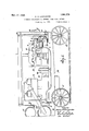
- FIG. 1 is a side elevation of a gasoline portable compressor unit equipped with a governor controlling mechanism
- FIG. 2 is an enlarged detail diagrammatic view of the governor controllin mechanism partly in section, with the relative position of some of the parts altered and brought into the same vertical planefor clearness of illustration.
- the invention is shown in connection with a portable compressor unit, in which the compressor A, mounted on the frame B having the wheels is driven gine D.
- the invention is applicable to stationary aswell as portable units.
- the air receiver E for the compressor, and gasoline tank F for the combustion engine, may be mounted in any suitable manner on the frame.
- the main driving shaft of the combustion engine D and the crank shaft G of the compressor, are coupled by any suitable coupling H.
- the compressor A discharges directly into the end of the receiver E by the usual discharge pipe.
- the combustion engine is provided with a suitable centrifugal governor mounted on the countershaft J suitably geared to the engine shaft K.
- the weighted governor arms L are pivoted on the spider O and are adapted to bear against the plate P, slidable on the countershaft J which in turn moves the lower end Q of the governor lever B outwardly about the pivotal point S as the governor arms fly outwardly with increase of speed of the engine.
- the upper end of the lever B is connected by a rod T to the throttle U of the combustion engine, so that upon an increase of s eed of the engine beyond a predetermined egree, the throttle U is automatically moved towards closed position and the speed brought back to the desired point.
- Means are provided for setting the governor whereby the speed of theengine may be limited to a predetermined maximum and predetermined by any suitable combustion enin this instance a compression spring V is held between the cap W on the lever B and the cap X on the end of the adjusting set screw Y, which in turn is mounted on a controller arm Z.
- the tension of the governor spring V determines the maximum speed of the engine.
- means are provided cooperating with the said setting device for reducing the operating speed of the engine through successive steps to a predetermined minimum, and this cooperating means is preferably manually operated.
- a controller bracket a is provided with an adjusting segment I) having a series of holes 0 corresponding to different speeds of the engine, and the controller arm Z carrying the set screw or adjusting device Y is pivoted at d on the bracket a.
- the controller lever e is pivoted on the bracket a at the point f, and is provided with a cam y cooperating with portions of the controller arm Z.
- a pin h in the outer end of the controller lever e is adapted to be inserted in the holes 0 in the segment I) to maintain the controller lever e in the desired position for a given speed of the engine.
- the bracket a is also provided with a spring ocket or socket j containing a spring is having a cap 0 bearing upon the controller arm Z, which tends to hold the controller arm upon the cam g of the controller lever 6.
- the governor spring V will be under maximum compression and the speed of the engine will be limited to a predetermined maximum.
- the controller lever 6 may be moved towards the o posite end q of the segment I) and adjuste in different holes 0 for reducing the operating speed of the engine through successive steps to a predetermined minimum, because in so moving the controller lever e, the controller arm Z will be adjusted by the cam (1 to relieve the compression of the governor sprin V, and a predetermined minimum speed 0? the engine will be obtained when the controller lever e is in the last hole 0 nearest the end I of the segment.
- the tension of the spring V may be varied and the predetermined speed for which the governor is set may be changed.
- automatic mechanism is also provided cooperating with the setting device for reducing the operating speed of the enwhich gine. -toa predetermined minimum,
- the controller bracket (2 is preferably provided with'an air cylinder 8, having a plunger 11 carrying a pin a adapted to bear against the toe o of the controller arm Z, so that air pressure behind the plun ger t will force the pin 14 against the toe v and rock the controller arm Z about its pivot d in a direction to relieve the tension of the governor spring V, regardless of the position at which the controller lever e is set.
- the air cylinder 8 is connected by a pipe w through any suitable auxiliary valve 00 to the receiver tank E.
- auxiliary valve m The function of the auxiliary valve m is like that of the valve described" in United States Patent No. 1,138,278 ranted May 4, 1915 to J. H. Castle and G. Rogers.
- the valve 9 At a certain predetermined receiver pressure the valve 9:, as disclosed in said patent, operates to admit such receiver pressure to the regulating mechanism, until the receiver pressure again falls a certain amount below that required to operate the valve, when the valve returns to its original position allowing the re lating mechanism to exhaust to atmospheric pressure.
- a branch pipe y preferably having a check valve 2 is connected to the ipe w to furnish fluid pressure for holding open the inlet valves of the compressor to permit unloading when the pressure in the receiver is too great.
- the inlet valves may be of any suitable construction, and in this instance are shown as plate valves 2, having valve cages 3 provided with air cylinders 4 having plungers 5 and fingers 6 connected to the plungers for lifting and holding the valves open when air pressure is admitted behind the plungers.
- the auxiliary valve :11 Upon a sufiicient increase of pressure in the discharge tank E, the auxiliary valve :11 will permit fluid pressure to pass to the air cylinders 4 of said valve lifters and also to the air 0 linder s of the governor controller, in whic case the compressor will be automatically unloaded because the inlet valves 2 will be held open and the engine speed will be automatically reduced to a predetermined degree, while the compressor is running unloaded. The compressor will automatically resume its load at the proper pressure due to the action of the valve an as well understood in the art, and the en ine will be brought back to operating spee
- the valve 00 is of standard construction but forms no part of the present invention.
- Means are also provided in connection with the governor controller for setting the automatic mechanism so that the minimum I speed of theengine willbe adjusted to any predetermined i into the spring I have found thatmygovernor controller operates satisfactorily and well and in a highly efiicient manner. When the various adjustments are once made they need not be altered under ordinary-conditions, but
- a unitary governor controller for regulating the operation of ajjicentrifugal governor having a governor spring, said controller, comprising a bracket adapted to be attached to an engine, a controller arm p1voted on said bracket, a device carried by and movable relatively to said controller arm for independently ad'usting the tension of the governor spring, w ereby the speed of the engine may be limited to a predeterm ned maximum without adjusting said controller arm, a pivoted controller lever and cam carried by the bracket for adjustin said controller arm, and means on the racket eooperating with said controller lever for holding the lever in different positions of adjustment.
- a unitary governor controller for regulating the-operation of a centrifugal governor having a governor spring, said controller comprising a bracket adapted to be attached to an engine, a controller arm pivoted on said bracket, a device carried by and movable relatively to said controller arm for independently adjusting the tension of the governor spring, whereby the speed of the engine may be limited to a predetermined maximum without adjusting said controller arm, a manually actuated pivoted controller lever and cam carried by the bracket for adjusting said controller arm, means on the bracket cooperating with said controller lever for holding the lever in different positions of adjustment, and resilient means for holding said controller arm. against said cam, whereby the controller arm follows the movement of the cam.
- said controller comprising a bracket adapted to be attached to an engine, a controller arm pivdevice carried by and movable relatively to said controller arm for independently adjusting the tension of the governor spring, whereby the speed of the engine may belimited to a predetermined maximum without adjusting said controller arm, a manually actuated ivoted controller lever and cam carried by t e bracket for adjusting said controller arm, means on the bracket cooperating with said controller lever for holding the lever in different positions of adjustment, resilient means for holding said controller arm against said cam whereby the controller arm follows the movements of the cam, and an adjustable stop for the controller arm carried by the bracket forming a mimmum speed stop whereby movement of the controller arm may be limited for adjusting the minimum speed of the engine.
- a unitary governor controller for regulating the operation of a centrifugal 'governor having a governor spring, said controller comprising a bracket adapted to be attached to an engine, a controller arm pivoted on said bracket, a device carried by and movable relatively to said controller arm for independently adjusting the tension of the governor spring, whereby the speed of the engine may be limited to a predetermined maximum without adjusting said controller arm, a pivoted controller lever and cam carried by the bracket for adjusting said controller arm, means on the bracket cooperating with said controller lever for holding the lever in different positions of adjustment, resilient means for holding said controller arm against the cam, and a cylinder on said bracket having a pressure fluid actuated plunger cooperating with said pivoted controller arm for automatically reducing the operating speed of the engine to a predetermined minimum.
- a unitary governor controller for regulating the operation of a centrifugal governor having a governor spring, said controller comprising a bracket adapted to be attached toan engine, a controller arm pivoted on said bracket, a device carried by and movable relatively to said controller arm for independently a justing the tension of the governor spring, whereby the speed of the engine may be limited to a predetermined maximum without adjusting said controller arm, a pivoted controller lever and cam carried by the bracket for adjusting said controller arm, means on the bracket cooperating with said controller lever for holding the lever in different positions of adjustment, resilient means for holding said controller arm against the cam, a cylinder on said bracket having a pressure fluid actuated plunger cooperating with said pivoted controller arm for automatically reducing the operating speed of the engine to a prede- 5 termined minimum, and an adjustable stop for the controller arm carried by the bracket forming a minimum speed stop, whereby movement of the controller arm may be limited for adjusting the minimum speed of the en ne.
Landscapes
- Engineering & Computer Science (AREA)
- Chemical & Material Sciences (AREA)
- Combustion & Propulsion (AREA)
- Mechanical Engineering (AREA)
- General Engineering & Computer Science (AREA)
- Control Of Throttle Valves Provided In The Intake System Or In The Exhaust System (AREA)
- High-Pressure Fuel Injection Pump Control (AREA)
Description
Nov. 17, 1925- 1,561,773
- A. 0. CARPENTER GOVERNOR CONTRQLLBR FOR INTERNAL COMBUSTION ENGINES 7 Filed Aug, L925 2heats-Sheet 1 N MN? is 5 (I: Q 8 8 INVENTOR H g Kllan afaqoenzen HIS ATTORNEY Nov. 17, 1925 A. O. CARPENTER GOVERNOR CONTROLLER FOR INTERNAL COMBUSTION ENGINES Filed Aug. 21. 1923 2 Sheets-Sheet 2 lnl Patented Nov. 17, 1925.
ALLAN o. CARPENTER, or ooanme,
column, or JERSEY CITY, NEW
NEW YORK, ASSIGNOR T INGERSOLL-RAND JERSEY, A CORPORATION OF NEW JERSEY.
GOVERNOR CONTROLLER FOR IN TERNAL-COMBUSTION ENGINES.
I Application filed August 21, 1923. Serial No. 658,598.
To all whom it may concern:
Be it known that I, ALLAN O. CARPENTER, a citizen of the United States, and a resident of Corning, county of Steuben, State of New York, have invented a certain Governor Controller for Internal-Combustion Engines, of which the--following is'a specifi cation accompanied by drawings.
This invention. relates to controlling mechanism for the governor of an internal combustion engine, but particularl to mechanism,for controlling the centri ugal governor of such an engine when used-for driving a compressor;
-In an ordinary combustion engine driven unit, even although equipped with a governor for the engine, the unit is operated at practically a constant, speed and when unloading of the compressor takes place there is a slight increase in the speed of the unit,
due to reduced load. Furthermore, it is not convenient to reduce the speed of the machine during operation in order to cut down the amount of air delivered in accordance with the demands, since this must be done by regulation ofthe hand throttle of the enine. 6 Such regulation takes the machine outof governor control as long. as air is being compressed, and if the engine has been throttled to a low speed and unloading occurs, the engine will immediately jump to its maximum speed as controlled by the governor.
Also, when operating under the throttled condition and without governor control, even though unloading does not tion is likely to be more or less unsteady, due to variations in the fuel supply and the other operating conditions. 7
The objects of the present invention are to enable the machine to be maintained under governor control at any operating speed, and when automatically unloaded to be antomatically reduced in speed to a minimum idling speed, but even in this condition still maintained under :governor control. The advantages of such operation are, others mentioned, that at no time is the maoccur, the operaohine runningat anexcessive speed, which greatly reduces the wear on the moving parts and reduces the fuel consum tion.
In addition to the features mentioned, an
object of the invention is to enable the operator to conveniently and promptly adjust I engine driven among the governor setting, whereby-the operating speed of the machine may be reduced through successive steps to a minimum While the engine is running.
The invention is shown in one of its preferred forms in the accompanying drawings, in which Figure 1 is a side elevation of a gasoline portable compressor unit equipped with a governor controlling mechanism, and
Figure 2 is an enlarged detail diagrammatic view of the governor controllin mechanism partly in section, with the relative position of some of the parts altered and brought into the same vertical planefor clearness of illustration.
Referring to the drawings, the invention is shown in connection with a portable compressor unit, in which the compressor A, mounted on the frame B having the wheels is driven gine D. The invention, however, is applicable to stationary aswell as portable units. The air receiver E for the compressor, and gasoline tank F for the combustion engine, may be mounted in any suitable manner on the frame. The main driving shaft of the combustion engine D and the crank shaft G of the compressor, are coupled by any suitable coupling H. The compressor A discharges directly into the end of the receiver E by the usual discharge pipe.
The combustion engine is provided with a suitable centrifugal governor mounted on the countershaft J suitably geared to the engine shaft K. The weighted governor arms L, in this instance, are pivoted on the spider O and are adapted to bear against the plate P, slidable on the countershaft J which in turn moves the lower end Q of the governor lever B outwardly about the pivotal point S as the governor arms fly outwardly with increase of speed of the engine. The upper end of the lever B is connected by a rod T to the throttle U of the combustion engine, so that upon an increase of s eed of the engine beyond a predetermined egree, the throttle U is automatically moved towards closed position and the speed brought back to the desired point.
Means are provided for setting the governor whereby the speed of theengine may be limited to a predetermined maximum and predetermined by any suitable combustion enin this instance a compression spring V is held between the cap W on the lever B and the cap X on the end of the adjusting set screw Y, which in turn is mounted on a controller arm Z. The tension of the governor spring V determines the maximum speed of the engine.
In accordance with one feature of the invention, means are provided cooperating with the said setting device for reducing the operating speed of the engine through successive steps to a predetermined minimum, and this cooperating means is preferably manually operated.
In the present instance, and as a convenient form of unitary governor controller adapted to be mounted on the combustion engine, a controller bracket a is provided with an adjusting segment I) having a series of holes 0 corresponding to different speeds of the engine, and the controller arm Z carrying the set screw or adjusting device Y is pivoted at d on the bracket a. The controller lever e is pivoted on the bracket a at the point f, and is provided with a cam y cooperating with portions of the controller arm Z. A pin h in the outer end of the controller lever e is adapted to be inserted in the holes 0 in the segment I) to maintain the controller lever e in the desired position for a given speed of the engine. The bracket a is also provided with a spring ocket or socket j containing a spring is having a cap 0 bearing upon the controller arm Z, which tends to hold the controller arm upon the cam g of the controller lever 6. When the controller lever e is adjusted nearest the end 7) of the segment I), the governor spring V will be under maximum compression and the speed of the engine will be limited to a predetermined maximum. From this setting the controller lever 6 may be moved towards the o posite end q of the segment I) and adjuste in different holes 0 for reducing the operating speed of the engine through successive steps to a predetermined minimum, because in so moving the controller lever e, the controller arm Z will be adjusted by the cam (1 to relieve the compression of the governor sprin V, and a predetermined minimum speed 0? the engine will be obtained when the controller lever e is in the last hole 0 nearest the end I of the segment. By looseninglthe adusting nut r on the set screw of: the governor setting device and adjusting the set screw Y, the tension of the spring V may be varied and the predetermined speed for which the governor is set may be changed.
In addition to the manual means for reducing the operating speed of the engine through successive steps to a predetermined minimum, automatic mechanism is also provided cooperating with the setting device for reducing the operating speed of the enwhich gine. -toa predetermined minimum,
may be equal to or below the minimum speed in accordance with the discharge pressure ofthe compressor and is intended to be brought into operation when the air discharge, pres sure exceeds a predetermined degree or when the compressor is running unloaded. For this purpose the controller bracket (2 is preferably provided with'an air cylinder 8, having a plunger 11 carrying a pin a adapted to bear against the toe o of the controller arm Z, so that air pressure behind the plun ger t will force the pin 14 against the toe v and rock the controller arm Z about its pivot d in a direction to relieve the tension of the governor spring V, regardless of the position at which the controller lever e is set. As shown, the air cylinder 8 is connected by a pipe w through any suitable auxiliary valve 00 to the receiver tank E. The function of the auxiliary valve m is like that of the valve described" in United States Patent No. 1,138,278 ranted May 4, 1915 to J. H. Castle and G. Rogers. At a certain predetermined receiver pressure the valve 9:, as disclosed in said patent, operates to admit such receiver pressure to the regulating mechanism, until the receiver pressure again falls a certain amount below that required to operate the valve, when the valve returns to its original position allowing the re lating mechanism to exhaust to atmospheric pressure. A branch pipe y preferably having a check valve 2, is connected to the ipe w to furnish fluid pressure for holding open the inlet valves of the compressor to permit unloading when the pressure in the receiver is too great. The inlet valves (only one of which is shown) may be of any suitable construction, and in this instance are shown as plate valves 2, having valve cages 3 provided with air cylinders 4 having plungers 5 and fingers 6 connected to the plungers for lifting and holding the valves open when air pressure is admitted behind the plungers. Upon a sufiicient increase of pressure in the discharge tank E, the auxiliary valve :11 will permit fluid pressure to pass to the air cylinders 4 of said valve lifters and also to the air 0 linder s of the governor controller, in whic case the compressor will be automatically unloaded because the inlet valves 2 will be held open and the engine speed will be automatically reduced to a predetermined degree, while the compressor is running unloaded. The compressor will automatically resume its load at the proper pressure due to the action of the valve an as well understood in the art, and the en ine will be brought back to operating spee The valve 00 is of standard construction but forms no part of the present invention.
Means are also provided in connection with the governor controller for setting the automatic mechanism so that the minimum I speed of theengine willbe adjusted to any predetermined i into the spring I have found thatmygovernor controller operates satisfactorily and well and in a highly efiicient manner. When the various adjustments are once made they need not be altered under ordinary-conditions, but
may be readily changed if desired. The
automatic mechanism will 0 erate under the conditions re uired for suc operation and the manual a justing device may be readily and conveniently ad usted while the engine is running, which is an important feature in addition to the advantages hereinbefore pointed out.
I claim: a p
1.. A unitary governor controller for regulating the operation of ajjicentrifugal governor having a governor spring, said controller, comprising a bracket adapted to be attached to an engine, a controller arm p1voted on said bracket, a device carried by and movable relatively to said controller arm for independently ad'usting the tension of the governor spring, w ereby the speed of the engine may be limited to a predeterm ned maximum without adjusting said controller arm, a pivoted controller lever and cam carried by the bracket for adjustin said controller arm, and means on the racket eooperating with said controller lever for holding the lever in different positions of adjustment.
2. A unitary governor controller for regulating the-operation of a centrifugal governor having a governor spring, said controller comprising a bracket adapted to be attached to an engine, a controller arm pivoted on said bracket, a device carried by and movable relatively to said controller arm for independently adjusting the tension of the governor spring, whereby the speed of the engine may be limited to a predetermined maximum without adjusting said controller arm, a manually actuated pivoted controller lever and cam carried by the bracket for adjusting said controller arm, means on the bracket cooperating with said controller lever for holding the lever in different positions of adjustment, and resilient means for holding said controller arm. against said cam, whereby the controller arm follows the movement of the cam.
33. A unitary governor controller for reguoted on said bracket, a
lating the operation of a centrifugal gov ernor having a governor spring, said controller comprising a bracket adapted to be attached to an engine, a controller arm pivdevice carried by and movable relatively to said controller arm for independently adjusting the tension of the governor spring, whereby the speed of the engine may belimited to a predetermined maximum without adjusting said controller arm, a manually actuated ivoted controller lever and cam carried by t e bracket for adjusting said controller arm, means on the bracket cooperating with said controller lever for holding the lever in different positions of adjustment, resilient means for holding said controller arm against said cam whereby the controller arm follows the movements of the cam, and an adjustable stop for the controller arm carried by the bracket forming a mimmum speed stop whereby movement of the controller arm may be limited for adjusting the minimum speed of the engine.
4. A unitary governor controller for regulating the operation of a centrifugal 'governor having a governor spring, said controller comprising a bracket adapted to be attached to an engine, a controller arm pivoted on said bracket, a device carried by and movable relatively to said controller arm for independently adjusting the tension of the governor spring, whereby the speed of the engine may be limited to a predetermined maximum without adjusting said controller arm, a pivoted controller lever and cam carried by the bracket for adjusting said controller arm, means on the bracket cooperating with said controller lever for holding the lever in different positions of adjustment, resilient means for holding said controller arm against the cam, and a cylinder on said bracket having a pressure fluid actuated plunger cooperating with said pivoted controller arm for automatically reducing the operating speed of the engine to a predetermined minimum.
5. A unitary governor controller for regulating the operation of a centrifugal governor having a governor spring, said controller comprising a bracket adapted to be attached toan engine, a controller arm pivoted on said bracket, a device carried by and movable relatively to said controller arm for independently a justing the tension of the governor spring, whereby the speed of the engine may be limited to a predetermined maximum without adjusting said controller arm, a pivoted controller lever and cam carried by the bracket for adjusting said controller arm, means on the bracket cooperating with said controller lever for holding the lever in different positions of adjustment, resilient means for holding said controller arm against the cam, a cylinder on said bracket having a pressure fluid actuated plunger cooperating with said pivoted controller arm for automatically reducing the operating speed of the engine to a prede- 5 termined minimum, and an adjustable stop for the controller arm carried by the bracket forming a minimum speed stop, whereby movement of the controller arm may be limited for adjusting the minimum speed of the en ne.
In testimony whereof I have signed this specification.
Priority Applications (2)
| Application Number | Priority Date | Filing Date | Title |
|---|---|---|---|
| US658598A US1561773A (en) | 1923-08-21 | 1923-08-21 | Governor controller for internal-combustion engines |
| US724243A US1550876A (en) | 1923-08-21 | 1924-07-05 | Governor controller for internal-combustion engines |
Applications Claiming Priority (1)
| Application Number | Priority Date | Filing Date | Title |
|---|---|---|---|
| US658598A US1561773A (en) | 1923-08-21 | 1923-08-21 | Governor controller for internal-combustion engines |
Publications (1)
| Publication Number | Publication Date |
|---|---|
| US1561773A true US1561773A (en) | 1925-11-17 |
Family
ID=24641900
Family Applications (1)
| Application Number | Title | Priority Date | Filing Date |
|---|---|---|---|
| US658598A Expired - Lifetime US1561773A (en) | 1923-08-21 | 1923-08-21 | Governor controller for internal-combustion engines |
Country Status (1)
| Country | Link |
|---|---|
| US (1) | US1561773A (en) |
Cited By (4)
| Publication number | Priority date | Publication date | Assignee | Title |
|---|---|---|---|---|
| US2823686A (en) * | 1952-04-17 | 1958-02-18 | Thompson Prod Inc | Turbine control |
| US2977805A (en) * | 1959-07-27 | 1961-04-04 | Caterpillar Tractor Co | Hydraulic decelerator for a spring balanced engine governor |
| US2986291A (en) * | 1957-07-09 | 1961-05-30 | Allis Chalmers Mfg Co | Fuel injection system |
| US3118308A (en) * | 1964-01-21 | Variable speed governor with throttle overrule mechanism |
-
1923
- 1923-08-21 US US658598A patent/US1561773A/en not_active Expired - Lifetime
Cited By (4)
| Publication number | Priority date | Publication date | Assignee | Title |
|---|---|---|---|---|
| US3118308A (en) * | 1964-01-21 | Variable speed governor with throttle overrule mechanism | ||
| US2823686A (en) * | 1952-04-17 | 1958-02-18 | Thompson Prod Inc | Turbine control |
| US2986291A (en) * | 1957-07-09 | 1961-05-30 | Allis Chalmers Mfg Co | Fuel injection system |
| US2977805A (en) * | 1959-07-27 | 1961-04-04 | Caterpillar Tractor Co | Hydraulic decelerator for a spring balanced engine governor |
Similar Documents
| Publication | Publication Date | Title |
|---|---|---|
| US2200892A (en) | Regulating device for compressed fluid generators of the free pistons type | |
| US2470366A (en) | Automatic spark advance mechanism | |
| US2879754A (en) | Protective starting device for internal combustion engines | |
| US2355759A (en) | Exhaust-driven turbosupercharger for internal-combustion engines | |
| US1561773A (en) | Governor controller for internal-combustion engines | |
| US2233035A (en) | Device for regulating the amount of fuel delivered to injection internal combustion engines | |
| US2546613A (en) | Controlling apparatus | |
| US1550876A (en) | Governor controller for internal-combustion engines | |
| US2435970A (en) | Free piston engine pressure control means | |
| US2171286A (en) | Compressor regulator | |
| US1906334A (en) | Fuel control system for oil engines | |
| US2036989A (en) | Internal combustion engine | |
| US2476048A (en) | Compressor control system | |
| US2595369A (en) | Governing mechanism for enginedriven compressors | |
| US2780209A (en) | Engine fuel delivery control | |
| US2473171A (en) | Automatic spark advance mechanism | |
| US2380226A (en) | Automatic compressor regulator | |
| US2479257A (en) | Vacuum operated governor for gas motors | |
| US1790443A (en) | X j jection type | |
| US2437883A (en) | Engine governor | |
| US2507415A (en) | Fuel control system for injection type internal-combustion engines | |
| US2789755A (en) | Compressor control system | |
| US2399080A (en) | Governor | |
| US2569664A (en) | Combined mechanical and pneumatic governor | |
| US2471111A (en) | Mechanism for utilizing the manifold suction of internal-combustion engines |