US1495994A - Metal-burning apparatus - Google Patents
Metal-burning apparatus Download PDFInfo
- Publication number
- US1495994A US1495994A US462914A US46291421A US1495994A US 1495994 A US1495994 A US 1495994A US 462914 A US462914 A US 462914A US 46291421 A US46291421 A US 46291421A US 1495994 A US1495994 A US 1495994A
- Authority
- US
- United States
- Prior art keywords
- arm
- cutting
- torch
- nozzle
- metal
- Prior art date
- Legal status (The legal status is an assumption and is not a legal conclusion. Google has not performed a legal analysis and makes no representation as to the accuracy of the status listed.)
- Expired - Lifetime
Links
Images
Classifications
-
- B—PERFORMING OPERATIONS; TRANSPORTING
- B23—MACHINE TOOLS; METAL-WORKING NOT OTHERWISE PROVIDED FOR
- B23K—SOLDERING OR UNSOLDERING; WELDING; CLADDING OR PLATING BY SOLDERING OR WELDING; CUTTING BY APPLYING HEAT LOCALLY, e.g. FLAME CUTTING; WORKING BY LASER BEAM
- B23K7/00—Cutting, scarfing, or desurfacing by applying flames
- B23K7/10—Auxiliary devices, e.g. for guiding or supporting the torch
- B23K7/105—Auxiliary devices, e.g. for guiding or supporting the torch specially adapted for particular geometric forms
- B23K7/107—Auxiliary devices, e.g. for guiding or supporting the torch specially adapted for particular geometric forms for cutting circles
Definitions
- the object'of my invention is to provide metal-cuttin implements, of the character indicated, with means, for enabling the operv ator to direct the flame of the torch in a true circle or circular curve while handling the torch in a substantially free-hand manner,
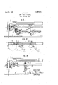
- Fig. 1 is a side elevational view, with parts in section, showing an attachment for cutting circles of relatively small radius
- Fig. 2 is a plan view of the construction shown in Fig.1?
- Fig. 3 is a side elevational View
- theopening to be cut is first outlined by scribing a circle on the surface of the metal it is possible for the operator, using a freehand torch, to follow the circle more or less closely, but even the most'experienced oper-- ators are unable to hold the flame accurately ennsylvania, have invented a new on the circle. The result is that such holes are cut out roughly and must be finished by a boring or milling" operation. Attempts have been made to guide the cutting torch 5 mechanically, the torch being mountedon a movable support which is operated in response to the movement of a guide member with'respect to a pattern or templet.
- the arm 4 carries a Centering device which, as shown, consists of a'clamp 10 having a slot 11 to receive the arm 4 and provided with a set-screw 12 for securing the clamp at any desired position of adjustment upon the arm 4.
- a pivot pin 13 is received in a socket 14 in the member 10 and is faste-ned adjustably therein by means of a setscrew 15. formed on the-arm 4 to indicate the proper setting of the centering. device for circles of difierent radii.
- the arm 4 may be made of, any convenient length, and the clamp 10 may either be attached from one side of the arm 4, as shown, or may extend through a slot cut lengthwise in the arm 4.
- the radius of the circle to be cut is determined and the clamp 10 is placed at the corresponding graduation on the arm 4.
- the center of the circle to be cut is preferably marked by means of a prickpunch or the like, and the pointed lower end of the pivot pin 13 is placed at this mark.-
- the torch is now ready to cut a complete and accurate circle, which the operator proceeds to do by simply turning the torch around the center piir 13. He guides the torch in a perfectly free-hand manner, but
- v is particularly designed for cutting circles of considerable size, which may vary from a few inches to several feet in diameter. It is not well suited for cutting very small circles for two reasons; First, because the necessary diameter of the bearing in which the nozzle is received limits the approach of the center clamp to the nozzle, and second,
- bracket 28 is offset so that when the clamp 28 is moved to its extreme position to the left against the casing 25 of the bearing 24, the pin 27 is directly beneath the axis of the center pin 30 which is then the axis Suitable graduations' may bepositions shown in this figure.
- each arm 26 of rotation of each arm 26.
- the clamps are placed at convenient points on the arm 21, aceording to the'nature of the work being cut.
- the radius of the circle described by the torch is fixed by the distance between the axis of the centering pin 27. and the axis of its corresponding pivot pin '30. This distance must of course be equal in the case of both centering pins, and the graduations on the arms 26 are so arranged that they show directly the correct distance between these axes. For example.
- Fig. 1 shows the implement set to cut a circle of inch radius.
- FIG. 2- The manner in which this form of my device operates is clearly shown in Fig. 2- where the implement is shown in the process of cutting acircle indicated by the dot-anddash line A.
- a portion B of the circle has already been cut and the arms 26 have swung about their individual center pins into the lhe axes of the pivot pins 30 of the bearings 24 describe circles indicated by the lines (l and it will be evident that the diameter of the circle A is exactly the same as the diameter of the circles C.
- the arms 21 be provided with means for.- temporarily moving the torch nozzle 3 a short distance toward or away. from the center pins 13 and 27 at the beginning of the cutting operation, so that if a circular hole is'being cut the outer edge of the opening first made will be in correct alignment with the circle, and when a circulardisc is being cut from a blank the inner edge of the opening first made is in correct line with the remainder of the circle.
- the end of the arm 4 or21 is provided with means for.- temporarily moving the torch nozzle 3 a short distance toward or away. from the center pins 13 and 27 at the beginning of the cutting operation, so that if a circular hole is'being cut the outer edge of the opening first made will be in correct alignment with the circle, and when a circulardisc is being cut from a blank the inner edge of the opening first made is in correct line with the remainder of the circle.
- a socket 21 having slots 31 which receive pins 32 carried by a short arm 33 that is attached directly to the hearing which carries the torch nozzle.
- An opening 34 is formed above the socket 21 and a pin carried by a spring finger 36 extends through the opening 34 and into engagement with the arm 'When the apparatus is in its normal cutting position the-pin 35 enters a depression 37 in the top of thearm 33..
- VVhenthe first hole is burned through the work, the operator pulls or pushes the torch sufiiciently to cause the spring-pressed pin 35 to snap back into the depression l, and the torch is then ready to continue cutting the circle.
- the device shown in Fig. 1 may be operated to out large circleshy taking oi'f one of the clamps 22, with its attachments, and moving the remaining pivot pin 27 up to its pivot hearing 25, which brings the pivot pins 27 and 80 into alinement.
- the device of Fig. 1 resembles that shown in Fig. 3, and operates in exactly the same way.
- the supporting arm 21 may be provided with graduations similar to those provided in the arm 4 in Fig. 3.
- my copending application for Letters Patent, Serial No. 462,913, filed April 20, 1921 I have described and claimed, both hroadly and specifically, a device for holdmg and guiding cutting torches in predetermined paths.
- the present application covers the specific means for cutting circles and circular curves and is included within the scope of the broad claims of application No. 462.913.
- An attachment for metal-cutting torches toinprising an antl-il'lClSlOD hearing provided .KTilIll a seat for receiving the nozzle of the torch, an arm extending laterally from the said bearing and provided with a series of graduations, a pivot pin having a pointed end for engagement with the work, means foradjustably securing the said centering pin to the said arm, and means for efl'ecting refinement of radial adjustment ofsaid nozzle independent of the pivot adjusting means.
- An attachment for metaLcutting torches comprising a bearing for rotatably receiving the nozzle of the torch, an arm adjustably extending laterally from the said bearing, a plurality of hearings adjustably secured to the said arm, a bearing carried by each of the said members, a graduated arm extending laterally from each of the said hearings, and a pivot pin adjustably carried by each of the said graduated arms.
- An attachment for metal cutting torches comprising a bearing for rotatahly receiving the nozzle ofthe torch, an arm extending laterally from the said bearing, a. plurality of bearings adjustably mounted on the said arm, graduated arms extending from each of-the said last-named bearings, a pivot pin adjustably carried by each of the said graduated arms, and means for effecting refinement of adjustment between said nozzle bearing and said first bearing.
- An attachment for metal cutting torches comprising a bearing for rotatably receiving the nozzle of the torch, an adjustable member extending laterally from the said bear-. ing, a plurality .of bearings adjustably mounted on the said arm, graduatedarms extending from each of the said last-named hearings, and'acentering pivot pin adjustably carried by each of the said graduated arms, each'of the said bearings carrying the said graduated arms comprising a central pivot in forming anaxis of rotation for the saig graduated arm, and each of the said centering pins being carried in a bracket adaptedv to position the said centering pin in alignment with the axis of the said pivot pin when the said bracket is in its position nearest to the axis of the said graduated arm.
- An attachment for metal-cutting torches comprising movable means v for holding the nozzle of a cutting torch, adjustable means for directing the movement of the said holding; means, and means for temporarily changing the position ofthe said holding means with respect to the said directing means at the beginning of the cutting opera.- tion.
- An attachment for metal-cutting torches comprising movable means for holding the nozzle of a cutting torch, adjustable means for directing the movement of the said holding means in a circular path, and means for moving the said holding means temporarily toward or away from'the axis of the said circular movement at the beginning of the cutting operation and for thereafter fixing the said holding means in normal cutting p0- sition.
- An attachment for metal-cutting torches comprising a bearing for receiving the nozzle of a cutting torch, an arm extending laterv & 1,495,994
- the said connecting means compris- In testimony whereof, I the said JAMES ing a socket carried by one of said parts, an F ARMER have hereunto set m hand.
Landscapes
- Physics & Mathematics (AREA)
- Geometry (AREA)
- Engineering & Computer Science (AREA)
- Mechanical Engineering (AREA)
- Arc Welding In General (AREA)
Description
June 3, 1924; 1,495,994
J. FARMER METAL BURNING APPARATUS Filed April 20. 1921 2 I FHA l tion 1;
f new JAMES BARKER, 0F PITTSBURGH, PENNSYLVANIA, ASSIGNOB OF ONE- EUGENE R0 ran'raL-Bunmnc are 5-:
, 0E PITTSBURGH, PENNSYLVANIA.
TUS.
Application filed April 20, 1921. Serial No. 462,914.
'0 all whom it concern: Be it known that I, JAMns FAnrmn, a citlzen of the United States, and resident of Pittsbur h, in the county of Allegheny and State of and useful Improvement in Metal-Burning Apparatus; and I do hereby declare the fol owing to be a full, clear, and exact descripereof. 4 J My invention relates to metal-cutting torches and similar implements for cutting metals by the use of oxyhydrogen .flames and the like. I I
The object'of my invention is to provide metal-cuttin implements, of the character indicated, with means, for enabling the operv ator to direct the flame of the torch in a true circle or circular curve while handling the torch in a substantially free-hand manner,
and to provide means for adjusting the radius of the. circles and curves so described by the flame.
With these and other objects in view, as will more clearly be shown below, my inven tion provides an attachment which may be applied to standard forms of cutting-torches without changing the construction of the torch, andwhich is of simple and durable construction. Two examples of my new attachments are shown in the accompanying drawing, in which Fig. 1 is a side elevational view, with parts in section, showing an attachment for cutting circles of relatively small radius; Fig. 2 is a plan view of the construction shown in Fig.1? and Fig. 3 is a side elevational View,
with parts in section, showing asim le form of construction which is especially intended for use in cutting circles of relatlvely large diameter. v p
In cutting steel plates, structural shapes and the like by means of cutting-torches, it
is often necessary to cut circular openings of various diameters, and this has heretofore been a matter of considerable difiiculty. If
.theopening to be cut is first outlined by scribing a circle on the surface of the metal it is possible for the operator, using a freehand torch, to follow the circle more or less closely, but even the most'experienced oper-- ators are unable to hold the flame accurately ennsylvania, have invented a new on the circle. The result is that such holes are cut out roughly and must be finished by a boring or milling" operation. Attempts have been made to guide the cutting torch 5 mechanically, the torch being mountedon a movable support which is operated in response to the movement of a guide member with'respect to a pattern or templet. Such machines, while capable of accurate work, are necessarily complicated and expensive, and have the further disadvantage that the .work must be brought to the machineand the machine carefully adjusted before beginning the cutting operation. that for many kinds of work it is cheaperandmore satisfactory to out the circular holes roughly and finish them afterward. For all of these reasons the cutting of circular holes with cutting-torches has always, 7 been considered a troublesome and expensive matter. I r According to my present invention I attach to the nozzle of, an ordinary cuttingtorch a device which, in its simplest form 7 consists of an arm having one end rotatably attached to the nozzle of the torch, andcarrying a center pin or axis pin which is adjustable both asto its height-and as to its p0 sition on the arm. This simple form of applying my invention is shown'in Fig. 3 of d the drawing. F or cuttin small circles I prefer to use the form 0 Figs. 1 and 2, where the arm carries two separate members which are independently provided with able internal diameter to receive the nozzle 3 and provided on its outer surface with screw threads that are received in an internally i013 screw-threaded sleeve 7 forming part of the bearing 5.. By adjusting the sleeve. 6 with- Iii The result is 65 v respect to the bearing 5 the position of the lower end of the torch above the work 8 may be varied as desired.
The arm 4 carries a Centering device which, as shown, consists of a'clamp 10 having a slot 11 to receive the arm 4 and provided with a set-screw 12 for securing the clamp at any desired position of adjustment upon the arm 4. A pivot pin 13 is received in a socket 14 in the member 10 and is faste-ned adjustably therein by means of a setscrew 15. formed on the-arm 4 to indicate the proper setting of the centering. device for circles of difierent radii. The arm 4 may be made of, any convenient length, and the clamp 10 may either be attached from one side of the arm 4, as shown, or may extend through a slot cut lengthwise in the arm 4. p
In operation, the radius of the circle to be cut is determined and the clamp 10 is placed at the corresponding graduation on the arm 4. The center of the circle to be cut is preferably marked by means of a prickpunch or the like, and the pointed lower end of the pivot pin 13 is placed at this mark.- The torch is now ready to cut a complete and accurate circle, which the operator proceeds to do by simply turning the torch around the center piir 13. He guides the torch in a perfectly free-hand manner, but
the irregularities due to ordinary free-hand cutting are entirely eliminated.
As stated above. the simple form of my device, shown in Fig. 3 and just described,
v is particularly designed for cutting circles of considerable size, which may vary from a few inches to several feet in diameter. It is not well suited for cutting very small circles for two reasons; First, because the necessary diameter of the bearing in which the nozzle is received limits the approach of the center clamp to the nozzle, and second,
because the center pin 13, when brought close to the flame, is likely to be burned an d'dainaged. I therefore prefer to employ for cutting small circles the attachment shown in Figs. 1 and 2, where the nozzle 3 of the torch 2 is received in a simple swivel bearing 20 formed at one end of anarm 21. corresponding to the arm 4 of Fig. 3. Adjustably mounted on the. arm 21. are two clamps 22 provided with set-screws 23 and carrying ball hearings or other anti-friction bearings 24. These bearings 24 include outer sleeves 25 from which extend graduated arms 26, each of which carries a centering pin 27 that is preferably held adjustable in a bracket 28 secured to thearm 26 by means of a set-screw 29. It will be observed that the bracket 28 is offset so that when the clamp 28 is moved to its extreme position to the left against the casing 25 of the bearing 24, the pin 27 is directly beneath the axis of the center pin 30 which is then the axis Suitable graduations' may bepositions shown in this figure.
, of rotation of each arm 26. I prefer to provide two of these sets of bearings and centering pins, as shown, in order that the supthe arm 21 .are not of special importance.
as these positions have nothing to do with the radius of the circle which is described by the cutting torch 2. Therefore, the clamps are placed at convenient points on the arm 21, aceording to the'nature of the work being cut. The radius of the circle described by the torch is fixed by the distance between the axis of the centering pin 27. and the axis of its corresponding pivot pin '30. This distance must of course be equal in the case of both centering pins, and the graduations on the arms 26 are so arranged that they show directly the correct distance between these axes. For example.
Fig. 1 shows the implement set to cut a circle of inch radius.
The manner in which this form of my device operates is clearly shown in Fig. 2- where the implement is shown in the process of cutting acircle indicated by the dot-anddash line A. A portion B of the circle has already been cut and the arms 26 have swung about their individual center pins into the lhe axes of the pivot pins 30 of the bearings 24 describe circles indicated by the lines (l and it will be evident that the diameter of the circle A is exactly the same as the diameter of the circles C.
At the beginning of the cutting operation the first hole that is cut through the work by the flame of the torch is of larger diameter than the width of the slot which is afterwards cut on account of the longer time at the starting point. For this reason I prefer that the arms 21 be provided with means for.- temporarily moving the torch nozzle 3 a short distance toward or away. from the center pins 13 and 27 at the beginning of the cutting operation, so that if a circular hole is'being cut the outer edge of the opening first made will be in correct alignment with the circle, and when a circulardisc is being cut from a blank the inner edge of the opening first made is in correct line with the remainder of the circle. For this purpose the end of the arm 4 or21. as the case may be, is provided with a socket 21 having slots 31 which receive pins 32 carried by a short arm 33 that is attached directly to the hearing which carries the torch nozzle. An opening 34 is formed above the socket 21 and a pin carried by a spring finger 36 extends through the opening 34 and into engagement with the arm 'When the apparatus is in its normal cutting position the-pin 35 enters a depression 37 in the top of thearm 33..
that the flame is in contact with the metal comprising a hearing for the'nozzle of the .iaeaeee when they reach the end of the slot 31.-
VVhenthe first hole is burned through the work, the operator pulls or pushes the torch sufiiciently to cause the spring-pressed pin 35 to snap back into the depression l, and the torch is then ready to continue cutting the circle.
The device shown in Fig. 1 may be operated to out large circleshy taking oi'f one of the clamps 22, with its attachments, and moving the remaining pivot pin 27 up to its pivot hearing 25, which brings the pivot pins 27 and 80 into alinement. As thus arranged, the device of Fig. 1 resembles that shown in Fig. 3, and operates in exactly the same way. For this purpose, the supporting arm 21 may be provided with graduations similar to those provided in the arm 4 in Fig. 3. In my copending application for Letters Patent, Serial No. 462,913, filed April 20, 1921, I have described and claimed, both hroadly and specifically, a device for holdmg and guiding cutting torches in predetermined paths. The present application covers the specific means for cutting circles and circular curves and is included within the scope of the broad claims of application No. 462.913.
It will be understood that various changes in the form and arrangement of parts may readily be made without departing from my invention, I therefore desire that no limitations be imposed on my invention except such as are indicated in the appended claims.
I claim as my invention: 1. An attachment for metal-cutting torches torch, an arm extending laterally from the said hearing and provided with a series of graduations, a pivot memher carried by said laterally extending arm, means for securlng the said pivot member adjustably upon the said arm, and means independent of said pivot adjusting means for eflecting change in radius of said arm.
2. An attachment for metal-cutting torches toinprising an antl-il'lClSlOD hearing provided .KTilIll a seat for receiving the nozzle of the torch, an arm extending laterally from the said bearing and provided with a series of graduations, a pivot pin having a pointed end for engagement with the work, means foradjustably securing the said centering pin to the said arm, and means for efl'ecting refinement of radial adjustment ofsaid nozzle independent of the pivot adjusting means.
3. An attachment for metaLcutting torches comprising a bearing for rotatably receiving the nozzle of the torch, an arm adjustably extending laterally from the said bearing, a plurality of hearings adjustably secured to the said arm, a bearing carried by each of the said members, a graduated arm extending laterally from each of the said hearings, and a pivot pin adjustably carried by each of the said graduated arms. I
4. An attachment for metal cutting torches comprising a bearing for rotatahly receiving the nozzle ofthe torch, an arm extending laterally from the said bearing, a. plurality of bearings adjustably mounted on the said arm, graduated arms extending from each of-the said last-named bearings, a pivot pin adjustably carried by each of the said graduated arms, and means for effecting refinement of adjustment between said nozzle bearing and said first bearing.
5. An attachment for metal cutting torches comprising a bearing for rotatably receiving the nozzle of the torch, an adjustable member extending laterally from the said bear-. ing, a plurality .of bearings adjustably mounted on the said arm, graduatedarms extending from each of the said last-named hearings, and'acentering pivot pin adjustably carried by each of the said graduated arms, each'of the said bearings carrying the said graduated arms comprising a central pivot in forming anaxis of rotation for the saig graduated arm, and each of the said centering pins being carried in a bracket adaptedv to position the said centering pin in alignment with the axis of the said pivot pin when the said bracket is in its position nearest to the axis of the said graduated arm.
6. An attachment for metal-cutting torches comprising movable means v for holding the nozzle of a cutting torch, adjustable means for directing the movement of the said holding; means, and means for temporarily changing the position ofthe said holding means with respect to the said directing means at the beginning of the cutting opera.- tion.
' 7. An attachment for metal-cutting torches comprising movable means for holding the nozzle of a cutting torch, adjustable means for directing the movement of the said holding means in a circular path, and means for moving the said holding means temporarily toward or away from'the axis of the said circular movement at the beginning of the cutting operation and for thereafter fixing the said holding means in normal cutting p0- sition.-
8. An attachment for metal-cutting torches comprising a bearing for receiving the nozzle of a cutting torch, an arm extending laterv & 1,495,994
adjustably carried by the said arm and ,tion between the limits of its said lengthwise means for connecting the said arm to the said movement. 10
bearing, the said connecting means compris- In testimony whereof, I the said JAMES ing a socket carried by one of said parts, an F ARMER have hereunto set m hand.
5 arm carried by the other part and extending JAME FARMER.
into said socket and having a limited length- Witnesses: wise movement therein, and a spring-pressed EDITH K. FREESE, pin adapted to hold the'said arm in a posi- JoHN F. WILL,
Priority Applications (1)
| Application Number | Priority Date | Filing Date | Title |
|---|---|---|---|
| US462914A US1495994A (en) | 1921-04-20 | 1921-04-20 | Metal-burning apparatus |
Applications Claiming Priority (1)
| Application Number | Priority Date | Filing Date | Title |
|---|---|---|---|
| US462914A US1495994A (en) | 1921-04-20 | 1921-04-20 | Metal-burning apparatus |
Publications (1)
| Publication Number | Publication Date |
|---|---|
| US1495994A true US1495994A (en) | 1924-06-03 |
Family
ID=23838229
Family Applications (1)
| Application Number | Title | Priority Date | Filing Date |
|---|---|---|---|
| US462914A Expired - Lifetime US1495994A (en) | 1921-04-20 | 1921-04-20 | Metal-burning apparatus |
Country Status (1)
| Country | Link |
|---|---|
| US (1) | US1495994A (en) |
Cited By (9)
| Publication number | Priority date | Publication date | Assignee | Title |
|---|---|---|---|---|
| US2452718A (en) * | 1944-07-24 | 1948-11-02 | Blythe James Henry | Cutting torch holder |
| US2512235A (en) * | 1947-03-07 | 1950-06-20 | William K Lankford | Beam compass |
| US2670789A (en) * | 1949-03-02 | 1954-03-02 | Dieterich Charles | Acetylene torch with angularly adjustable tip |
| US2688190A (en) * | 1950-05-06 | 1954-09-07 | Jerry R Hayes | Acetylene cutting torch compass |
| US2743101A (en) * | 1952-12-30 | 1956-04-24 | Shirley E Clark | Device for guiding cutting torches |
| US4283043A (en) * | 1979-10-12 | 1981-08-11 | Alan Kalian | Cutting torch attachment |
| US20070125754A1 (en) * | 2005-12-07 | 2007-06-07 | John Nash | Multipurpose track and radius plate burner system |
| US20160158899A1 (en) * | 2008-03-14 | 2016-06-09 | Illinois Tool Works Inc. | Positioning attachment for a welding torch |
| US20230339036A1 (en) * | 2022-04-24 | 2023-10-26 | James Bouman | Positioning attachment for welding torch |
-
1921
- 1921-04-20 US US462914A patent/US1495994A/en not_active Expired - Lifetime
Cited By (11)
| Publication number | Priority date | Publication date | Assignee | Title |
|---|---|---|---|---|
| US2452718A (en) * | 1944-07-24 | 1948-11-02 | Blythe James Henry | Cutting torch holder |
| US2512235A (en) * | 1947-03-07 | 1950-06-20 | William K Lankford | Beam compass |
| US2670789A (en) * | 1949-03-02 | 1954-03-02 | Dieterich Charles | Acetylene torch with angularly adjustable tip |
| US2688190A (en) * | 1950-05-06 | 1954-09-07 | Jerry R Hayes | Acetylene cutting torch compass |
| US2743101A (en) * | 1952-12-30 | 1956-04-24 | Shirley E Clark | Device for guiding cutting torches |
| US4283043A (en) * | 1979-10-12 | 1981-08-11 | Alan Kalian | Cutting torch attachment |
| US20070125754A1 (en) * | 2005-12-07 | 2007-06-07 | John Nash | Multipurpose track and radius plate burner system |
| WO2007067749A2 (en) * | 2005-12-07 | 2007-06-14 | John Nash | Multipurpose track and radius plate burner system |
| WO2007067749A3 (en) * | 2005-12-07 | 2007-11-22 | John Nash | Multipurpose track and radius plate burner system |
| US20160158899A1 (en) * | 2008-03-14 | 2016-06-09 | Illinois Tool Works Inc. | Positioning attachment for a welding torch |
| US20230339036A1 (en) * | 2022-04-24 | 2023-10-26 | James Bouman | Positioning attachment for welding torch |
Similar Documents
| Publication | Publication Date | Title |
|---|---|---|
| US1495994A (en) | Metal-burning apparatus | |
| US3039244A (en) | Tool grinding fixture | |
| US1397696A (en) | Drilling attachment for milling-machines | |
| US3835541A (en) | Ellipsoid marker and template tracer | |
| US2098838A (en) | Work locating indicator for jig boring machines | |
| US1195248A (en) | Tool-gbinding attachment | |
| US2000476A (en) | Tool setting gauge | |
| US2551747A (en) | Drafting apparatus | |
| US1660616A (en) | Universal marking machine | |
| US4351111A (en) | Machine tool for scribing arcs and circles | |
| US2107051A (en) | Bushing locating and rotating means | |
| US2243778A (en) | Glass cutter | |
| US1217572A (en) | Metal-working apparatus. | |
| US1513883A (en) | Machine for forming lens-grinding tools | |
| US4268959A (en) | Pipe cutter | |
| US2224242A (en) | Small hole cutting attachment for blowpipes | |
| US2623285A (en) | Pipe-cutting machine | |
| US2523237A (en) | Torch-guiding tool | |
| US2472570A (en) | Work-supporting adjustable mandrel for band saws | |
| US2130575A (en) | Drill point locator | |
| US950175A (en) | Gage. | |
| US868074A (en) | Shaft liner and leveler. | |
| US1616150A (en) | Work support | |
| US2542473A (en) | Cutting torch holder | |
| US1216470A (en) | Setting gage for prong-cutting machines. |