US1489342A - Candy machine - Google Patents
Candy machine Download PDFInfo
- Publication number
- US1489342A US1489342A US564531A US56453122A US1489342A US 1489342 A US1489342 A US 1489342A US 564531 A US564531 A US 564531A US 56453122 A US56453122 A US 56453122A US 1489342 A US1489342 A US 1489342A
- Authority
- US
- United States
- Prior art keywords
- electric
- heating element
- head
- candy
- annular
- Prior art date
- Legal status (The legal status is an assumption and is not a legal conclusion. Google has not performed a legal analysis and makes no representation as to the accuracy of the status listed.)
- Expired - Lifetime
Links
Images


Classifications
-
- A—HUMAN NECESSITIES
- A23—FOODS OR FOODSTUFFS; TREATMENT THEREOF, NOT COVERED BY OTHER CLASSES
- A23G—COCOA; COCOA PRODUCTS, e.g. CHOCOLATE; SUBSTITUTES FOR COCOA OR COCOA PRODUCTS; CONFECTIONERY; CHEWING GUM; ICE-CREAM; PREPARATION THEREOF
- A23G3/00—Sweetmeats; Confectionery; Marzipan; Coated or filled products
- A23G3/02—Apparatus specially adapted for manufacture or treatment of sweetmeats or confectionery; Accessories therefor
- A23G3/10—Candy-pulling machines ; Processes or apparatus for making cotton candy or candy floss
Definitions
- My invention relates to cand machines emp oying a rotative vessel in w iich the ingredients of the candy are placed and heated to reduce the same to molten state and from which they are ejected by centrifugal force in threadlike filaments to produce so-called candy floss.
- Fig. 1 is a front elevation of my improved device, with the bowl partly broken away for the exposure of the interior of the same;
- Fig. 2 1s a vertical axial section of the game, taken in the plane of the line 22 of Fig. 3 is an enlarged vertical axial section of the upper end of the machine, partly broken away, taken in the plane of the line 3-3 of Fig. 2;
- Fig. 4 is a detail of the commutator end of the electric motor, taken in vertical axial section in the plane of the line 4-4 of Fig. 2;
- ig. 5 is a vertical axial section of a detail of the brush-stands, taken in the plane of the line 55 of Fig. 6.
- Fig. 6 is a cross-section of the same, taken in the plane of the line 6-6 of Fig. 2;
- Fig. 7 is a horizontal cross-section of my improved device, taken on the line 7-7 of Fig. 2. and showing the rheostat for the electric connections of the electric motor;
- Fig. 8 is a horizontal cross-section of my improved device, taken on the line 88 of Fig. 2, and showing the rheostat in the electric connections for the heating circuit;
- Fig. 9 is a diagrammatic representation of the electric circuits
- Fig. 10 is a plan view of the upper end of my improved device, partly broken away;
- Fig. 11 is a side elevation of the head, partly broken away;
- Fig. 12 is a detail of the heating element in the vessel, taken in horizontal section on the line 1212 of Fig. 11;
- Fig. 13 is a cross-sectional detail of the same, partly broken away;
- My im roved device is intended to convert can y ingredients, which may, for instance, be ordinary granulated sugar. or other ingredients, into silk-like threads to produce so-called candy floss.
- the ingredients are introduced into a vessel 21, the peripheral wall 22 of which is provided with openings 23, the vessel being provided with an electric heating element 24.
- the ingredients are placed in the vessel through an opening 25.
- the vessel is rotated, and while being rotated heat is supplied to the ingredients by means of the heating element, whereby the ingredients adjacent to the heating element are caused to melt and to be projected by centrifugal force, due to the rotation of the vessel, through interstices in the heating element and openings in the periphery of the vessel, to produce the silk-like strands of the candy lloss.
- Means are provided for independently regulating the heat of the heating element, and also for independently regulating the speeds of rotation of the. vessel, so that the heat as well as the speed of the heating element may be independently regulated throughout the course of producing the candy floss, in order to provide the necessary amount of heat and the necessary speed of rotation, as the condition of the candy floss being ejected may suggest.
- the frame of the machine preferably comprises a base 31 on which there is a pedestal 32, releasably secured to the base by screws 34.
- the pedestal may comprise a releasable top 35, held to the pedestal proper by bolts 36 and nuts 37, 38.
- the pedestal preferably comprises the casing of an electric motor 41.
- his motor is in upright position, its rotating armature 1:2 being in upright position and comprising an armature shaft 43 journaled in bearings 4-1, 45.
- the commutator 46 of the electric motor has suitable brushes 47 complemental thereto.
- An insulating spool 51 is supported on the pedestal. preferably; in spaced relation thereto, for instance, y having stems 52 threaded into the upper end of the pedestal, as shown at 53, the insulating spool being supported on the tops of these stems and secured thereto by screws 54.
- the upright shaft extends upwardly through the bore 55 of the spool, and has an upward extension 56.
- a head is secured to the upward extension of the shaft, preferably in readily releasable relation.
- This head comprises the vessel 21 and a downwardly extending por tion to which the vessel is secured, the downwardly extending portion being received over the upper end of the shaft and having )ortions of the electric connections for the eating element in the vessel thereon.
- the downward extension comprises a bushing 61. the lower end of which is provided with slots (32 to form fingers 63 frictionally contacting the shaft and frictionallv holding the head tothe shaft, and providing for ready upward removal of the head and ready attaching of the head about the shaft.
- This bushing which may he of metal, is provided with an annular flange 64, forming an annular shoulder 65 at its top and an annular shoulder 66 at its bottom.
- End insulating sleeves 67, 68, and an intermediate insulating sleeve 69 are received about the bushing and preferably have annular spaces 71, 72, between them.
- the upper insulating sleeve is provided with an annular shoulder 75
- the lower insulating sleeve is provided with an annular shoulder 76
- the intermediate insulating sleeve is rovided with an annular rib 77, forming annular shoulders respectively at. its top and at its bottom.
- Rings 80, 81 are received in the annular recesses formed respectively between the upper annular shoulder and the rib, and between the rib and the lower annular shoulder. These rings are clectro-conductive contact-rings.
- the rings and the sleeves are clampingly secured to the bushing by means of a nut 82 threaded about the lower threaded end 83 of the bushing for clamping the insulating sleeves with the contact-rings therebetween, between the shoulder 66 and the nut.
- a pair of brush-stands 85 are provided with brushes 86, arranged to contact the contact-ring 80.
- a pair of brush-stands 87 are provided with brushes 89. arranged to contact the contact-ring 81.
- the brush-stands 85 are the longer of the brush-stands to coact with the upper contact-ring, and the brush-stands 87 are the shorter brush-stands to enact with the lower contact-ring.
- the longer brush-stands 85 are secured to the insulating spool 51 by means of screws 91 and nuts 92, the screws and nuts also acting as binding posts.
- the shorter brushstands are secured to the insulating spool 51 by means of screws 93 and nuts 94, the screws and nuts also serving as binding posts.
- the upper end of the bushing 61 is threaded, as shown at 96, and has a nut 97 received thereover, the nut arranged to contact the shoulder 65.
- the vessel 21 comprises an uper plate 101 and a lower plate 102.
- the ower plate is provided with a central depression 103, at the bottom of which there is an inwardly extending radial flange 104, arranged to rest upon the nut 97.
- a second nut 105 is threaded over the threaded end of the bushing and is arranged to clamp the flange 104 between said nuts and to center said lower plate about the bushing.
- the upper plate is provided with the central opening 25, through which the charge of ingredients or sugar is arranged to be passed into the vessel.
- the upper plate is provided with an upwardly slanting central wall 109, at the upper end of which the opening 25 is located. this wall slanting downwardly and outwardly from the opening in order to lead the charge being supplied toward the periphery of the vessel, in case the centrifugal force of the rotating vessel acts upon the charge while being sup plied.
- the upper plate and the lower plate are respectively provided with outwardlv extending annular bends 111, 112. to form annular rabbets 113, 114-, between said plates.
- the peripheral wall 22 is formed by an annular peripheral plate located between the upper plate and the lower plate, preferably at the edges of the latter, this peripheral late being rovided with the openings 23, iown exten ing slantingly across said outer peripheral p ate.
- This peripheral plate is preferably rovided with inwardly radially extending anges 115, 116, respectively at the top and at the bottom of the peripheral late.
- These flanges and the u per and ower edges of the peripheral plate are located in the annular rabbets
- the peripheral plate is preferably provided with slanting edges 117, 118, at its top and bottom, referably located respectively above and elow said opening.
- Annular lips 119, 120 are preferably located at the outside of the peripheral plate at the top and at the bottom of the latter, shown formed by bending the peripheral edges of the upper plate and the lower plate respectively.
- This construction forms an annular mouth for the rotating vessel, which has a tendency to cause the candy floss to spread up and down as the same is eljected by centrifugal force from the vesse
- the eripheral plate and its flanges are preferably formed as an annular structure, the respective ends whereof are connected by providing a tongue 121 at one end of said structure received through openings 23 adjacent the other end of said structure, the end of said tongue being bent as a clip 122 upon the wall between said openings.
- Nuts 123 and bolts 124 are arranged to draw the upper plate and lower plate toward each other, and thereby clamp the peripheral member between them.
- An annular heating element 24 is provided for the head, and is shown formed up out of a strip of electric resistance ma.- terial provided with a suitable insulating coating 128, and bent as a flat spiral structure to form downwardly slanting stretches 129 and upwardly slanting stretches 130, slanting with relation to each other and connected at their tops and bottoms by reverse bends in the strip.
- the res ective ends of the strip are respectively ocated in and positioned in spaced relation by a block 132 of insulating material. the ends of the strip extending toward the middle of the vessel as electric conductors 133, 134, where electric connection is made with the same.
- the stretches of the heating element have narrow slots 135, 136, between them, which register at portions of their heights and form apertures through which the molten candy is projected, numbers of these apertures coinciding with the openings 23 in the peripheral plate.
- the heating element is flexible and 1s annularly received '.;at the inside of the peripheral plate, being preferably located in the peripheral plate structure. The centrifuge force acting upon the heating element during the rotation of the vessel causes the heating element to be urged toward said peripheral plate and to be held by said peripheral plate.
- Electric current is supplied to the device from a suitable source of electric energy by means of the electric conductors 141, 142, releasably connecting with the electric connections 143, 144, by means of a suitable electric lug 145.
- the e ectric conductor 143 is electrically connected with electric conductors 146, 147.
- the electric conductor 144 is electrically connected with electric conductors 148, 149.
- the electric conductor 146 is electrically connected with the electro-conductive arm 151 of an electric rheostat 152 secured in the base 31 of the machine, as by means of screws 153 passing through posts 154 into the upper wall of the base.
- This arm of the rheostat is provided with an insulatin handle 155, which passes outwardly throu a slot 156 in the front of the base of t e machine,
- the arm is provided with an electric contact 157 arrau ed to make electric contact with suitable uttons 158, suitably connected with the resistances 159 of the rheostat.
- the button 160 may be neutral.
- the electric conductor 147 makes electric connection with the electroconductive arm 161 of an electric rheostat 162, suitably secured in the lower portion of the pedestal 32 of the machine, as by means of screws 163 threaded into the frame of the pedestal.
- the arm 161 is provided with an insulating handle 164 extending through a slot 165 III the front of the lower portion of the pedestal.
- the arm is provided with an electric contact 166 arranged to make electric contact with suitable buttons 167, with which suit-able resistances 168 of the rheostat makes connection.
- the button 169 may be neutral.
- the rheostat 152 is exemplified as the rheostat for regulatin the heat of the-heating element
- the r eostat 162 is exemplified as the rheostat for regulating the s eeds of rotation of the electric motor.
- An electric conductor 171 connects with the rheostat 152 and with one terminal of an electric switch 172, an electric conductor 173 connecting the other terminaLof said electric switch with the binding posts 93, 94 of the shorter brush-stands 87,'a portion of said electric conductor connecting said shorter brush-stands with each other.
- the brushes 88 of said brush-stands electrically contact the contact-ring 81.
- An electric conductor 174 is electrically connected with said contact-ring (see Fig. 3), and passes through apertures in the intermediate insulating sleeve 69 and the upper insulating sleeve 67 and through an insulating bushing 175 in the flange (34 of the bushing 61.
- the electric conductor 174 is at its upper end electrically connected with a terminal post 180 in said block.
- the electric conductor 134 extending inwardly from one end of the heating element, is also electrically connected with said terminal post.
- the other inwardly extending electric conductor 133 is electrically connected with a terminal post 181 in said insulating block 177, an electric conductor 182 also connecting with said terminal post and passing through an aperture in said insulating block, an insulating bushing 184 in the flange 64 of the bushing 61, and through an aperture in the upper insulating sleeve 67, being then connected with the upper contact-ring 80, (see Fig. 3).
- the brushes 86 of the longer brush-stands are arranged to make electric contact with said contact-ring.
- the lower ends of said brush-stands are electrically connected by means of the terminal posts 91, 92, with the electric conductor 148, a portion of which extends between said terminal posts.
- An electric conductor 191 is connected at one end with the end one of the buttons of the rheostat 162, and at its other end with one of the brushes 47 of the electric motor.
- the other brush of said electric motor has electric connection with an electric conductor 192, which may have connection with a suitable binding post 193 of the rheostat 162, and lead thence as the electric conductor 149.
- the handles 155, 164, of the rheostats 152, 162 are conveniently placed at the front of the machine in superposed relation, so that both the heat of the heating element and the speed of rotation of the head may be relatively regulated independent of each other, and, if desired, the electric current for the heating element may be instantly interrupted or connected by means of the switch 172, also conveniently placed adjacent to the front of the machine, so that, if desired, the heat of the heating element may be instantly cut off while the rotation of the head continues, or again connected, according to the requirements of trade for always providing a fresh supply of candy floss in the bowl and preventing burning of the candy;
- the ejection of the ingredients from the vessel by centriliidgal force takes place onlywhile said ingr cuts are in molten condition;
- a bowl 196 surrounds the head and is arranged to receive the candy which is ejected by the head.
- An annular shelf 197 is provided at the top of the pedestal, being secured thereto by screws 198.
- the shelf is provided with an inner upwardly extending annular flange 199.
- a pad 200 is arranged to be received on the shelf.
- the bottom 201 of the bowl is provided with an opening 2112 at its middle, the bottom being upturned to form an annular flange 203 at said opening.
- the outer face of the flange 199 of the shelf is threaded and is arranged to have a nut 201 received thercovcr for contacting the flange 203 of the bowl and securely clamping the bowl between the shelf and its pad and said nut, and also centering the bowl upon the pedestal.
- a shell 20? is l'cccivcd about the lowcr'extension of the head and the electric contacts thcrcat. It is provided with an inner annular insulating lining 208 and with an upper inwardly extending radial flange 299 for substantially closing the space about the lower portion of said head.
- the lower end of the shelf is received within the flange 199 and is connected therewith, as by means of bayonet slot and pin joints 210, an annular shoulder 211 of the shell contacting the upper end of the flange 199 for securely holding the shell in lace.
- the shell protects the parts enclose thereby from contact with the candy floss formed in the bowl, and insures proper electric conductivity of the electric contacts therein for the rotating electric heating element.
- a candy machine of the character de scribed the combination of a rotatable head, an electric motor for rotating said head, a rotatable electric heating element at said head rotating with said head, electric connections from a source of electricity for said electric motor including a rheostat, electric connections from a source of electricity for said heating element including brushes and rota table electric contacts thm'el'or adjacent to said head, said last-named electric connections including a rheost at, and means for independently operating said rheostats for adj ustably controlling the speeds of rotation and the heat of said heating element with relation to each other and independent of each other, so as to provide various speeds of rotation for said head and said rotatable electric heatin element and various degrees of heat; for said rotatable electric heating element at each of the speeds of the latter.
- a frame comprising a base and a pedestal mounted thereon, an upright electric motor in said pedestal having a rotatable armature, an upright shaft operated thereby, a rotatable head at the upper end of said shaft above said pedestal, said rotatable head including a rotatable electric heating element, electric connections for said electrlc motor Including a rhoostat, electric connections for said electric heating element including a rheostat, means for supporting said rheostats respectively in said pedestal and said base in superposed relations under said electric motor, and means extending to outside said pedestal and said base respectively for independently operating said rheoslats for adjust-ably controllin the speeds of rotation and the heat of sai heating element with relation to each other and independent of each other, so as to provide various speeds of rotation for said head and said rotatable electric heating element and various degrees of heat for said rotatable electric heating element at each of the speeds of the latter.
- a candy machine of the character described the combination of a pedestal, an upright electric motor mounted therein comprising an upright armature-shaft extending above said pedestal, an annular insulating sleeve-like support surrounding said shaft, means for supportin said support at the upper end of said pe estal, a rotatable head comprising a rotatable heating element and rotatable annular electric contacts, brushstands secured to said annular insulating support, brushes thereon for said rotatable annular electric contacts, and means securing said head to the upper end of said shaft.
- a candy machine of the character described the combination of a-frame, an upright electric motor mounted therein, an upright shaft rotated by said motor and extending upwardl therefrom, an insulatin spool about said shaft supported by sai frame in spaced relation from said frame, a. rotatable head comprising a.
- said head comprising an insulating sleeve about said shaft under said vessel, a pair of electric contact-rings on said sleeve, brush-stands of difi'erent heights including brushes for said respective contact-rin means for securin the lower ends of said brush-stands to sai insulating spool, a bowl positioned on said frame about said contact-rings and said brush-stands to receive said candy floss, and a shell within said bowl protectingly received about said contact-rings and said brush-stands.
Landscapes
- Life Sciences & Earth Sciences (AREA)
- Chemical & Material Sciences (AREA)
- Engineering & Computer Science (AREA)
- Food Science & Technology (AREA)
- Polymers & Plastics (AREA)
- Confectionery (AREA)
Description
G. E. BRENT CANDY MACHINE April 8 1924.
Fil M y 29. 1922 4 Sheets-Sheet 2 7: f i I III/ W A Ill 7 Gil-ill x m & v/ll/ u II! I, 182
-II a:
G. E. BRENT CANDY MACHINE April 8 Filed May 29, 1922 4 SheetsSheet 3 [N vewro April 8 1924. 1,489,342
6. E. BRENT CANDY MACHINE Filed May 29, 1922 4 Sheets-Sheet 4 [/v VEN ran Patented Apr. 8, 1924.
UNITED STATES PATENT OFFICE.
To all whom it may concern:
Be it known that I, Gnonon E. BRENT, a citizen of the United States, residing at Nashville, county of Davidson, and State of Tennessee, have invented certain new and useful Im rovements in Candy Machines, of which t 1e following is a specification.
My invention relates to cand machines emp oying a rotative vessel in w iich the ingredients of the candy are placed and heated to reduce the same to molten state and from which they are ejected by centrifugal force in threadlike filaments to produce so-called candy floss.
It is the object of my invention to provide new and improved means whereby the heating of the ingredients, which may, for instance, consist of sugar, is accomplished and the rotation of the vessel is obtained; further. to provide new and improved means whereby the relative speeds of rotation and heat applied are independently regulated; further, to provide novel arrangement and assembling of the parts whereby convenience of regulation is obtained; further, to provide novel means for conducting the electricit for the heating element and protect ing tie same from contact with the candy floss; further, to provide a new and improved rotating head and connections therefor for a. machine of the character described;
and, further, to provide new and improved arrangement of means for ejecting the melting ingredients in order to produce extremely thin threadlike strands of, candy to produce an extremely light and flufl'y candy floss.
The invention will be further readily understood from the following description and claims, and from the drawings, in which latter:
Fig. 1 is a front elevation of my improved device, with the bowl partly broken away for the exposure of the interior of the same;
Fig. 2 1s a vertical axial section of the game, taken in the plane of the line 22 of Fig. 3 is an enlarged vertical axial section of the upper end of the machine, partly broken away, taken in the plane of the line 3-3 of Fig. 2;
Fig. 4 is a detail of the commutator end of the electric motor, taken in vertical axial section in the plane of the line 4-4 of Fig. 2;
ig. 5 is a vertical axial section of a detail of the brush-stands, taken in the plane of the line 55 of Fig. 6.
Fig. 6 is a cross-section of the same, taken in the plane of the line 6-6 of Fig. 2;
Fig. 7 is a horizontal cross-section of my improved device, taken on the line 7-7 of Fig. 2. and showing the rheostat for the electric connections of the electric motor;
Fig. 8 is a horizontal cross-section of my improved device, taken on the line 88 of Fig. 2, and showing the rheostat in the electric connections for the heating circuit;
Fig. 9 is a diagrammatic representation of the electric circuits;
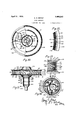
Fig. 10 is a plan view of the upper end of my improved device, partly broken away;
Fig. 11 is a side elevation of the head, partly broken away;
Fig. 12 is a detail of the heating element in the vessel, taken in horizontal section on the line 1212 of Fig. 11;
Fig. 13 is a cross-sectional detail of the same, partly broken away;
ig. 14 is a cross-sectional detail, taken in the plane of the line 14-14 of Fig. 2, to show the electric connections between the levyl brush-stands and the high brush-stands; an a Fig. 15 is a. side elevation of the head, partly broken away, and partly in central axial section, showing a modification.
My im roved device is intended to convert can y ingredients, which may, for instance, be ordinary granulated sugar. or other ingredients, into silk-like threads to produce so-called candy floss.
The ingredients are introduced into a vessel 21, the peripheral wall 22 of which is provided with openings 23, the vessel being provided with an electric heating element 24. The ingredients are placed in the vessel through an opening 25.
The vessel is rotated, and while being rotated heat is supplied to the ingredients by means of the heating element, whereby the ingredients adjacent to the heating element are caused to melt and to be projected by centrifugal force, due to the rotation of the vessel, through interstices in the heating element and openings in the periphery of the vessel, to produce the silk-like strands of the candy lloss.
Means are provided for independently regulating the heat of the heating element, and also for independently regulating the speeds of rotation of the. vessel, so that the heat as well as the speed of the heating element may be independently regulated throughout the course of producing the candy floss, in order to provide the necessary amount of heat and the necessary speed of rotation, as the condition of the candy floss being ejected may suggest.
The frame of the machine preferably comprises a base 31 on which there is a pedestal 32, releasably secured to the base by screws 34. The pedestal may comprise a releasable top 35, held to the pedestal proper by bolts 36 and nuts 37, 38. The pedestal preferably comprises the casing of an electric motor 41.
his motor is in upright position, its rotating armature 1:2 being in upright position and comprising an armature shaft 43 journaled in bearings 4-1, 45. The commutator 46 of the electric motor has suitable brushes 47 complemental thereto.
An insulating spool 51 is supported on the pedestal. preferably; in spaced relation thereto, for instance, y having stems 52 threaded into the upper end of the pedestal, as shown at 53, the insulating spool being supported on the tops of these stems and secured thereto by screws 54. The upright shaft extends upwardly through the bore 55 of the spool, and has an upward extension 56.
A head is secured to the upward extension of the shaft, preferably in readily releasable relation. This head comprises the vessel 21 and a downwardly extending por tion to which the vessel is secured, the downwardly extending portion being received over the upper end of the shaft and having )ortions of the electric connections for the eating element in the vessel thereon.
Thus the downward extension comprises a bushing 61. the lower end of which is provided with slots (32 to form fingers 63 frictionally contacting the shaft and frictionallv holding the head tothe shaft, and providing for ready upward removal of the head and ready attaching of the head about the shaft.
The upper end of this bushing. which may he of metal, is provided with an annular flange 64, forming an annular shoulder 65 at its top and an annular shoulder 66 at its bottom. End insulating sleeves 67, 68, and an intermediate insulating sleeve 69 are received about the bushing and preferably have annular spaces 71, 72, between them. The upper insulating sleeve is provided with an annular shoulder 75, the lower insulating sleeve is provided with an annular shoulder 76, and the intermediate insulating sleeve is rovided with an annular rib 77, forming annular shoulders respectively at. its top and at its bottom.
A pair of brush-stands 85 are provided with brushes 86, arranged to contact the contact-ring 80. A pair of brush-stands 87 are provided with brushes 89. arranged to contact the contact-ring 81. The brush-stands 85 are the longer of the brush-stands to coact with the upper contact-ring, and the brush-stands 87 are the shorter brush-stands to enact with the lower contact-ring.
The longer brush-stands 85 are secured to the insulating spool 51 by means of screws 91 and nuts 92, the screws and nuts also acting as binding posts. The shorter brushstands are secured to the insulating spool 51 by means of screws 93 and nuts 94, the screws and nuts also serving as binding posts.
The upper end of the bushing 61 is threaded, as shown at 96, and has a nut 97 received thereover, the nut arranged to contact the shoulder 65. The vessel 21 comprises an uper plate 101 and a lower plate 102. The ower plate is provided with a central depression 103, at the bottom of which there is an inwardly extending radial flange 104, arranged to rest upon the nut 97. A second nut 105 is threaded over the threaded end of the bushing and is arranged to clamp the flange 104 between said nuts and to center said lower plate about the bushing.
The upper plate is provided with the central opening 25, through which the charge of ingredients or sugar is arranged to be passed into the vessel. The upper plate is provided with an upwardly slanting central wall 109, at the upper end of which the opening 25 is located. this wall slanting downwardly and outwardly from the opening in order to lead the charge being supplied toward the periphery of the vessel, in case the centrifugal force of the rotating vessel acts upon the charge while being sup plied.
The upper plate and the lower plate are respectively provided with outwardlv extending annular bends 111, 112. to form annular rabbets 113, 114-, between said plates.
The peripheral wall 22 is formed by an annular peripheral plate located between the upper plate and the lower plate, preferably at the edges of the latter, this peripheral late being rovided with the openings 23, iown exten ing slantingly across said outer peripheral p ate. This peripheral plate is preferably rovided with inwardly radially extending anges 115, 116, respectively at the top and at the bottom of the peripheral late. These flanges and the u per and ower edges of the peripheral plate are located in the annular rabbets The peripheral plate is preferably provided with slanting edges 117, 118, at its top and bottom, referably located respectively above and elow said opening. Annular lips 119, 120, are preferably located at the outside of the peripheral plate at the top and at the bottom of the latter, shown formed by bending the peripheral edges of the upper plate and the lower plate respectively. This construction forms an annular mouth for the rotating vessel, which has a tendency to cause the candy floss to spread up and down as the same is eljected by centrifugal force from the vesse The eripheral plate and its flanges are preferably formed as an annular structure, the respective ends whereof are connected by providing a tongue 121 at one end of said structure received through openings 23 adjacent the other end of said structure, the end of said tongue being bent as a clip 122 upon the wall between said openings.
An annular heating element 24 is provided for the head, and is shown formed up out of a strip of electric resistance ma.- terial provided with a suitable insulating coating 128, and bent as a flat spiral structure to form downwardly slanting stretches 129 and upwardly slanting stretches 130, slanting with relation to each other and connected at their tops and bottoms by reverse bends in the strip. The res ective ends of the stripare respectively ocated in and positioned in spaced relation by a block 132 of insulating material. the ends of the strip extending toward the middle of the vessel as electric conductors 133, 134, where electric connection is made with the same.
The stretches of the heating element have narrow slots 135, 136, between them, which register at portions of their heights and form apertures through which the molten candy is projected, numbers of these apertures coinciding with the openings 23 in the peripheral plate. The heating element is flexible and 1s annularly received '.;at the inside of the peripheral plate, being preferably located in the peripheral plate structure. The centrifuge force acting upon the heating element during the rotation of the vessel causes the heating element to be urged toward said peripheral plate and to be held by said peripheral plate.
Electric current is supplied to the device from a suitable source of electric energy by means of the electric conductors 141, 142, releasably connecting with the electric connections 143, 144, by means of a suitable electric lug 145.
The e ectric conductor 143 is electrically connected with electric conductors 146, 147. The electric conductor 144 is electrically connected with electric conductors 148, 149. The electric conductor 146 is electrically connected with the electro-conductive arm 151 of an electric rheostat 152 secured in the base 31 of the machine, as by means of screws 153 passing through posts 154 into the upper wall of the base. This arm of the rheostat is provided with an insulatin handle 155, which passes outwardly throu a slot 156 in the front of the base of t e machine, The arm is provided with an electric contact 157 arrau ed to make electric contact with suitable uttons 158, suitably connected with the resistances 159 of the rheostat. The button 160 may be neutral.
The electric conductor 147 makes electric connection with the electroconductive arm 161 of an electric rheostat 162, suitably secured in the lower portion of the pedestal 32 of the machine, as by means of screws 163 threaded into the frame of the pedestal. The arm 161 is provided with an insulating handle 164 extending through a slot 165 III the front of the lower portion of the pedestal. The arm is provided with an electric contact 166 arranged to make electric contact with suitable buttons 167, with which suit-able resistances 168 of the rheostat makes connection. The button 169 may be neutral.
The rheostat 152 is exemplified as the rheostat for regulatin the heat of the-heating element, and the r eostat 162 is exemplified as the rheostat for regulating the s eeds of rotation of the electric motor. These rheostats are secured in superposed relation below the upright electric motor, so that preferably the rheostats, the electric motor and the head are arranged in superposed relation. 7
An electric conductor 171 connects with the rheostat 152 and with one terminal of an electric switch 172, an electric conductor 173 connecting the other terminaLof said electric switch with the binding posts 93, 94 of the shorter brush-stands 87,'a portion of said electric conductor connecting said shorter brush-stands with each other. The brushes 88 of said brush-stands electrically contact the contact-ring 81. An electric conductor 174 is electrically connected with said contact-ring (see Fig. 3), and passes through apertures in the intermediate insulating sleeve 69 and the upper insulating sleeve 67 and through an insulating bushing 175 in the flange (34 of the bushing 61. and through an aperture in an insulating block 177 received in an upper recess 178 in said bushing 61. The insulating block is secured to the bushing 61 by a screw 179. The electric conductor 174 is at its upper end electrically connected with a terminal post 180 in said block. The electric conductor 134, extending inwardly from one end of the heating element, is also electrically connected with said terminal post.
The other inwardly extending electric conductor 133, extending from the other end of said heating element, is electrically connected with a terminal post 181 in said insulating block 177, an electric conductor 182 also connecting with said terminal post and passing through an aperture in said insulating block, an insulating bushing 184 in the flange 64 of the bushing 61, and through an aperture in the upper insulating sleeve 67, being then connected with the upper contact-ring 80, (see Fig. 3). The brushes 86 of the longer brush-stands are arranged to make electric contact with said contact-ring. The lower ends of said brush-stands are electrically connected by means of the terminal posts 91, 92, with the electric conductor 148, a portion of which extends between said terminal posts.
An electric conductor 191 is connected at one end with the end one of the buttons of the rheostat 162, and at its other end with one of the brushes 47 of the electric motor. The other brush of said electric motor has electric connection with an electric conductor 192, which may have connection with a suitable binding post 193 of the rheostat 162, and lead thence as the electric conductor 149.
The handles 155, 164, of the rheostats 152, 162, are conveniently placed at the front of the machine in superposed relation, so that both the heat of the heating element and the speed of rotation of the head may be relatively regulated independent of each other, and, if desired, the electric current for the heating element may be instantly interrupted or connected by means of the switch 172, also conveniently placed adjacent to the front of the machine, so that, if desired, the heat of the heating element may be instantly cut off while the rotation of the head continues, or again connected, according to the requirements of trade for always providing a fresh supply of candy floss in the bowl and preventing burning of the candy; The ejection of the ingredients from the vessel by centriliidgal force takes place onlywhile said ingr cuts are in molten condition;
as the slots or interstices between the strands of the heating element are too narrow to permit the passage of the ingredients in unmolten state.
A bowl 196 surrounds the head and is arranged to receive the candy which is ejected by the head. An annular shelf 197 is provided at the top of the pedestal, being secured thereto by screws 198. The shelf is provided with an inner upwardly extending annular flange 199. A pad 200 is arranged to be received on the shelf. The bottom 201 of the bowl is provided with an opening 2112 at its middle, the bottom being upturned to form an annular flange 203 at said opening. The outer face of the flange 199 of the shelf is threaded and is arranged to have a nut 201 received thercovcr for contacting the flange 203 of the bowl and securely clamping the bowl between the shelf and its pad and said nut, and also centering the bowl upon the pedestal.
A shell 20? is l'cccivcd about the lowcr'extension of the head and the electric contacts thcrcat. It is provided with an inner annular insulating lining 208 and with an upper inwardly extending radial flange 299 for substantially closing the space about the lower portion of said head. The lower end of the shelf is received within the flange 199 and is connected therewith, as by means of bayonet slot and pin joints 210, an annular shoulder 211 of the shell contacting the upper end of the flange 199 for securely holding the shell in lace. The shell protects the parts enclose thereby from contact with the candy floss formed in the bowl, and insures proper electric conductivity of the electric contacts therein for the rotating electric heating element.
I have found that it is also desirable to eject the candy floss from the openings in the periphery of the head in substantially straight lines, and to counteract the 5 reading action up and down of the candy oss, as thereby a better control of the same is had within the bowl, especially when a shallow bowl is employed. \Vhen this is desired, I form the lips at the periphery of the head so as to extend in substantially parallel planes beyond the peripheral wall of the head in which the openings are located. and substantially perpendicular to the axis of rotation of the head, as more fully shown at 219, 220, in Fig. 15. I lind that the combination of a low wide-mouthed infeeding funnel. as shown by the upwardly slanting central frusto-conical wall 109, in connection with the substantially straight lips 219, 220, to control the ejection of the candy floss, produce a very superior candy floss of extremely neat and pure appearance, when ejected into the bowl, the arrangement being such as to control the ejection with the limits of a comparatively shallow bowl, so as to avoid the projection of the candy floss beyond the rim of the bowl.
Having thus fully described my invention, what 1 claim as new, and desire to secure by Letters Patent, is:
1. In a candy machine of the character de scribed, the combination of a rotatable head, an electric motor for rotating said head, a rotatable electric heating element at said head rotating with said head, electric connections from a source of electricity for said electric motor including a rheostat, electric connections from a source of electricity for said heating element including brushes and rota table electric contacts thm'el'or adjacent to said head, said last-named electric connections including a rheost at, and means for independently operating said rheostats for adj ustably controlling the speeds of rotation and the heat of said heating element with relation to each other and independent of each other, so as to provide various speeds of rotation for said head and said rotatable electric heatin element and various degrees of heat; for said rotatable electric heating element at each of the speeds of the latter.
2. In a candy machine of the character described, the combination of a frame comprising a base and a pedestal mounted thereon, an upright electric motor in said pedestal having a rotatable armature, an upright shaft operated thereby, a rotatable head at the upper end of said shaft above said pedestal, said rotatable head including a rotatable electric heating element, electric connections for said electrlc motor Including a rhoostat, electric connections for said electric heating element including a rheostat, means for supporting said rheostats respectively in said pedestal and said base in superposed relations under said electric motor, and means extending to outside said pedestal and said base respectively for independently operating said rheoslats for adjust-ably controllin the speeds of rotation and the heat of sai heating element with relation to each other and independent of each other, so as to provide various speeds of rotation for said head and said rotatable electric heating element and various degrees of heat for said rotatable electric heating element at each of the speeds of the latter.
3. In a candy machine of the character described, the combination of a pedestal, an upright electric motor mounted therein comprising an upright armature-shaft extending above said pedestal, an annular insulating sleeve-like support surrounding said shaft, means for supportin said support at the upper end of said pe estal, a rotatable head comprising a rotatable heating element and rotatable annular electric contacts, brushstands secured to said annular insulating support, brushes thereon for said rotatable annular electric contacts, and means securing said head to the upper end of said shaft.
4. In a candy machine of the character described, the combination of a-frame, an upright electric motor mounted therein, an upright shaft rotated by said motor and extending upwardl therefrom, an insulatin spool about said shaft supported by sai frame in spaced relation from said frame, a. rotatable head comprising a. rotatable vessel and an annular electric heating element therefor arranged to discharge candy floss by centrifugal force, said head comprising an insulating sleeve about said shaft under said vessel, a pair of electric contact-rings on said sleeve, brush-stands of difi'erent heights including brushes for said respective contact-rin means for securin the lower ends of said brush-stands to sai insulating spool, a bowl positioned on said frame about said contact-rings and said brush-stands to receive said candy floss, and a shell within said bowl protectingly received about said contact-rings and said brush-stands.
In testimony whereof, I have hereunto signed my name in the presence of two subscribing witnesses:
GEORGE E. BRENT. In presence of- PAUL V. CONNOLLY, DELMA Wnzmsmo.
Priority Applications (1)
| Application Number | Priority Date | Filing Date | Title |
|---|---|---|---|
| US564531A US1489342A (en) | 1922-05-29 | 1922-05-29 | Candy machine |
Applications Claiming Priority (1)
| Application Number | Priority Date | Filing Date | Title |
|---|---|---|---|
| US564531A US1489342A (en) | 1922-05-29 | 1922-05-29 | Candy machine |
Publications (1)
| Publication Number | Publication Date |
|---|---|
| US1489342A true US1489342A (en) | 1924-04-08 |
Family
ID=24254851
Family Applications (1)
| Application Number | Title | Priority Date | Filing Date |
|---|---|---|---|
| US564531A Expired - Lifetime US1489342A (en) | 1922-05-29 | 1922-05-29 | Candy machine |
Country Status (1)
| Country | Link |
|---|---|
| US (1) | US1489342A (en) |
Cited By (34)
| Publication number | Priority date | Publication date | Assignee | Title |
|---|---|---|---|---|
| US3036532A (en) * | 1960-06-28 | 1962-05-29 | Bowe John | Cotton candy machine with product of alternating colors |
| US3125967A (en) * | 1964-03-24 | Controls for candy cotton machine | ||
| US3221675A (en) * | 1962-03-07 | 1965-12-07 | Pillsbury Co | Method of manufacturing a food product |
| US3232244A (en) * | 1962-03-29 | 1966-02-01 | Link Res And Dev Corp | Cotton candy machine |
| US4501538A (en) * | 1982-06-17 | 1985-02-26 | Bray Carl R | Cotton candy accessory for blender |
| US4793782A (en) * | 1986-12-17 | 1988-12-27 | Sells-Floto Inc. | Cotton candy machine |
| FR2700556A1 (en) * | 1993-01-20 | 1994-07-22 | Freudenberg Carl | Apparatus for manufacturing filaments from a fusible material. |
| US5346377A (en) * | 1993-10-07 | 1994-09-13 | Fuisz Technologies Ltd. | Apparatus for flash flow processing having feed rate control |
| US5441754A (en) * | 1993-11-12 | 1995-08-15 | Gold Medal Products Co. | High volume single color cotton candy machine |
| US5445769A (en) * | 1994-06-27 | 1995-08-29 | Fuisz Technologies Ltd. | Spinner head for flash flow processing |
| US5447423A (en) * | 1993-03-30 | 1995-09-05 | Fuisz Technologies, Ltd. | Apparatus for transforming the physical structure of thermo-flow materials |
| US5458823A (en) * | 1994-10-28 | 1995-10-17 | Fuisz Technologies Ltd. | Method and apparatus for spinning feedstock material |
| US5498144A (en) * | 1994-04-07 | 1996-03-12 | Gold Medal Products Co. | Cotton candy machine and sugar controller |
| US5511961A (en) * | 1994-06-30 | 1996-04-30 | Sullivan; John T. | Machine for manufacturing cotton candy balls |
| US5549917A (en) * | 1994-07-01 | 1996-08-27 | Fuisz Technologies Ltd. | Flash flow formed solloid delivery systems |
| US5556652A (en) * | 1994-08-05 | 1996-09-17 | Fuisz Technologies Ltd. | Comestibles containing stabilized highly odorous flavor component delivery systems |
| US5576042A (en) * | 1991-10-25 | 1996-11-19 | Fuisz Technologies Ltd. | High intensity particulate polysaccharide based liquids |
| US5587198A (en) * | 1995-05-31 | 1996-12-24 | Fuisz Technologies Ltd. | Positive hydration method of preparing confectionery and product therefrom |
| US5597608A (en) * | 1991-10-25 | 1997-01-28 | Fuisz Technologies Ltd. | Saccharide-based matrix incorporating maltodextrin and process for making |
| US5728397A (en) * | 1992-05-12 | 1998-03-17 | Fuisz Technologies Ltd. | Polydextrose product and process |
| US5779946A (en) * | 1993-04-19 | 1998-07-14 | Fuisz Technologies Ltd. | Method for spin processing material having temperature feedback control |
| US5811123A (en) * | 1991-12-17 | 1998-09-22 | Fuisz Technologies Ltd. | Method of treating mucosal tissue |
| US5851454A (en) * | 1997-06-13 | 1998-12-22 | Fuisz Technologies, Ltd. | Spinner head having flow restricting inserts |
| US5939120A (en) * | 1997-11-07 | 1999-08-17 | Fuisz Technologies Ltd. | Externally heated material processing apparatus and method |
| US6284164B1 (en) * | 1997-04-18 | 2001-09-04 | Gold Medal Products Company | Cotton candy machine |
| US6585504B2 (en) | 2000-11-30 | 2003-07-01 | Gold Medal Products Company, Inc. | Cotton candy apparatus utilizing spinner head with film heater |
| US6752071B1 (en) | 2002-02-15 | 2004-06-22 | Gold Medal Products Company | Thick film heater for a popcorn popper |
| US20040185131A1 (en) * | 2003-03-18 | 2004-09-23 | Gold Medal Products Company | Cotton candy machine with tubular heater |
| US20050136112A1 (en) * | 2003-12-19 | 2005-06-23 | Pediamed Pharmaceuticals, Inc. | Oral medicament delivery system |
| US20050238774A1 (en) * | 2004-04-22 | 2005-10-27 | Gold Medal Products Co. | Cotton candy machine |
| US20070278706A1 (en) * | 2006-05-30 | 2007-12-06 | C. Cretors And Company | Cotton candy handling device |
| US20080171098A1 (en) * | 2007-01-12 | 2008-07-17 | Gold Medal Products Company | Locking System For A Cotton Candy Machine |
| US8376064B1 (en) | 2009-01-21 | 2013-02-19 | David Swegle | Quick release head assembly on cotton candy machine |
| US10244773B2 (en) * | 2015-07-01 | 2019-04-02 | Agatsuma Co., Ltd | Cotton candy preparing device |
-
1922
- 1922-05-29 US US564531A patent/US1489342A/en not_active Expired - Lifetime
Cited By (45)
| Publication number | Priority date | Publication date | Assignee | Title |
|---|---|---|---|---|
| US3125967A (en) * | 1964-03-24 | Controls for candy cotton machine | ||
| US3036532A (en) * | 1960-06-28 | 1962-05-29 | Bowe John | Cotton candy machine with product of alternating colors |
| US3221675A (en) * | 1962-03-07 | 1965-12-07 | Pillsbury Co | Method of manufacturing a food product |
| US3232244A (en) * | 1962-03-29 | 1966-02-01 | Link Res And Dev Corp | Cotton candy machine |
| US4501538A (en) * | 1982-06-17 | 1985-02-26 | Bray Carl R | Cotton candy accessory for blender |
| US4793782A (en) * | 1986-12-17 | 1988-12-27 | Sells-Floto Inc. | Cotton candy machine |
| US5709876A (en) * | 1991-10-25 | 1998-01-20 | Fuisz Technologies Ltd. | Saccharide-based matrix |
| US5597608A (en) * | 1991-10-25 | 1997-01-28 | Fuisz Technologies Ltd. | Saccharide-based matrix incorporating maltodextrin and process for making |
| US5576042A (en) * | 1991-10-25 | 1996-11-19 | Fuisz Technologies Ltd. | High intensity particulate polysaccharide based liquids |
| US5811123A (en) * | 1991-12-17 | 1998-09-22 | Fuisz Technologies Ltd. | Method of treating mucosal tissue |
| US5728397A (en) * | 1992-05-12 | 1998-03-17 | Fuisz Technologies Ltd. | Polydextrose product and process |
| FR2700556A1 (en) * | 1993-01-20 | 1994-07-22 | Freudenberg Carl | Apparatus for manufacturing filaments from a fusible material. |
| US5447423A (en) * | 1993-03-30 | 1995-09-05 | Fuisz Technologies, Ltd. | Apparatus for transforming the physical structure of thermo-flow materials |
| US5779946A (en) * | 1993-04-19 | 1998-07-14 | Fuisz Technologies Ltd. | Method for spin processing material having temperature feedback control |
| US5520859A (en) * | 1993-10-07 | 1996-05-28 | Fuisz Technologies Ltd. | Method for flash flow processing having feed rate control |
| US5346377A (en) * | 1993-10-07 | 1994-09-13 | Fuisz Technologies Ltd. | Apparatus for flash flow processing having feed rate control |
| US5441754A (en) * | 1993-11-12 | 1995-08-15 | Gold Medal Products Co. | High volume single color cotton candy machine |
| US5498144A (en) * | 1994-04-07 | 1996-03-12 | Gold Medal Products Co. | Cotton candy machine and sugar controller |
| US5445769A (en) * | 1994-06-27 | 1995-08-29 | Fuisz Technologies Ltd. | Spinner head for flash flow processing |
| US5511961A (en) * | 1994-06-30 | 1996-04-30 | Sullivan; John T. | Machine for manufacturing cotton candy balls |
| US5549917A (en) * | 1994-07-01 | 1996-08-27 | Fuisz Technologies Ltd. | Flash flow formed solloid delivery systems |
| US5824342A (en) * | 1994-07-01 | 1998-10-20 | Fuisz Technologies Ltd. | Flash flow formed solloid delivery systems |
| US5582855A (en) * | 1994-07-01 | 1996-12-10 | Fuisz Technologies Ltd. | Flash flow formed solloid delivery systems |
| US5556652A (en) * | 1994-08-05 | 1996-09-17 | Fuisz Technologies Ltd. | Comestibles containing stabilized highly odorous flavor component delivery systems |
| US5633027A (en) * | 1994-08-05 | 1997-05-27 | Fuisz Technologies Ltd. | Confectioneries containing stabilized highly odorous flavor component delivery systems |
| US5744180A (en) * | 1994-08-05 | 1998-04-28 | Fuisz Technologies Ltd. | Comestibles containing stabilized highly odorous flavor component delivery systems |
| US5458823A (en) * | 1994-10-28 | 1995-10-17 | Fuisz Technologies Ltd. | Method and apparatus for spinning feedstock material |
| EP0709035A2 (en) | 1994-10-28 | 1996-05-01 | Fuisz Technologies Ltd. | Method and apparatus for spinning meltable material |
| US5804247A (en) * | 1995-05-31 | 1998-09-08 | Fuisz Technologies Ltd. | Positive hydration method of preparing confectionary and product therefrom |
| US5587198A (en) * | 1995-05-31 | 1996-12-24 | Fuisz Technologies Ltd. | Positive hydration method of preparing confectionery and product therefrom |
| US6284164B1 (en) * | 1997-04-18 | 2001-09-04 | Gold Medal Products Company | Cotton candy machine |
| US5851454A (en) * | 1997-06-13 | 1998-12-22 | Fuisz Technologies, Ltd. | Spinner head having flow restricting inserts |
| US5939120A (en) * | 1997-11-07 | 1999-08-17 | Fuisz Technologies Ltd. | Externally heated material processing apparatus and method |
| US6585504B2 (en) | 2000-11-30 | 2003-07-01 | Gold Medal Products Company, Inc. | Cotton candy apparatus utilizing spinner head with film heater |
| US6752071B1 (en) | 2002-02-15 | 2004-06-22 | Gold Medal Products Company | Thick film heater for a popcorn popper |
| US20040185131A1 (en) * | 2003-03-18 | 2004-09-23 | Gold Medal Products Company | Cotton candy machine with tubular heater |
| US20050136112A1 (en) * | 2003-12-19 | 2005-06-23 | Pediamed Pharmaceuticals, Inc. | Oral medicament delivery system |
| US20050238774A1 (en) * | 2004-04-22 | 2005-10-27 | Gold Medal Products Co. | Cotton candy machine |
| US20070278706A1 (en) * | 2006-05-30 | 2007-12-06 | C. Cretors And Company | Cotton candy handling device |
| US7641460B2 (en) * | 2006-05-30 | 2010-01-05 | C. Cretors & Company | Cotton candy handling device |
| US20080171098A1 (en) * | 2007-01-12 | 2008-07-17 | Gold Medal Products Company | Locking System For A Cotton Candy Machine |
| US7479002B2 (en) * | 2007-01-12 | 2009-01-20 | Gold Medal Products Company | Locking system for a cotton candy machine |
| US8376064B1 (en) | 2009-01-21 | 2013-02-19 | David Swegle | Quick release head assembly on cotton candy machine |
| US9808024B1 (en) * | 2009-01-21 | 2017-11-07 | David Swegle | Quick release head assembly on cotton candy machine |
| US10244773B2 (en) * | 2015-07-01 | 2019-04-02 | Agatsuma Co., Ltd | Cotton candy preparing device |
Similar Documents
| Publication | Publication Date | Title |
|---|---|---|
| US1489342A (en) | Candy machine | |
| US3036532A (en) | Cotton candy machine with product of alternating colors | |
| US3118396A (en) | Machine for making candy | |
| US1541378A (en) | Confection apparatus | |
| US3118397A (en) | Candy making machine | |
| US816055A (en) | Centrifugal melting device. | |
| US847366A (en) | Candy-spinning machine. | |
| JP2002360175A (en) | Apparatus for manufacturing cotton candy using spring- energized brush | |
| US1806111A (en) | Candy cotton forming machine | |
| US533445A (en) | denison | |
| US3141429A (en) | Sewing machine with built-in electric speed-responsive regulating systems | |
| US856424A (en) | Controlling an electric candy-spinning machine. | |
| US1738908A (en) | Electric melting pot | |
| US1573944A (en) | Switch control for electric hair driers | |
| US1282330A (en) | System of electric heating. | |
| US1454151A (en) | Electric hair drier | |
| US1378474A (en) | Sand-bath | |
| US1510940A (en) | Candy machine | |
| CN210954683U (en) | Gear adjusting circuit, frame and cooking machine | |
| US2247707A (en) | Kitchen utility device | |
| US1597241A (en) | Electric cooking utensil | |
| US1479494A (en) | Combined electric fan and heater | |
| US717756A (en) | Candy-machine. | |
| US3374758A (en) | Silicon controlled rectifier circuit arrangement for sewing machine drives | |
| US1563453A (en) | Electric heater |