US1464076A - Depositing metal by the electric arc - Google Patents
Depositing metal by the electric arc Download PDFInfo
- Publication number
- US1464076A US1464076A US193943A US19394317A US1464076A US 1464076 A US1464076 A US 1464076A US 193943 A US193943 A US 193943A US 19394317 A US19394317 A US 19394317A US 1464076 A US1464076 A US 1464076A
- Authority
- US
- United States
- Prior art keywords
- metal
- electric arc
- electrode
- tool
- mould
- Prior art date
- Legal status (The legal status is an assumption and is not a legal conclusion. Google has not performed a legal analysis and makes no representation as to the accuracy of the status listed.)
- Expired - Lifetime
Links
Images
Classifications
-
- B—PERFORMING OPERATIONS; TRANSPORTING
- B23—MACHINE TOOLS; METAL-WORKING NOT OTHERWISE PROVIDED FOR
- B23K—SOLDERING OR UNSOLDERING; WELDING; CLADDING OR PLATING BY SOLDERING OR WELDING; CUTTING BY APPLYING HEAT LOCALLY, e.g. FLAME CUTTING; WORKING BY LASER BEAM
- B23K9/00—Arc welding or cutting
- B23K9/02—Seam welding; Backing means; Inserts
- B23K9/038—Seam welding; Backing means; Inserts using moulding means
Definitions
- My invention has reference to the known method of depositing metal by the electric arc, and has for its objects improvements whereby the metal may be deposited without undue loss and whereby the deposited metal may be rendered free from blow holes or the like.
- the body of the tool may be formed of mild steel and thepart usually occupied by and adjacent to the cutting edge is or may be removed to leave room for the electric deposition of high speed steel and after sufiicient metal has been deposited,- the added metal is subto subsequent heating to remove blow oles therefrom.
- the deposited steel maybe caused to heap up without undue 1cm
- the tool or the cutting end thereof is placed in a mould or a mould is built up around the same to confine the fused metal, the mould being formed of. suitable refractory materials.
- the mould has to be constructed of carefully selected material, as an acid material (i. e. a material in which silica forms a fairly high proportion) is in some cases unsuitable as the silica is decomposed under heat of the electric arc and silicon is reduced and alloys with the molten steel.
- an acid material i. e. a material in which silica forms a fairly high proportion
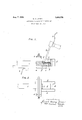
- Fig. 1 is a sectional elevation showing a machine tool with a part of the high speed steel electrically deposited on the cutting end.
- Fig. 2 is a plan showing a convenient type of mould for use in the rocess.
- a is a suitable metal bed electrically com the following is a nested at b with one pole of the source of.
- a is a tool body of mild d'leel or the like, the cutting end of which is arranged in a mould d suitably clamped to the tool such as by a clamp e.
- the metal electrode h is composed of all the materials necessary for depositing high speed steel, and is held in a suitable insulated handle, The electric current is caused to are across the space between the lower end of the electrode h and the metal 9 and in so doing fuses the metal of the electrode and do its same until the added-metal reaches a tiiiflmess approximately indicated by the dotted line It.
- the metal 9 is then kept in a state of fusion b a carbon electrode substituted for the e ectrode h or by a suitable blowpipe for a sufficient time to allow the fluid metal to settle and permit the gases therein to esca e.
- the mould d is of a sufiicient- Width to allow the metal 9 to project slightly beyond the width of the tool 0, so that when the metal 9 has sufficiently cooled down the metal 9 may be ground to the desired shape of cutting edge.
- any of the foregoing materials may be formed into moulds of the required shape by any well known method, I have found that very satisfactory moulds for this work can be made by using the spent material resulting from the manufacture of acetylene gas from calcium carbide, which material is at present a waste product, With this material I mix, for ex-' ample, a proportion (say 5 to 10%) of sodium silicate which by the well known ac tion of silica .upon lime, causes it to Set hard, and it is found that the proportion of sodium silicate required is not sufficient to alter the basic properties of the material.
- a proportion say 5 to 10%
- moulds for any subjected to subsequent heating by an electric arc, with. for example a carbon electrode, or by an oxyacetylene gas flame.
- an electric arc with. for example a carbon electrode, or by an oxyacetylene gas flame.
- the materials necessary for electrically depositing high sgeed steel are combined n one electrode an covered with slag forming material preferably asbestos yarn, so that under the influence of the electric arc high speed steel of any required variety or character may be deposited.
- the electrode may consist of channel section mild steel within which the mixture is located.
- a very satisfactor mixture contains the following ingre ients: carbon 1.30% tungsten 22% chromium 9%, vanadium 25%.
- the proportions of the different rare metals may be varied very considerably, for instance, many high speed. steels do, not contain more than about 6% of tungsten. Molybdenum may be used in place of a part of the tungsten, but it does not seem to show any advantage over tungsten. V
Landscapes
- Engineering & Computer Science (AREA)
- Physics & Mathematics (AREA)
- Plasma & Fusion (AREA)
- Mechanical Engineering (AREA)
- Silicon Compounds (AREA)
Description
Aug. 7, 1923.
. E. H. JONES DEPOSITING METAL BY THE ELECTRIC ARC Filed Sent. 29,. 1917 F'IG.I.
I I, mu
i c I l 6 K a i f ATTy.
Patented Aug. 7, 1923.-
UNITED STATES ERNEST JOKES, OI!- CANONBURY, LONDON, ENGLAND.
DEPOBITING METAL BY THE ELECTRIC ABC,
Application filed September .29, 1917. Serlal No. 198,943.
To all whom it may concern:
Be it known that I, Emvns'r HENRY J onus, subject of the. King of Great Britain, residing at 4 Grange Road, Canonbury, London, N, England, engineer, have invented new and useful Improvements in Depositing Metal by the Electric Are (for which I have filed ap lications in England Sept. 20, 1916, Patent $70. 109,321, A ril 12, 1917, Patent No. 109,652), of whic specification.
My invention has reference to the known method of depositing metal by the electric arc, and has for its objects improvements whereby the metal may be deposited without undue loss and whereby the deposited metal may be rendered free from blow holes or the like.
According to my invention, as applied to machine tools by way of example, the body of the tool may be formed of mild steel and thepart usually occupied by and adjacent to the cutting edge is or may be removed to leave room for the electric deposition of high speed steel and after sufiicient metal has been deposited,- the added metal is subto subsequent heating to remove blow oles therefrom. In order that the deposited steel maybe caused to heap up without undue 1cm, the tool or the cutting end thereof is placed in a mould or a mould is built up around the same to confine the fused metal, the mould being formed of. suitable refractory materials.
I have found that the mould has to be constructed of carefully selected material, as an acid material (i. e. a material in which silica forms a fairly high proportion) is in some cases unsuitable as the silica is decomposed under heat of the electric arc and silicon is reduced and alloys with the molten steel. I
The invention is illustrated by the accompanying drawings in which Fig. 1 is a sectional elevation showing a machine tool with a part of the high speed steel electrically deposited on the cutting end. Fig. 2 is a plan showing a convenient type of mould for use in the rocess.
a is a suitable metal bed electrically com the following is a nested at b with one pole of the source of.
electric current. a is a tool body of mild d'leel or the like, the cutting end of which is arranged in a mould d suitably clamped to the tool such as by a clamp e. The end of the tool body, which had previously been shaped with a cut-away part f, is shown with a portion of the requisite high speed steel 9' electrically deposited from themetal electrode h which is'connected at i to the other pole of the current. The metal electrode h is composed of all the materials necessary for depositing high speed steel, and is held in a suitable insulated handle, The electric current is caused to are across the space between the lower end of the electrode h and the metal 9 and in so doing fuses the metal of the electrode and do its same until the added-metal reaches a tiiiflmess approximately indicated by the dotted line It.
The metal 9 is then kept in a state of fusion b a carbon electrode substituted for the e ectrode h or by a suitable blowpipe for a sufficient time to allow the fluid metal to settle and permit the gases therein to esca e.
referably, the mould d is of a sufiicient- Width to allow the metal 9 to project slightly beyond the width of the tool 0, so that when the metal 9 has sufficiently cooled down the metal 9 may be ground to the desired shape of cutting edge.
In some cases it is desirable to use a mould of. basic material such as lime, dolomite, or magnetite for example and in constructing the mould any of the foregoing materials may be formed into moulds of the required shape by any well known method, I have found that very satisfactory moulds for this work can be made by using the spent material resulting from the manufacture of acetylene gas from calcium carbide, which material is at present a waste product, With this material I mix, for ex-' ample, a proportion (say 5 to 10%) of sodium silicate which by the well known ac tion of silica .upon lime, causes it to Set hard, and it is found that the proportion of sodium silicate required is not sufficient to alter the basic properties of the material.
v Another way of making moulds for any subjected to subsequent heating by an electric arc, with. for example a carbon electrode, or by an oxyacetylene gas flame. By this means the deposited metal subsides into a homogeneous mass free from blow holes or flaws, probably caused by occluded gas.
The materials necessary for electrically depositing high sgeed steel are combined n one electrode an covered with slag forming material preferably asbestos yarn, so that under the influence of the electric arc high speed steel of any required variety or character may be deposited.
For this purpose the electrode may consist of channel section mild steel within which the mixture is located. A very satisfactor mixture contains the following ingre ients: carbon 1.30% tungsten 22% chromium 9%, vanadium 25%.
The proportions of the different rare metals may be varied very considerably, for instance, many high speed. steels do, not contain more than about 6% of tungsten. Molybdenum may be used in place of a part of the tungsten, but it does not seem to show any advantage over tungsten. V
It will be understood that although I have described my invention as applied to depositing and settling high speed steel on machine tools, the invention is equally applicable to other alloys or metals and to other parts of machinery and other articles where a homogeneous deposit of metal is required, as for example a bearing surface or other surface or point where it is desirable tic resist undue wear or to make good a deect.
Having now particularly described and ascertained the nature of my said invention and in what manner the same is to be performed, I declare that what I claim is The process of applyin a high speed steel cutting ed to a tool, w ich consists in securing sai tool within an enclosing mould, the tool being electrically connected with one pole of a source of current, applying to said tool one end of an electrode containing the materials necessary to produce when fused a metal of the character required, said electrode being electrically connected with the other pole of the source of current, holding said electrode in contact with said tool until a sufiicient quantity of the electrode has been fused, then substituting a carbon electrode for said metal electrode and continuing the passage of the current while the tool remains in the mould until the deposited metal subsides into a homogeneous mass free from blowholes.
In testimony whereof I have signed my ERNEST HENRY JONES.
Witness ARTHUR U. DOWNING.
Priority Applications (1)
| Application Number | Priority Date | Filing Date | Title |
|---|---|---|---|
| US193943A US1464076A (en) | 1917-09-29 | 1917-09-29 | Depositing metal by the electric arc |
Applications Claiming Priority (1)
| Application Number | Priority Date | Filing Date | Title |
|---|---|---|---|
| US193943A US1464076A (en) | 1917-09-29 | 1917-09-29 | Depositing metal by the electric arc |
Publications (1)
| Publication Number | Publication Date |
|---|---|
| US1464076A true US1464076A (en) | 1923-08-07 |
Family
ID=22715668
Family Applications (1)
| Application Number | Title | Priority Date | Filing Date |
|---|---|---|---|
| US193943A Expired - Lifetime US1464076A (en) | 1917-09-29 | 1917-09-29 | Depositing metal by the electric arc |
Country Status (1)
| Country | Link |
|---|---|
| US (1) | US1464076A (en) |
Cited By (5)
| Publication number | Priority date | Publication date | Assignee | Title |
|---|---|---|---|---|
| US2550743A (en) * | 1948-10-01 | 1951-05-01 | American Steel Foundries | Method of welding brake beams |
| US2797304A (en) * | 1953-11-06 | 1957-06-25 | Gen Electric Co Ltd | Methods of welding |
| US2867137A (en) * | 1954-11-09 | 1959-01-06 | Wilbur R Joy | Cutting tools and method of making same |
| US3060123A (en) * | 1952-12-17 | 1962-10-23 | Bell Telephone Labor Inc | Method of processing semiconductive materials |
| US3905283A (en) * | 1974-05-08 | 1975-09-16 | Rockwell International Corp | Improved rotary cutting die |
-
1917
- 1917-09-29 US US193943A patent/US1464076A/en not_active Expired - Lifetime
Cited By (5)
| Publication number | Priority date | Publication date | Assignee | Title |
|---|---|---|---|---|
| US2550743A (en) * | 1948-10-01 | 1951-05-01 | American Steel Foundries | Method of welding brake beams |
| US3060123A (en) * | 1952-12-17 | 1962-10-23 | Bell Telephone Labor Inc | Method of processing semiconductive materials |
| US2797304A (en) * | 1953-11-06 | 1957-06-25 | Gen Electric Co Ltd | Methods of welding |
| US2867137A (en) * | 1954-11-09 | 1959-01-06 | Wilbur R Joy | Cutting tools and method of making same |
| US3905283A (en) * | 1974-05-08 | 1975-09-16 | Rockwell International Corp | Improved rotary cutting die |
Similar Documents
| Publication | Publication Date | Title |
|---|---|---|
| US2043960A (en) | Electric welding | |
| US2191469A (en) | Veneering of metallic surfaces | |
| US2694023A (en) | Metal treating flux | |
| US1746207A (en) | Method and apparatus for electric arc welding | |
| US1464076A (en) | Depositing metal by the electric arc | |
| US2003167A (en) | Apparatus for fusing powdered materials | |
| US3582604A (en) | Method of plasma treatment of metals | |
| US1901654A (en) | Cutting tool and process of making it | |
| US1757601A (en) | Welding rod | |
| US4048348A (en) | Method of applying a fused silica coating to a substrate | |
| US2002198A (en) | Surface hardening metal articles | |
| US2390805A (en) | Method of making metallic articles | |
| US3062948A (en) | Method of forming hard surfacing | |
| US2194200A (en) | Electrical welding flux and method | |
| US1708815A (en) | Process of welding cast iron and filler rod therefor | |
| US2807562A (en) | Welding composition for hard facing | |
| US1933343A (en) | Electrode | |
| US2210314A (en) | Method for attaching hard alloys | |
| US2184518A (en) | Welding rod and hard overlay deposited therefrom | |
| US1840921A (en) | Bronze for welding | |
| US3042790A (en) | Process of electric arc welding, machine and weld insert | |
| US1327267A (en) | Process of welding | |
| US1958649A (en) | Arc welding | |
| US2041343A (en) | Method of changing the grain structure of metals | |
| US3196538A (en) | Hard-surfacing process |