US1413235A - Liquid-level gauge - Google Patents
Liquid-level gauge Download PDFInfo
- Publication number
- US1413235A US1413235A US433627A US43362720A US1413235A US 1413235 A US1413235 A US 1413235A US 433627 A US433627 A US 433627A US 43362720 A US43362720 A US 43362720A US 1413235 A US1413235 A US 1413235A
- Authority
- US
- United States
- Prior art keywords
- liquid
- pipe
- chambers
- chamber
- diaphragm
- Prior art date
- Legal status (The legal status is an assumption and is not a legal conclusion. Google has not performed a legal analysis and makes no representation as to the accuracy of the status listed.)
- Expired - Lifetime
Links
Images
Classifications
-
- G—PHYSICS
- G01—MEASURING; TESTING
- G01F—MEASURING VOLUME, VOLUME FLOW, MASS FLOW OR LIQUID LEVEL; METERING BY VOLUME
- G01F23/00—Indicating or measuring liquid level or level of fluent solid material, e.g. indicating in terms of volume or indicating by means of an alarm
- G01F23/14—Indicating or measuring liquid level or level of fluent solid material, e.g. indicating in terms of volume or indicating by means of an alarm by measurement of pressure
- G01F23/16—Indicating, recording, or alarm devices being actuated by mechanical or fluid means, e.g. using gas, mercury, or a diaphragm as transmitting element, or by a column of liquid
- G01F23/164—Indicating, recording, or alarm devices being actuated by mechanical or fluid means, e.g. using gas, mercury, or a diaphragm as transmitting element, or by a column of liquid using a diaphragm, bellow as transmitting element
Definitions
- This .invention relates to li uid level gauges and particularly to that c ass thereof which is adapted for indicating, preferably on a scale, the height of a body of liquid in a tank remote from the scale and located at any height relatively to said scale.
- the object of our im rovements is to provide a gauge of the c ass specified, simple in construction, accurate in operation, and which ma be used with equal facility in a number 0 different environments.
- 2 is a tank, such for instance as is adapted for holdin the gasoline supply in an automobile.
- his tank may be rovided with the usual supply pipe 21 leading to the engine, not shown. It is also provided with a pipe 3, preferably leading from the bottom of the tank and communicating with the upper face of diaphragm 7, in diaphragm box 5.
- This ipe 3 may be conveniently enlarged at its ower end to form a receiving 7 chamber 4 in the upper part of box 5.
- Said box is divided through its mid-portion by rigid wall 6, and spaced apart therein above and below said rigid wall are diaphragms 7 and 8 respectively, whereby are formed chambers 9,and 10.
- diaphragm 8 may be exposed to the atmosphere, or said diaphragm may form the upper wall of an expansion chamber 22 containing air, and which chamber may be closed by a plug, not shown, in outlet 23, to keep said diaphragm free of dirt.
- the terms upper and ower as applied to chambers 9 and 10 are relative only, as said box 5 may with equal efficiency be placed on its side with diaphragms 7 and 8 in vertical positions, or said box may be arranged in any other convenient position.
- chamber 9 Connected with chamber 9 is one end of pipe 11, of small calibre, and which pipe leads from said chamber to some convenient place of observation, preferably to gauge glass 19 inserted in said pipe at scale 12, conveniently located for reading, as for instance on the instrument board of the automobile, not shown, in which automobile the gasoline tank is installed.
- Said pipe 11 after passing said scale makes a return bend at 13 and the other end, 14, of said pipe is connected with chamber 10 of the diaphragm box. That portion of pipe 11 comprised of gauge glass 19 being transparent the contents of said pipe are visible therethrough. ⁇ Vhile it would be theoretically acceptable to have the whole of pipe 11 of glass, it is obvious that all but that ortion adjacent the scale is preferably mad of metal so as to withstand bendin and shocks incident to a moving vehicle.
- hambers 9 and 10 may be provided with openings 15 and 16 respectively, closed by plugs as shown, for the purpose of filling the gauge system with an indicating fluid, such as colored alcohol.
- Chambers 9 and 10 and pipe 11 are filled with such fluid except for a short space opposite the scale, and which space is occu led by indicating means such as a bubble of air 17.
- the filling of pipe 11 .and the proper location of the air bubble may be accomplished with the assistance of vent cook 18 at the top of the gauge glass 19.
- Diaphragms 7 and 8 are for convenience usually made of equal diameter, thickness and resilience, and chambers 9 and 10 of equal capacity, but variations in these regards may be made with equally efiicient results, the
- tank 2 is illustrated as about half filled and bubble 17 is shown at a proportionate height against scale 12.
- the weight of the column on top of diaphragm 7 is correspondingly decreased, thus permitting said diaphragm to move upwardly, whereby the size of chamber 9 is increased and a small portion of the liquid from ipe 11 flows thereinto, thereby lowering bu ble 17 a proportionate amount, and a small portion of the liquid in chamber 10 flows outwardly into return pipe 14 and thence into gau glass 19 following bubble 17 downwar ly.
- a gau e for fluids the combination of a tank for t e liquid to be gauged, a diaphra 111 box below said tank inc uding two cham rs separated by a rigid wall, each of said chambers having a yieldable diaphra forming one wall thereof, a communicating passage from said tank to the outer face of one of said diaphragms, a ipe leading from one of said chambers an back to the other chamber, and a transparent ortion in said ipe, said chambers and said pipe being fifled with a liquid except for the resence of a bubble of air therein, and said bubble of air being located within the transparent portion of said dpipe. 55 2.
- a gauge for flui the combination of a tank for the liquid to be gauged, :1 diaphragm box below said tank including two chambers separated by a rigid wall, each of said chambers having a yieldable diaphragm forming one wall thereof, a communicating passage from said tank to the outer face of one 0 said diaphragms, a scale, a pipe leading from one of said chambers to said scale and back to the other chamber, and a trans 65 parent portion in said pipe opposite said scale.
- said chambers and said pipe being filled with a liquid except for the presence of a bubble of air thereln, and said bubble of air being located within the transparent portion of said pipe.
- a diaphragm box below said tank including two chambers separated by a rigid wall, each of said chambers havin a yieldable diaphragm forming one wafi thereof, a chamber above one of said diaphragms the lower wall of which is formed by said diaphragm, a chamber below the other diaphragm the upper wall of which is formed y said other dialphragm, means for permitting access of t e liquid to be gauged to the outer face of the diaphragm of one of the two chambers separated by the rigid wall, a pipe leading from one of the chambers separated by said rigid wall to the other thereof, a transparent portion in said pipe, said pipe being filled with a liquid except for the resence of a bubble of air therein, and sai bubble of air being located within the transparent portion of said pipe.
- a diaphragm box including two chambers separated by a rigid wall, each of said chambers having a yieldable diaphragm forming one wall thereof, a pipe leading from one of said chambers and back to the other chamber, a transparent portion in said pipe, said pipe being filled with a liquid except for the resence of a bubble of air therein, 100 said bub le of air being located within the transparent portion of said ipe, and means for permitting access of t e liquid to be gauged to the outer face of the diaphra m of one of the two chambers separated y 105 the rigid wall.
- a liquid level gauge the combination of a box including two chambers separated by a rigid wall, each of said chambers having a yieldable 'wall, a pipe containing 110 liquid and leading from one of said chambers back to the other chamber, a transparent portion in said pipe, means in the iquid in said pipe located within the transparent portion thereof for indicating the 11 eight of the liquid to be gauged, and means for permitting access of the liquid to be gen (1 to the outer face of the yieldable wal of one of said two chambers.
- a liquid level auge the combination 120 of two chambers, eac having a yieldable wall, a pipe containing fluid leading from one of sai chambers back to the other chamber, a transparent portion in said pipe, means in the fluid in said pi located with- 125 in the transparent portion t ereof for indicating the height of the liquid to be gauged, and means for permitting access of the liquid to be aged to the outer face of the yieldable we I of one of said two chambers.
Landscapes
- Physics & Mathematics (AREA)
- Fluid Mechanics (AREA)
- General Physics & Mathematics (AREA)
- Details Of Rigid Or Semi-Rigid Containers (AREA)
Description
A. NGVICK AND E. FISH. LIQUID LEVEL GAUGE.
APPLICATION FILU DEC-2E, 1920. 1,413,235. Patented Mn. 18, 1923.
1208/1 tons,
@MWLW UNITED STATES PATENT OFFICE.
53mm NOVICE, OF BROOKLYN, AND EDWARD FISH, OF NEW YORK, N. Y., ASSIGNORS TO FERDINAND L. SMITHE, OF NEW YORK, N. Y.
Specification of Letters Patent.
LIQUID-LEVEL GAUGE.
Patented Apr. 18, 1922.
Application filed December 28, 1920. Serial No. 438,627.-
To all whom it may concern.
Be it known that we, ABRAHAM NOVICK and EDWARD FIsH, citizens of the United States, and residin respectively, at New York, borough of rookl n, in the county of Kings and State of ew York, and at New York, borough of Manhattan, in the county of New York and State of New York, have invented certain new and useful Improvements in Liquid-Level Gauges, of which the following is a specification.
This .invention relates to li uid level gauges and particularly to that c ass thereof which is adapted for indicating, preferably on a scale, the height of a body of liquid in a tank remote from the scale and located at any height relatively to said scale.
The object of our im rovements is to provide a gauge of the c ass specified, simple in construction, accurate in operation, and which ma be used with equal facility in a number 0 different environments.
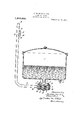
With these ends in view our improvements comprise features which are illustrated in their preferred embodiment in the drawing accompanying this specification, wherein the figure is a side elevation, largely in section,
of a tank and auge to which our improvements are applied.
Gauges of the general class of which we have knowledge, while in many cases giving excellent service in stationary installations, have been unsatisfactory because of inaccuracy when applied to moving vehicles, such as automobiles. In such service the car on which they are mounted is subject to the unevennesses of the road and particularly in goin up and down hills, when the gauge is liaile to such changes of relation to the tank as to cause the reading to be erroneous. In our improvements we have eliminated these difliculties and have provided a gauge of accuracy and reliability.
Directing attention now to the drawings, 2 is a tank, such for instance as is adapted for holdin the gasoline supply in an automobile. his tank may be rovided with the usual supply pipe 21 leading to the engine, not shown. It is also provided with a pipe 3, preferably leading from the bottom of the tank and communicating with the upper face of diaphragm 7, in diaphragm box 5. This ipe 3 may be conveniently enlarged at its ower end to form a receiving 7 chamber 4 in the upper part of box 5. Said box is divided through its mid-portion by rigid wall 6, and spaced apart therein above and below said rigid wall are diaphragms 7 and 8 respectively, whereby are formed chambers 9,and 10. The lower face of diaphragm 8 may be exposed to the atmosphere, or said diaphragm may form the upper wall of an expansion chamber 22 containing air, and which chamber may be closed by a plug, not shown, in outlet 23, to keep said diaphragm free of dirt. The terms upper and ower as applied to chambers 9 and 10 are relative only, as said box 5 may with equal efficiency be placed on its side with diaphragms 7 and 8 in vertical positions, or said box may be arranged in any other convenient position.
Connected with chamber 9 is one end of pipe 11, of small calibre, and which pipe leads from said chamber to some convenient place of observation, preferably to gauge glass 19 inserted in said pipe at scale 12, conveniently located for reading, as for instance on the instrument board of the automobile, not shown, in which automobile the gasoline tank is installed. Said pipe 11 after passing said scale makes a return bend at 13 and the other end, 14, of said pipe is connected with chamber 10 of the diaphragm box. That portion of pipe 11 comprised of gauge glass 19 being transparent the contents of said pipe are visible therethrough. \Vhile it would be theoretically acceptable to have the whole of pipe 11 of glass, it is obvious that all but that ortion adjacent the scale is preferably mad of metal so as to withstand bendin and shocks incident to a moving vehicle. hambers 9 and 10 may be provided with openings 15 and 16 respectively, closed by plugs as shown, for the purpose of filling the gauge system with an indicating fluid, such as colored alcohol.
In the drawing, tank 2 is illustrated as about half filled and bubble 17 is shown at a proportionate height against scale 12. As the contents of tank 2 are withdrawn, the weight of the column on top of diaphragm 7 is correspondingly decreased, thus permitting said diaphragm to move upwardly, whereby the size of chamber 9 is increased and a small portion of the liquid from ipe 11 flows thereinto, thereby lowering bu ble 17 a proportionate amount, and a small portion of the liquid in chamber 10 flows outwardly into return pipe 14 and thence into gau glass 19 following bubble 17 downwar ly.
We claim:
1. In a gau e for fluids the combination of a tank for t e liquid to be gauged, a diaphra 111 box below said tank inc uding two cham rs separated by a rigid wall, each of said chambers having a yieldable diaphra forming one wall thereof, a communicating passage from said tank to the outer face of one of said diaphragms, a ipe leading from one of said chambers an back to the other chamber, and a transparent ortion in said ipe, said chambers and said pipe being fifled with a liquid except for the resence of a bubble of air therein, and said bubble of air being located within the transparent portion of said dpipe. 55 2. In a gauge for flui s the combination of a tank for the liquid to be gauged, :1 diaphragm box below said tank including two chambers separated by a rigid wall, each of said chambers having a yieldable diaphragm forming one wall thereof, a communicating passage from said tank to the outer face of one 0 said diaphragms, a scale, a pipe leading from one of said chambers to said scale and back to the other chamber, and a trans 65 parent portion in said pipe opposite said scale. said chambers and said pipe being filled with a liquid except for the presence of a bubble of air thereln, and said bubble of air being located within the transparent portion of said pipe.
3. In a gauge for fluids the combination of a tank for the liquid to be gauged, a diaphragm box below said tank including two chambers separated by a rigid wall, each of said chambers havin a yieldable diaphragm forming one wafi thereof, a chamber above one of said diaphragms the lower wall of which is formed by said diaphragm, a chamber below the other diaphragm the upper wall of which is formed y said other dialphragm, means for permitting access of t e liquid to be gauged to the outer face of the diaphragm of one of the two chambers separated by the rigid wall, a pipe leading from one of the chambers separated by said rigid wall to the other thereof, a transparent portion in said pipe, said pipe being filled with a liquid except for the resence of a bubble of air therein, and sai bubble of air being located within the transparent portion of said pipe.
4. In a gauge for fluids the combination of a diaphragm box including two chambers separated by a rigid wall, each of said chambers having a yieldable diaphragm forming one wall thereof, a pipe leading from one of said chambers and back to the other chamber, a transparent portion in said pipe, said pipe being filled with a liquid except for the resence of a bubble of air therein, 100 said bub le of air being located within the transparent portion of said ipe, and means for permitting access of t e liquid to be gauged to the outer face of the diaphra m of one of the two chambers separated y 105 the rigid wall.
5. In a liquid level gauge the combination of a box including two chambers separated by a rigid wall, each of said chambers having a yieldable 'wall, a pipe containing 110 liquid and leading from one of said chambers back to the other chamber, a transparent portion in said pipe, means in the iquid in said pipe located within the transparent portion thereof for indicating the 11 eight of the liquid to be gauged, and means for permitting access of the liquid to be gen (1 to the outer face of the yieldable wal of one of said two chambers.
6. In a liquid level auge the combination 120 of two chambers, eac having a yieldable wall, a pipe containing fluid leading from one of sai chambers back to the other chamber, a transparent portion in said pipe, means in the fluid in said pi located with- 125 in the transparent portion t ereof for indicating the height of the liquid to be gauged, and means for permitting access of the liquid to be aged to the outer face of the yieldable we I of one of said two chambers.
7. In a. liquid level gauge the combination liquid to be gauged to the outer face of the of two chambers, each havin a yieldable yieldable wall of one of said two chambers. Wall, a pi e containing fluid iading from In witness whereof, we hereby affix our 10 one of sai chambers back to the other chamsignatures this 24th day of December, 1920. 5 her, means in a portion of said pipe for indicating the height of the liquid to be gauged ABRAHAM NOVICK. and means for permitting access of the EDWARD FISH.
Certificate of Correction.
It is hereby certified that in Letters Patent No. 1,413,235, granted April 18, 1922, upon the application of Abraham Novick, of Brooklyn, and Edward Fish,
of New York,N. Y., for an improvement in Liquid-Level Gauges," errors appear in the printed specification requiring correction as follows: Page 2, lines 40, 55, 71 and 92, claims 1, 2, 3 and 4, for the words "gauge for fluids" read liquid level gauge; and that the said Letters Patent should be read with these corrections therein that the same may conform to the record of the case in the Patent Office.
Signed and sealed this 9th day of May, A. D., 1922.
sun KARL FENNING,
Acting Commissioner of Patents.
Priority Applications (1)
| Application Number | Priority Date | Filing Date | Title |
|---|---|---|---|
| US433627A US1413235A (en) | 1920-12-28 | 1920-12-28 | Liquid-level gauge |
Applications Claiming Priority (1)
| Application Number | Priority Date | Filing Date | Title |
|---|---|---|---|
| US433627A US1413235A (en) | 1920-12-28 | 1920-12-28 | Liquid-level gauge |
Publications (1)
| Publication Number | Publication Date |
|---|---|
| US1413235A true US1413235A (en) | 1922-04-18 |
Family
ID=23720890
Family Applications (1)
| Application Number | Title | Priority Date | Filing Date |
|---|---|---|---|
| US433627A Expired - Lifetime US1413235A (en) | 1920-12-28 | 1920-12-28 | Liquid-level gauge |
Country Status (1)
| Country | Link |
|---|---|
| US (1) | US1413235A (en) |
Cited By (5)
| Publication number | Priority date | Publication date | Assignee | Title |
|---|---|---|---|---|
| US2653477A (en) * | 1949-12-29 | 1953-09-29 | Elvin E Hoskins | Liquid level gauge |
| US2945058A (en) * | 1957-09-11 | 1960-07-12 | Eastman Kodak Co | Manufacture of crotonic acid |
| US4336825A (en) * | 1980-06-17 | 1982-06-29 | Factory Mutual Research Corporation | Liquid level control system |
| US5063778A (en) * | 1990-07-02 | 1991-11-12 | Jorritsma Johannes N | Apparatus for measuring the level of a liquid in a wetwell |
| US5528941A (en) * | 1993-04-14 | 1996-06-25 | Sumitomo Wiring Systems, Ltd. | Differential pressure sensor connector for fuel tank |
-
1920
- 1920-12-28 US US433627A patent/US1413235A/en not_active Expired - Lifetime
Cited By (5)
| Publication number | Priority date | Publication date | Assignee | Title |
|---|---|---|---|---|
| US2653477A (en) * | 1949-12-29 | 1953-09-29 | Elvin E Hoskins | Liquid level gauge |
| US2945058A (en) * | 1957-09-11 | 1960-07-12 | Eastman Kodak Co | Manufacture of crotonic acid |
| US4336825A (en) * | 1980-06-17 | 1982-06-29 | Factory Mutual Research Corporation | Liquid level control system |
| US5063778A (en) * | 1990-07-02 | 1991-11-12 | Jorritsma Johannes N | Apparatus for measuring the level of a liquid in a wetwell |
| US5528941A (en) * | 1993-04-14 | 1996-06-25 | Sumitomo Wiring Systems, Ltd. | Differential pressure sensor connector for fuel tank |
Similar Documents
| Publication | Publication Date | Title |
|---|---|---|
| US1885926A (en) | Liquid measuring device | |
| US1413235A (en) | Liquid-level gauge | |
| US2168885A (en) | Grade indicator | |
| US1590287A (en) | Liquid-level indicator | |
| US1646957A (en) | Liquid-level indicator | |
| US1646311A (en) | Depth indicator | |
| US2153450A (en) | Single head meter | |
| US1983231A (en) | Fluid meter | |
| US1656262A (en) | batchelder | |
| US1656068A (en) | Liquid-level gauge | |
| US1394336A (en) | Gage | |
| US1878867A (en) | Radiator water level indicator | |
| US1570481A (en) | Liquid-registering device | |
| US1526850A (en) | Device for indicating liquid level and composition | |
| US3036463A (en) | Liquid level pressure transducer and indicating device | |
| US1629992A (en) | Liquid gauge | |
| US1706958A (en) | Liquid-level indicator | |
| US1880236A (en) | Gauge | |
| US1394031A (en) | Liquid-level gage | |
| US1396273A (en) | Gage or indicator for fluid-holding tanks | |
| US1675698A (en) | Liquid-level indicator | |
| US1560343A (en) | Liquid-level gauge | |
| US1670578A (en) | Liquid-level gauge | |
| US1791349A (en) | Liquid-dispensing machine | |
| US1823491A (en) | Liquid level gauge |