US1382199A - Metal pole, girder, or beam - Google Patents
Metal pole, girder, or beam Download PDFInfo
- Publication number
- US1382199A US1382199A US375656A US37565620A US1382199A US 1382199 A US1382199 A US 1382199A US 375656 A US375656 A US 375656A US 37565620 A US37565620 A US 37565620A US 1382199 A US1382199 A US 1382199A
- Authority
- US
- United States
- Prior art keywords
- portions
- web
- girder
- section
- pole
- Prior art date
- Legal status (The legal status is an assumption and is not a legal conclusion. Google has not performed a legal analysis and makes no representation as to the accuracy of the status listed.)
- Expired - Lifetime
Links
Images
Classifications
-
- E—FIXED CONSTRUCTIONS
- E04—BUILDING
- E04H—BUILDINGS OR LIKE STRUCTURES FOR PARTICULAR PURPOSES; SWIMMING OR SPLASH BATHS OR POOLS; MASTS; FENCING; TENTS OR CANOPIES, IN GENERAL
- E04H12/00—Towers; Masts or poles; Chimney stacks; Water-towers; Methods of erecting such structures
- E04H12/02—Structures made of specified materials
- E04H12/08—Structures made of specified materials of metal
- E04H12/10—Truss-like structures
Definitions
- My present invention relates to such structures as. hollow metal poles, beams, box girders and the like and the object is to provide a box pole or girder construction which requires the handling of but few parts and which can be formed of standard rolled sections having great strength.
- a further object is to substitute presswork for the usual fabrication, thereby quickening and simplifying the process of manufacture and naturally resulting in lowered cost.
- the invention consists in the improved construction of metal pole, girder, beam or the like as hereinafter more particularly described and then specified in the claims.
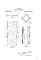
- Figure 1 is an end view of a rolled section of standard shape which is preferably used in carrying out this invention.
- Fig. 2 is a plan of the same, showing the cuts subdividing the web.
- Fig. 3 is a transverse cross-section taken on the line 3--3 Fig. 2 and shows the structure after the parts have been bent or formed into finished shape.
- v y is a transverse cross-section taken on the line 3--3 Fig. 2 and shows the structure after the parts have been bent or formed into finished shape.
- Fig. 4 is a side elevation of a portion of the finished pole or beam, the tying members being shown in section.
- girder or beam I employ a rolled section having longitudinally flanged edges and by prefer ence use a standard I-beam of a size suitable for the size pole or beam desired.
- 1 indicates the Web of. such a beam and 2 the flanges running along the longitudinal edges, which flanges, when an I- beam is employed, run in both directions from the web 1.
- the web as indicated in Fig. 2, is subdivided transversely into a plurality of portions or partsby cuts 3 which preferably run diagonally from one flanged edge 2 to the central line of the web and then diagonally in the opposite direction to the other flanged edge of the section.
- This cutting or subdividing may be done in a press or in any other desired manner and results in theformation of a number of portions separated from each other except at the flanged edges 2.
- alternate portions 4' are duplicates of each other and alternate portions 5 are duplicates of each other.
- the section is run through a suitable press, or by any other forming operation, the alternate portions 4 and the alternate portions 5 are bent transversely to the normal plane of the web.
- the parts 4 are all bent or expanded in the one direction and the parts 5 are all bent in the opposite direction, the bending being preferably continued until the structure has a hollow box-like appearance with square or flat sides as indicated in Fig. 3.
- portions 4 and 5 may be removed as indicated by the dotted lines 7 in Fig. 2.
- a metal pole or beam comprising a rolled section having flanged edges, the web of said section being divided into a plurality of portions bent alternately in opposite directions out of the normal plane of the web and members tying the projecting edges of said portions together.
- a metal pole or beam comprising a rolled section having longitudinally flanged edges, the web of said section being divided transversely into a plurality of portions bent alternately out of the normal plane of the web to form a hollow box-like structure and members engaging and tying together the free ends of the bent out portions.
- a metalpole or beam comprising a rolled section having longitudinally flanged edges, the web of said section being divided on diagonal lines into a plurality of portions, alternate portions being duplicates of each other and bent alternately in opposite directions from the normal plane of the weband longitudinal members tying the free ends of said outwardly bent portions together.
- a metal pole or beam comprising a rolled section having longitudinally flanged edges, the web of said section being divid'ed, by cuts-running diagonally from one flanged edge to the center line of the web and then diagonally but in the opposite directionto the other flanged edge, into a plurality of portions integral with the flanged edges, said portions being bent alternately in opposite directions from the normal plane of the web and, members tying the outer edges I of said outwardly bent portions together.
- a metal pole or post comprising a rolled section having longitudinal flanged edges, the web of said section being divided into a plurality of diamond shaped parts,
- alternate parts being duplicates of each other, said parts being bent alternately out of the normal plane of the web to form a box-like structure and members secured to and tying said parts together at their outwardly bent portions.
Landscapes
- Engineering & Computer Science (AREA)
- Architecture (AREA)
- Life Sciences & Earth Sciences (AREA)
- Chemical & Material Sciences (AREA)
- Materials Engineering (AREA)
- Wood Science & Technology (AREA)
- Civil Engineering (AREA)
- Structural Engineering (AREA)
- Rod-Shaped Construction Members (AREA)
Description
M. LACHMAN.
METAL POLE, GIRDER, 0R BEAM.
APPLICATION FILED APRJZ, I920.
Patented June 21, 1921.
3 V I W Y amvwwboz MflU/P/CE LAC'H/ /A/V @51 A 5 a ttomeg s UNITED STATES MAURICE LACHMAN, 'OF NEW YORK, N. Y.
METAL POLE, GIRDER, 0R BEAM.
Specification of Letters Patent.
Patented June 21, 1921.
Application filed April 22, 1920. Serial No. 375,656.
To all whom it may concem:
Be it known that I, MAURICE LACHMAN, a
citizen of the United States, and a resident of New York, in the county of New York and State of New York, have invented certain new and useful Improvements in Metal Poles, Girders, or Beams, of which the following is a specification.
My present invention relates to such structures as. hollow metal poles, beams, box girders and the like and the object is to provide a box pole or girder construction which requires the handling of but few parts and which can be formed of standard rolled sections having great strength.
A further object is to substitute presswork for the usual fabrication, thereby quickening and simplifying the process of manufacture and naturally resulting in lowered cost.
The invention consists in the improved construction of metal pole, girder, beam or the like as hereinafter more particularly described and then specified in the claims.
In the accompanying drawings, Figure 1 is an end view of a rolled section of standard shape which is preferably used in carrying out this invention.
Fig. 2 is a plan of the same, showing the cuts subdividing the web.
Fig. 3 is a transverse cross-section taken on the line 3--3 Fig. 2 and shows the structure after the parts have been bent or formed into finished shape. v y
Fig. 4 is a side elevation of a portion of the finished pole or beam, the tying members being shown in section. I
As to the main element of the pole, girder or beam I employ a rolled section having longitudinally flanged edges and by prefer ence use a standard I-beam of a size suitable for the size pole or beam desired. In the drawings, 1 indicates the Web of. such a beam and 2 the flanges running along the longitudinal edges, which flanges, when an I- beam is employed, run in both directions from the web 1. 1
The web, as indicated in Fig. 2, is subdivided transversely into a plurality of portions or partsby cuts 3 which preferably run diagonally from one flanged edge 2 to the central line of the web and then diagonally in the opposite direction to the other flanged edge of the section.
This cutting or subdividing may be done in a press or in any other desired manner and results in theformation of a number of portions separated from each other except at the flanged edges 2. I
By subdividing the web as shown alternate portions 4' are duplicates of each other and alternate portions 5 are duplicates of each other.
After subdivision, the section is run through a suitable press, or by any other forming operation, the alternate portions 4 and the alternate portions 5 are bent transversely to the normal plane of the web. The parts 4 are all bent or expanded in the one direction and the parts 5 are all bent in the opposite direction, the bending being preferably continued until the structure has a hollow box-like appearance with square or flat sides as indicated in Fig. 3.
6 indicates longitudinal members, preferably angle or L-shaped, which engage the outer free ends of both sets of outwardly bent portions l and 5. These members preferably engage the outermost part of the portions 4 and 5 and are riveted or welded to such portions to secure and eifectively tie the portions to each other.
1 In this manner a hollow trussed pole or girder is obtained without an fabrication whatever except the securing o the tie members 6.
If desired to simulate a latticed pole or if desired to lighten the structure parts of the portions 4 and 5 may be removed as indicated by the dotted lines 7 in Fig. 2.
What I claim as my invention is:
1. A metal pole or beam comprising a rolled section having flanged edges, the web of said section being divided into a plurality of portions bent alternately in opposite directions out of the normal plane of the web and members tying the projecting edges of said portions together..
2. A metal pole or beam comprising a rolled section having longitudinally flanged edges, the web of said section being divided transversely into a plurality of portions bent alternately out of the normal plane of the web to form a hollow box-like structure and members engaging and tying together the free ends of the bent out portions.
3. A metalpole or beam comprising a rolled section having longitudinally flanged edges, the web of said section being divided on diagonal lines into a plurality of portions, alternate portions being duplicates of each other and bent alternately in opposite directions from the normal plane of the weband longitudinal members tying the free ends of said outwardly bent portions together. I
4. A metal pole or beam comprising a rolled section having longitudinally flanged edges, the web of said section being divid'ed, by cuts-running diagonally from one flanged edge to the center line of the web and then diagonally but in the opposite directionto the other flanged edge, into a plurality of portions integral with the flanged edges, said portions being bent alternately in opposite directions from the normal plane of the web and, members tying the outer edges I of said outwardly bent portions together.
5. A metal pole or post comprising a rolled section having longitudinal flanged edges, the web of said section being divided into a plurality of diamond shaped parts,
alternate parts being duplicates of each other, said parts being bent alternately out of the normal plane of the web to form a box-like structure and members secured to and tying said parts together at their outwardly bent portions.
Signed at New York in the county of New Yorkand State of New York this 16th day of April, A. D. 1920.
MAURICE, LACHMAN.
Witness:
IRENE 'LEFKowITz.
Priority Applications (1)
| Application Number | Priority Date | Filing Date | Title |
|---|---|---|---|
| US375656A US1382199A (en) | 1920-04-22 | 1920-04-22 | Metal pole, girder, or beam |
Applications Claiming Priority (1)
| Application Number | Priority Date | Filing Date | Title |
|---|---|---|---|
| US375656A US1382199A (en) | 1920-04-22 | 1920-04-22 | Metal pole, girder, or beam |
Publications (1)
| Publication Number | Publication Date |
|---|---|
| US1382199A true US1382199A (en) | 1921-06-21 |
Family
ID=23481767
Family Applications (1)
| Application Number | Title | Priority Date | Filing Date |
|---|---|---|---|
| US375656A Expired - Lifetime US1382199A (en) | 1920-04-22 | 1920-04-22 | Metal pole, girder, or beam |
Country Status (1)
| Country | Link |
|---|---|
| US (1) | US1382199A (en) |
Cited By (4)
| Publication number | Priority date | Publication date | Assignee | Title |
|---|---|---|---|---|
| USD249069S (en) * | 1976-03-19 | 1978-08-22 | Construction Specialties, Inc. | Decorative screen for facades |
| US6386641B2 (en) * | 1999-04-22 | 2002-05-14 | Kennametal Pc Inc. | Weld joint design for corners |
| US8176699B1 (en) * | 2010-05-03 | 2012-05-15 | Birchfield Robert J | Hurricane truss roof system |
| US9371662B1 (en) * | 2015-03-31 | 2016-06-21 | Us Tower Corporation | Variable height telescoping lattice tower |
-
1920
- 1920-04-22 US US375656A patent/US1382199A/en not_active Expired - Lifetime
Cited By (7)
| Publication number | Priority date | Publication date | Assignee | Title |
|---|---|---|---|---|
| USD249069S (en) * | 1976-03-19 | 1978-08-22 | Construction Specialties, Inc. | Decorative screen for facades |
| US6386641B2 (en) * | 1999-04-22 | 2002-05-14 | Kennametal Pc Inc. | Weld joint design for corners |
| US8176699B1 (en) * | 2010-05-03 | 2012-05-15 | Birchfield Robert J | Hurricane truss roof system |
| US9371662B1 (en) * | 2015-03-31 | 2016-06-21 | Us Tower Corporation | Variable height telescoping lattice tower |
| US9523212B2 (en) | 2015-03-31 | 2016-12-20 | Us Tower Corporation | Variable height telescoping lattice tower |
| US20170096830A1 (en) * | 2015-03-31 | 2017-04-06 | US Tower Corp. | Variable height telescoping lattice tower |
| US10017954B2 (en) * | 2015-03-31 | 2018-07-10 | US Tower Corp. | Variable height telescoping lattice tower |
Similar Documents
| Publication | Publication Date | Title |
|---|---|---|
| US2065378A (en) | Structural shape | |
| US1741423A (en) | Girder | |
| US1645060A (en) | Truss construction | |
| US1865059A (en) | Girder construction | |
| US1498176A (en) | Tapered metal pole | |
| US1382199A (en) | Metal pole, girder, or beam | |
| US2052024A (en) | Metal stud for buildings | |
| US1918345A (en) | Joist, beam, girder, and the like | |
| US1936536A (en) | Flooring structure | |
| US2465074A (en) | Structural member | |
| US1100742A (en) | Concrete-reinforcing bar. | |
| US2142637A (en) | Lota-beam | |
| US1864043A (en) | Form for making fireproof floor constructions | |
| US1696039A (en) | Joist | |
| US2155694A (en) | Grating | |
| US1880003A (en) | Method of making metal structures | |
| US2207952A (en) | Structural unit and method of making it | |
| US1748423A (en) | Method of making structural units | |
| US1824091A (en) | Structural building unit | |
| US2097722A (en) | Joist | |
| US1933253A (en) | Blank for and method of making load bearing members | |
| US1698081A (en) | Metallic floor joist | |
| US1935758A (en) | Truss | |
| US1822331A (en) | Expanded metal joist | |
| US1006047A (en) | Trussed structure. |