US1336294A - Bed-rest - Google Patents
Bed-rest Download PDFInfo
- Publication number
- US1336294A US1336294A US311913A US31191319A US1336294A US 1336294 A US1336294 A US 1336294A US 311913 A US311913 A US 311913A US 31191319 A US31191319 A US 31191319A US 1336294 A US1336294 A US 1336294A
- Authority
- US
- United States
- Prior art keywords
- support
- base
- rest
- bed
- sleeves
- Prior art date
- Legal status (The legal status is an assumption and is not a legal conclusion. Google has not performed a legal analysis and makes no representation as to the accuracy of the status listed.)
- Expired - Lifetime
Links
- 229910000746 Structural steel Inorganic materials 0.000 description 5
- 239000000945 filler Substances 0.000 description 3
- 239000002023 wood Substances 0.000 description 3
- 238000010276 construction Methods 0.000 description 2
- 230000009975 flexible effect Effects 0.000 description 2
- 235000000396 iron Nutrition 0.000 description 2
- 241000905957 Channa melasoma Species 0.000 description 1
- 230000004075 alteration Effects 0.000 description 1
- 239000000463 material Substances 0.000 description 1
Images
Classifications
-
- A—HUMAN NECESSITIES
- A47—FURNITURE; DOMESTIC ARTICLES OR APPLIANCES; COFFEE MILLS; SPICE MILLS; SUCTION CLEANERS IN GENERAL
- A47C—CHAIRS; SOFAS; BEDS
- A47C20/00—Head-, foot- or like rests for beds, sofas or the like
- A47C20/02—Head-, foot- or like rests for beds, sofas or the like of detachable type
- A47C20/027—Back supports, e.g. for sitting in bed
-
- A—HUMAN NECESSITIES
- A47—FURNITURE; DOMESTIC ARTICLES OR APPLIANCES; COFFEE MILLS; SPICE MILLS; SUCTION CLEANERS IN GENERAL
- A47C—CHAIRS; SOFAS; BEDS
- A47C20/00—Head-, foot- or like rests for beds, sofas or the like
- A47C20/04—Head-, foot- or like rests for beds, sofas or the like with adjustable inclination
- A47C20/042—Head-, foot- or like rests for beds, sofas or the like with adjustable inclination by means of screw-and-nut mechanism
Definitions
- This invention relates to improvements in bed rests, an object of the invention being to provide a rest which may be located at the desired angle, which can be easily adj usted from one angle to another, and which, when not in use, will occupy but a small space.
- a further object is to provide a device of the character stated which can be manu factured and sold at a reasonably low price and will most eiiiciently perform the functions for which it is intended.
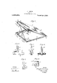
- Figure 1 is a perspective view illustrating my improvements
- Fig. 2 is an enlarged detail view in eleva tion illustrating the mounting of one of the sleeves 10;
- Fig. 3 is a similar view at right angles to Fig. 2, the angle iron 3 being in section;
- Figs. 4 and 5 are views similar to Figs. 2 and 3 illustrating a sleeve 1a ,and its cooperating parts;
- Fig. 6 is an enlarged view in transverse section through one of the side members of the support 27 1 represents a base, and 2 a support.
- the support 2 comprises a pair of angle irons 3 parallel to each other having wood fillers 4: and connected by a canvas or other flexible sheet 5, which is secured to the wood filler by extending the sheet around the same and employing ordinary tacks or other securing devices 20.
- the base 1 is formed of angle iron 6 and the support 2 is connected to one end of the base by means of pivots 7, which may con stitute ordinary rivets or bolts which extend through the angle irons of the base and support.
- the base is strengthened by braces Specification of Letters Patent.
- guide rods 9 are fixed on the end portion of the base 1 guide rods 9 are fixed. These rods are horizontal and spaced from the base so as to make ample provision for the sliding movement of sleeves 10 mounted to move freely on the guide rods 9.
- the support 2 at its free end is made with depending perforated lugs 18 constituting bearings for a rod 17.
- This rod 17 has right and left hand screw threads illustrated at 17 at opposite sides of its center and the said screw threaded aortions engage the internally screw threaded sleeves 14- which are caused to move toward and away from the center of the rodwhen the rod is turned by means of a crank handle 19 removably connected to one end thereof.
- the sleeves 14 and 10 are connected by a lazy tong 12, the members of which are preferably of channel construction for strength and the ends are bifurcated, as shown at 13, for the attachment of the tong to the sleeves.
- a device of the character described comprising a rectangular angle iron base, a support pivotally connected at one end to the base, said support comprising an angle iron frame, wood fillers secured in the angle iron side members of the support, a sheet of flex ible material secured across the side members of said support, perforated lugs at the free ends of the side members of the support, a screw threaded rod in said lugs, guide rods on the base. sleeves on the screw threaded rod and on the guide rods, and a toggle lever connecting said sleeves.
Landscapes
- Health & Medical Sciences (AREA)
- General Health & Medical Sciences (AREA)
- Nursing (AREA)
- Orthopedics, Nursing, And Contraception (AREA)
Description
A. HACKMAN.
BED REST.
APPLICATION FILED JULY 19. I919.
' 1 36,294, Patented Apr. 6, 1920.
M By
4 TTORNE Y8 UNITED STATES PATENT OFFICE.
.AMANIDES HACKMAN, OF ALLENTOWN, PENNSYLVANIA.
BED-REST.
Application filed. July 19, 1919.
To all whom it may concern:
Be it known that I, AMANDns HAOKMAN, a citizen of the United States, and a resident of Allentown, in the county of Lehigh and State of Pennsylvania, have invented a new and Improved Bed-Rest, of which the following is a full, clear, and exact description.
This invention relates to improvements in bed rests, an object of the invention being to provide a rest which may be located at the desired angle, which can be easily adj usted from one angle to another, and which, when not in use, will occupy but a small space.
A further object is to provide a device of the character stated which can be manu factured and sold at a reasonably low price and will most eiiiciently perform the functions for which it is intended.
With these and other objects in view the invention consists in. certain novel features of construction, and combinations and arrangements of parts, as will be more fully hereinafter described and pointed out in the claim.
In the accompanying drawings-.-
Figure 1 is a perspective view illustrating my improvements;
Fig. 2 is an enlarged detail view in eleva tion illustrating the mounting of one of the sleeves 10;
Fig. 3 is a similar view at right angles to Fig. 2, the angle iron 3 being in section;
Figs. 4 and 5 are views similar to Figs. 2 and 3 illustrating a sleeve 1a ,and its cooperating parts; and
Fig. 6 is an enlarged view in transverse section through one of the side members of the support 27 1 represents a base, and 2 a support. The support 2 comprises a pair of angle irons 3 parallel to each other having wood fillers 4: and connected by a canvas or other flexible sheet 5, which is secured to the wood filler by extending the sheet around the same and employing ordinary tacks or other securing devices 20.
The base 1 is formed of angle iron 6 and the support 2 is connected to one end of the base by means of pivots 7, which may con stitute ordinary rivets or bolts which extend through the angle irons of the base and support. The base is strengthened by braces Specification of Letters Patent.
Patented Apr. 6, 1920.
Serial No. 311,913.
8 which connect the side members with the end member of the base and as many of such braces may be employed as desired.
On the end portion of the base 1 guide rods 9 are fixed. These rods are horizontal and spaced from the base so as to make ample provision for the sliding movement of sleeves 10 mounted to move freely on the guide rods 9. The support 2 at its free end is made with depending perforated lugs 18 constituting bearings for a rod 17. This rod 17 has right and left hand screw threads illustrated at 17 at opposite sides of its center and the said screw threaded aortions engage the internally screw threaded sleeves 14- which are caused to move toward and away from the center of the rodwhen the rod is turned by means of a crank handle 19 removably connected to one end thereof. The sleeves 14 and 10 are connected by a lazy tong 12, the members of which are preferably of channel construction for strength and the ends are bifurcated, as shown at 13, for the attachment of the tong to the sleeves.
The operation is as follows: When the rod 17 is turned, the sleeves 14 and 10 will be caused to move laterally and adjust the support 2 vertically so that the support may be positioned at any angle and will be socurely held at any point of adjustment.
Various slight changes may be made in the general form and arrangement of parts described without departing from the invention, and hence I do not limit myself to the precise details set forth but consider myself at liberty to make such changes and alterations as fairly fall within the spirit and scope of the appended claim.
I claim:
A device of the character described, comprising a rectangular angle iron base, a support pivotally connected at one end to the base, said support comprising an angle iron frame, wood fillers secured in the angle iron side members of the support, a sheet of flex ible material secured across the side members of said support, perforated lugs at the free ends of the side members of the support, a screw threaded rod in said lugs, guide rods on the base. sleeves on the screw threaded rod and on the guide rods, and a toggle lever connecting said sleeves.
AMANDES HACKMAN.
Priority Applications (1)
| Application Number | Priority Date | Filing Date | Title |
|---|---|---|---|
| US311913A US1336294A (en) | 1919-07-19 | 1919-07-19 | Bed-rest |
Applications Claiming Priority (1)
| Application Number | Priority Date | Filing Date | Title |
|---|---|---|---|
| US311913A US1336294A (en) | 1919-07-19 | 1919-07-19 | Bed-rest |
Publications (1)
| Publication Number | Publication Date |
|---|---|
| US1336294A true US1336294A (en) | 1920-04-06 |
Family
ID=23209035
Family Applications (1)
| Application Number | Title | Priority Date | Filing Date |
|---|---|---|---|
| US311913A Expired - Lifetime US1336294A (en) | 1919-07-19 | 1919-07-19 | Bed-rest |
Country Status (1)
| Country | Link |
|---|---|
| US (1) | US1336294A (en) |
Cited By (9)
| Publication number | Priority date | Publication date | Assignee | Title |
|---|---|---|---|---|
| US2788529A (en) * | 1954-09-28 | 1957-04-16 | Moritzacky Fred | Adjustable headrest for beds |
| US2954566A (en) * | 1957-03-19 | 1960-10-04 | Trea Boye Corp | Toilet structure |
| US3343184A (en) * | 1965-10-24 | 1967-09-26 | Nathan H Friedman | Foot board |
| US4853990A (en) * | 1986-12-29 | 1989-08-08 | Mechanical Backrest, Inc. | Mechanical backlift |
| EP0505847A1 (en) * | 1991-03-28 | 1992-09-30 | Dewert Antriebs- und Systemtechnik GmbH & Co. KG | Lifting device |
| US20030093074A1 (en) * | 2000-10-05 | 2003-05-15 | Burl Pettibon | Spinal adjusting device and method |
| US20110168062A1 (en) * | 2010-01-08 | 2011-07-14 | Dellavecchia Michael | Mechanically adjustable work station with optional retractable work support ledge |
| US8323223B1 (en) * | 2009-02-14 | 2012-12-04 | Woggon Dennis A | Mechanical drop traction apparatus |
| US10524594B2 (en) * | 2017-01-10 | 2020-01-07 | Xiamen Baby Pretty Products Co., Ltd. | Portable baby sleeping bag |
-
1919
- 1919-07-19 US US311913A patent/US1336294A/en not_active Expired - Lifetime
Cited By (11)
| Publication number | Priority date | Publication date | Assignee | Title |
|---|---|---|---|---|
| US2788529A (en) * | 1954-09-28 | 1957-04-16 | Moritzacky Fred | Adjustable headrest for beds |
| US2954566A (en) * | 1957-03-19 | 1960-10-04 | Trea Boye Corp | Toilet structure |
| US3343184A (en) * | 1965-10-24 | 1967-09-26 | Nathan H Friedman | Foot board |
| US4853990A (en) * | 1986-12-29 | 1989-08-08 | Mechanical Backrest, Inc. | Mechanical backlift |
| EP0505847A1 (en) * | 1991-03-28 | 1992-09-30 | Dewert Antriebs- und Systemtechnik GmbH & Co. KG | Lifting device |
| US5305482A (en) * | 1991-03-28 | 1994-04-26 | Dewert Antriebs-Und Systemtechnik Gmbh & Co Kg | Lifting device |
| US20030093074A1 (en) * | 2000-10-05 | 2003-05-15 | Burl Pettibon | Spinal adjusting device and method |
| US7322977B2 (en) * | 2000-10-05 | 2008-01-29 | Burl Pettibon | Spinal adjusting device and method |
| US8323223B1 (en) * | 2009-02-14 | 2012-12-04 | Woggon Dennis A | Mechanical drop traction apparatus |
| US20110168062A1 (en) * | 2010-01-08 | 2011-07-14 | Dellavecchia Michael | Mechanically adjustable work station with optional retractable work support ledge |
| US10524594B2 (en) * | 2017-01-10 | 2020-01-07 | Xiamen Baby Pretty Products Co., Ltd. | Portable baby sleeping bag |
Similar Documents
| Publication | Publication Date | Title |
|---|---|---|
| US2703265A (en) | Adjustable platform supporting bedrail bracket means | |
| US1631355A (en) | Embroidery-hoop clamp | |
| US1938006A (en) | Manipulative table for spinal correction | |
| US1336294A (en) | Bed-rest | |
| US1082043A (en) | Operating adjustable table. | |
| US1420404A (en) | School desk | |
| US808217A (en) | Pillow. | |
| US1417565A (en) | Motorman's stool | |
| US2908917A (en) | Rocking cradle and high chair device | |
| US1318271A (en) | Hospital-bed. | |
| US1343163A (en) | Drum-beater | |
| US1368957A (en) | Ellen j | |
| US1639462A (en) | Mattress-adjusting apparatus | |
| US1214584A (en) | Adjustable support. | |
| US1604945A (en) | Mechanical drum beater | |
| US1295753A (en) | Obstetrical saddle. | |
| US1319445A (en) | Adjustable table | |
| US189943A (en) | Improvement in bed-bottoms | |
| US251630A (en) | Feedeeic a | |
| US2079759A (en) | Apparatus for controlling an iron cord | |
| US2082131A (en) | Bed | |
| US136271A (en) | Improvement in wire-mattress frames | |
| US1372261A (en) | Adjustable table | |
| US822443A (en) | Bed-bottom. | |
| US1731324A (en) | Double ironing board |