US1325549A - Cooks - Google Patents
Cooks Download PDFInfo
- Publication number
- US1325549A US1325549A US1325549DA US1325549A US 1325549 A US1325549 A US 1325549A US 1325549D A US1325549D A US 1325549DA US 1325549 A US1325549 A US 1325549A
- Authority
- US
- United States
- Prior art keywords
- plug
- chamber
- sleeve
- sparking
- shoulder
- Prior art date
- Legal status (The legal status is an assumption and is not a legal conclusion. Google has not performed a legal analysis and makes no representation as to the accuracy of the status listed.)
- Expired - Lifetime
Links
- 210000002816 Gills Anatomy 0.000 description 6
- 238000001816 cooling Methods 0.000 description 6
- 239000002184 metal Substances 0.000 description 6
- 230000000875 corresponding Effects 0.000 description 4
- 210000000088 Lip Anatomy 0.000 description 2
- 150000001768 cations Chemical class 0.000 description 2
- 238000002485 combustion reaction Methods 0.000 description 2
- 230000004048 modification Effects 0.000 description 2
- 238000006011 modification reaction Methods 0.000 description 2
- 230000036633 rest Effects 0.000 description 2
- 241000894007 species Species 0.000 description 2
Images

Classifications
-
- H—ELECTRICITY
- H01—ELECTRIC ELEMENTS
- H01B—CABLES; CONDUCTORS; INSULATORS; SELECTION OF MATERIALS FOR THEIR CONDUCTIVE, INSULATING OR DIELECTRIC PROPERTIES
- H01B17/00—Insulators or insulating bodies characterised by their form
- H01B17/54—Insulators or insulating bodies characterised by their form having heating or cooling devices
Definitions
- SHEETSSHEET 2- a Amswra Jim me; J0 14744000103 MICHAEL JOHN WILLCOCKS, F CLEVEDON, ENGLAND.
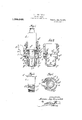
- Figure 1 is a view partly in section and partly in elevation o f a plug constructed in accordance with the invention.
- Fi 2 is a sectional view of the body of the p ugdetached.
- Fig. 3 is an elevation of the sleeve employed. v I
- Big. 4 is a sectional plan vlew takenon line 11 of Fig. 1.
- Fig. 5 is a fragmentary sectional view showing a modified arrangement of sleeve.
- Fig. 6 is a sectional view taken on line 2-2 of Fig; 5.
- Fig. 7 is a fragmentary sectional view showlng the cooling chamber formed in the metal of the plhg.-
- Fig. 8 is a sectional plan view taken on line 33 of said Fig. 7.
- t Fig. 9 is a fragmentary sectional plan view showing another manner of forming tllle cooling chamber in the metal of the p ug.
- Fig. 10 is a sectional plan view taken on line 4-4 of said Fig. 9.
- Fig. 11 is a fragmentary sectional view showin a still further manner of forming the coo ing chamber.
- Fig. 12 is a sectional plan View taken on line 55 of said Fig. 11.
- the annular chamber a is formed in the metal portion 7) of the plug which screws into the engine cylinder by turning away a portion of the outer wall 6 to the required depth and then inserting a sleeve 0 provided with a flange c which rests on the shoulder b -against which the insulating interior 03 would ordinarily be butted, so that when said insulating interior a?
- a lateral passages a, a are provided, which passages a, a put the interior of said chamber a into communication with the external atmosphere,the passage a being connected to-a funnel e, the mouth 6 of which is made toface the direction in which the engine carrying the sparking plug moves, so that air forced into the chamber athrough passage a will escape by the passage a opposite.
- bafiie plate a against which the incoming air impinges and is deflected downward before issuing from the lateral passage a said baflle plate a being preferably constituted by angle-shaped plates located on the inner wall joining the air passages a, a and secured to said wall and the flanges of the funnel c. by rivets or other suitable means, and to insure a more efficient cooling of the sleeve 0, the same is, at its reduced portion 0 provided with a series of superimposed external gills taking in the lower part of the annular chamber a.
- two or more air inlets or lateral passages may be employed and con. nected up with the beforementioned funnel, or be connected up with a fan or blower.
- the sleeve 0 instead of being made stepped or of two diameters and provided with an externally threaded shoulder and with gills, is now made plain and of one diameter and its end portion 0 passed through an untapped hole 5 in the end 6* of the plug and welded thereto and then spun over an inwardly directed lip on said end 6 to hold in position a point carrying ring f.
- the plug portion 7) may, as shown in Figs. 7 and 8, be machined from upper part to provide an annular chamber a within it, a thin cylindrical wall 0 being left between the machined part and the portion within which the insulating interior, not shown, fits, and the end 0 of the wall a spun over on to the shoulder 72 as shown in full lines to close the chamber a, or, as shown in dotted lines, and, further, may be. welded to the opposite wall.
- the plug may be machined from its sparking end, as shown in Figs. 9 and 10, and .the end 0 of the cylindrical wall 0 be spun over the end I) of the plug and be welded thereto.
- the same may be replaced, as shown in Figs. 11 and 12, by a number of longitudinal passages a drilled in the body portion of the plug, the ends of the passages which are toward the engine being closed by plugs a and a corresponding number of lateral passages a drilled from the exterior to meet the longitudinal passages 0 so that the external atmosphere is admitted to said longitudinal passages a. the circulation in these passages being by convection.
- the air inlets may, as in the first described and shown arrangement, be connected to an inlet funnel.
- an anular chamber which is absolutely gas or fluidtight in relation to the combustion chamber or cylinder, located within the plug and at the sparking end thereof, said chamber being formed by the outer wall of the plug. the shoulder thereon and sparking end thereof, and an unperforated and externally gilled sleeve which makes a gas or fluidtight joint with said shoulder and sparking end, said chamber, which incloses the insulating interior, being provided with inlet and outlet passages located between any point where the insulating interior or its washer makes contact with the body of the plug or sleeve and the surface of the cylin- 2.
- An air-cooled, spark plug including a plu bodyhaving its sparking end formed hol ow, and provided with ports open to the atmosphere and also an interior shoulder above the ports, and a sleeve arranged within the hollow portion of the plug body to provide an annular chamber, said sleeve being of two difl'erent diameters, the larger of which is provided with an outwardly extending flange, while the smaller is provided with a series of external gills and at its lower end with an externally screw threaded portion adapted to screw into the sparking end of th plug body while said flange abuts against the shoulder above the ports, whereby when said sleeve is screwed into the sparking end and spun thereover and the flange of the sleeve is pressed onto the shoulder of the plug by the insulating interior and its nut, an eflicient joint is provided for the annular chamber.
- An air-cooled spark plug having its sparking end formed hollow and provided with ports open to the atmosphere, a sleeve fitted in the sparking end of the plug body to fgrovlde an annular interior chamber, and ba e plates arranged in the upper part of the annular chamber and between the said ports, whereby air entering one of the same Wlll be deflected down into the bottom of the chamber.
- a spark plug including a plug body havlng its sparking end formed with a chamber of relatively large diameter and provided with inlet and outlet ports, a sleeve adapted to be fitted within the chamber and provided at its upper end with a flange whereby when its lower end is fitted to the bottom portion of the plug body the said flange may be drawn tightly against an abutting part of the plug body above the ranged therein to form an annular air chamber in communication with said port and located at the sparking end of the plug.
Landscapes
- Spark Plugs (AREA)
Description
M. J. WILLCOCKS.-
SPARKING PLUG.
APPLICATION FI'LED SEPT-28.1918.
2 SHEETS-SHEET I.
M. J. WILLCOCKS.
SPARKING PLUG.
APPLICATION FILED SEPT.28. 1918:
1 $25,549. Patented Dec. 23, 1919.
2 SHEETSSHEET 2- a Amswra Jim me; J0 14744000103 MICHAEL JOHN WILLCOCKS, F CLEVEDON, ENGLAND.
SPARKING PLUG.
Specification of I.etters Patent. Patented Dec, 23, 1919 Application filed September 28, 1918. Serial No. 256,014.
To all whom, it may concern:
Be it known that I, MICHAEL JOHN W'ILL- COCKS, a subject of the King of Great Britain and Ireland, and a resident of Clevedon, county of Somerset, England, have invented a certain new and useful Improvement in or Relating to Sparkin Plugs, of which the following is a speci cation.
inder, located within the plug and at the sparking end thereof, said chamber being formed by the outer wall of the plug, the shoulder thereon and sparking end thereof, and an unperforated and externally gilled sleeve which makes a gas or fluid-tight joint with said shoulder and sparking end, said chamber, which incloses the insulating interior, being provided with inlet and outlet passages located between any point where the insulating interior or its washer makes contact with the body of the plug or sleeve and the surface of the cylinder. Theaccompanying sheets of drawin illustrate various ways of accomplishing t e in-' vention.-
Of the drawings Figure 1 is a view partly in section and partly in elevation o f a plug constructed in accordance with the invention.
Fig. 3 is an elevation of the sleeve employed. v I
Big. 4 is a sectional plan vlew takenon line 11 of Fig. 1.
Fig. 5 is a fragmentary sectional view showing a modified arrangement of sleeve.
Fig. 6 is a sectional view taken on line 2-2 of Fig; 5.
Fig. 7 is a fragmentary sectional view showlng the cooling chamber formed in the metal of the plhg.-
Fig. 8 is a sectional plan view taken on line 33 of said Fig. 7.
t Fig. 9 is a fragmentary sectional plan view showing another manner of forming tllle cooling chamber in the metal of the p ug.
Fig. 10 is a sectional plan view taken on line 4-4 of said Fig. 9.
Fig. 11 is a fragmentary sectional view showin a still further manner of forming the coo ing chamber.
Fig. 12 is a sectional plan View taken on line 55 of said Fig. 11.
Like letters of reference indicate corresponding parts in the several figures.
In carrying out the invention, and referring first to Figs. 1 to 4, the annular chamber a is formed in the metal portion 7) of the plug which screws into the engine cylinder by turning away a portion of the outer wall 6 to the required depth and then inserting a sleeve 0 provided with a flange c which rests on the shoulder b -against which the insulating interior 03 would ordinarily be butted, so that when said insulating interior a? is in place and the nut d which secures it is screwed home, said sleeve 0 is gripped by its flange 0 between the shoulder 19 and the washer d placed between said insulating interior d and said shoulder 6 Through the chamber a which extends from near the shoulder 79 almost to the sparking end 'of the plug passes the sleeve 0, which sleeve 0 in its length is stepped or made internally and externally of two different' diameters, the larger being provided with the flange c, and the smaller at its lower end with an externally screw-threaded shoulder c which screws into a tapped hole I) in the lower end of the plug and protrudes therefrom, said protruding portion being afterward spun outward and over the end 5 of the plug, thus making a most efficient joint or closure to the chamber a.
At the upper end of the chamber a lateral passages a, a are provided, which passages a, a put the interior of said chamber a into communication with the external atmosphere,the passage a being connected to-a funnel e, the mouth 6 of which is made toface the direction in which the engine carrying the sparking plug moves, so that air forced into the chamber athrough passage a will escape by the passage a opposite. Further, to insure the air circulating through the chamber a, there is provided at the top part thereof, and on each side of the air inlet or lateral passage (1', a bafiie plate a against which the incoming air impinges and is deflected downward before issuing from the lateral passage a said baflle plate a being preferably constituted by angle-shaped plates located on the inner wall joining the air passages a, a and secured to said wall and the flanges of the funnel c. by rivets or other suitable means, and to insure a more efficient cooling of the sleeve 0, the same is, at its reduced portion 0 provided with a series of superimposed external gills taking in the lower part of the annular chamber a.
If desired, two or more air inlets or lateral passages may be employed and con. nected up with the beforementioned funnel, or be connected up with a fan or blower.
Referring now to the arrangement shown in Figs. 5 and 6, the sleeve 0 instead of being made stepped or of two diameters and provided with an externally threaded shoulder and with gills, is now made plain and of one diameter and its end portion 0 passed through an untapped hole 5 in the end 6* of the plug and welded thereto and then spun over an inwardly directed lip on said end 6 to hold in position a point carrying ring f.
Or, instead of using a separate and interior sleeve as previously described, the plug portion 7) may, as shown in Figs. 7 and 8, be machined from upper part to provide an annular chamber a within it, a thin cylindrical wall 0 being left between the machined part and the portion within which the insulating interior, not shown, fits, and the end 0 of the wall a spun over on to the shoulder 72 as shown in full lines to close the chamber a, or, as shown in dotted lines, and, further, may be. welded to the opposite wall.
Or, the plug may be machined from its sparking end, as shown in Figs. 9 and 10, and .the end 0 of the cylindrical wall 0 be spun over the end I) of the plug and be welded thereto.
Or, instead of employing an annular chamber in the plug, the same may be replaced, as shown in Figs. 11 and 12, by a number of longitudinal passages a drilled in the body portion of the plug, the ends of the passages which are toward the engine being closed by plugs a and a corresponding number of lateral passages a drilled from the exterior to meet the longitudinal passages 0 so that the external atmosphere is admitted to said longitudinal passages a. the circulation in these passages being by convection.
In the various modifications shown by Figs. 5 to 10 the air inlets may, as in the first described and shown arrangement, be connected to an inlet funnel.
Having now described my invention, what I claim as new and desire to secure by Letters Patent of the United States is 1. In air-cooled sparking plugs, an anular chamber which is absolutely gas or fluidtight in relation to the combustion chamber or cylinder, located within the plug and at the sparking end thereof, said chamber being formed by the outer wall of the plug. the shoulder thereon and sparking end thereof, and an unperforated and externally gilled sleeve which makes a gas or fluidtight joint with said shoulder and sparking end, said chamber, which incloses the insulating interior, being provided with inlet and outlet passages located between any point where the insulating interior or its washer makes contact with the body of the plug or sleeve and the surface of the cylin- 2. An air-cooled, spark plug, including a plu bodyhaving its sparking end formed hol ow, and provided with ports open to the atmosphere and also an interior shoulder above the ports, and a sleeve arranged within the hollow portion of the plug body to provide an annular chamber, said sleeve being of two difl'erent diameters, the larger of which is provided with an outwardly extending flange, while the smaller is provided with a series of external gills and at its lower end with an externally screw threaded portion adapted to screw into the sparking end of th plug body while said flange abuts against the shoulder above the ports, whereby when said sleeve is screwed into the sparking end and spun thereover and the flange of the sleeve is pressed onto the shoulder of the plug by the insulating interior and its nut, an eflicient joint is provided for the annular chamber.
3. An air-cooled spark plug having its sparking end formed hollow and provided with ports open to the atmosphere, a sleeve fitted in the sparking end of the plug body to fgrovlde an annular interior chamber, and ba e plates arranged in the upper part of the annular chamber and between the said ports, whereby air entering one of the same Wlll be deflected down into the bottom of the chamber.
4. A spark plug including a plug body havlng its sparking end formed with a chamber of relatively large diameter and provided with inlet and outlet ports, a sleeve adapted to be fitted within the chamber and provided at its upper end with a flange whereby when its lower end is fitted to the bottom portion of the plug body the said flange may be drawn tightly against an abutting part of the plug body above the ranged therein to form an annular air chamber in communication with said port and located at the sparking end of the plug.
In testimony whereof I have aifixed my signature hereto this 2nd day of September, 1918.
MICHAEL JOHN WILLCOCKS.
Publications (1)
| Publication Number | Publication Date |
|---|---|
| US1325549A true US1325549A (en) | 1919-12-23 |
Family
ID=3392996
Family Applications (1)
| Application Number | Title | Priority Date | Filing Date |
|---|---|---|---|
| US1325549D Expired - Lifetime US1325549A (en) | Cooks |
Country Status (1)
| Country | Link |
|---|---|
| US (1) | US1325549A (en) |
Cited By (1)
| Publication number | Priority date | Publication date | Assignee | Title |
|---|---|---|---|---|
| DE102012108977B3 (en) * | 2012-09-24 | 2014-03-20 | Federal-Mogul Ignition Gmbh | Spark plug e.g. liquid-cooled spark plug for stationary gas engine, has coolant channels arranged in region of plug body, where region of body surrounds annular air chamber and channels stand in connection with inlet and outlet terminals |
-
0
- US US1325549D patent/US1325549A/en not_active Expired - Lifetime
Cited By (1)
| Publication number | Priority date | Publication date | Assignee | Title |
|---|---|---|---|---|
| DE102012108977B3 (en) * | 2012-09-24 | 2014-03-20 | Federal-Mogul Ignition Gmbh | Spark plug e.g. liquid-cooled spark plug for stationary gas engine, has coolant channels arranged in region of plug body, where region of body surrounds annular air chamber and channels stand in connection with inlet and outlet terminals |
Similar Documents
| Publication | Publication Date | Title |
|---|---|---|
| US1325549A (en) | Cooks | |
| US3364910A (en) | Flow restricting means for crankcase ventilation systems | |
| US1841523A (en) | Box elbow | |
| US1291840A (en) | Spark-arrester. | |
| US1671740A (en) | Spark plug | |
| US1784725A (en) | Humidifying device | |
| US2014862A (en) | Locomotive draft appliance | |
| US1515496A (en) | Injector for oil engines | |
| US1491318A (en) | Oil burner | |
| US1324002A (en) | J x xix xiaioxis | |
| US1316668A (en) | of baitbcobb | |
| US1517440A (en) | Air-cooled soot cleaner | |
| US2389980A (en) | Locomotive exhaust nozzle | |
| US1521493A (en) | Gas burner | |
| US1032222A (en) | Injector. | |
| US1501323A (en) | Fuel converter | |
| US1651786A (en) | Condenser structure | |
| US2071409A (en) | Draft diverter | |
| US1514135A (en) | Oil burner | |
| US1097780A (en) | Radiator-bushing. | |
| US1508010A (en) | Adjustable shower nozzle | |
| US1722442A (en) | Decarbonizer for automobile engines | |
| US968882A (en) | Locomotive smoke-stack. | |
| US1971273A (en) | Blow torch | |
| US1476350A (en) | Spark plug |