US1239076A - Soap-receptacle. - Google Patents
Soap-receptacle. Download PDFInfo
- Publication number
- US1239076A US1239076A US1902615A US1902615A US1239076A US 1239076 A US1239076 A US 1239076A US 1902615 A US1902615 A US 1902615A US 1902615 A US1902615 A US 1902615A US 1239076 A US1239076 A US 1239076A
- Authority
- US
- United States
- Prior art keywords
- wall
- receptacle
- soap
- flange
- walls
- Prior art date
- Legal status (The legal status is an assumption and is not a legal conclusion. Google has not performed a legal analysis and makes no representation as to the accuracy of the status listed.)
- Expired - Lifetime
Links
Images
Classifications
-
- A—HUMAN NECESSITIES
- A47—FURNITURE; DOMESTIC ARTICLES OR APPLIANCES; COFFEE MILLS; SPICE MILLS; SUCTION CLEANERS IN GENERAL
- A47B—TABLES; DESKS; OFFICE FURNITURE; CABINETS; DRAWERS; GENERAL DETAILS OF FURNITURE
- A47B67/00—Chests; Dressing-tables; Medicine cabinets or the like; Cabinets characterised by the arrangement of drawers
- A47B67/02—Cabinets for shaving tackle, medicines, or the like
Definitions
- My object is to provide a receptacle for soap and the like toilet articles that'may be built into the wall of a bath room as a permanent fixture and which shall'be so constructed as to facilitate the masons work in properly setting it in the wall, afl'orda neat and attractive appearance when in place, be capable of being readily cleaned, and have ample supporting surface for the soap or other article without requiring its depth to be such that it may not be set in walls or partitions of even the modern relatively thin construction.
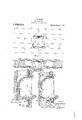
- Figure 1 is a front elevation of the improved receptacle in place in a wall
- Fig. 2 shows the wall in section and the receptacle in plan
- Fig. 3 is a vertical sectional view, on a larger scale, of the receptacle and the wall,
- Fi -4 is a view similar to Fig. 3, but showing the flange of the receptacle overlapping the surface of the wall.
- the receptacle is formed of an integral piece of material such as china in the shape of a boxlike structure. It includes a bottom wall a, a back wall 6, a top wall a and two substantially planiform side walls d, an external continuous flange or rim e arranged in a vertical plane at the front or open side of the receptacle, and a lip f forming a forward extension of the bottom wall a; v
- Each of the several walls a, b, c and d is of substantially uniform'thickness throughout. 1
- The'two side walls d stand in vertical planes parallel with each other and are flat, substantially from top to bottom.
- the bottom wall a with the extension.
- the under slde of the wall a is preferably flat for a sultable distance back from the flange e.
- the back wall 6 is as to its lower part flat and stands in a vertical lane.
- the top wall a is at 1ts forward portionflat and horizontal, but as for the rearward portion thereof and the upper portion of the wall b, they follow a concave curve of a relatively large radius, as at c.
- the front edges of the walls 0 and'd are in a vertlcal plane; the lip f projects for ward beyond this plane.
- the receptacle is formed with two upper and two lower rightangular proect1on s 9,: each upper and lower project10n 9 1s ahned with or forms a continuation of one of the side walls d.
- the receptacle consists of theparallel upright rectangular sides dg, a concave-convex recelver-wall, a, b and 0, opening laterally and ]01l11ng said sides and having its top and back portions merging together in a curve of relatively large radius, .and'a pro1ectmg frontal flan e or rim extending around the margins 0 said sides and receiver-wall, the bottom of the receiver-wall preferably projecting beyond the frontal flange or run.
- the receptacle may be set in the wall structure either as shown in Fig. 3, where the front surface of its flange e is flush with the surface of the tiling h or the like superficial portion of the wall, or, as shown in Fig. 4, where the flange e overlaps the tiling k. In either case, it is secured in position by mortar or the like a laced around that portionthereof which f dr a more or less distance back of the flange e is rectangular in a vertical section arallel with the out plane of the receptac e; its generally square shape and its flange respectively assist the mason in leveling up the receptacle and as a gage intruing the same in proper relation to the wall surface.
- the angular projections g aflord rests or supports for the receptacle at the back thereof, they being shown in the present case as abutting the inside of the mortar or and its back surother material forming the part of the wall some o/pposed surface, such as that of the It will be apparent that the interior of the receptacle 1s so formed as to permit the same to e readily cleaned; the difliculty of keeging the top of the inside clean is avoided y forming the top and back walls so that they merge into each other in a curve of relatively large radius, and the dished or shallow concave form of the bottom wall and the absence of anfgles in the bottom portion of the inside 0 the receptacle makes it possible to readily remove the soap drainy providin the projecting lip f, the bottom wall a ords ample supportingrsurface for the soa without making the ontto-rear depth 0 the receptacle so great that it may not be set in a relatively thin wall
- a wall receptacle including, integrally formed, a pair of tially rectangular si vex receiver-wall open terally and 'o' said sides and forming top, bottom arid bacE' walls and having its to and back wall portions in art substanti y flush with the top and bac edges of said sides, respectively, and thereupon merging into each other in a curve of relatively large radius.
- a rece taclefor to at articles including, integra y formed, a box-like structure having top, back, bottom and two side walls and be open for nearly-its full height and wid at the front, thebottom having a horizontal under bearing surface and being closed and shallow-concave and said receptacle having its back and top walls mergingtin a curve of relatively large radius, and a ontalvertical flan having said bottom, top and two side we merging thereinto.
- a race tacle for toilet articles including, integr y formed, a pair of aced upright substantially rectangular si es, and concavo-convex receiver-wall open laterally and joining said sides and forming top, bottom and back walls and having its top andlcfl back wall portions in part substantially flush with the top and back edges of said sides, rescplectively, and thereupon merging into ea other in a curve of relatively large radius.
Landscapes
- Detergent Compositions (AREA)
Description
S. D. BAKER.
SOAP RECEPTACLE.
APPLICATION mso APR-3,1915.
Patented Sept. 4, 1917.
- SOAP-BECEPTACLE.
1,239,076. I Specification of Letters Patent.
To all whom may concern:
, Be it known that I, STEPHEN D. BAKER, a citizen of the United States, residing at New York city,'in the county of New York and State of New York, have mvented certain new and useful Improvements in Soap-Receptacles, of which the following is a specification.
My object is to provide a receptacle for soap and the like toilet articles that'may be built into the wall of a bath room as a permanent fixture and which shall'be so constructed as to facilitate the masons work in properly setting it in the wall, afl'orda neat and attractive appearance when in place, be capable of being readily cleaned, and have ample supporting surface for the soap or other article without requiring its depth to be such that it may not be set in walls or partitions of even the modern relatively thin construction.
In the accompanying drawing,
Figure 1 is a front elevation of the improved receptacle in place in a wall;
Fig. 2 shows the wall in section and the receptacle in plan;
Fig. 3 is a vertical sectional view, on a larger scale, of the receptacle and the wall,
' the front face of the receptacle being shown in this case flush with the wall surface; and,
Fi -4 is a view similar to Fig. 3, but showing the flange of the receptacle overlapping the surface of the wall.
Describing in detail the preferred form of the invention shown in the drawing: The receptacle is formed of an integral piece of material such as china in the shape of a boxlike structure. It includes a bottom wall a, a back wall 6, a top wall a and two substantially planiform side walls d, an external continuous flange or rim e arranged in a vertical plane at the front or open side of the receptacle, and a lip f forming a forward extension of the bottom wall a; v
- Each of the several walls a, b, c and d is of substantially uniform'thickness throughout. 1
The'two side walls d stand in vertical planes parallel with each other and are flat, substantially from top to bottom.
The bottom wall a with the extension.
Patente @ept. a, ram.
Application med April 1915. Serial No. 19,026.
tion of the lip f to the rear of the wall a. The under slde of the wall a is preferably flat for a sultable distance back from the flange e.
The back wall 6 is as to its lower part flat and stands in a vertical lane.
The top wall a is at 1ts forward portionflat and horizontal, but as for the rearward portion thereof and the upper portion of the wall b, they follow a concave curve of a relatively large radius, as at c. The front edges of the walls 0 and'd are in a vertlcal plane; the lip f projects for ward beyond this plane. Surrounding the walls a, c and d and with 1ts front face flush with the plane last referred to IS the continuous flange e; this is square in front elevation, face is formed as a channel e extending contlnuously of said flange.
At the back the receptacle is formed with two upper and two lower rightangular proect1on s 9,: each upper and lower project10n 9 1s ahned with or forms a continuation of one of the side walls d. Thus, in effect, the receptacle consists of theparallel upright rectangular sides dg, a concave-convex recelver-wall, a, b and 0, opening laterally and ]01l11ng said sides and having its top and back portions merging together in a curve of relatively large radius, .and'a pro1ectmg frontal flan e or rim extending around the margins 0 said sides and receiver-wall, the bottom of the receiver-wall preferably projecting beyond the frontal flange or run.
The receptacle may be set in the wall structure either as shown in Fig. 3, where the front surface of its flange e is flush with the surface of the tiling h or the like superficial portion of the wall, or, as shown in Fig. 4, where the flange e overlaps the tiling k. In either case, it is secured in position by mortar or the like a laced around that portionthereof which f dr a more or less distance back of the flange e is rectangular in a vertical section arallel with the out plane of the receptac e; its generally square shape and its flange respectively assist the mason in leveling up the receptacle and as a gage intruing the same in proper relation to the wall surface.
The angular projections g aflord rests or supports for the receptacle at the back thereof, they being shown in the present case as abutting the inside of the mortar or and its back surother material forming the part of the wall some o/pposed surface, such as that of the It will be apparent that the interior of the receptacle 1s so formed as to permit the same to e readily cleaned; the difliculty of keeging the top of the inside clean is avoided y forming the top and back walls so that they merge into each other in a curve of relatively large radius, and the dished or shallow concave form of the bottom wall and the absence of anfgles in the bottom portion of the inside 0 the receptacle makes it possible to readily remove the soap drainy providin the projecting lip f, the bottom wall a ords ample supportingrsurface for the soa without making the ontto-rear depth 0 the receptacle so great that it may not be set in a relatively thin wall, if not in the manner shown in Fig. 3, where its flange is flush with that of the wall surface, at least in the manner shown in Fig. 4, where its flangf overlaps.
I do not wi to be limited to a receptacle for toilet articles in the exact form herein described and shown, nor specifically to be used as a fixture, what I clann being 1. A wall receptacle including, integrally formed, a pair of tially rectangular si vex receiver-wall open terally and 'o' said sides and forming top, bottom arid bacE' walls and having its to and back wall portions in art substanti y flush with the top and bac edges of said sides, respectively, and thereupon merging into each other in a curve of relatively large radius.
2. A rece taclefor to at articles including, integra y formed, a box-like structure having top, back, bottom and two side walls and be open for nearly-its full height and wid at the front, thebottom having a horizontal under bearing surface and being closed and shallow-concave and said receptacle having its back and top walls mergingtin a curve of relatively large radius, and a ontalvertical flan having said bottom, top and two side we merging thereinto.
3. A race tacle for toilet articles including, integr y formed, a pair of aced upright substantially rectangular si es, and concavo-convex receiver-wall open laterally and joining said sides and forming top, bottom and back walls and having its top andlcfl back wall portions in part substantially flush with the top and back edges of said sides, rescplectively, and thereupon merging into ea other in a curve of relatively large radius. e
In testimony whereof I afiix my signature.
STEPHEN D. BAKER.
Priority Applications (1)
| Application Number | Priority Date | Filing Date | Title |
|---|---|---|---|
| US1902615A US1239076A (en) | 1915-04-08 | 1915-04-08 | Soap-receptacle. |
Applications Claiming Priority (1)
| Application Number | Priority Date | Filing Date | Title |
|---|---|---|---|
| US1902615A US1239076A (en) | 1915-04-08 | 1915-04-08 | Soap-receptacle. |
Publications (1)
| Publication Number | Publication Date |
|---|---|
| US1239076A true US1239076A (en) | 1917-09-04 |
Family
ID=3306891
Family Applications (1)
| Application Number | Title | Priority Date | Filing Date |
|---|---|---|---|
| US1902615A Expired - Lifetime US1239076A (en) | 1915-04-08 | 1915-04-08 | Soap-receptacle. |
Country Status (1)
| Country | Link |
|---|---|
| US (1) | US1239076A (en) |
Cited By (5)
| Publication number | Priority date | Publication date | Assignee | Title |
|---|---|---|---|---|
| US2577011A (en) * | 1949-03-08 | 1951-12-04 | Hall Mack Company | Bathroom article holder |
| US2857754A (en) * | 1956-01-16 | 1958-10-28 | Albert J Reinert | Tiled wall with fixture secured thereto by fastener |
| US5067286A (en) * | 1989-02-13 | 1991-11-26 | Richer Raymond P | Planter |
| US5241715A (en) * | 1992-01-03 | 1993-09-07 | Duvall William K | Shampoo box for shower enclosure |
| US20060181181A1 (en) * | 2005-02-16 | 2006-08-17 | Helme Calfee | Brush holder |
-
1915
- 1915-04-08 US US1902615A patent/US1239076A/en not_active Expired - Lifetime
Cited By (6)
| Publication number | Priority date | Publication date | Assignee | Title |
|---|---|---|---|---|
| US2577011A (en) * | 1949-03-08 | 1951-12-04 | Hall Mack Company | Bathroom article holder |
| US2857754A (en) * | 1956-01-16 | 1958-10-28 | Albert J Reinert | Tiled wall with fixture secured thereto by fastener |
| US5067286A (en) * | 1989-02-13 | 1991-11-26 | Richer Raymond P | Planter |
| US5241715A (en) * | 1992-01-03 | 1993-09-07 | Duvall William K | Shampoo box for shower enclosure |
| US5307530A (en) * | 1992-01-03 | 1994-05-03 | Duvall William K | Shampoo box for shower enclosure |
| US20060181181A1 (en) * | 2005-02-16 | 2006-08-17 | Helme Calfee | Brush holder |
Similar Documents
| Publication | Publication Date | Title |
|---|---|---|
| US1239076A (en) | Soap-receptacle. | |
| US1436990A (en) | Paper container | |
| US2130196A (en) | Lavatory unit | |
| US4621730A (en) | Aerated soapholder | |
| US809592A (en) | Metallic wall-closet. | |
| US1883496A (en) | Combination floor and scale construction | |
| US2414379A (en) | Toothbrush holder | |
| US3298767A (en) | Drawer | |
| US1193862A (en) | I-babtcis boobaem | |
| US837221A (en) | Table. | |
| US1739622A (en) | Toilet cabinet | |
| US3315686A (en) | Wall-mountable ash receptacle | |
| USD244254S (en) | Wallplate | |
| JPS5910554Y2 (en) | storage container | |
| USD245396S (en) | Wall plate | |
| JPS6345999Y2 (en) | ||
| US1180544A (en) | Display-stand for chinaware, earthenware, glass, and other goods. | |
| US659225A (en) | Display and cell case. | |
| USD243924S (en) | Wall plate | |
| USD50291S (en) | Design for a wall-receptacle for soap and other toilet articles | |
| US2881557A (en) | Soap holder | |
| GB1437475A (en) | Toilet tissue holder | |
| JPH0636771Y2 (en) | Storage box | |
| USD35776S (en) | Design for a dental-instrument cabinet | |
| USD243923S (en) | Wall plate |