US12327182B2 - Optimizations for analog hardware realization of trained neural networks - Google Patents
Optimizations for analog hardware realization of trained neural networks Download PDFInfo
- Publication number
- US12327182B2 US12327182B2 US17/199,373 US202117199373A US12327182B2 US 12327182 B2 US12327182 B2 US 12327182B2 US 202117199373 A US202117199373 A US 202117199373A US 12327182 B2 US12327182 B2 US 12327182B2
- Authority
- US
- United States
- Prior art keywords
- analog
- network
- equivalent
- implementations
- neuron
- Prior art date
- Legal status (The legal status is an assumption and is not a legal conclusion. Google has not performed a legal analysis and makes no representation as to the accuracy of the status listed.)
- Active, expires
Links
Images


Classifications
-
- G—PHYSICS
- G06—COMPUTING OR CALCULATING; COUNTING
- G06N—COMPUTING ARRANGEMENTS BASED ON SPECIFIC COMPUTATIONAL MODELS
- G06N3/00—Computing arrangements based on biological models
- G06N3/02—Neural networks
- G06N3/08—Learning methods
- G06N3/082—Learning methods modifying the architecture, e.g. adding, deleting or silencing nodes or connections
-
- G—PHYSICS
- G06—COMPUTING OR CALCULATING; COUNTING
- G06F—ELECTRIC DIGITAL DATA PROCESSING
- G06F1/00—Details not covered by groups G06F3/00 - G06F13/00 and G06F21/00
- G06F1/26—Power supply means, e.g. regulation thereof
- G06F1/32—Means for saving power
- G06F1/3203—Power management, i.e. event-based initiation of a power-saving mode
- G06F1/3206—Monitoring of events, devices or parameters that trigger a change in power modality
-
- G—PHYSICS
- G06—COMPUTING OR CALCULATING; COUNTING
- G06F—ELECTRIC DIGITAL DATA PROCESSING
- G06F1/00—Details not covered by groups G06F3/00 - G06F13/00 and G06F21/00
- G06F1/26—Power supply means, e.g. regulation thereof
- G06F1/32—Means for saving power
- G06F1/3203—Power management, i.e. event-based initiation of a power-saving mode
- G06F1/3234—Power saving characterised by the action undertaken
- G06F1/3287—Power saving characterised by the action undertaken by switching off individual functional units in the computer system
-
- G—PHYSICS
- G06—COMPUTING OR CALCULATING; COUNTING
- G06F—ELECTRIC DIGITAL DATA PROCESSING
- G06F30/00—Computer-aided design [CAD]
- G06F30/30—Circuit design
- G06F30/39—Circuit design at the physical level
-
- G—PHYSICS
- G06—COMPUTING OR CALCULATING; COUNTING
- G06N—COMPUTING ARRANGEMENTS BASED ON SPECIFIC COMPUTATIONAL MODELS
- G06N3/00—Computing arrangements based on biological models
- G06N3/02—Neural networks
- G06N3/04—Architecture, e.g. interconnection topology
- G06N3/044—Recurrent networks, e.g. Hopfield networks
- G06N3/0442—Recurrent networks, e.g. Hopfield networks characterised by memory or gating, e.g. long short-term memory [LSTM] or gated recurrent units [GRU]
-
- G—PHYSICS
- G06—COMPUTING OR CALCULATING; COUNTING
- G06N—COMPUTING ARRANGEMENTS BASED ON SPECIFIC COMPUTATIONAL MODELS
- G06N3/00—Computing arrangements based on biological models
- G06N3/02—Neural networks
- G06N3/04—Architecture, e.g. interconnection topology
- G06N3/045—Combinations of networks
-
- G—PHYSICS
- G06—COMPUTING OR CALCULATING; COUNTING
- G06N—COMPUTING ARRANGEMENTS BASED ON SPECIFIC COMPUTATIONAL MODELS
- G06N3/00—Computing arrangements based on biological models
- G06N3/02—Neural networks
- G06N3/04—Architecture, e.g. interconnection topology
- G06N3/0464—Convolutional networks [CNN, ConvNet]
-
- G—PHYSICS
- G06—COMPUTING OR CALCULATING; COUNTING
- G06N—COMPUTING ARRANGEMENTS BASED ON SPECIFIC COMPUTATIONAL MODELS
- G06N3/00—Computing arrangements based on biological models
- G06N3/02—Neural networks
- G06N3/04—Architecture, e.g. interconnection topology
- G06N3/049—Temporal neural networks, e.g. delay elements, oscillating neurons or pulsed inputs
-
- G—PHYSICS
- G06—COMPUTING OR CALCULATING; COUNTING
- G06N—COMPUTING ARRANGEMENTS BASED ON SPECIFIC COMPUTATIONAL MODELS
- G06N3/00—Computing arrangements based on biological models
- G06N3/02—Neural networks
- G06N3/04—Architecture, e.g. interconnection topology
- G06N3/0495—Quantised networks; Sparse networks; Compressed networks
-
- G—PHYSICS
- G06—COMPUTING OR CALCULATING; COUNTING
- G06N—COMPUTING ARRANGEMENTS BASED ON SPECIFIC COMPUTATIONAL MODELS
- G06N3/00—Computing arrangements based on biological models
- G06N3/02—Neural networks
- G06N3/04—Architecture, e.g. interconnection topology
- G06N3/0499—Feedforward networks
-
- G—PHYSICS
- G06—COMPUTING OR CALCULATING; COUNTING
- G06N—COMPUTING ARRANGEMENTS BASED ON SPECIFIC COMPUTATIONAL MODELS
- G06N3/00—Computing arrangements based on biological models
- G06N3/02—Neural networks
- G06N3/06—Physical realisation, i.e. hardware implementation of neural networks, neurons or parts of neurons
- G06N3/063—Physical realisation, i.e. hardware implementation of neural networks, neurons or parts of neurons using electronic means
- G06N3/065—Analogue means
-
- G—PHYSICS
- G06—COMPUTING OR CALCULATING; COUNTING
- G06N—COMPUTING ARRANGEMENTS BASED ON SPECIFIC COMPUTATIONAL MODELS
- G06N3/00—Computing arrangements based on biological models
- G06N3/02—Neural networks
- G06N3/08—Learning methods
- G06N3/09—Supervised learning
-
- G—PHYSICS
- G06—COMPUTING OR CALCULATING; COUNTING
- G06N—COMPUTING ARRANGEMENTS BASED ON SPECIFIC COMPUTATIONAL MODELS
- G06N5/00—Computing arrangements using knowledge-based models
- G06N5/04—Inference or reasoning models
-
- G—PHYSICS
- G06—COMPUTING OR CALCULATING; COUNTING
- G06N—COMPUTING ARRANGEMENTS BASED ON SPECIFIC COMPUTATIONAL MODELS
- G06N3/00—Computing arrangements based on biological models
- G06N3/02—Neural networks
- G06N3/04—Architecture, e.g. interconnection topology
- G06N3/048—Activation functions
Definitions
- the disclosed implementations relate generally to neural networks, and more specifically to systems and methods for hardware realization of neural networks.
- memristor-based architectures that use cross-bar technology remain impractical for manufacturing recurrent and feed-forward neural networks.
- memristor-based cross-bars have a number of disadvantages, including high latency and leakage of currents during operation, that make them impractical.
- there are reliability issues in manufacturing memristor-based cross-bars especially when neural networks have both negative and positive weights.
- memristor-based cross-bars cannot be used for simultaneous propagation of different signals, which in turn complicates summation of signals, when neurons are represented by operational amplifiers.
- memristor-based analog integrated circuits have a number of limitations, such as a small number of resistive states, first cycle problem when forming memristors, complexity with channel formation when training the memristors, unpredictable dependency on dimensions of the memristors, slow operations of memristors, and drift of state of resistance.
- a trained neural network is used for specific inferencing tasks, such as classification. Once a neural network is trained, a hardware equivalent is manufactured. When the neural network is retrained, the hardware manufacturing process is repeated, driving up costs.
- some reconfigurable hardware solutions exist, such hardware cannot be easily mass produced, and cost a lot more (e.g., cost 5 times more) than hardware that is not reconfigurable.
- edge environments such as smart-home applications, do not require re-programmability as such. For example, 85% of all applications of neural networks do not require any retraining during operation, so on-chip learning is not that useful.
- edge applications include noisy environments, that can cause reprogrammable hardware to become unreliable.
- Analog circuits that model trained neural networks and manufactured according to the techniques described herein, can provide improved performance per watt advantages, can be useful in implementing hardware solutions in edge environments, and can tackle a variety of applications, such as drone navigation and autonomous cars.
- the cost advantages provided by the proposed manufacturing methods and/or analog network architectures are even more pronounced with larger neural networks.
- analog hardware implementations of neural networks provide improved parallelism and neuromorphism.
- neuromorphic analog components are not sensitive to noise and temperature changes, when compared to digital counterparts.
- Chips manufactured according to the techniques described herein provide order of magnitude improvements over conventional systems in size, power, and performance, and are ideal for edge environments, including for retraining purposes.
- Such analog neuromorphic chips can be used to implement edge computing applications or in Internet-of-Things (IoT) environments.
- IoT Internet-of-Things Due to the analog hardware, initial processing (e.g., formation of descriptors for image recognition), that can consume over 80-90% of power, can be moved on chip, thereby decreasing energy consumption and network load that can open new markets for applications.
- CMOS complementary metal-oxide-semiconductor
- CMOS complementary metal-oxide-semiconductor
- Various other video processing applications include road sign recognition for automobiles, camera-based true depth and/or simultaneous localization and mapping for robots, room access control without server connection, and always-on solutions for security and healthcare.
- Such chips can be used for data processing from radars and lidars, and for low-level data fusion.
- Such techniques can be used to implement battery management features for large battery packs, sound/voice processing without connection to data centers, voice recognition on mobile devices, wake up speech instructions for IoT sensors, translators that translate one language to another, large sensors arrays of IoT with low signal intensity, and/or configurable process control with hundreds of sensors.
- Neuromorphic analog chips can be mass produced after standard software-based neural network simulations/training, according to some implementations.
- a client's neural network can be easily ported, regardless of the structure of the neural network, with customized chip design and production.
- a library of ready to make on-chip solutions are provided, according to some implementations. Such solutions require only training, one lithographic mask change, following which chips can be mass produced. For example, during chip production, only part of the lithography masks need to be changed.
- the process begins with a trained neural network that is first converted into a transformed network comprised of standard elements. Operation of the transformed network are simulated using software with known models representing the standard elements. The software simulation is used to determine the individual resistance values for each of the resistors in the transformed network. Lithography masks are laid out based on the arrangement of the standard elements in the transformed network. Each of the standard elements are laid out in the masks using an existing library of circuits corresponding to the standard elements to simplify and speed up the process.
- the resistors are laid out in one or more masks separate from the masks including the other elements (e.g., operational amplifiers) in the transformed network.
- the other elements e.g., operational amplifiers
- the lithography masks are then sent to a fab for manufacturing the analog neuromorphic integrated circuit.
- a method for hardware realization of neural networks, according to some implementations.
- the method incudes obtaining a neural network topology and weights of a trained neural network.
- the method also includes transforming the neural network topology to an equivalent analog network of analog components.
- the method also includes computing a weight matrix for the equivalent analog network based on the weights of the trained neural network. Each element of the weight matrix represents a respective connection between analog components of the equivalent analog network.
- the method also includes generating a schematic model for implementing the equivalent analog network based on the weight matrix, including selecting component values for the analog components.
- generating the schematic model includes generating a resistance matrix for the weight matrix.
- Each element of the resistance matrix corresponds to a respective weight of the weight matrix and represents a resistance value.
- the method further includes obtaining new weights for the trained neural network, computing a new weight matrix for the equivalent analog network based on the new weights, and generating a new resistance matrix for the new weight matrix.
- the neural network topology includes one or more layers of neurons, each layer of neurons computing respective outputs based on a respective mathematical function, and transforming the neural network topology to the equivalent analog network of analog components includes: for each layer of the one or more layers of neurons: (i) identifying one or more function blocks, based on the respective mathematical function, for the respective layer.
- Each function block has a respective schematic implementation with block outputs that conform to outputs of a respective mathematical function; and (ii) generating a respective multilayer network of analog neurons based on arranging the one or more function blocks.
- Each analog neuron implements a respective function of the one or more function blocks, and each analog neuron of a first layer of the multilayer network is connected to one or more analog neurons of a second layer of the multilayer network.
- ReLU Rectified Linear Unit (ReLU) activation function or a similar activation function, V i represents an i-th input, w i represents a weight corresponding to the i-th input, and bias represents a bias value, and ⁇ is a summation operator;
- a signal multiplier block with a block output V out coeff ⁇ V i ⁇ V j .
- V i represents an i-th input and V j represents a j-th input, and coeff is a predetermined coefficient;
- V out A 1 + e - B ⁇ V .
- V represents an input, and A and B are predetermined coefficient values of the sigmoid activation block;
- a hyperbolic tangent activation block with a block output V out A*tanh(B*V in ).
- V in represents an input, and A and B are predetermined coefficient values;
- a signal delay block with a block output U(t) V(t ⁇ dt).
- t represents a current time-period
- V(t ⁇ dt) represents an output of the signal delay block for a preceding time period t ⁇ dt
- dt is a delay value.
- identifying the one or more function blocks includes selecting the one or more function blocks based on a type of the respective layer.
- the neural network topology includes one or more layers of neurons, each layer of neurons computing respective outputs based on a respective mathematical function, and transforming the neural network topology to the equivalent analog network of analog components includes: (i) decomposing a first layer of the neural network topology to a plurality of sub-layers, including decomposing a mathematical function corresponding to the first layer to obtain one or more intermediate mathematical functions.
- Each sub-layer implements an intermediate mathematical function; and (ii) for each sub-layer of the first layer of the neural network topology: (a) selecting one or more sub-function blocks, based on a respective intermediate mathematical function, for the respective sub-layer; and (b) generating a respective multilayer analog sub-network of analog neurons based on arranging the one or more sub-function blocks.
- Each analog neuron implements a respective function of the one or more sub-function blocks, and each analog neuron of a first layer of the multilayer analog sub-network is connected to one or more analog neurons of a second layer of the multilayer analog sub-network.
- the mathematical function corresponding to the first layer includes one or more weights
- decomposing the mathematical function includes adjusting the one or more weights such that combining the one or more intermediate functions results in the mathematical function.
- the method further includes: (i) generating equivalent digital network of digital components for one or more output layers of the neural network topology; and (ii) connecting output of one or more layers of the equivalent analog network to the equivalent digital network of digital components.
- the analog components include a plurality of operational amplifiers and a plurality of resistors, each operational amplifier represents an analog neuron of the equivalent analog network, and each resistor represents a connection between two analog neurons.
- selecting component values of the analog components includes performing a gradient descent method to identify possible resistance values for the plurality of resistors.
- the neural network topology includes one or more GRU or LSTM neurons
- transforming the neural network topology includes generating one or more signal delay blocks for each recurrent connection of the one or more GRU or LSTM neurons.
- the one or more signal delay blocks are activated at a frequency that matches a predetermined input signal frequency for the neural network topology.
- the neural network topology includes one or more layers of neurons that perform unlimited activation functions
- transforming the neural network topology includes applying one or more transformations selected from the group consisting of: (i) replacing the unlimited activation functions with limited activation; and (ii) adjusting connections or weights of the equivalent analog network such that, for predetermined one or more inputs, difference in output between the trained neural network and the equivalent analog network is minimized.
- the method further includes generating one or more lithographic masks for fabricating a circuit implementing the equivalent analog network of analog components based on the resistance matrix.
- the method further includes: (i) obtaining new weights for the trained neural network; (ii) computing a new weight matrix for the equivalent analog network based on the new weights; (iii) generating a new resistance matrix for the new weight matrix; and (iv) generating a new lithographic mask for fabricating the circuit implementing the equivalent analog network of analog components based on the new resistance matrix.
- the trained neural network is trained using software simulations to generate the weights.
- a method for hardware realization of neural networks includes obtaining a neural network topology and weights of a trained neural network.
- the method also includes calculating one or more connection constraints based on analog integrated circuit (IC) design constraints.
- the method also includes transforming the neural network topology to an equivalent sparsely connected network of analog components satisfying the one or more connection constraints.
- the method also includes computing a weight matrix for the equivalent sparsely connected network based on the weights of the trained neural network. Each element of the weight matrix represents a respective connection between analog components of the equivalent sparsely connected network.
- transforming the neural network topology to the equivalent sparsely connected network of analog components includes deriving a possible input connection degree N i and output connection degree N o , according to the one or more connection constraints.
- the neural network topology includes at least one densely connected layer with K inputs and L outputs and a weight matrix U.
- transforming the at least one densely connected layer includes constructing the equivalent sparsely connected network with K inputs, L outputs, and ⁇ log N i K ⁇ + ⁇ log N o L ⁇ 1 layers, such that input connection degree does not exceed N i , and output connection degree does not exceed N o .
- the neural network topology includes at least one densely connected layer with K inputs and L outputs and a weight matrix U.
- transforming the at least one densely connected layer includes constructing the equivalent sparsely connected network with K inputs, L outputs, and M ⁇ max( ⁇ log N i L ⁇ , ⁇ log N o K ⁇ ) layers.
- Each layer m is represented by a corresponding weight matrix U m , where absent connections are represented with zeros, such that input connection degree does not exceed N i , and output connection degree does not exceed N o .
- the neural network topology includes a single sparsely connected layer with K inputs and L outputs, a maximum input connection degree of P i , a maximum output connection degree of P o , and a weight matrix of U, where absent connections are represented with zeros.
- transforming the single sparsely connected layer includes constructing the equivalent sparsely connected network with K inputs, L outputs, M ⁇ max( ⁇ log N i P i ⁇ , ⁇ log N o P o ⁇ ) layers, each layer m represented by a corresponding weight matrix U m , where absent connections are represented with zeros, such that input connection degree does not exceed N i , and output connection degree does not exceed N o .
- the neural network topology includes a convolutional layer with K inputs and L outputs.
- transforming the neural network topology to the equivalent sparsely connected network of analog components includes decomposing the convolutional layer into a single sparsely connected layer with K inputs, L outputs, a maximum input connection degree of P i , and a maximum output connection degree of P o .
- generating a schematic model for implementing the equivalent sparsely connected network utilizing the weight matrix generating a schematic model for implementing the equivalent sparsely connected network utilizing the weight matrix.
- the neural network topology includes a recurrent neural layer.
- transforming the neural network topology to the equivalent sparsely connected network of analog components includes transforming the recurrent neural layer into one or more densely or sparsely connected layers with signal delay connections.
- the neural network topology includes a recurrent neural layer.
- transforming the neural network topology to the equivalent sparsely connected network of analog components includes decomposing the recurrent neural layer into several layers, where at least one of the layers is equivalent to a densely or sparsely connected layer with K inputs and L output and a weight matrix U, where absent connections are represented with zeros.
- the neural network topology includes K inputs, a weight vector U ⁇ R K , and a single layer perceptron with a calculation neuron with an activation function F.
- the equivalent sparsely connected network includes respective one or more analog neurons in each layer of them layers, each analog neuron of first m ⁇ 1 layers implements identity transform, and an analog neuron of last layer implements the activation function F of the calculation neuron of the single layer perceptron.
- computing the weight matrix for the equivalent sparsely connected network includes calculating a weight vector W for connections of the equivalent sparsely connected network by solving a system of equations based on the weight vector U.
- the system of equations includes K equations with S variables, and S is computed using the equation
- the neural network topology includes K inputs, a single layer perceptron with L calculation neurons, and a weight matrix V that includes a row of weights for each calculation neuron of the L calculation neurons.
- Each single layer perceptron network includes a respective calculation neuron of the L calculation neurons; (iv) for each single layer perceptron network of the L single layer perceptron networks: (a) constructing a respective equivalent pyramid-like sub-network for the respective single layer perceptron network with the K inputs, the m layers and the connection degree N.
- the equivalent pyramid-like sub-network includes one or more respective analog neurons in each layer of the m layers, each analog neuron of first m ⁇ 1 layers implements identity transform, and an analog neuron of last layer implements the activation function of the respective calculation neuron corresponding to the respective single layer perceptron; and (b) constructing the equivalent sparsely connected network by concatenating each equivalent pyramid-like sub-network including concatenating an input of each equivalent pyramid-like sub-network for the L single layer perceptron networks to form an input vector with L*K inputs.
- the system of equations includes K equations with S variables, and S is computed using the equation
- the neural network topology includes K inputs, a multi-layer perceptron with S layers, each layer i of the S layers includes a corresponding set of calculation neurons L i and corresponding weight matrices V i that includes a row of weights for each calculation neuron of the L i calculation neurons.
- the equivalent pyramid-like sub-network includes one or more respective analog neurons in each layer of the m layers, each analog neuron of first m ⁇ 1 layers implements identity transform, and an analog neuron of last layer implements the activation function of the respective calculation neuron corresponding to the respective single layer perceptron network; and (iv) constructing the equivalent sparsely connected network by concatenating each equivalent pyramid-like sub-network including concatenating input of each equivalent pyramid-like sub-network for the Q single layer perceptron networks to form an input vector with Q*K i,j inputs.
- the system of equations includes K i,j equations with S variables, and S is computed using the equation
- the neural network topology includes a Convolutional Neural Network (CNN) with K inputs, S layers, each layer i of the S layers includes a corresponding set of calculation neurons L i and corresponding weight matrices V i that includes a row of weights for each calculation neuron of the L i calculation neurons.
- CNN Convolutional Neural Network
- the equivalent pyramid-like sub-network includes one or more respective analog neurons in each layer of the m layers, each analog neuron of first m ⁇ 1 layers implements identity transform, and an analog neuron of last layer implements the activation function of the respective calculation neuron corresponding to the respective single layer perceptron network; and (iv) constructing the equivalent sparsely connected network by concatenating each equivalent pyramid-like sub-network including concatenating input of each equivalent pyramid-like sub-network for the Q single layer perceptron networks to form an input vector with Q*K i,j inputs.
- the system of equations includes K i,j equations with S variables, and S is computed using the equation
- transforming the neural network topology to the equivalent sparsely connected network of analog components includes performing a trapezium transformation that includes: (i) deriving a possible input connection degree N I >1 and a possible output connection degree N O >1, according to the one or more connection constraints; (ii) in accordance with a determination that K ⁇ L ⁇ L ⁇ N I +K ⁇ N O , constructing a three-layered analog network that includes a layer LA p with K analog neurons performing identity activation function, a layer LA h with
- each analog neuron in the layer LA p has N O outputs
- each analog neuron in the layer LA h has not more than N I inputs and N O outputs
- each analog neuron in the layer LA o has N I inputs.
- the sparse weight matrix W o ⁇ R K ⁇ M represents connections between the layers LA p and LA h
- the sparse weight matrix W h ⁇ R M ⁇ L represents connections between the layers LA h and LA o .
- performing the trapezium transformation further includes: in accordance with a determination that K ⁇ L ⁇ L ⁇ N I +K ⁇ N O : (i) splitting the layer L p to obtain a sub-layer L p1 with K′ neurons and a sub-layer L p2 with (K ⁇ K′) neurons such that K′ ⁇ L ⁇ L ⁇ N I +K′ ⁇ N O ; (ii) for the sub-layer L p1 with K′ neurons, performing the constructing, and generating steps; and (iii) for the sub-layer L p2 with K ⁇ K′ neurons, recursively performing the splitting, constructing, and generating steps.
- the neural network topology includes a multilayer perceptron network.
- the method further includes, for each pair of consecutive layers of the multilayer perceptron network, iteratively performing the trapezium transformation and computing the weight matrix for the equivalent sparsely connected network.
- the neural network topology includes a recurrent neural network (RNN) that includes (i) a calculation of linear combination for two fully connected layers, (ii) element-wise addition, and (iii) a non-linear function calculation.
- RNN recurrent neural network
- the method further includes performing the trapezium transformation and computing the weight matrix for the equivalent sparsely connected network, for (i) the two fully connected layers, and (ii) the non-linear function calculation.
- the neural network topology includes a long short-term memory (LSTM) network or a gated recurrent unit (GRU) network that includes (i) a calculation of linear combination for a plurality of fully connected layers, (ii) element-wise addition, (iii) a Hadamard product, and (iv) a plurality of non-linear function calculations.
- the method further includes performing the trapezium transformation and computing the weight matrix for the equivalent sparsely connected network, for (i) the plurality of fully connected layers, and (ii) the plurality of non-linear function calculations.
- the neural network topology includes a convolutional neural network (CNN) that includes (i) a plurality of partially connected layers and (ii) one or more fully-connected layers.
- CNN convolutional neural network
- the method further includes: (i) transforming the plurality of partially connected layers to equivalent fully-connected layers by inserting missing connections with zero weights; and (ii) for each pair of consecutive layers of the equivalent fully-connected layers and the one or more fully-connected layers, iteratively performing the trapezium transformation and computing the weight matrix for the equivalent sparsely connected network.
- the neural network topology includes K inputs, L output neurons, and a weight matrix U ⁇ R L ⁇ K , where R is the set of real numbers, each output neuron performs an activation function F.
- transforming the neural network topology to the equivalent sparsely connected network of analog components includes performing an approximation transformation that includes: (i) deriving a possible input connection degree N I >1 and a possible output connection degree N O >1, according to the one or more connection constraints; (ii) selecting a parameter p from the set ⁇ 0, 1, . . .
- transforming the neural network topology to the equivalent sparsely connected network of analog components includes: for each layer j of the S layers of the multilayer perceptron: (i) constructing a respective pyramid-trapezium network PTNNX j by performing the approximation transformation to a respective single layer perceptron consisting of L j ⁇ 1 inputs, L j output neurons, and a weight matrix U j ; and (ii) constructing the equivalent sparsely connected network by stacking each pyramid trapezium network.
- a method for hardware realization of neural networks, according to some implementations.
- the method includes obtaining a neural network topology and weights of a trained neural network.
- the method also includes transforming the neural network topology to an equivalent analog network of analog components including a plurality of operational amplifiers and a plurality of resistors.
- Each operational amplifier represents an analog neuron of the equivalent analog network, and each resistor represents a connection between two analog neurons.
- the method also includes computing a weight matrix for the equivalent analog network based on the weights of the trained neural network.
- Each element of the weight matrix represents a respective connection.
- the method also includes generating a resistance matrix for the weight matrix.
- Each element of the resistance matrix corresponds to a respective weight of the weight matrix and represents a resistance value.
- generating the resistance matrix for the weight matrix includes: (i) obtaining a predetermined range of possible resistance values ⁇ R min , R max ⁇ and selecting an initial base resistance value R base within the predetermined range; (ii) selecting a limited length set of resistance values, within the predetermined range, that provide most uniform distribution of possible weights
- e ⁇ r ⁇ r ( R + R 1 + R - R 2 ) ⁇ r err + ⁇ w - R + R 1 + R - R 2 ⁇ for all possible values of R 1 and R 2 within the predetermined range of possible resistance values.
- w is the respective element of the weight matrix
- r err is a predetermined relative tolerance value for resistances.
- the predetermined range of possible resistance values includes resistances according to nominal series E24 in the range 100 K ⁇ to 1 M ⁇ .
- R + and R ⁇ are chosen independently for each layer of the equivalent analog network.
- R + and R ⁇ are chosen independently for each analog neuron of the equivalent analog network.
- a first one or more weights of the weight matrix and a first one or more inputs represent one or more connections to a first operational amplifier of the equivalent analog network.
- the method further includes, prior to generating the resistance matrix: (i) modifying the first one or more weights by a first value; and (ii) configuring the first operational amplifier to multiply, by the first value, a linear combination of the first one or more weights and the first one or more inputs, before performing an activation function.
- the method further includes: (i) obtaining a predetermined range of weights; and (ii) updating the weight matrix according to the predetermined range of weights such that the equivalent analog network produces similar output as the trained neural network for same input.
- the trained neural network is trained so that each layer of the neural network topology has quantized weights.
- the method further includes retraining the trained neural network to reduce sensitivity to errors in the weights or the resistance values that cause the equivalent analog network to produce different output compared to the trained neural network.
- the method further includes retraining the trained neural network so as to minimize weight in any layer that are more than mean absolute weight for that layer by larger than a predetermined threshold.
- a method for hardware realization of neural networks, according to some implementations.
- the method includes obtaining a neural network topology and weights of a trained neural network.
- the method also includes transforming the neural network topology to an equivalent analog network of analog components including a plurality of operational amplifiers and a plurality of resistors.
- Each operational amplifier represents an analog neuron of the equivalent analog network, and each resistor represents a connection between two analog neurons.
- the method also includes computing a weight matrix for the equivalent analog network based on the weights of the trained neural network.
- Each element of the weight matrix represents a respective connection.
- the method also includes generating a resistance matrix for the weight matrix.
- Each element of the resistance matrix corresponds to a respective weight of the weight matrix.
- the method also includes pruning the equivalent analog network to reduce number of the plurality of operational amplifiers or the plurality of resistors, based on the resistance matrix, to obtain an optimized analog network of analog components.
- pruning the equivalent analog network includes substituting, with conductors, resistors corresponding to one or more elements of the resistance matrix that have resistance values below a predetermined minimum threshold resistance value.
- pruning the equivalent analog network includes removing one or more connections of the equivalent analog network corresponding to one or more elements of the resistance matrix that are above a predetermined maximum threshold resistance value.
- pruning the equivalent analog network includes removing one or more connections of the equivalent analog network corresponding to one or more elements of the weight matrix that are approximately zero.
- pruning the equivalent analog network further includes removing one or more analog neurons of the equivalent analog network without any input connections.
- pruning the equivalent analog network includes: (i) ranking analog neurons of the equivalent analog network based on detecting use of the analog neurons when making calculations for one or more data sets; (ii) selecting one or more analog neurons of the equivalent analog network based on the ranking; and (iii) removing the one or more analog neurons from the equivalent analog network.
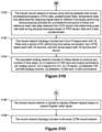
- detecting use of the analog neurons includes: (i) building a model of the equivalent analog network using a modelling software; and (ii) measuring propagation of analog signals by using the model to generate calculations for the one or more data sets.
- detecting use of the analog neurons includes: (i) building a model of the equivalent analog network using a modelling software; and (ii) measuring output signals of the model by using the model to generate calculations for the one or more data sets.
- detecting use of the analog neurons includes: (i) building a model of the equivalent analog network using a modelling software; and (ii) measuring power consumed by the analog neurons by using the model to generate calculations for the one or more data sets.
- the method further includes subsequent to pruning the equivalent analog network, and prior to generating one or more lithographic masks for fabricating a circuit implementing the equivalent analog network, recomputing the weight matrix for the equivalent analog network and updating the resistance matrix based on the recomputed weight matrix.
- the method further includes, for each analog neuron of the equivalent analog network: (i) computing a respective bias value for the respective analog neuron based on the weights of the trained neural network, while computing the weight matrix; (ii) in accordance with a determination that the respective bias value is above a predetermined maximum bias threshold, removing the respective analog neuron from the equivalent analog network; and (iii) in accordance with a determination that the respective bias value is below a predetermined minimum bias threshold, replacing the respective analog neuron with a linear junction in the equivalent analog network.
- the method further includes reducing number of neurons of the equivalent analog network, prior to generating the weight matrix, by increasing number of connections from one or more analog neurons of the equivalent analog network.
- the method further includes pruning the trained neural network to update the neural network topology and the weights of the trained neural network, prior to transforming the neural network topology, using pruning techniques for neural networks, so that the equivalent analog network includes less than a predetermined number of analog components.
- the pruning is performed iteratively taking into account accuracy or a level of match in output between the trained neural network and the equivalent analog network.
- the method further includes, prior to transforming the neural network topology to the equivalent analog network, performing network knowledge extraction.
- an integrated circuit in another aspect, includes an analog network of analog components fabricated by a method that includes: (i) obtaining a neural network topology and weights of a trained neural network; (ii) transforming the neural network topology to an equivalent analog network of analog components including a plurality of operational amplifiers and a plurality of resistors.
- Each operational amplifier represents a respective analog neuron
- each resistor represents a respective connection between a respective first analog neuron and a respective second analog neuron
- computing a weight matrix for the equivalent analog network based on the weights of the trained neural network.
- Each element of the weight matrix represents a respective connection; (iv) generating a resistance matrix for the weight matrix.
- Each element of the resistance matrix corresponds to a respective weight of the weight matrix; (v) generating one or more lithographic masks for fabricating a circuit implementing the equivalent analog network of analog components based on the resistance matrix; and (vi) fabricating the circuit based on the one or more lithographic masks using a lithographic process.
- the integrated circuit further includes one or more digital to analog converters configured to generate analog input for the equivalent analog network of analog components based on one or more digital.
- the integrated circuit further includes an analog signal sampling module configured to process 1-dimensional or 2-dimensional analog inputs with a sampling frequency based on number of inferences of the integrated circuit.
- the integrated circuit further includes a voltage converter module to scale down or scale up analog signals to match operational range of the plurality of operational amplifiers.
- the integrated circuit further includes a tact signal processing module configured to process one or more frames obtained from a CCD camera.
- the trained neural network is a long short-term memory (LSTM) network.
- the integrated circuit further includes one or more clock modules to synchronize signal tacts and to allow time series processing.
- the integrated circuit further includes one or more analog to digital converters configured to generate digital signal based on output of the equivalent analog network of analog components.
- the integrated circuit further includes one or more signal processing modules configured to process 1-dimensional or 2-dimensional analog signals obtained from edge applications.
- the trained neural network is trained, using training datasets containing signals of arrays of gas sensors on different gas mixture, for selective sensing of different gases in a gas mixture containing predetermined amounts of gases to be detected.
- the neural network topology is a 1-Dimensional Deep Convolutional Neural network (1D-DCNN) designed for detecting 3 binary gas components based on measurements by 16 gas sensors, and includes 16 sensor-wise 1-D convolutional blocks, 3 shared or common 1-D convolutional blocks and 3 dense layers.
- the equivalent analog network includes: (i) a maximum of 100 input and output connections per analog neuron, (ii) delay blocks to produce delay by any number of time steps, (iii) a signal limit of 5, (iv) 15 layers, (v) approximately 100,000 analog neurons, and (vi) approximately 4,900,000 connections.
- the trained neural network is trained, using training datasets containing thermal aging time series data for different MOSFETs, for predicting remaining useful life (RUL) of a MOSFET device.
- the neural network topology includes 4 LSTM layers with 64 neurons in each layer, followed by two dense layers with 64 neurons and 1 neuron, respectively.
- the equivalent analog network includes: (i) a maximum of 100 input and output connections per analog neuron, (ii) a signal limit of 5, (iii) 18 layers, (iv) between 3,000 and 3,200 analog neurons, and (v) between 123,000 and 124,000 connections.
- the trained neural network is trained, using training datasets containing time series data including discharge and temperature data during continuous usage of different commercially available Li-Ion batteries, for monitoring state of health (SOH) and state of charge (SOC) of Lithium Ion batteries to use in battery management systems (BMS).
- the neural network topology includes an input layer, 2 LSTM layers with 64 neurons in each layer, followed by an output dense layer with 2 neurons for generating SOC and SOH values.
- the equivalent analog network includes: (i) a maximum of 100 input and output connections per analog neuron, (ii) a signal limit of 5, (iii) 9 layers, (iv) between 1,200 and 1,300 analog neurons, and (v) between 51,000 and 52,000 connections.
- the trained neural network is trained, using training datasets containing time series data including discharge and temperature data during continuous usage of different commercially available Li-Ion batteries, for monitoring state of health (SOH) of Lithium Ion batteries to use in battery management systems (BMS).
- the neural network topology includes an input layer with 18 neurons, a simple recurrent layer with 100 neurons, and a dense layer with 1 neuron.
- the equivalent analog network includes: (i) a maximum of 100 input and output connections per analog neuron, (ii) a signal limit of 5, (iii) 4 layers, (iv) between 200 and 300 analog neurons, and (v) between 2,200 and 2,400 connections.
- the trained neural network is trained, using training datasets containing speech commands, for identifying voice commands.
- the neural network topology is a Depthwise Separable Convolutional Neural Network (DS-CNN) layer with 1 neuron.
- the equivalent analog network includes: (i) a maximum of 100 input and output connections per analog neuron, (ii) a signal limit of 5, (iii) 13 layers, (iv) approximately 72,000 analog neurons, and (v) approximately 2.6 million connections.
- the trained neural network is trained, using training datasets containing photoplethysmography (PPG) data, accelerometer data, temperature data, and electrodermal response signal data for different individuals performing various physical activities for a predetermined period of times and reference heart rate data obtained from ECG sensor, for determining pulse rate during physical exercises based on PPG sensor data and 3-axis accelerometer data.
- the neural network topology includes two Conv1D layers each with 16 filters and a kernel of 20, performing time series convolution, two LSTM layers each with 16 neurons, and two dense layers with 16 neurons and 1 neuron, respectively.
- the equivalent analog network includes: (i) delay blocks to produce any number of time steps, (ii) a maximum of 100 input and output connections per analog neuron, (iii) a signal limit of 5, (iv) 16 layers, (v) between 700 and 800 analog neurons, and (vi) between 12,000 and 12,500 connections.
- the trained neural network is trained to classify different objects based on pulsed Doppler radar signal.
- the neural network topology includes multi-scale LSTM neural network.
- the trained neural network is trained to perform human activity type recognition, based on inertial sensor data.
- the neural network topology includes three channel-wise convolutional networks each with a convolutional layer of 12 filters and a kernel dimension of 64, and each followed by a max pooling layer, and two common dense layers of 1024 neurons and N neurons, respectively, where N is a number of classes.
- the equivalent analog network includes: (i) delay blocks to produce any number of time steps, (ii) a maximum of 100 input and output connections per analog neuron, (iii) an output layer of 10 analog neurons, (iv) signal limit of 5, (v) 10 layers, (vi) between 1,200 and 1,300 analog neurons, and (vi) between 20,000 and 21,000 connections.
- a method for generating libraries for hardware realization of neural networks.
- the method includes obtaining a plurality of neural network topologies, each neural network topology corresponding to a respective neural network.
- the method also incudes transforming each neural network topology to a respective equivalent analog network of analog components.
- the method also includes generating a plurality of lithographic masks for fabricating a plurality of circuits, each circuit implementing a respective equivalent analog network of analog components.
- the method further includes obtaining a new neural network topology and weights of a trained neural network.
- the method also includes selecting one or more lithographic masks from the plurality of lithographic masks based on comparing the new neural network topology to the plurality of neural network topologies.
- the method also includes computing a weight matrix for a new equivalent analog network based on the weights.
- the method also includes generating a resistance matrix for the weight matrix.
- the method also includes generating a new lithographic mask for fabricating a circuit implementing the new equivalent analog network based on the resistance matrix and the one or more lithographic masks.
- the new neural network topology includes a plurality of subnetwork topologies
- selecting the one or more lithographic masks is further based on comparing each subnetwork topology with each network topology of the plurality of network topologies.
- one or more subnetwork topologies of the plurality of subnetwork topologies fails to compare with any network topology of the plurality of network topologies.
- the method further includes: (i) transforming each subnetwork topology of the one or more subnetwork topologies to a respective equivalent analog subnetwork of analog components; and (ii) generating one or more lithographic masks for fabricating one or more circuits, each circuit of the one or more circuits implementing a respective equivalent analog subnetwork of analog components.
- transforming a respective network topology to a respective equivalent analog network includes: (i) decomposing the respective network topology to a plurality of subnetwork topologies; (ii) transforming each subnetwork topology to a respective equivalent analog subnetwork of analog components; and (iii) composing each equivalent analog subnetwork to obtain the respective equivalent analog network.
- decomposing the respective network topology includes identifying one or more layers of the respective network topology as the plurality of subnetwork topologies.
- each circuit is obtained by: (i) generating schematics for a respective equivalent analog network of analog components; and (ii) generating a respective circuit layout design based on the schematics.
- the method further includes combining one or more circuit layout designs prior to generating the plurality of lithographic masks for fabricating the plurality of circuits.
- a method for optimizing energy efficiency of analog neuromorphic circuits, according to some implementations.
- the method includes obtaining an integrated circuit implementing an analog network of analog components including a plurality of operational amplifiers and a plurality of resistors.
- the analog network represents a trained neural network, each operational amplifier represents a respective analog neuron, and each resistor represents a respective connection between a respective first analog neuron and a respective second analog neuron.
- the method also include generating inferences using the integrated circuit for a plurality of test inputs, including simultaneously transferring signals from one layer to a subsequent layer of the analog network.
- the method also includes, while generating inferences using the integrated circuit: (i) determining if a level of signal output of the plurality of operational amplifiers is equilibrated; and (ii) in accordance with a determination that the level of signal output is equilibrated: (a) determining an active set of analog neurons of the analog network influencing signal formation for propagation of signals; and (turning off power for one or more analog neurons of the analog network, distinct from the active set of analog neurons, for a predetermined period of time.
- determining the active set of analog neurons is based on calculating delays of signal propagation through the analog network.
- determining the active set of analog neurons is based on detecting the propagation of signals through the analog network.
- the trained neural network is a feed-forward neural network
- the active set of analog neurons belong to an active layer of the analog network
- turning off power includes turning off power for one or more layers prior to the active layer of the analog network.
- the predetermined period of time is calculated based on simulating propagation of signals through the analog network, accounting for signal delays.
- the trained neural network is a recurrent neural network (RNN), and the analog network further includes one or more analog components other than the plurality of operational amplifiers, and the plurality of resistors.
- the method further includes, in accordance with a determination that the level of signal output is equilibrated, turning off power, for the one or more analog components, for the predetermined period of time.
- the method further includes turning on power for the one or more analog neurons of the analog network after the predetermined period of time.
- determining if the level of signal output of the plurality of operational amplifiers is equilibrated is based on detecting if one or more operational amplifiers of the analog network is outputting more than a predetermined threshold signal level.
- the method further includes repeating the turning off for the predetermined period of time and turning on the active set of analog neurons for the predetermined period of time, while generating the inferences.
- the method further includes: (i) in accordance with a determination that the level of signal output is equilibrated, for each inference cycle: (a) during a first time interval, determining a first layer of analog neurons of the analog network influencing signal formation for propagation of signals; and (b) turning off power for a first one or more analog neurons of the analog network, prior to the first layer, for the predetermined period of time; and (ii) during a second time interval subsequent to the first time interval, turning off power for a second one or more analog neurons including the first layer of analog neurons and the first one or more analog neurons of the analog network, for the predetermined period.
- the one or more analog neurons consist of analog neurons of a first one or more layers of the analog network
- the active set of analog neurons consist of analog neurons of a second layer of the analog network
- the second layer of the analog network is distinct from layers of the first one or more layers.
- a computer system has one or more processors, memory, and a display.
- the one or more programs include instructions for performing any of the methods described herein.
- a non-transitory computer readable storage medium stores one or more programs configured for execution by a computer system having one or more processors, memory, and a display.
- the one or more programs include instructions for performing any of the methods described herein.
- FIG. 1 A is a block diagram of a system for hardware realization of trained neural networks using analog components, according to some implementations.
- FIG. 1 B is a block diagram of an alternative representation of the system of FIG. 1 A for hardware realization of trained neural networks using analog components, according to some implementations.
- FIG. 1 C is a block diagram of another representation of the system of FIG. 1 A for hardware realization of trained neural networks using analog components, according to some implementations.
- FIG. 2 A is a system diagram of a computing device in accordance with some implementations.
- FIG. 2 B shows optional modules of the computing device, according to some implementations.
- FIG. 3 A shows an example process for generating schematic models of analog networks corresponding to trained neural networks, according to some implementations.
- FIG. 3 B shows an example manual prototyping process used for generating a target chip model, according to some implementations.
- FIGS. 4 A, 4 B, and 4 C show examples of neural networks that are transformed to mathematically equivalent analog networks, according to some implementations.
- FIG. 5 shows an example of a math model for a neuron, according to some implementations.
- FIGS. 6 A- 6 C illustrate an example process for analog hardware realization of a neural network for computing an XOR of input values, according to some implementations.
- FIG. 7 shows an example perceptron, according to some implementations.
- FIG. 8 shows an example Pyramid-Neural Network, according to some implementations.
- FIG. 9 shows an example Pyramid Single Neural Network, according to some implementations.
- FIG. 10 shows an example of a transformed neural network, according to some implementations.
- FIGS. 11 A- 11 C show an application of a T-transformation algorithm for a single layer neural network, according to some implementations.
- FIG. 12 shows an example Recurrent Neural Network (RNN), according to some implementations.
- RNN Recurrent Neural Network
- FIG. 13 A is a block diagram of a LSTM neuron, according to some implementations.
- FIG. 13 B shows delay blocks, according to some implementations.
- FIG. 13 C is a neuron schema for a LSTM neuron, according to some implementations.
- FIG. 14 A is a block diagram of a GRU neuron, according to some implementations.
- FIG. 14 B is a neuron schema for a GRU neuron, according to some implementations.
- FIGS. 15 A and 15 B are neuron schema of variants of a single Conv1D filter, according to some implementations.
- FIG. 16 shows an example architecture of a transformed neural network, according to some implementations.
- FIGS. 17 A- 17 C provide example charts illustrating dependency between output error and classification error or weight error, according to some implementations.
- FIG. 18 provides an example scheme of a neuron model used for resistors quantization, according to some implementations.
- FIG. 19 A shows a schematic diagram of an operational amplifier made on CMOS, according to some implementations.
- FIG. 19 B shows a table of description for the example circuit shown in FIG. 19 A , according to some implementations.
- FIGS. 20 A- 20 E show a schematic diagram of a LSTM block, according to some implementations.
- FIG. 20 F shows a table of description for the example circuit shown in FIG. 20 A- 20 D , according to some implementations.
- FIGS. 21 A- 21 I show a schematic diagram of a multiplier block, according to some implementations.
- FIG. 21 J shows a table of description for the schematic shown in FIGS. 21 A- 21 I , according to some implementations.
- FIG. 22 A shows a schematic diagram of a sigmoid neuron, according to some implementations.
- FIG. 22 B shows a table of description for the schematic diagram shown in FIG. 22 A , according to some implementations.
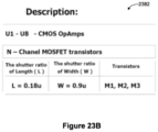
- FIG. 23 A shows a schematic diagram of a hyperbolic tangent function block, according to some implementations.
- FIG. 23 B shows a table of description for the schematic diagram shown in FIG. 23 A , according to some implementations.
- FIGS. 24 A- 24 C show a schematic diagram of a single neuron CMOS operational amplifier, according to some implementations.
- FIG. 24 D shows a table of description for the schematic diagram shown in FIG. 24 A- 24 C , according to some implementations.
- FIGS. 25 A- 25 D show a schematic diagram of a variant of a single neuron CMOS operational amplifiers according to some implementations.
- FIG. 25 E shows a table of description for the schematic diagram shown in FIG. 25 A- 25 D , according to some implementations.
- FIGS. 26 A- 26 K show example weight distribution histograms, according to some implementations.
- FIGS. 27 A- 27 J show a flowchart of a method for hardware realization of neural networks, according to some implementations.
- FIGS. 28 A- 28 S show a flowchart of a method for hardware realization of neural networks according to hardware design constraints, according to some implementations.
- FIGS. 29 A- 29 F show a flowchart of a method for hardware realization of neural networks according to hardware design constraints, according to some implementations.
- FIGS. 30 A- 30 M show a flowchart of a method for hardware realization of neural networks according to hardware design constraints, according to some implementations.
- FIGS. 31 A- 31 Q show a flowchart of a method for fabricating an integrated circuit that includes an analog network of analog components, according to some implementations.
- FIGS. 32 A- 32 E show a flowchart of a method for generating libraries for hardware realization of neural networks, according to some implementations.
- FIGS. 33 A- 33 K show a flowchart of a method for optimizing energy efficiency of analog neuromorphic circuits (that model trained neural networks), according to some implementations.
- FIG. 34 shows a table describing the MobileNet v1 architecture, according to some implementations.
- FIG. 1 A is a block diagram of a system 100 for hardware realization of trained neural networks using analog components, according to some implementations.
- the system includes transforming ( 126 ) trained neural networks 102 to analog neural networks 104 .
- analog integrated circuit constraints 184 constrain ( 146 ) the transformation ( 126 ) to generate the analog neural networks 104 .
- the system derives (calculates or generates) weights 106 for the analog neural networks 104 by a process that is sometimes called weight quantization ( 128 ).
- the analog neural network includes a plurality of analog neuron, each analog neuron represented by an analog component, such as an operational amplifier, and each analog neuron connected to another analog neuron via a connection.
- the connections are represented using resistors that reduce the current flow between two analog neurons.
- the system transforms ( 148 ) the weights 106 to resistance values 112 for the connections.
- the system subsequently generates ( 130 ) one or more schematic models 108 for implementing the analog neural networks 104 based on the weights 106 .
- the system optimizes resistance values 112 (or the weights 106 ) to form optimized analog neural networks 114 which is further used to generate ( 150 ) the schematic models 108 .
- the system generates ( 132 ) lithographic masks 110 for the connections and/or generates ( 136 ) lithographic masks 120 for the analog neurons.
- the system fabricates ( 134 and/or 138 ) analog integrated circuits 118 that implement the analog neural networks 104 .
- the system generates ( 152 ) libraries of lithographic masks 116 based on the lithographic masks for connections 110 and/or lithographic masks 120 for the analog neurons.
- the system uses ( 154 ) the libraries of lithographic masks 116 to fabricate the analog integrated circuits 118 .
- the system regenerates (or recalculates) ( 144 ) the resistance values 112 (and/or the weights 106 ), the schematic model 108 , and/or the lithographic masks for connections 110 .
- the system reuses the lithographic masks 120 for the analog neurons 120 . In other words, in some implementations, only the weights 106 (or the resistance values 112 corresponding to the changed weights), and/or the lithographic masks for the connections 110 are regenerated.
- the process for (or the path to) fabricating analog integrated circuits for the retrained neural networks is substantially simplified, and the time to market for re-spinning hardware for neural networks is reduced, when compared to conventional techniques for hardware realization of neural networks.
- FIG. 1 B is a block diagram of an alternative representation of the system 100 for hardware realization of trained neural networks using analog components, according to some implementations.
- the system includes training ( 156 ) neural networks in software, determining weights of connections, generating ( 158 ) electronic circuit equivalent to the neural network, calculating ( 160 ) resistor values corresponding to weights of each connection, and subsequently generating ( 162 ) lithography mask with resistor values.
- FIG. 1 C is a block diagram of another representation of the system 100 for hardware realization of trained neural networks using analog components, according to some implementations.
- the system is distributed as a software development kit (SDK) 180 , according to some implementations.
- SDK software development kit
- a user develops and trains ( 164 ) a neural network and inputs the trained neural net 166 to the SDK 180 .
- the SDK estimates ( 168 ) complexity of the trained neural net 166 . If the complexity of the trained neural net can be reduced (e.g., some connections and/or neurons can be removed, some layers can be reduced, or the density of the neurons can be changed), the SDK 180 prunes ( 178 ) the trained neural net and retrains ( 182 ) the neural net to obtain an updated trained neural net 166 .
- the SDK 180 transforms ( 170 ) the trained neural net 166 into a sparse network of analog components (e.g., a pyramid- or a trapezia-shaped network).
- the SDK 180 also generates a circuit model 172 of the analog network.
- the SDK estimates ( 176 ) a deviation in an output generated by the circuit model 172 relative to the trained neural network for a same input, using software simulations. If the estimated error exceeds a threshold error (e.g., a value set by the user), the SDK 180 prompts the user to reconfigure, redevelop, and/or retrain the neural network.
- a threshold error e.g., a value set by the user
- the SDK automatically reconfigures the trained neural net 166 so as to reduce the estimated error. This process is iterated multiple times until the error is reduced below the threshold error.
- the dashed line from the block 176 (“Estimation of error raised in circuitry”) to the block 164 (“Development and training of neural network”) indicates a feedback loop. For example, if the pruned network did not show desired accuracy, some implementations prune the network differently, until accuracy exceeds a predetermined threshold (e.g., 98% accuracy) for a given application. In some implementations, this process includes recalculating the weights, since pruning includes retraining of the whole network.
- FIG. 2 A is a system diagram of a computing device 200 in accordance with some implementations.
- the term “computing device” includes both personal devices 102 and servers.
- a computing device 200 typically includes one or more processing units/cores (CPUs) 202 for executing modules, programs, and/or instructions stored in the memory 214 and thereby performing processing operations; one or more network or other communications interfaces 204 ; memory 214 ; and one or more communication buses 212 for interconnecting these components.
- the communication buses 212 may include circuitry that interconnects and controls communications between system components.
- a computing device 200 may include a user interface 206 comprising a display device 208 and one or more input devices or mechanisms 210 .
- the input device/mechanism 210 includes a keyboard; in some implementations, the input device/mechanism includes a “soft” keyboard, which is displayed as needed on the display device 208 , enabling a user to “press keys” that appear on the display 208 .
- the display 208 and input device/mechanism 210 comprise a touch screen display (also called a touch sensitive display).
- the memory 214 includes high-speed random access memory, such as DRAM, SRAM, DDR RAM, or other random access solid state memory devices.
- the memory 214 includes non-volatile memory, such as one or more magnetic disk storage devices, optical disk storage devices, flash memory devices, or other non-volatile solid state storage devices. In some implementations, the memory 214 includes one or more storage devices remotely located from the CPU(s) 202 . The memory 214 , or alternatively the non-volatile memory device(s) within the memory 214 , comprises a computer readable storage medium. In some implementations, the memory 214 , or the computer readable storage medium of the memory 214 , stores the following programs, modules, and data structures, or a subset thereof:
- Some implementations include one or more optional modules 244 as shown in FIG. 2 B . Some implementations include an analog neural network optimization module 246 . Examples of analog neural network optimization are described below in reference to FIGS. 30 A- 30 M , according to some implementations.
- lithographic mask generation module 248 that further includes lithographic masks 250 for resistances (corresponding to connections), and/or lithographic masks for analog components (e.g., operational amplifiers, multipliers, delay blocks, etc.) other than the resistances (or connections).
- lithographic masks are generated based on chip design layout following chip design using Cadence, Synopsys, or Mentor Graphics software packages.
- Some implementations use a design kit from a silicon wafer manufacturing plant (sometimes called a fab). Lithographic masks are intended to be used in that particular fab that provides the design kit (e.g., TSMC 65 nm design kit). The lithographic mask files that are generated are used to fabricate the chip at the fab.
- the Cadence, Mentor Graphics, or Synopsys software packages-based chip design is generated semi-automatically from the SPICE or Fast SPICE (Mentor Graphics) software packages.
- a user with chip design skill drives the conversion from the SPICE or Fast SPICE circuit into Cadence, Mentor Graphics or Synopsis chip design.
- Cadence design blocks for single neuron unit, establishing proper interconnects between the blocks.
- Some implementations include a library generation module 254 that further includes libraries of lithographic masks 256 . Examples of library generation are described below in reference to FIGS. 32 A- 32 E , according to some implementations.
- IC fabrication module 258 that further includes Analog-to-Digital Conversion (ADC), Digital-to-Analog Conversion (DAC), or similar other interfaces 260 , and/or fabricated ICs or models 262 .
- ADC Analog-to-Digital Conversion
- DAC Digital-to-Analog Conversion
- Example integrated circuits and/or related modules are described below in reference to FIGS. 31 A- 31 Q , according to some implementations.
- Some implementations include an energy efficiency optimization module 264 that further includes an inferencing module 266 , a signal monitoring module 268 , and/or a power optimization module 270 . Examples of energy efficiency optimizations are described below in reference to FIGS. 33 A- 33 K , according to some implementations.
- Each of the above identified executable modules, applications, or sets of procedures may be stored in one or more of the previously mentioned memory devices, and corresponds to a set of instructions for performing a function described above.
- the above identified modules or programs i.e., sets of instructions
- the memory 214 stores a subset of the modules and data structures identified above.
- the memory 214 stores additional modules or data structures not described above.
- FIG. 2 A shows a computing device 200
- FIG. 2 A is intended more as a functional description of the various features that may be present rather than as a structural schematic of the implementations described herein. In practice, and as recognized by those of ordinary skill in the art, items shown separately could be combined and some items could be separated.
- FIG. 3 A shows an example process 300 for generating schematic models of analog networks corresponding to trained neural networks, according to some implementations.
- a trained neural network 302 e.g., MobileNet
- the target neural network (sometimes called a T-network) 304 is exported ( 324 ) to SPICE (as a SPICE model 306 ) using a single neuron model (SNM), which is exported ( 326 ) from SPICE to CADENCE and full on-chip designs using a CADENCE model 308 .
- the CADENCE model 308 is cross-validated ( 328 ) against the initial neural network for one or more validation inputs.
- a math neuron is a mathematical function which receives one or more weighted inputs and produces a scalar output.
- a math neuron can have memory (e.g., long short-term memory (LSTM), recurrent neuron).
- a SNM is a schematic model with analog components (e.g., operational amplifiers, resistors R 1 , . . .
- SNM formula is equivalent to math neuron formula, with a desired weights set.
- the weights set is fully determined by resistors used in a SNM.
- a target (analog) neural network 304 (sometimes called a T-network) is a set of math neurons which have defined SNM representation, and weighted connections between them, forming a neural network.
- a T-network follows several restrictions, such as an inbound limit (a maximum limit of inbound connections for any neuron within the T-network), an outbound limit (a maximum limit of outbound connections for any neuron within the T-network), and a signal range (e.g., all signals should be inside pre-defined signal range).
- T-transformation ( 322 ) is a process of converting some desired neural network, such as MobileNet, to a corresponding T-network.
- a SPICE model 306 is a SPICE Neural Network model of a T-network 304 , where each math neuron is substituted with corresponding one or more SNMs.
- a Cadence NN model 310 is a Cadence model of the T-network 304 , where each math neuron is substituted with a corresponding one or more SNMs.
- two networks L and M have mathematical equivalence, if for all neuron outputs of these networks
- FIG. 3 B shows an example manual prototyping process used for generating a target chip model 320 based on a SNM model on Cadence 314 , according to some implementations.
- the process includes selecting SNM limitations, including inbound and outbound limits and signal limitation, selecting analog components (e.g., resistors, including specific resistor array technology) for connections between neurons, and developing a Cadence SNM model 314 .
- a prototype SNM model 316 (e.g., a PCB prototype) is developed ( 330 ) based on the SNM model on Cadence 314 .
- the prototype SNM model 316 is compared with a SPICE model for equivalence.
- a neural network is selected for an on-chip prototype, when the neural network satisfies equivalence requirements. Because the neural network is small in size, the T-transformation can be hand-verified for equivalence.
- an on-chip SNM model 318 is generated ( 332 ) based on the SNM model prototype 316 .
- the on-chip SNM model is optimized as possible, according to some implementations.
- an on-chip density for the SNM model is calculated prior to generating ( 334 ) a target chip model 320 based on the on-chip SNM model 318 , after finalizing the SNM.
- a practitioner may iterate selecting neural network task or application and specific neural network (e.g., a neural network having in the order of 0.1 to 1.1 million neurons), performing T-transformation, building a Cadence neural network model, designing interfaces and/or the target chip model.
- specific neural network e.g., a neural network having in the order of 0.1 to 1.1 million neurons
- FIGS. 4 A, 4 B, and 4 C show examples of trained neural networks (e.g., the neural networks 220 ) that are input to the system 100 and transformed to mathematically equivalent analog networks, according to some implementations.
- FIG. 4 A shows an example neural network (sometimes called an artificial neural network) that are composed of artificial neurons that receive input, combine the input using an activation function, and produce one or more outputs.
- the input includes data, such as images, sensor data, and documents.
- each neural network performs a specific task, such as object recognition.
- the networks include connections between the neurons, each connection providing the output of a neuron as an input to another neuron. After training, each connection is assigned a corresponding weight. As shown in FIG.
- the neurons are typically organized into multiple layers, with each layer of neurons connected only to the immediately preceding and following layer of neurons.
- An input layer of neurons 402 receives external input (e.g., the input X 1 , X 2 , . . . , X n ).
- the input layer 402 is followed by one or more hidden layers of neurons (e.g., the layers 404 and 406 ), that is followed by an output layer 408 that produces outputs 410 .
- Various types of connection patterns connect neurons of consecutive layers, such as a fully-connected pattern that connects every neuron in one layer to all the neurons of the next layer, or a pooling pattern that connect output of a group of neurons in one layer to a single neuron in the next layer.
- the neural network shown in FIG. 4 B includes one or more connections from neurons in one layer to either other neurons in the same layer or neurons in a preceding layer.
- the example shown in FIG. 4 B is an example of a recurrent neural network, and includes two input neurons 412 (that accepts an input X 1 ) and 414 (that accepts an input X 2 ) in an input layer followed by two hidden layers.
- the first hidden layer includes neurons 416 and 418 that is fully connected with neurons in the input layer, and the neurons 420 , 422 , and 424 in the second hidden layer.
- the output of the neuron 420 in the second hidden layer is connected to the neuron 416 in the first hidden layer, providing a feedback loop.
- the hidden layer including the neurons 420 , 422 , and 424 are input to a neuron 426 in the output layer that produces an output y.
- FIG. 4 C shows an example of a convolutional neural network (CNN), according to some implementations.
- CNN convolutional neural network
- the example shown in FIG. 4 C includes different types of neural network layers, that includes a first stage of layers for feature learning, and a second stage of layers for classification tasks, such as object recognition.
- the feature learning stage includes a convolution and Rectified Linear Unit (ReLU) layer 430 , followed by a pooling layer 432 , that is followed by another convolution and ReLU layer 434 , which is in turn followed by another pooling layer 436 .
- ReLU Rectified Linear Unit
- the first layer 430 extracts features from an input 428 (e.g., an input image or portions thereof), and performs a convolution operation on its input, and one or more non-linear operations (e.g., ReLU, tanh, or sigmoid).
- a pooling layer such as the layer 432 , reduces the number of parameters when the inputs are large.
- the output of the pooling layer 436 is flattened by the layer 438 and input to a fully connected neural network with one or more layers (e.g., the layers 440 and 442 ).
- the output of the fully-connected neural network is input to a softmax layer 444 to classify the output of the layer 442 of the fully-connected network to produce one of many different output 446 (e.g., object class or type of the input image 428 ).
- Some implementations store the layout or the organization of the input neural networks including number of neurons in each layer, total number of neurons, operations or activation functions of each neuron, and/or connections between the neurons, in the memory 214 , as the neural network topology 224 .
- FIG. 5 shows an example of a math model 500 for a neuron, according to some implementations.
- the math model includes incoming signals 502 input multiplied by synaptic weights 504 and summed by a unit summation 506 .
- the result of the unit summation 506 is input to a nonlinear conversion unit 508 to produce an output signal 510 , according to some implementations.
- FIGS. 6 A- 6 C illustrate an example process for analog hardware realization of a neural network for computing an XOR (classification of XOR results) of input values, according to some implementations.
- FIG. 6 A shows a table 600 of possible input values X 1 and X 2 along x- and y-axis, respectively.
- the expected result values are indicated by hollow circle (represents a value of 1) and a filled or dark circle (represents a value of 0)—this is a typical XOR problem with 2 input signals and 2 classes. Only if either, not both, of the values X 1 and X 2 are 1, the expected result is 1, and 0, otherwise.
- Training set consists of 4 possible input signal combinations (binary values for the X 1 and X 2 inputs).
- FIG. 6 B shows a ReLU-based neural network 602 to solve the XOR classification of FIG. 6 A , according to some implementations.
- the neurons do not use any bias values, and use ReLU activation.
- Inputs 604 and 606 (that correspond to X 1 and X 2 , respectively) are input to a first ReLU neuron 608 - 2 .
- the inputs 604 and 606 are also input to a second ReLU neuron 608 - 4 .
- the results of the two ReLU neurons 608 - 2 and 608 - 4 are input to a third neuron 608 - 6 that performs linear summation of the input values, to produce an output value 510 (the Out value).
- the neural network 602 has the weights ⁇ 1 and 1 (for the input values X 1 and X 2 , respectively) for the ReLU neuron 608 - 2 , the weights 1 and ⁇ 1 (for the input values X 1 and X 2 , respectively) for the ReLU neuron 608 - 4 , and the weights 1 and 1 (for the output of the RelLu neurons 608 - 2 and 608 - 4 , respectively).
- the weights of trained neural networks are stored in memory 214 , as the weights 222 .
- FIG. 6 C shows an example equivalent analog network for the network 602 , according to some implementations.
- the analog equivalent inputs 614 and 616 of the X 1 and X 2 inputs 604 and 606 are input to analog neurons N 1 618 and N 2 620 of a first layer.
- the neurons N 1 and N 2 are densely connected with neurons N 3 and N 4 of a second layer.
- the neurons of a second layer i.e. neuron N 3 622 and neuron N 4 624
- the neurons N 5 626 that produces the output Out (equivalent to the output 610 of the network 602 ).
- Some implementations use Keras learning that converges in approximately 1000 iterations, and results in weights for the connections.
- the weights are stored in memory 214 , as part of the weights 222 .
- data format is ‘Neuron [1 st link weight, 2 nd link weight, bias]’.
- resistor range For each weight value wi (e.g., the weights 222 ), some implementations evaluate all possible (Ri ⁇ , Ri+) resistor pairs options within the chosen nominal series and choose a resistor pair which produces minimal error value
- the input trained neural networks are transformed to pyramid- or trapezium-shaped analog networks.
- Some of the advantages of pyramid or trapezium over cross bars include lower latency, simultaneous analog signal propagation, possibility for manufacture using standard integrated circuit (IC) design elements, including resistors and operational amplifiers, high parallelism of computation, high accuracy (e.g., accuracy increases with the number of layers, relative to conventional methods), tolerance towards error(s) in each weight and/or at each connection (e.g., pyramids balance the errors), low RC (low Resistance Capacitance delay related to propagation of signal through network), and/or ability to manipulate biases and functions of each neuron in each layer of the transformed network.
- IC integrated circuit
- pyramids are excellent computation block by itself, since it is a multi-level perceptron, which can model any neural network with one output. Networks with several outputs are implemented using different pyramids or trapezia geometry, according to some implementations.
- a pyramid can be thought of as a multi-layer perceptron with one output and several layers (e.g., N layers), where each neuron has n inputs and 1 output.
- a trapezium is a multilayer perceptron, where each neuron has n inputs and m outputs.
- Each trapezium is a pyramid-like network, where each neuron has n inputs and m outputs, where n and m are limited by IC analog chip design limitations, according to some implementations.
- pyramids and trapezia can be used as universal building blocks for transforming any neural networks.
- An advantage of pyramid- or trapezia-based neural networks is the possibility to realize any neural network using standard IC analog elements (e.g., operational amplifiers, resistors, signal delay lines in case of recurrent neurons) using standard lithography techniques. It is also possible to restrict the weights of transformed networks to some interval. In other words, lossless transformation is performed with weights limited to some predefined range, according to some implementations.
- Another advantage of using pyramids or trapezia is the high degree of parallelism in signal processing or the simultaneous propagation of analog signals that increases the speed of calculations, providing lower latency.
- analog neuromorphic trapezia-like chips possess a number of properties, not typical for analog devices. For example, signal to noise ratio is not increasing with the number of cascades in analog chip, the external noise is suppressed, and influence of temperature is greatly reduced. Such properties make trapezia-like analog neuromorphic chips analogous to digital circuits. For example, individual neurons, based on operational amplifier, level the signal and are operated with the frequencies of 20,000-100,000 Hz, and are not influenced by noise or signals with frequency higher than the operational range, according to some implementations. Trapezia-like analog neuromorphic chip also perform filtration of output signal due to peculiarities in how operational amplifiers function. Such trapezia-like analog neuromorphic chip suppresses the synphase noise.
- Trapezia-like analogous neuromorphic circuit is tolerant towards the errors and noise in input signals and is tolerant towards deviation of resistor values, corresponding to weight values in neural network. Trapezia-like analog neuromorphic networks are also tolerant towards any kind of systemic error, like error in resistor value settings, if such error is same for all resistors, due to the very nature of analog neuromorphic trapezia-like circuits, based on operational amplifiers.
- the example transformations described herein are performed by the neural network transformation module 226 that transform trained neural networks 220 , based on the mathematical formulations 230 , the basic function blocks 232 , the analog component models 234 , and/or the analog design constraints 236 , to obtain the transformed neural networks 228 .
- FIG. 7 shows an example perceptron 700 , according to some implementations.
- There is an output layer with 4 neurons 704 - 2 , . . . , 704 - 8 , in an output layer, that correspond to L 4 outputs.
- weights of the connections are represented by a weight matrix WP (element WP i,j corresponds to the weight of the connection between the i-th neuron in the input layer and the j-th neuron in the output layer).
- WP i,j corresponds to the weight of the connection between the i-th neuron in the input layer and the j-th neuron in the output layer.
- each neuron performs an activation function F.
- FIG. 8 shows an example Pyramid-Neural Network (P-NN) 800 , a type of Target-Neural Network (T-NN, or TNN), that is equivalent to the perceptron shown in FIG. 7 , according to some implementations.
- P-NN Pyramid-Neural Network
- T-NN Target-Neural Network
- the T-NN includes an input layer LTI of neurons 802 - 2 , . . . , 802 - 34 , that is a concatenation of two copies of the input layer of neurons 802 - 2 , . . .
- the set of neurons 804 including neurons 802 - 20 , . . . , 802 - 34 , is a copy of the neurons 802 - 2 , . . . , 802 - 18 , and the input is replicated.
- the input to the neuron 802 - 2 is also input to the neuron 802 - 20
- the input 20 the neuron 802 - 4 is also input to the neuron 802 - 22
- FIG. 8 also includes a hidden layer LTH 1 of neurons 806 - 02 , . . .
- Each neuron in the layer LTO is connected to distinct neurons from different groups in the layer LTH 1 .
- the network shown in FIG. 8 includes 40 connections.
- Some implementations perform weight matrix calculation for the P-NN in FIG. 8 , as follows. Weights for the hidden layer LTH 1 (WTH 1 ) are calculated from the weight matrix WP, and weights corresponding to the output layer LTO (WTO) form a sparse matrix with elements equal to 1.
- FIG. 9 shows a Pyramid Single Neural Network (PSNN) 900 corresponding to an output neuron of FIG. 8 , according to some implementations.
- the PSNN includes a layer (LPSI) of input neurons 902 - 02 , . . . , 902 - 16 (corresponding to the 8 input neurons in the network 700 of FIG. 7 ).
- An output layer LPSO consists of 1 neuron 906 with an activation function F, that is connected to both the neurons 904 - 02 and 904 - 04 of the hidden layer.
- weight vector WPSH 1 that is equal to the first row of WP, for the LPSH 1 layer.
- LPSO layer some implementations compute a weight vector WPSO with 2 elements, each element equal to 1.
- the process is repeated for the first, second, third, and fourth output neurons.
- a P-NN such as the network shown in FIG. 8 , is a union of the PSNNs (for the 4 output neurons).
- Input layer for every PSNN is a separate copy of P's input layer.
- the example transformations described herein are performed by the neural network transformation module 226 that transform trained neural networks 220 , based on the mathematical formulations 230 , the basic function blocks 232 , the analog component models 234 , and/or analog design constraints 236 , to obtain the transformed neural networks 228 .
- a single layer perceptron SLP(K,1) includes K inputs and one output neuron with activation function F.
- U ⁇ R K is a vector of weights for SLP(K,1).
- Neuron2TNN1 constructs a T-neural network from T-neurons with N inputs and 1 output (referred to as TN(N,1)).
- the total number of weights in T-NN is:
- FIG. 10 shows an example of the constructed T-NN, according to some implementations. All layers except the first one perform identity transformation of their inputs. Weight matrices of the constructed T-NN have the following forms, according to some implementations.
- W 1 u 1 u 2 ... u N 0 0 ... 0 ... ... 0 0 0 ... 0 u N + 1 u N + 2 ... u 2 ⁇ N 0 ... 0 ... ... ... ... ... ... ... ... ... ... 0 0 ... ... ... ... 0 u ( h - 1 ) ⁇ N + 1 ... u k
- Output for the first layer is calculated as an output vector according to the following formula:
- Every subsequent layer outputs a vector with components equal to linear combination of some sub-vector of x.
- Layer2TNN1 constructs a T-neural network from neurons TN(N, 1).
- Output of the PTNN is equal to the SLP(K, L)'s output for the same input vector because output of every pair SLP i (K, 1) and TNN i are equal.
- MLP multilayer perceptron
- the following is an example algorithm to construct a T-neural network from neurons TN(N, 1), according to some implementations.
- Output of the MTNN is equal to the MLP(K, S, L 1 , . . . L S )'s output for the same input vector because output of every pair SLP i (L i ⁇ 1 , L i ) and PTNN i are equal.
- the example transformations described herein are performed by the neural network transformation module 226 that transform trained neural networks 220 , based on the mathematical formulations 230 , the basic function blocks 232 , the analog component models 234 , and/or the analog design constraints 236 , to obtain the transformed neural networks 228 .
- a single layer perceptron SLP(K, L) includes K inputs and L output neurons, each neuron performing an activation function F.
- U ⁇ R L ⁇ K is a weight matrix for SLP(K,L).
- the following algorithm constructs a T-neural network from neurons TN(N I , N O ), according to some implementations.
- output of the PTNNX is calculated by means of the same formulas as for PTNN (described above), so the outputs are equal.
- FIGS. 11 A- 11 C show an application 1100 of the above algorithm for a single layer neural network (NN) with 2 output neurons and TN(N I , 2), according to some implementations.
- FIG. 11 A shows an example source or input NN, according to some implementations. K inputs are input to two neurons 1 and 2 belonging to a layer 1104 .
- FIG. 11 B shows a PTNN constructed after the first step of the algorithm, according to some implementations. The PTNN consists of two parts implementing subnets corresponding to the output neuron 1 and neuron 2 of the NN shown in FIG. 11 A .
- the input 1102 is replicated and input to two sets of input neurons 1106 - 2 and 1106 - 4 .
- Each set of input neurons is connected to a subsequent layer of neurons with two sets of neurons 1108 - 2 and 1108 - 4 , each set of neurons including m 1 neurons.
- the input layer is followed by identity transform blocks 1110 - 2 and 1110 - 4 , each block containing one or more layers with identity weight matrix.
- the output of the identity transform block 1110 - 2 is connected to the output neuron 1112 (corresponding to the output neuron 1 in FIG. 11 A ), and the output of the identity transform block 1110 - 4 is connected to the output neuron 1114 (corresponding to the output neuron 1 in FIG. 11 A ).
- 11 C shows application of the final steps of the algorithm, including replacing two copies of the input vector ( 1106 - 2 and 1106 - 4 ) with one vector 1116 (step 3), and rebuilding connections in the first layer 1118 by making two output links from every input neuron: one link connects to subnet related to output 1 and another link connects to subnet for the output 2 .
- MLP multilayer perceptron
- S layers L i calculation neurons in ith layer, represented as MLP(K, S, L 1 , . . . L S ).
- U i ⁇ R L i ⁇ L i ⁇ 1 is a weight matrix for i-th layer.
- the following example algorithm constructs a T-neural network from neurons TN(N I , N O ), according to some implementations.
- output of the MTNNX is equal to the MLP(K, S, L 1 , . . . L S )'s output for the same input vector, because output of every pair SLP i (L i ⁇ 1 , L i ) and PTNNX i are equal.
- FIG. 12 shows an example RNN 1200 , according to some implementations.
- the example shows a block 1204 performing an activation function A, that accepts an input X t 1206 and performs an activation function A, and outputs a value h t 1202 .
- the backward arrow from the block 1204 to itself indicates a backward connection, according to some implementations.
- An equivalent network is shown on the right up to the point in time when the activation block receives the input X t 1206 .
- the network accepts input X t 1208 and performs the activation function A 1204 , and outputs a value h o 1210 ;
- the network accepts input X 1 1212 and the output of the network at time 0 , and performs the activation function A 1204 , and outputs a value h 1 1214 ;
- the network accepts input X 2 1216 and the output of the network at time 1 , and performs the activation function A 1204 , and outputs a value h 1 1218 .
- x t is a current input vector
- h t ⁇ 1 is the RNN's output for the previous input vector x t ⁇ 1 .
- This expression consists of the several operations: calculation of linear combination for two fully connected layers W (hh) h t ⁇ 1 and W (hx) x t , element-wise addition, and non-linear function calculation (f).
- the first and third operations can be implemented by trapezium-based network (one fully connected layer is implemented by pyramid-based network, a special case of trapezium networks).
- the second operation is a common operation that can be implemented in networks of any structure.
- the RNN's layer without recurrent connections is transformed by means of Layer2TNNX algorithm described above. After transformation is completed, recurrent links are added between related neurons. Some implementations use delay blocks described below in reference to FIG. 13 B .
- a Long Short-Term Memory (LSTM) neural network is a special case of a RNN.
- W f , W i , W D , and W O are trainable weight matrices
- b f , b i , b D , and b O are trainable biases
- x t is a current input vector
- h t ⁇ 1 is an internal state of the LSTM calculated for the previous input vector x t ⁇ 1
- o t is output for the current input vector.
- the subscript t denotes a time instance t
- the subscript t ⁇ 1 denotes a time instance t ⁇ 1.
- FIG. 13 A is a block diagram of a LSTM neuron 1300 , according to some implementations.
- a sigmoid ( ⁇ ) block 1318 processes the inputs h t ⁇ 1 1330 and x t 1332 , and produces the output f t 1336 .
- a second sigmoid ( ⁇ ) block 1320 processes the inputs h t ⁇ 1 1330 and x t 1332 , and produces the output i t 1338 .
- a hyperbolic tangent (tanh) block 1322 processes the inputs h t ⁇ 1 1330 and x t 1332 , and produces the output D t 1340 .
- a third sigmoid ( ⁇ ) block 1328 processes the inputs h t ⁇ 1 1330 and x t 1332 , and produces the output O t 1342 .
- a multiplier block 1304 processes f t 1336 and the output of a summing block 1306 (from a prior time instance) C t ⁇ 1 1302 to produce an output that is in turn summed by the summing block 1306 along with the output of a second multiplier block 1314 that multiplies the outputs i t 1338 and D t 1340 to produce the output C t 1310 .
- the output C t 1310 is input to another tanh block 1312 that produces an output that is multiplied a third multiplier block 1316 with the output O t 1342 to produce the output h t 1334 .
- the layer in an LSTM layer without recurrent connections is transformed by using the Layer2TNNX algorithm described above, according to some implementations. After transformation is completed, recurrent links are added between related neurons, according to some implementations.
- FIG. 13 B shows delay blocks, according to some implementations.
- some of the expressions in the equations for the LSTM operations depend on saving, restoring, and/or recalling an output from a previous time instance.
- the multiplier block 1304 processes the output of the summing block 1306 (from a prior time instance) C t ⁇ 1 1302 .
- FIG. 13 B shows two examples of delay blocks, according to some implementations.
- the example 1350 includes a delay block 1354 on the left accepts input x t 1352 at time t, and outputs the input after a delay of dt indicated by the output x t ⁇ dt 1356 .
- the example 1360 on the right shows cascaded (or multiple) delay blocks 1364 and 1366 outputs the input x t 1362 after 2 units of time delays, indicated by the output x t ⁇ 2dt 1368 , according to some implementations.
- FIG. 13 C is a neuron schema for a LSTM neuron, according to some implementations.
- the schema includes weighted summator nodes (sometimes called adder blocks) 1372 , 1374 , 1376 , 1378 , and 1396 , multiplier blocks 1384 , 1392 , and 1394 , and delay blocks 1380 and 1382 .
- the input x t 1332 is connected to the adder blocks 1372 , 1374 , 1376 , and 1378 .
- the output h t ⁇ 1 1330 for a prior input x t ⁇ 1 is also input to the adder blocks 1372 , 1374 , 1376 , and 1378 .
- the adder block 1372 produces an output that is input to a sigmoid block 1394 - 2 that produces the output f t 1336 .
- the adder block 1374 produces an output that is input to the sigmoid block 1386 that produces the output i t 1338 .
- the adder block 1376 produces an output that is input to a hyperbolic tangent block 1388 that produces the output D t 1340 .
- the adder block 1378 produces an output that is input to the sigmoid block 1390 that produces the output O t 1342 .
- the multiplier block 1392 uses the outputs i t 1338 , f t 1336 , and output of the adder block 1396 from a prior time instance C t ⁇ 1 1302 to produce a first output.
- the multiplier block 1394 uses the outputs i t 1338 and D t 1340 to produce a second output.
- the adder block 1396 sums the first output and second output to produce the output C t 1310 .
- the output C t 1310 is input to a hyperbolic tangent block 1398 that produces an output that is input, along with the output of the sigmoid block 1390 , O t 1342 , to the multiplier block 1384 to produce the output h t 1334 .
- the delay block 1382 is used to recall (e.g., save and restore) the output of the adder block 1396 from a prior time instance.
- the delay block 1380 is used to recall or save and restore the output of the multiplier block 1384 for a prior input x t ⁇ 1 (e.g., from a prior time instance). Examples of delay blocks are described above in reference to FIG. 13 B , according to some implementations.
- a Gated Recurrent Unit (GRU) neural network is a special case of RNN.
- x t is a current input vector
- h t ⁇ 1 is an output calculated for the previous input vector x t ⁇ 1 .
- FIG. 14 A is a block diagram of a GRU neuron, according to some implementations.
- a sigmoid ( ⁇ ) block 1418 processes the inputs h t ⁇ 1 1402 and x t 1422 , and produces the output r t 1426 .
- a second sigmoid ( ⁇ ) block 1420 processes the inputs h t ⁇ 1 1402 and x t 1422 , and produces the output z t 1428 .
- a multiplier block 1412 multiplies the output r t 1426 and the input h t ⁇ 1 1402 to produce and output that is input (along with the input x t 1422 ) to a hyperbolic tangent (tanh) block 1424 to produce the output j t 1430 .
- a second multiplier block 1414 multiplies the output j t 1430 and the output z t 1428 to produce a first output.
- the block 1410 computes 1 —the output z t 1428 to produce an output that is input to a third multiplier block 1404 that multiplies the output and the input h t ⁇ 1 1402 to produce a product that is input to an adder block 1406 along with the first output (from the multiplier block 1414 ) to produce the output h t 1408 .
- the input h t ⁇ 1 1402 is the output of the GRU neuron from a prior time interval output t ⁇ 1.
- FIG. 14 B is a neuron schema for a GRU neuron 1440 , according to some implementations.
- the schema includes weighted summator nodes (sometimes called adder blocks) 1404 , 1406 , 1410 , 1406 , and 1434 , multiplier blocks 1404 , 1412 , and 1414 , and delay block 1432 .
- the input x t 1422 is connected to the adder blocks 1404 , 1410 , and 1406 .
- the output h t ⁇ 1 1402 for a prior input x t ⁇ 1 is also input to the adder blocks 1404 and 1406 , and the multiplier blocks 1404 and 1412 .
- the adder block 1404 produces an output that is input to a sigmoid block 1418 that produces the output Z t 1428 .
- the adder block 1406 produces an output that is input to the sigmoid block 1420 that produces the output r t 1426 that is input to the multiplier block 1412 .
- the output of the multiplier block 1412 is input to the adder block 1410 whose output is input to a hyperbolic tangent block 1424 that produces an output 1430 .
- the output 1430 as well as the output of the sigmoid block 1418 are input to the multiplier block 1414 .
- the output of the sigmoid block 1418 is input to the multiplier block 1404 that multiplies that output with the input from the delay block 1432 to produce a first output.
- the multiplier block produces a second output.
- the adder block 1434 sums the first output and the second output to produce the output h t 1408 .
- the delay block 1432 is used to recall (e.g., save and restore) the output of the adder block 1434 from a prior time instance. Examples of delay blocks are described above in reference to FIG. 13 B , according to some implementations.
- Operation types used in GRU are the same as the operation types for LSTM networks (described above), so GRU is transformed to trapezium-based networks following the principles described above for LSTM (e.g., using the Layer2TNNX algorithm), according to some implementations.
- CNN Convolutional Neural Networks
- convolution a set of linear combinations of image's (or internal map's) fragments with a kernel
- activation function e.g., activation function
- pooling e.g., max, mean, etc.
- FIGS. 15 A and 15 B are neuron schema of variants of a single Conv1D filter, according to some implementations.
- a weighted summator node 1502 (sometimes called adder block, marked ‘+’) has 5 inputs, so it corresponds to 1D convolution with a kernel of 5.
- the inputs are x t 1504 from time t, x t ⁇ 1 1514 from time t ⁇ 1 (obtained by inputting the input to a delay block 1506 ), x t ⁇ 2 1516 from time t ⁇ 2 (obtained by inputting the output of the delay block 1506 to another delay block 1508 ), x t ⁇ 3 1518 from time t ⁇ 3 (obtained by inputting the output of the delay block 1508 to another delay block 1510 ), and x t ⁇ 4 1520 from time t ⁇ 4 (obtained by inputting the output of the delay block 1510 to another delay block 1512 .
- Some implementations substitute several small delay blocks for one large delay block, as shown in FIG. 15 B .
- the example uses a delay_ 3 block 1524 that produces x t ⁇ 3 1518 from time t ⁇ 3, and another delay block 1526 that produces the x t ⁇ 5 1522 from time t ⁇ 5.
- the delay_ 3 1524 block is an example of multiple delay blocks, according to some implementations. This operation does not decrease total number of blocks, but it may decrease total number of consequent operations performed over the input signal and reduce accumulation of errors, according to some implementations.
- convolutional layers are represented by trapezia-like neurons and fully connected layer is represented by cross-bar of resistors. Some implementations use cross-bars, and calculate resistance matrix for the cross-bars.
- the example transformations described herein are performed by the neural network transformation module 226 that transform trained neural networks 220 , and/or the analog neural network optimization module 246 , based on the mathematical formulations 230 , the basic function blocks 232 , the analog component models 234 , and/or the analog design constraints 236 , to obtain the transformed neural networks 228 .
- a single layer perceptron SLP(K, L) includes K inputs and L output neurons, each output neuron performing an activation function F.
- U E R L ⁇ K is a weight matrix for SLP(K, L).
- the following is an example for constructing a T-neural network from neurons TN(N I , N O ) using an approximation algorithm Layer2TNNX_Approx, according to some implementations.
- the algorithm applies Layer2TNN1 algorithm (described above) at the first stage in order to decrease a number of neurons and connections, and subsequently applies Layer2TNNX to process the input of the decreased size.
- the outputs of the resulted neural net are calculated using shared weights of the layers constructed by the Layer2TNN1 algorithm.
- the number of these layers is determined by the value p, a parameter of the algorithm. If p is equal to 0 then Layer2TNNX algorithm is applied only and the transformation is equivalent. If p>0, then p layers have shared weights and the transformation is approximate.
- N p ⁇ K N I p ⁇ neurons in the output layer.
- w ik i (1) represents a weight for the first layer (as denoted by the superscript (1)) for the connection between the neuron i and the neuron k i in the first layer.
- FIG. 16 shows an example architecture 1600 of the resulting neural net, according to some implementations.
- the example includes a PNN 1602 connected to a TNN 1606 .
- the PNN 1602 includes a layer for K inputs and produce N p outputs, that is connected as input 1612 to the TNN 1606 .
- the TNN 1606 generates L outputs 1610 , according to some implementations.
- a multilayer perceptron includes K inputs, S layers and L I calculation neurons in i-th layer, represented as MLP(K, S, L 1 , . . . L S ).
- MLP multilayer perceptron
- U i ⁇ R L i ⁇ L i ⁇ 1 is a weight matrix for the i-th layer.
- the following example algorithm constructs a T-neural network from neurons TN(N I , N O ), according to some implementations.
- the example transformations described herein are performed by the neural network transformation module 226 that transform trained neural networks 220 , and/or the analog neural network optimization module 246 , based on the mathematical formulations 230 , the basic function blocks 232 , the analog component models 234 , and/or the analog design constraints 236 , to obtain the transformed neural networks 228 .
- This section describes example methods of compression of transformed neural networks, according to some implementations.
- Some implementations compress analog pyramid-like neural networks in order to minimize the number of operational amplifiers and resistors, necessary to realize the analog network on chip.
- the method of compression of analog neural networks is pruning, similar to pruning in software neural networks.
- Modern neural networks such as convolutional neural networks, can be compressed 5-200 times without significant loss of the accuracy of the networks.
- some implementations determine the current which flows through the operational amplifier when the standard training dataset is presented, and thereby determine if a knot (an operational amplifier) is needed for the whole chip or not. Some implementations analyze the SPICE model of the chip and determine the knots and connections, where no current is flowing and no power is consumed. Some implementations determine the current flow through the analog IC network and thus determine the knots and connections, which are then pruned. Besides, some implementations also remove the connections if the weight of connection is too high, and/or substitute resistor to direct connector if the weight of connection is too low.
- Some implementations prune the knot if all connections leading to this knot have weights that are lower than a predetermined threshold (e.g., close to 0), deleting the connections where an operational amplifier always provides zero at output, and/or changing an operational amplifier to a linear junction if the amplifier gives linear function without amplification.
- a predetermined threshold e.g., close to 0
- Some implementations apply compression techniques specific to pyramid, trapezia, or cross-bar types of neural networks. Some implementations generate pyramids or trapezia with larger amount of inputs (than without the compression), thus minimizing the number of layers in pyramid or trapezia. Some implementations generate a more compact trapezia network by maximizing the number of outputs of each neuron.
- the example computations described herein are performed by the weight matrix computation or weight quantization module 238 (e.g., using the resistance calculation module 240 ) that compute the weights 272 for connections of the transformed neural networks, and/or corresponding resistance values 242 for the weights 272 .
- This section describes an example of generating an optimal resistor set for a trained neural network, according to some implementations.
- An example method is provided for converting connection weights to resistor nominals for implementing the neural network (sometimes called a NN model) on a microchip with possibly less resistor nominals and possibly higher allowed resistor variance.
- test set ‘Test’ includes around 10,000 values of input vector (x and y coordinates) with both coordinates varying in the range [0;1], with a step of 0.01.
- the following compares a mathematical network model M with a schematic network model S.
- Output error is defined by the following equation:
- Some implementations set the desired classification error as no more than 1%.
- FIG. 17 A shows an example chart 1700 illustrating dependency between output error and classification error on the M network, according to some implementations.
- the x-axis corresponds to classification margin 1704
- the y-axis corresponds to total error 1702 (see description above).
- the graph shows total error (difference between output of model M and real data) for different classification margins of output signal.
- the optimal classification margin 1706 is 0.610.
- Possible weight error is determined by analyzing dependency between weight/bias relative error over the whole network and output error.
- the charts 1710 and 1720 shown in FIGS. 17 B and 17 C , respectively, are obtained by averaging 20 randomly modified networks over the ‘Test’ set, according to some implementations.
- x-axis represents the absolute weight error 1712
- y-axis represents the absolute output error 1714 .
- Maximum weight modulus (maximum of absolute value of weights among all weights) for the neural network is 1.94.
- a resistor set together with a ⁇ R+, R ⁇ pair chosen from this set has a value function over the required weight range [ ⁇ wlim; wlim] with some degree of resistor error r_err.
- value function of a resistor set is calculated as follows:
- Some implementations iteratively search for an optimal resistor set by consecutively adjusting each resistor value in the resistor set on a learning rate value.
- the learning rate changes over time.
- an initial resistor set is chosen as uniform (e.g., [1;1; . . . ; 1]), with minimum and maximum resistor values chosen to be within two orders of magnitude range (e.g., [1;100] or [0.1;10]).
- the iterative process converges to a local minimum.
- the process resulted in the following set: [0.17, 1.036, 0.238, 0.21, 0.362, 1.473, 0.858, 0.69, 5.138, 1.215, 2.083, 0.275].
- Some implementations do not use the whole available range [rmin; rmax] for finding a good local optimum. Only part of the available range (e.g., in this case [0.17; 5.13]) is used.
- the resistor set values are relative, not absolute. Is this case, relative value range of 30 is enough for the resistor set.
- the following resistor set of length 20 is obtained for abovementioned parameters: [0.300, 0.461, 0.519, 0.566, 0.648, 0.655, 0.689, 0.996, 1.006, 1.048, 1.186, 1.222, 1.261, 1.435, 1.488, 1.524, 1.584, 1.763, 1.896, 2.02].
- This set is subsequently used to produce weights for NN, producing corresponding model S.
- the model S's mean square output error was 11 mV given the relative resistor error is close to zero, so the set of 20 resistors is more than required. Maximum error over a set of input data was calculated to be 33 mV.
- a very broad resistor set is not very beneficial (e.g., between 11 ⁇ 5 orders of magnitude is enough) unless different precision is required within different layers or weight spectrum parts. For example, suppose weights are in the range of [0, 1], but most of the weights are in the range of [0, 0.001], then better precision is needed within that range. In the example described above, given the relative resistor error is close to zero, the set of 20 resistors is more than sufficient for quantizing the NN network, with given precision.
- the example computations described herein are performed by the weight matrix computation or weight quantization module 238 (e.g., using the resistance calculation module 240 ) that compute the weights 272 for connections of the transformed neural networks, and/or corresponding resistance values 242 for the weights 272 .
- This section describes an example process for quantizing resistor values corresponding to weights of a trained neural network, according to some implementations.
- the example process substantially simplifies the process of manufacturing chips using analog hardware components for realizing neural networks.
- some implementations use resistors to represent neural network weights and/or biases for operational amplifiers that represent analog neurons.
- the example process described here specifically reduces the complexity in lithographically fabricating sets of resistors for the chip. With the procedure of quantizing the resistor values, only select values of resistances are needed for chip manufacture. In this way, the example process simplifies the overall process of chip manufacture and enables automatic resistor lithographic mask manufacturing on demand.
- FIG. 18 provides an example scheme of a neuron model 1800 used for resistors quantization, according to some implementations.
- the circuit is based on an operational amplifier 1824 (e.g., AD824 series precision amplifier) that receives input signals from negative weight fixing resistors (R 1 ⁇ 1804 , R 2 ⁇ 1806 , Rb ⁇ bias 1816 , Rn ⁇ 1818 , and R ⁇ 1812 ), and positive weight fixing resistors (R 1 + 1808 , R 2 + 1810 , Rb+ bias 1820 , Rn+ 1822 ), and R+ 1814 ).
- the positive weight voltages are fed into direct input of the operational amplifier 1824 and negative weights voltages are fed into inverse input of the operational amplifier 1824 .
- the operational amplifier 1824 is used to allow weighted summation operation of weighted outputs from each resistor, where negative weights are subtracted from positive weights.
- the operational amplifier 1824 also amplifies signal to the extent necessary for the circuit operation. In some implementations, the operational amplifier 1824 also accomplishes RELU transformation of output signal at it's output cascade.
- the following example optimization procedure quantizes the values of each resistance and minimize the error of neural network output, according to some implementations:
- rmin and rmax are minimum and maximum values for resistances, respectively.
- the following resistor set of length 20 was obtained for abovementioned parameters: [0.300, 0.461, 0.519, 0.566, 0.648, 0.655, 0.689, 0.996, 1.006, 1.048, 1.186, 1.222, 1.261, 1.435, 1.488, 1.524, 1.584, 1.763, 1.896, 2.02] M ⁇ .
- w err ( R + R i + + R - R i - ) ⁇ r err + ⁇ " ⁇ [LeftBracketingBar]" w i - R + R i + + R - R i - ⁇ " ⁇ [RightBracketingBar]"
- the schematics produced mean square output error (sometimes called S mean square output error, described above) of 11 mV and max error of 33 mV over a set of 10,000 uniformly distributed input data samples, according to some implementations.
- S model was analyzed along with digital-to-analog converters (DAC), analog-to-digital converters (ADC), with 256 levels as a separate model.
- DAC and ADC have levels because they convert analog value to bit value and vice-versa. 8 bits of digital value is equal to 256 levels. Precision cannot be better than 1/256 for 8-bit ADC.
- Some implementations calculate the resistance values for analog IC chips, when the weights of connections are known, based on Kirchhoff's circuit laws and basic principles of operational amplifiers (described below in reference to FIG. 19 A ), using Mathcad or any other similar software.
- operational amplifiers are used both for amplification of signal and for transformation according to the activation functions (e.g., ReLU, sigmoid, Tangent hyperbolic, or linear mathematical equations),
- Some implementations manufacture resistors in a lithography layer where resistors are formed as cylindrical holes in the SiO2 matrix and the resistance value is set by the diameter of hole.
- Some implementations use amorphous TaN, TiN of CrN or Tellurium as the highly resistive material to make high density resistor arrays.
- Some ratios of Ta to N Ti to N and Cr to N provide high resistance for making ultra-dense high resistivity elements arrays. For example, for TaN, Ta5N6, Ta3N5, the higher the N ratio to Ta, the higher is the resistivity.
- Some implementations use Ti2N, TiN, CrN, or Cr5N, and determine the ratios accordingly.
- TaN deposition is a standard procedure used in chip manufacturing and is available at all major Foundries.
- FIG. 19 A shows a schematic diagram of an operational amplifier made on CMOS (CMOS OpAmp) 1900 , according to some implementations.
- CMOS complementary metal-oxide-semiconductor
- In+ positive input or pos
- In ⁇ negative input or neg
- Vdd ⁇ positive supply voltage relative to GND
- Contact Vss ⁇ negative supply voltage or GND
- the circuit output is Out 1410 (contact output).
- Parameters of CMOS transistors are determined by the ratio of geometric dimensions: L (the length of the gate channel) to W (the width of the gate channel), examples of which are shown in the Table shown in FIG. 19 B (described below).
- the current mirror is made on NMOS transistors M 1 11944 , M 1 21946 , and resistor R 1 1921 (with an example resistance value of 12 k ⁇ ), and provides the offset current of the differential pair (M 1 1926 and M 3 1930 ).
- the differential amplifier stage (differential pair) is made on the NMOS transistors M 1 1926 and M 3 1930 .
- Transistors M 1 , M 3 are amplifying, and PMOS transistors M 2 1928 and M 4 1932 play the role of active current load. From the M 3 transistor, the signal is input to the gate of the output PMOS transistor M 7 1936 . From the transistor M 1 , the signal is input to the PMOS transistor M 5 (inverter) 1934 and the active load on the NMOS transistor M 6 1934 .
- the current flowing through the transistor M 5 1934 is the setting for the NMOS transistor M 8 1938 .
- Transistors M 7 1936 is included in the scheme with a common source for a positive half-wave signal.
- the M 8 transistors 1938 are enabled by a common source circuit for a negative half-wave signal.
- the M 7 1936 and M 8 1938 outputs include an inverter on the M 9 1940 and M 10 1942 transistors.
- Capacitors C 1 1912 and C 2 1914 are blocking.
- FIG. 19 B shows a table 1948 of description for the example circuit shown in FIG. 19 A , according to some implementations.
- the values for the parameters are provided as examples, and various other configurations are possible.
- the transistors M 1 , M 3 , M 6 , M 8 , M 10 , M 11 , and M 12 are N-Channel MOSFET transistors with explicit substrate connection.
- the other transistors M 2 , M 4 , M 5 , M 7 , and M 9 are P-Channel MOSFET transistors with explicit substrate connection.
- the Table shows example shutter ratio of length (L, column 1) and width (W, column 2) are provided for each of the transistors (column 3).
- activation functions such as ReLU, Hyperbolic Tangent, and Sigmoid functions are represented by operational amplifiers with modified output cascade.
- RELU ReLU
- Sigmoid or Tangent function is realized as an output cascade of an operational amplifier (sometimes called OpAmp) using corresponding well-known analog schematics, according to some implementations.
- the operational amplifiers are substituted by inverters, current mirrors, two-quadrant or four quadrant multipliers, and/or other analog functional blocks, that allow weighted summation operation.
- FIGS. 20 A- 20 E show a schematic diagram of a LSTM neuron 20000 , according to some implementations.
- the inputs of the neuron are Vin 1 20002 and Vin 2 20004 that are values in the range [ ⁇ 0.1,0.1].
- the LSTM neuron also input the value of the result of calculating the neuron at time H(t ⁇ 1) (previous value; see description above for LST neuron) 20006 and the state vector of the neuron at time C(t ⁇ 1) (previous value) 20008 .
- Outputs of the neuron LSTM (shown in FIG. 20 B ) include the result of calculating the neuron at the present time H(t) 20118 and the state vector of the neuron at the present time C(t) 20120 .
- the scheme includes:
- the outputs of modules X 2 20080 ( FIG. 20 B ) and X 3 20082 ( FIG. 20 C ) are input to the X 5 multiplier module 20086 ( FIG. 20 B ).
- the outputs of modules X 4 20084 ( FIG. 20 D ) and buffer to U 9 20010 are input to the multiplier module X 6 20088 .
- the outputs of the modules X 5 20086 and X 6 20088 are input to the adder (U 10 20112 ).
- a divider 10 is assembled on the resistors R 1 20070 , R 2 20072 , and R 3 20074 .
- a nonlinear function of hyperbolic tangent (module X 7 20090 , FIG. 20 B ) is obtained with the release of the divisor signal.
- the output C(t) 20120 (a current state vector of the LSTM neuron) is obtained with the buffer-inverter on the U 11 20114 output signal.
- the outputs of modules X 1 20078 and X 7 20090 is input to a multiplier (module X 8 20092 ) whose output is input to a buffer divider by 10 on the U 12 20116 .
- the result of calculating the LSTM neuron at the present time H(t) 20118 is obtained from the output signal of U 12 20116 .
- FIG. 20 E shows example values for the different configurable parameters (e.g., voltages) for the circuit shown in FIGS. 20 A- 20 D , according to some implementations.
- Vdd 20058 is set to +1.5V
- Vss 20064 is set to ⁇ 1.5V
- Vdd 1 20060 is set to +1.8V
- Vss 1 20062 is set to ⁇ 1.0V
- GND 20118 is set to GND, according to some implementations.
- FIG. 20 F shows a table 20132 of description for the example circuit shown in FIG. 20 A- 20 D , according to some implementations.
- the values for the parameters are provided as examples, and various other configurations are possible.
- the transistors U 1 -U 12 are CMOS OpAmps (described above in reference to FIGS. 19 A and 19 B ).
- X 1 , X 3 , and X 4 are modules that perform the Sigmoid function.
- X 2 and X 7 are modules that perform the Hyperbolic Tangent function.
- X 5 and X 8 are modules that perform the multiplication function.
- FIGS. 21 A- 21 I show a schematic diagram of a multiplier block 21000 , according to some implementations.
- the neuron 21000 is based on the principle of a four-quadrant multiplier, assembled using operational amplifiers U 1 21040 and U 2 21042 (shown in FIG. 21 B ), U 3 21044 (shown in FIG. 21 H ), and U 4 21046 and U 5 21048 (shown in FIG. 21 I ), and CMOS transistors M 1 21052 through M 68 21182 .
- the inputs of the multiplier include V_one 21020 21006 and V_two 21008 (shown in FIG.
- contact Vdd positive supply voltage, e.g., +1.5 V relative to GND
- contact Vss negative supply voltage, e.g., ⁇ 1.5 V relative to GND
- additional supply voltages are used: contact Input Vdd 1 (positive supply voltage, e.g., +1.8 V relative to GND), contact Vss 1 (negative supply voltage, e.g., ⁇ 1.0 V relative to GND).
- the result of the circuit calculations are output at mult_out (output pin) 21170 (shown in FIG. 21 I ).
- input signal (V_one) from V_one 21006 is connected to the inverter with a single gain made on U 1 21040 , the output of which forms a signal negA 21006 , which is equal in amplitude, but the opposite sign with the signal V_one.
- the signal (V_two) from the input V_two 21008 is connected to the inverter with a single gain made on U 2 21042 , the output of which forms a signal negB 21012 which is equal in amplitude, but the opposite sign with the signal V_two. Pairwise combinations of signals from possible combinations (V_one, V_two, negA, negB) are output to the corresponding mixers on CMOS transistors.
- V_two 21008 and negA 21010 are input to a multiplexer assembled on NMOS transistors M 19 21086 , M 20 21088 , M 21 21090 , M 22 21092 , and PMOS transistors M 23 21094 and M 24 21096 .
- the output of this multiplexer is input to the NMOS transistor M 6 21060 ( FIG. 21 D ).
- the current mirror powers the portion of the four quadrant multiplier circuit shown on the left, made with transistors M 5 21058 , M 6 21060 , M 7 21062 , M 8 21064 , M 9 21066 , and M 10 21068 .
- Current mirrors (on transistors M 25 21098 , M 26 21100 , M 27 21102 , and M 28 21104 ) power supply of the right portion of the four-quadrant multiplier, made with transistors M 29 21106 , M 30 21108 , M 31 21110 , M 32 21112 , M 33 21114 , and M 34 21116 .
- the multiplication result is taken from the resistor Ro 21022 enabled in parallel to the transistor M 3 21054 and the resistor Ro 21188 enabled in parallel to the transistor M 28 21104 , supplied to the adder on U 3 21044 .
- the output of U 3 21044 is supplied to an adder with a gain of 7,1, assembled on U 5 21048 , the second input of which is compensated by the reference voltage set by resistors R 1 21024 and R 2 21026 and the buffer U 4 21046 , as shown in FIG. 21 I .
- the multiplication result is output via the Mult_Out output 21170 from the output of U 5 21048 .
- FIG. 21 J shows a table 21198 of description for the schematic shown in FIGS. 21 A- 21 I , according to some implementations.
- U 1 -U 5 are CMOS OpAmps.
- FIG. 22 A shows a schematic diagram of a sigmoid block 2200 , according to some implementations.
- the sigmoid function (e.g., modules X 1 20078 , X 3 20082 , and X 4 20084 , described above in reference to FIGS. 20 A- 20 F ) is implemented using operational amplifiers U 1 2250 , U 2 2252 , U 3 2254 , U 4 2256 , U 5 2258 , U 6 2260 , U 7 , 2262 , and U 8 2264 , and NMOS transistors M 1 2266 , M 2 2268 , and M 3 2270 .
- Contact sigm_in 2206 is module input, contact Input Vdd 1 2222 is positive supply voltage +1.8 V relative to GND 2208 , and contact Vss 1 2204 is negative supply voltage ⁇ 1.0 V relative to GND.
- U 4 2256 has a reference voltage source of ⁇ 0.2332 V, and the voltage is set by the divider R 10 2230 and R 11 2232 .
- the U 5 2258 has a reference voltage source of 0.4 V, and the voltage is set by the divider R 12 2234 and R 13 2236 .
- the U 6 2260 has a reference voltage source of 0.32687 V, the voltage is set by the divider R 14 2238 and R 15 2240 .
- the U 7 2262 has a reference voltage source of ⁇ 0.5 V, the voltage is set by the divider R 16 2242 and R 17 2244 .
- the U 8 2264 has a reference voltage source of ⁇ 0.33 V, the voltage is set by the divider R 18 2246 and R 19 2248 .
- the sigmoid function is formed by adding the corresponding reference voltages on a differential module assembled on the transistors M 1 2266 and M 2 2268 .
- a current mirror for a differential stage is assembled with active regulation operational amplifier U 3 2254 , and the NMOS transistor M 3 2270 .
- the signal from the differential stage is removed with the NMOS transistor M 2 and resistor R 5 2220 is input to the adder U 2 2252 .
- the output signal sigm_out 2210 is removed from the U 2 adder 2252 output.
- FIG. 22 B shows a table 2278 of description for the schematic diagram shown in FIG. 22 A , according to some implementations.
- U 1 -U 8 are CMOS OpAmps.
- FIG. 23 A shows a schematic diagram of a hyperbolic tangent function block 2300 , according to some implementations.
- the hyperbolic tangent function e.g., the modules X 2 20080 , and X 7 20090 described above in reference to FIGS. 20 A- 20 F
- the hyperbolic tangent function is implemented using operational amplifiers (U 1 2312 , U 2 2314 , U 3 2316 , U 4 2318 , U 5 2320 , U 6 2322 , U 7 2328 , and U 8 2330 ) and NMOS transistors (M 1 2332 , M 2 2334 , and M 3 2336 ).
- contact tanh in 2306 is module input
- contact Input Vdd 1 2304 is positive supply voltage +1.8 V relative to GND 2308
- contact Vss 1 2302 is negative supply voltage ⁇ 1.0 V relative to GND.
- U 4 2318 has a reference voltage source of ⁇ 0.1 V, the voltage set by the divider R 10 2356 and R 11 2358 .
- the U 5 2320 has a reference voltage source of 1.2 V, the voltage set by the divider R 12 2360 and R 13 2362 .
- the U 6 2322 has a reference voltage source of 0.32687 V, the voltage set by the divider R 14 2364 and R 15 2366 .
- the U 7 2328 has a reference voltage source of ⁇ 0.5 V, the voltage set by the divider R 16 2368 and R 17 2370 .
- the U 8 2330 has a reference voltage source of ⁇ 0.33 V, the voltage set by the divider R 18 2372 and R 19 2374 .
- the hyperbolic tangent function is formed by adding the corresponding reference voltages on a differential module made on transistors M 1 2332 and M 2 2334 .
- a current mirror for a differential stage is obtained with active regulation operational amplifier U 3 2316 , and NMOS transistor M 3 2336 .
- With NMOS transistor M 2 2334 and resistor R 5 2346 the signal is removed from the differential stage and input to the adder U 2 2314 .
- the output signal tanh_out 2310 is removed from the U 2 adder 2314 output.
- FIG. 23 B shows a table 2382 of description for the schematic diagram shown in FIG. 23 A , according to some implementations.
- U 1 -U 8 are CMOS OpAmps
- FIGS. 24 A- 24 C show a schematic diagram of a single neuron OP 1 CMOS OpAmp 2400 , according to some implementations.
- the example is a variant of a single neuron on an operational amplifier, made on CMOS according to an OP 1 scheme described herein.
- contacts V 1 2410 and V 2 2408 are inputs of a single neuron
- contact bias 2406 is voltage +0.4 V relative to GND
- contact Input Vdd 2402 is positive supply voltage +5.0 V relative to GND
- contact Vss 2404 is GND
- contact Out 2474 is output of a single neuron.
- Parameters of CMOS transistors are determined by the ratio of geometric dimensions: L (the length of the gate channel), and W (the width of the gate channel).
- This Op Amp has two current mirrors.
- the current mirror on NMOS transistors M 3 2420 , M 6 2426 , and M 13 2440 provides the offset current of the differential pair on NMOS transistors M 2 2418 and M 5 2424 .
- the current mirror in the PMOS transistors M 7 2428 , M 8 2430 , and M 15 2444 provides the offset current of the differential pair on the PMOS transistors M 9 2432 and M 10 2434 .
- NMOS transistors M 2 2418 and M 5 2424 are amplifying, and PMOS transistors M 1 2416 and M 4 2422 play the role of active current load. From the M 5 2424 transistor, the signal is output to the PMOS gate of the transistor M 13 2440 .
- the signal is output to the right input of the second differential amplifier stage on PMOS transistors M 9 2432 and M 10 2434 .
- NMOS transistors M 11 2436 and M 12 2438 play the role of active current load for the M 9 2432 and M 10 2434 transistors.
- the M 17 2448 transistor is switched on according to the scheme with a common source for a positive half-wave of the signal.
- the M 18 2450 transistor is switched on according to the scheme with a common source for the negative half-wave of the signal.
- an inverter on the M 17 2448 and M 18 2450 transistors is enabled at the output of the M 13 2440 and M 14 2442 transistors.
- FIG. 24 D shows a table 2476 of description for the schematic diagram shown in FIG. 24 A- 24 C , according to some implementations.
- FIGS. 25 A- 25 D show a schematic diagram of a variant of a single neuron 25000 on operational amplifiers, made on CMOS according to an OP 3 scheme, according to some implementations.
- the single neuron consists of three simple operational amplifiers (OpAmps), according to some implementations.
- Transistors M 1 25028 -M 16 25058 are used for summation of negative connections of the neuron.
- Transistors M 17 25060 -M 32 25090 are used for adding the positive connections of the neuron.
- the RELU activation function is performed on the transistors M 3 325092 -M 46 25118 .
- contacts V 1 25008 and V 2 25010 are inputs of the single neuron
- contact bias 25002 is voltage +0.4 V relative to GND
- contact Input Vdd 25004 is positive supply voltage +2.5 V relative to GND
- contact Vss 25006 is negative supply voltage ⁇ 2.5 V
- contact Out 25134 is output of the single neuron.
- Parameters of CMOS transistors used in a single neuron are determined by the ratio of geometric dimensions: L (the length of the gate channel) and W (the width of the gate channel).
- the current mirror on NMOS transistors M 3 25032 (M 19 25064 , M 35 25096 ), M 6 25038 (M 22 25070 , M 38 25102 ) and M 16 25058 (M 32 25090 , M 48 25122 ) provides the offset current of the differential pair on NMOS transistors M 2 25030 (M 18 25062 , M 34 25094 ) and M 5 25036 (M 21 25068 , M 35 25096 ).
- the current mirror in PMOS transistors M 7 25040 (M 23 25072 , M 39 25104 ), M 8 25042 (M 24 25074 , M 40 25106 ) and M 15 25056 (M 3 12588 ) provides the offset current of the differential pair on PMOS transistors M 9 25044 (M 25 25076 , M 41 25108 ) and M 10 25046 (M 26 25078 , M 42 25110 ).
- NMOS transistors M 2 25030 (M 18 25062 , M 34 25094 ) and M 5 25036 (M 21 25068 , M 37 25100 ) are amplifying, and PMOS transistors M 1 25028 (M 17 25060 , M 33 25092 ) and M 4 25034 (M 20 25066 , M 36 25098 ) play the role of active current load.
- PMOS transistors M 1 25028 (M 17 25060 , M 33 25092 ) and M 4 25034 (M 20 25066 , M 36 25098 ) play the role of active current load.
- the signal is input to the PMOS gate of the transistor M 13 25052 (M 29 25084 , M 45 25116 ).
- the signal is input to the right input of the second differential amplifier stage on PMOS transistors M 9 25044 (M 25 25076 , M 41 25108 ) and M 10 25046 (M 26 25078 , M 42 25110 ).
- PMOS transistors M 9 25044 M 25 25076 , M 41 25108
- M 10 25046 M 26 25078 , M 42 25110
- NMOS transistors M 11 25048 M 27 25080 , M 43 25112
- M 12 25048 (M 28 25080 , M 44 25114 ) play the role of active current load for transistors M 9 25044 (M 25 25076 , M 41 25108 ) and M 10 25046 (M 26 25078 , M 42 25110 ).
- Transistor M 13 25052 (M 29 25082 , M 45 25116 ) is included in the scheme with a common source for a positive half-wave signal.
- the transistor M 14 25054 (M 30 25084 , M 46 25118 ) is switched on according to the scheme with a common source for the negative half-wave of the signal.
- R feedback 100 k—used only for calculating w 1 , w 2 , wbias.
- the input of the negative link adder of the neuron (M 1 -M 17 ) is received from the positive link adder of the neuron (M 17 -M 32 ) through the Rcom resistor.
- FIG. 25 E shows a table 25136 of description for the schematic diagram shown in FIG. 25 A- 25 D , according to some implementations.
- FIGS. 27 A- 27 J show a flowchart of a method 2700 for hardware realization ( 2702 ) of neural networks, according to some implementations.
- the method is performed ( 2704 ) at the computing device 200 (e.g., using the neural network transformation module 226 ) having one or more processors 202 , and memory 214 storing one or more programs configured for execution by the one or more processors 202 .
- the method includes obtaining ( 2706 ) a neural network topology (e.g., the topology 224 ) and weights (e.g., the weights 222 ) of a trained neural network (e.g., the networks 220 ).
- the trained neural network is trained ( 2708 ) using software simulations to generate the weights.
- the method also includes transforming ( 2710 ) the neural network topology to an equivalent analog network of analog components.
- the neural network topology includes ( 2724 ) one or more layers of neurons. Each layer of neurons computing respective outputs based on a respective mathematical function.
- transforming the neural network topology to the equivalent analog network of analog components includes, performing ( 2726 ) a sequence of steps for each layer of the one or more layers of neurons. The sequence of steps include identifying ( 2728 ) one or more function blocks, based on the respective mathematical function, for the respective layer. Each function block has a respective schematic implementation with block outputs that conform to outputs of a respective mathematical function.
- identifying the one or more function blocks includes selecting ( 2730 ) the one or more function blocks based on a type of the respective layer. For example, a layer can consist of neurons, and the layer's output is a linear superposition of its inputs. Selecting the one or more function blocks is based on this identification of a layer type, if a layer's output is a linear superposition, or similar pattern identification. Some implementations determine if number of output >1, then use either a trapezium or a pyramid transformation.
- V out A 1 + e - B ⁇ V .
- t represents a current time-period
- V(t ⁇ 1) represents an output of the signal delay block for a preceding time period t ⁇ 1
- dt is a delay value.
- the sequence of steps also includes generating ( 2732 ) a respective multilayer network of analog neurons based on arranging the one or more function blocks.
- Each analog neuron implements a respective function of the one or more function blocks, and each analog neuron of a first layer of the multilayer network is connected to one or more analog neurons of a second layer of the multilayer network.
- transforming ( 2710 ) the neural network topology to an equivalent analog network of analog components requires more complex processing, according to some implementations.
- the neural network topology includes ( 2746 ) one or more layers of neurons.
- each layer of neurons computes respective outputs based on a respective mathematical function.
- transforming the neural network topology to the equivalent analog network of analog components includes: (i) decomposing ( 2748 ) a first layer of the neural network topology to a plurality of sub-layers, including decomposing a mathematical function corresponding to the first layer to obtain one or more intermediate mathematical functions.
- Each sub-layer implements an intermediate mathematical function.
- the mathematical function corresponding to the first layer includes one or more weights
- decomposing the mathematical function includes adjusting ( 2750 ) the one or more weights such that combining the one or more intermediate functions results in the mathematical function; and (ii) performing ( 2752 ) a sequence of steps for each sub-layer of the first layer of the neural network topology.
- the sequence of steps includes selecting ( 2754 ) one or more sub-function blocks, based on a respective intermediate mathematical function, for the respective sub-layer; and generating ( 2756 ) a respective multilayer analog sub-network of analog neurons based on arranging the one or more sub-function blocks.
- Each analog neuron implements a respective function of the one or more sub-function blocks, and each analog neuron of a first layer of the multilayer analog sub-network is connected to one or more analog neurons of a second layer of the multilayer analog sub-network.
- transforming the neural network topology includes generating ( 2770 ) one or more signal delay blocks for each recurrent connection of the one or more GRU or LSTM neurons.
- an external cycle timer activates the one or more signal delay blocks with a constant time period (e.g., 1, 5, or 10 time steps). Some implementations use multiple delay blocks over one signal for producing additive time shift.
- the activation frequency of the one or more signal delay blocks is/are synchronized to network input signal frequency.
- the one or more signal delay blocks are activated ( 2772 ) at a frequency that matches a predetermined input signal frequency for the neural network topology.
- this predetermined input signal frequency may be dependent on the application, such as Human Activity Recognition (HAR) or PPG.
- HAR Human Activity Recognition
- the predetermined input signal frequency is 30-60 Hz for video processing, around 100 Hz for HAR and PPG, 16 KHz for sound processing, and around 1-3 Hz for battery management.
- Some implementations activate different signal delay blocks activate at different frequencies.
- transforming the neural network topology includes applying ( 2776 ) one or more transformations selected from the group consisting of: replacing ( 2778 ) the unlimited activation functions with limited activation (e.g., replacing ReLU with a threshold ReLU); and adjusting ( 2780 ) connections or weights of the equivalent analog network such that, for predetermined one or more inputs, difference in output between the trained neural network and the equivalent analog network is minimized.
- the method also includes computing ( 2712 ) a weight matrix for the equivalent analog network based on the weights of the trained neural network.
- Each element of the weight matrix represents a respective connection between analog components of the equivalent analog network.
- the method also includes generating ( 2714 ) a schematic model for implementing the equivalent analog network based on the weight matrix, including selecting component values for the analog components.
- generating the schematic model includes generating ( 2716 ) a resistance matrix for the weight matrix. Each element of the resistance matrix corresponds to a respective weight of the weight matrix and represents a resistance value.
- the method includes regenerating just the resistance matrix for the resistors for a retrained network.
- the method further includes obtaining ( 2718 ) new weights for the trained neural network, computing ( 2720 ) a new weight matrix for the equivalent analog network based on the new weights, and generating ( 2722 ) a new resistance matrix for the new weight matrix.
- the method further includes generating ( 2782 ) one or more lithographic masks (e.g., generating the masks 250 and/or 252 using the mask generation module 248 ) for fabricating a circuit implementing the equivalent analog network of analog components based on the resistance matrix.
- the method includes regenerating just the masks for resistors (e.g., the masks 250 ) for retrained networks.
- the method further includes: (i) obtaining ( 2784 ) new weights for the trained neural network; (ii) computing ( 2786 ) a new weight matrix for the equivalent analog network based on the new weights; (iii) generating ( 2788 ) a new resistance matrix for the new weight matrix; and (iv) generating ( 2790 ) a new lithographic mask for fabricating the circuit implementing the equivalent analog network of analog components based on the new resistance matrix.
- the analog components include ( 2762 ) a plurality of operational amplifiers and a plurality of resistors.
- Each operational amplifier represents an analog neuron of the equivalent analog network, and each resistor represents a connection between two analog neurons.
- Some implementations include other analog components, such as four-quadrant multipliers, sigmoid and hyperbolic tangent function circuits, delay lines, summers, and/or dividers.
- selecting ( 2764 ) component values of the analog components includes performing ( 2766 ) a gradient descent method and/or other weight quantization methods to identify possible resistance values for the plurality of resistors.
- the method further includes implementing certain activation functions (e.g., Softmax) in output layer in digital.
- the method further includes generating ( 2758 ) equivalent digital network of digital components for one or more output layers of the neural network topology, and connecting ( 2760 ) output of one or more layers of the equivalent analog network to the equivalent digital network of digital components.
- FIGS. 28 A- 28 S show a flowchart of a method 28000 for hardware realization ( 28002 ) of neural networks according to hardware design constraints, according to some implementations
- the method is performed ( 28004 ) at the computing device 200 (e.g., using the neural network transformation module 226 ) having one or more processors 202 , and memory 214 storing one or more programs configured for execution by the one or more processors 202 .
- the method includes obtaining ( 28006 ) a neural network topology (e.g., the topology 224 ) and weights (e.g., the weights 222 ) of a trained neural network (e.g., the networks 220 ).
- a neural network topology e.g., the topology 224
- weights e.g., the weights 222
- the method also includes calculating ( 28008 ) one or more connection constraints based on analog integrated circuit (IC) design constraints (e.g., the constraints 236 ).
- IC design constraints can set the current limit (e.g., 1 A), and neuron schematics and operational amplifier (OpAmp) design can set the OpAmp output current in the range [0-10 mA], so this limits output neuron connections to 100.
- IC design constraints can set the current limit (e.g., 1 A)
- OpAmp operational amplifier
- the method also includes transforming ( 28010 ) the neural network topology (e.g., using the neural network transformation module 226 ) to an equivalent sparsely connected network of analog components satisfying the one or more connection constraints.
- transforming the neural network topology includes deriving ( 28012 ) a possible input connection degree N i and output connection degree N o , according to the one or more connection constraints.
- the neural network topology includes ( 28018 ) at least one densely connected layer with K inputs (neurons in previous layer) and L outputs (neurons in current layer) and a weight matrix U, and transforming ( 28020 ) the at least one densely connected layer includes constructing ( 28022 ) the equivalent sparsely connected network with K inputs, L outputs, and ⁇ log N i K ⁇ + ⁇ log N o L ⁇ 1 layers, such that input connection degree does not exceed N i , and output connection degree does not exceed N o .
- the neural network topology includes ( 28024 ) at least one densely connected layer with K inputs (neurons in previous layer) and L outputs (neurons in current layer) and a weight matrix U, and transforming ( 28026 ) the at least one densely connected layer includes: constructing ( 28028 ) the equivalent sparsely connected network with K inputs, L outputs, and M ⁇ max( ⁇ log N i L ⁇ , ⁇ log N o K ⁇ ) layers.
- Each layer m is represented by a corresponding weight matrix U m , where absent connections are represented with zeros, such that input connection degree does not exceed N i , and output connection degree does not exceed N o .
- the predetermined precision is a reasonable precision value that statistically guarantees that altered networks output differs from referent network output by no more than allowed error value, and this error value is task-dependent (typically between 0.1% and 1%).
- the neural network topology includes ( 28030 ) a single sparsely connected layer with K inputs and L outputs, a maximum input connection degree of P i , a maximum output connection degree of P o , and a weight matrix of U, where absent connections are represented with zeros.
- transforming ( 28032 ) the single sparsely connected layer includes constructing ( 28034 ) the equivalent sparsely connected network with K inputs, L outputs, M ⁇ max( ⁇ log N i P i ⁇ , ⁇ log N o P o ⁇ ) layers.
- the neural network topology includes ( 28036 ) a convolutional layer (e.g., a Depthwise convolutional layer, or a Separable convolutional layer) with K inputs (neurons in previous layer) and L outputs (neurons in current layer).
- transforming ( 28038 ) the neural network topology to the equivalent sparsely connected network of analog components includes decomposing ( 28040 ) the convolutional layer into a single sparsely connected layer with K inputs, L outputs, a maximum input connection degree of P i , and a maximum output connection degree of P o , where P i ⁇ N i and P o ⁇ N o .
- the method also includes computing ( 28014 ) a weight matrix for the equivalent sparsely connected network based on the weights of the trained neural network.
- Each element of the weight matrix represents a respective connection between analog components of the equivalent sparsely connected network.
- the neural network topology includes ( 28042 ) a recurrent neural layer, and transforming ( 28044 ) the neural network topology to the equivalent sparsely connected network of analog components includes transforming ( 28046 ) the recurrent neural layer into one or more densely or sparsely connected layers with signal delay connections.
- the neural network topology includes a recurrent neural layer (e.g., a long short-term memory (LSTM) layer or a gated recurrent unit (GRU) layer), and transforming the neural network topology to the equivalent sparsely connected network of analog components includes decomposing the recurrent neural layer into several layers, where at least one of the layers is equivalent to a densely or sparsely connected layer with K inputs (neurons in previous layer) and L outputs (neurons in current layer) and a weight matrix U, where absent connections are represented with zeros.
- LSTM long short-term memory
- GRU gated recurrent unit
- the method includes performing a transformation of a single layer perceptron with one calculation neurons.
- the neural network topology includes ( 28054 ) K inputs, a weight vector U E R K , and a single layer perceptron with a calculation neuron with an activation function F.
- the equivalent sparsely connected network includes respective one or more analog neurons in each layer of the m layers.
- computing ( 28064 ) the weight matrix for the equivalent sparsely connected network includes calculating ( 28066 ) a weight vector W for connections of the equivalent sparsely connected network by solving a system of equations based on the weight vector U.
- the system of equations includes K equations with S variables, and S is computed using the equation
- the method includes performing a transformation of a single layer perceptron with L calculation neurons.
- the neural network topology includes ( 28068 ) K inputs, a single layer perceptron with L calculation neurons, and a weight matrix V that includes a row of weights for each calculation neuron of the L calculation neurons.
- Each single layer perceptron network includes a respective calculation neuron of the L calculation neurons; (iv) for each single layer perceptron network ( 28078 ) of the L single layer perceptron networks, constructing ( 28080 ) a respective equivalent pyramid-like sub-network for the respective single layer perceptron network with the K inputs, the m layers and the connection degree N.
- the equivalent pyramid-like sub-network includes one or more respective analog neurons in each layer of the m layers, each analog neuron of first m ⁇ 1 layers implements identity transform, and an analog neuron of last layer implements the activation function of the respective calculation neuron corresponding to the respective single layer perceptron; and (v) constructing ( 28082 ) the equivalent sparsely connected network by concatenating each equivalent pyramid-like sub-network including concatenating an input of each equivalent pyramid-like sub-network for the L single layer perceptron networks to form an input vector with L*K inputs.
- the system of equations includes K equations with S variables, and S is computed using the equation
- the method includes performing a transformation algorithm for multi-layer perceptron.
- the neural network topology includes ( 28092 ) K inputs, a multi-layer perceptron with S layers, each layer i of the S layers includes a corresponding set of calculation neurons L i and corresponding weight matrices V that includes a row of weights for each calculation neuron of the L i calculation neurons.
- the equivalent pyramid-like sub-network includes one or more respective analog neurons in each layer of them layers, each analog neuron of first m ⁇ 1 layers implements identity transform, and an analog neuron of last layer implements the activation function of the respective calculation neuron corresponding to the respective single layer perceptron network; and (iv) constructing ( 28106 ) the equivalent sparsely connected network by concatenating each equivalent pyramid-like sub-network including concatenating input of each equivalent pyramid-like sub-network for the Q single layer perceptron networks to form an input vector with Q*K i,j inputs.
- the system of equations includes K i,j equations with S variables, and S is computed using the equation
- the neural network topology includes ( 28116 ) a Convolutional Neural Network (CNN) with K inputs, S layers, each layer i of the S layers includes a corresponding set of calculation neurons L i and corresponding weight matrices V that includes a row of weights for each calculation neuron of the L i calculation neurons.
- CNN Convolutional Neural Network
- Each single layer perceptron network includes a respective calculation neuron of the Q calculation neurons.
- the equivalent pyramid-like sub-network includes one or more respective analog neurons in each layer of the m layers, each analog neuron of first m ⁇ 1 layers implements identity transform, and an analog neuron of last layer implements the activation function of the respective calculation neuron corresponding to the respective single layer perceptron network; and (iv) constructing ( 28130 ) the equivalent sparsely connected network by concatenating each equivalent pyramid-like sub-network including concatenating input of each equivalent pyramid-like sub-network for the Q single layer perceptron networks to form an input vector with Q*K i,j inputs.
- the system of equations includes K i,j equations with S variables, and S is computed using the equations
- the method includes transforming two layers to trapezium-based network.
- transforming ( 28142 ) the neural network topology to the equivalent sparsely connected network of analog components includes performing a trapezium transformation that includes: (i) deriving ( 28144 ) a possible input connection degree N I >1 and a possible output connection degree N O >1, according to the one or more connection constraints; and (ii) in accordance with a determination that K ⁇ L ⁇ L ⁇ N I +K ⁇ N O , constructing ( 28146 ) a three-layered analog network that includes a layer LA p with K analog neurons performing identity activation function, a layer LA h with
- each analog neuron in the layer LA p has N O outputs
- each analog neuron in the layer LA h has not more than N I inputs and N O outputs
- each analog neuron in the layer LA o has N I inputs.
- the sparse weight matrix W o ⁇ R M ⁇ L represents connections between the layers LA p and LA h
- the sparse weight matrix W h ⁇ R M ⁇ L represents connections between the layers LA h and LA o .
- performing the trapezium transformation further includes: in accordance with a determination that K ⁇ L ⁇ L ⁇ N I +K ⁇ N O : (i) splitting ( 28154 ) the layer L p to obtain a sub-layer L p1 with K′ neurons and a sub-layer L p2 with (K ⁇ K′) neurons such that K′ ⁇ L ⁇ L ⁇ N I +K′ ⁇ N O ; (ii) for the sub-layer L p1 with K′ neurons, performing ( 28156 ) the constructing, and generating steps; and (iii) for the sub-layer L p2 with K ⁇ K′ neurons, recursively performing ( 28158 ) the splitting, constructing, and generating steps.
- the method includes transforming multilayer perceptron to trapezium-based network.
- the neural network topology includes ( 28160 ) a multilayer perceptron network, the method further includes, for each pair of consecutive layers of the multilayer perceptron network, iteratively performing ( 28162 ) the trapezium transformation and computing the weight matrix for the equivalent sparsely connected network.
- the method includes transforming recurrent neural network to trapezium-based network.
- the neural network topology includes ( 28164 ) a recurrent neural network (RNN) that includes (i) a calculation of linear combination for two fully connected layers, (ii) element-wise addition, and (iii) a non-linear function calculation.
- the method further includes performing ( 28166 ) the trapezium transformation and computing the weight matrix for the equivalent sparsely connected network, for (i) the two fully connected layers, and (ii) the non-linear function calculation.
- Element-wise addition is a common operation that can be implemented in networks of any structure, examples of which are provided above.
- Non-linear function calculation is a neuron-wise operation that is independent of the No and Ni restrictions, and are usually calculated with ‘sigmoid’ or ‘tank’ block on each neuron separately.
- the neural network topology includes ( 28168 ) a long short-term memory (LSTM) network or a gated recurrent unit (GRU) network that includes (i) a calculation of linear combination for a plurality of fully connected layers, (ii) element-wise addition, (iii) a Hadamard product, and (iv) a plurality of non-linear function calculations (sigmoid and hyperbolic tangent operations).
- the method further includes performing ( 28170 ) the trapezium transformation and computing the weight matrix for the equivalent sparsely connected network, for (i) the plurality of fully connected layers, and (ii) the plurality of non-linear function calculations.
- Element-wise addition and Hadamard products are common operations that can be implemented in networks of any structure described above.
- the neural network topology includes ( 28172 ) a convolutional neural network (CNN) that includes (i) a plurality of partially connected layers (e.g., sequence of convolutional and pooling layers; each pooling layer is assumed to be a convolutional later with stride larger than 1) and (ii) one or more fully-connected layers (the sequence ends in the fully-connected layers).
- CNN convolutional neural network
- the method further includes (i) transforming ( 28174 ) the plurality of partially connected layers to equivalent fully-connected layers by inserting missing connections with zero weights; and for each pair of consecutive layers of the equivalent fully-connected layers and the one or more fully-connected layers, iteratively performing ( 28176 ) the trapezium transformation and computing the weight matrix for the equivalent sparsely connected network.
- the neural network topology includes ( 28178 ) K inputs, L output neurons, and a weight matrix U ⁇ R L ⁇ K , where R is the set of real numbers, each output neuron performs an activation function F.
- transforming ( 28180 ) the neural network topology to the equivalent sparsely connected network of analog components includes performing an approximation transformation that includes: (i) deriving ( 28182 ) a possible input connection degree N I >1 and a possible output connection degree N O >1, according to the one or more connection constraints; (ii) selecting ( 28184 ) a parameter p from the set ⁇ 0, 1, . . .
- transforming ( 28198 ) the neural network topology to the equivalent sparsely connected network of analog components includes: for each layer j ( 28200 ) of the S layers of the multilayer perceptron, constructing ( 28202 ) a respective pyramid-trapezium network PTNNX J by performing the approximation transformation to a respective single layer perceptron consisting of L i ⁇ 1 inputs, L 1 output neurons, and a weight matrix U 1 ; and (ii) constructing ( 28204 ) the equivalent sparsely connected network by stacking each pyramid trapezium network (e.g., output of a pyramid trapezium network PTNNXj ⁇ 1 is set as an input for PTNNXj).
- each pyramid trapezium network e.g., output of a pyramid trapezium network PTNNXj ⁇ 1 is set as an input for PTNNXj.
- the method further includes generating ( 28016 ) a schematic model for implementing the equivalent sparsely connected network utilizing the weight matrix.
- FIGS. 29 A- 29 F show a flowchart of a method 2900 for hardware realization ( 2902 ) of neural networks according to hardware design constraints, according to some implementations.
- the method is performed ( 2904 ) at the computing device 200 (e.g., using the weight quantization module 238 ) having one or more processors 202 , and memory 214 storing one or more programs configured for execution by the one or more processors 202 .
- the method includes obtaining ( 2906 ) a neural network topology (e.g., the topology 224 ) and weights (e.g., the weights 222 ) of a trained neural network (e.g., the networks 220 ).
- weight quantization is performed during training.
- the trained neural network is trained ( 2908 ) so that each layer of the neural network topology has quantized weights (e.g., a particular value from a list of discrete values; e.g., each layer has only 3 weight values of +1, 0, ⁇ 1).
- the method also includes transforming ( 2910 ) the neural network topology (e.g., using the neural network transformation module 226 ) to an equivalent analog network of analog components including a plurality of operational amplifiers and a plurality of resistors.
- Each operational amplifier represents an analog neuron of the equivalent analog network, and each resistor represents a connection between two analog neurons.
- the method also includes computing ( 2912 ) a weight matrix for the equivalent analog network based on the weights of the trained neural network. Each element of the weight matrix represents a respective connection.
- the method also includes generating ( 2914 ) a resistance matrix for the weight matrix.
- Each element of the resistance matrix corresponds to a respective weight of the weight matrix and represents a resistance value.
- generating the resistance matrix for the weight matrix includes a simplified gradient-descent based iterative method to find a resistor set.
- generating the resistance matrix for the weight matrix includes: (i) obtaining ( 2916 ) a predetermined range of possible resistance values ⁇ R min , R max ⁇ and selecting an initial base resistance value R base within the predetermined range.
- the range and the base resistance are selected according to values of elements of the weight matrix; the values are determined by the manufacturing process; ranges—resistors that can be actually manufactured; large resistors are not preferred; quantization of what can be actually manufactured.
- the predetermined range of possible resistance values includes ( 2918 ) resistances according to nominal series E24 in the range 100 K ⁇ to 1 M ⁇ ; (ii) selecting ( 2920 ) a limited length set of resistance values, within the predetermined range, that provide most uniform distribution of possible weights
- w i , j R b ⁇ a ⁇ s ⁇ e ( 1 R i - 1 R j ) within the range [ ⁇ R base , R base ] for all combinations of ⁇ R i ,R j ⁇ within the limited length set of resistance values.
- R + and R ⁇ are chosen ( 2924 ) independently for each layer of the equivalent analog network.
- R + and R ⁇ are chosen ( 2926 ) independently for each analog neuron of the equivalent analog network; and (iv) for each element of the weight matrix, selecting ( 2928 ) a respective first resistance value R 1 and a respective second resistance value R 2 that minimizes an error according to equation
- e ⁇ r ⁇ r ( R + R 1 + R - R 2 ) ⁇ r err + ⁇ " ⁇ [LeftBracketingBar]" w - R + R 1 + R - R 2 ⁇ " ⁇ [RightBracketingBar]" for all possible values of R 1 and R 2 within the predetermined range of possible resistance values.
- w is the respective element of the weight matrix
- r err is a predetermined relative tolerance value for the possible resistance values.
- a first one or more weights of the weight matrix and a first one or more inputs represent ( 2930 ) one or more connections to a first operational amplifier of the equivalent analog network.
- the method further includes: prior to generating ( 2932 ) the resistance matrix, (i) modifying ( 2934 ) the first one or more weights by a first value (e.g., dividing the first one or more weights by the first value to reduce weight range, or multiplying the first one or more weights by the first value to increase weight range); and (ii) configuring ( 2936 ) the first operational amplifier to multiply, by the first value, a linear combination of the first one or more weights and the first one or more inputs, before performing an activation function.
- Some implementations perform the weight reduction so as to change multiplication factor of one or more operational amplifiers.
- the resistor values set produce weights of some range, and in some parts of this range the error will be higher than in others.
- these resistors can produce weights [ ⁇ 3; ⁇ 0.75; 0; 0.75; 3].
- the first layer of a neural network has weights of ⁇ 0, 9 ⁇ and the second layer has weights of ⁇ 0, 1 ⁇
- some implementations divide the first layer's weights by 3 and multiply the second layer's weights by 3 to reduce overall error.
- Some implementations consider restricting weight values during training, by adjusting loss function (e.g., using l1 or l2 regularizer), so that resulting network does not have weights too large for the resistor set.
- the method further includes restricting weights to intervals.
- the method further includes obtaining ( 2938 ) a predetermined range of weights, and updating ( 2940 ) the weight matrix according to the predetermined range of weights such that the equivalent analog network produces similar output as the trained neural network for same input.
- the method further includes reducing weight sensitivity of network.
- the method further includes retraining ( 2942 ) the trained neural network to reduce sensitivity to errors in the weights or the resistance values that cause the equivalent analog network to produce different output compared to the trained neural network.
- some implementations include additional training for an already trained neural network in order to give it less sensitivity to small randomly distributed weight errors. Quantization and resistor manufacturing produce small weight errors.
- Some implementations transform networks so that the resultant network is less sensitive to each particular weight value. In some implementations, this is performed by adding a small relative random value to each signal in at least some of the layers during training (e.g., similar to a dropout layer).
- some implementations include reducing weight distribution range. Some implementations include retraining ( 2944 ) the trained neural network so as to minimize weight in any layer that are more than mean absolute weight for that layer by larger than a predetermined threshold. Some implementations perform this step via retraining.
- Example penalty function include a sum over all layers (e.g., A*max(abs(w))/mean(abs(w)), where max and mean are calculated over a layer. Another example include order of magnitude higher and above. In some implementations, this function impacts weight quantization and network weight sensitivity. For e.g., small relative changes of weights due to quantization might cause high output error.
- Example techniques include introducing some penalty functions during training that penalize network when it has such weight outcasts.
- FIGS. 30 A- 30 M show a flowchart of a method 3000 for hardware realization ( 3002 ) of neural networks according to hardware design constraints, according to some implementations.
- the method is performed ( 3004 ) at the computing device 200 (e.g., using the analog neural network optimization module 246 ) having one or more processors 202 , and memory 214 storing one or more programs configured for execution by the one or more processors 202 .
- the method includes obtaining ( 3006 ) a neural network topology (e.g., the topology 224 ) and weights (e.g., the weights 222 ) of a trained neural network (e.g., the networks 220 ).
- a neural network topology e.g., the topology 224
- weights e.g., the weights 222
- a trained neural network e.g., the networks 220 .
- the method also includes transforming ( 3008 ) the neural network topology (e.g., using the neural network transformation module 226 ) to an equivalent analog network of analog components including a plurality of operational amplifiers and a plurality of resistors.
- Each operational amplifier represents an analog neuron of the equivalent analog network, and each resistor represents a connection between two analog neurons.
- the method further includes pruning the trained neural network.
- the method further includes pruning ( 3052 ) the trained neural network to update the neural network topology and the weights of the trained neural network, prior to transforming the neural network topology, using pruning techniques for neural networks, so that the equivalent analog network includes less than a predetermined number of analog components.
- the pruning is performed ( 3054 ) iteratively taking into account accuracy or a level of match in output between the trained neural network and the equivalent analog network.
- the method further includes, prior to transforming the neural network topology to the equivalent analog network, performing ( 3056 ) network knowledge extraction.
- Knowledge extraction is unlike stochastic/learning like pruning, but more deterministic than pruning.
- knowledge extraction is performed independent of the pruning step.
- prior to transforming the neural network topology to the equivalent analog network connection weights are adjusted according to predetermined optimality criteria (such as preferring zero weights, or weights in a particular range, over other weights) through methods of knowledge extraction, by derivation of causal relationships between inputs and outputs of hidden neurons.
- the method also includes computing ( 3010 ) a weight matrix for the equivalent analog network based on the weights of the trained neural network.
- Each element of the weight matrix represents a respective connection.
- the method further includes removing or transforming neurons based on bias values.
- the method further includes, for each analog neuron of the equivalent analog network: (i) computing ( 3044 ) a respective bias value for the respective analog neuron based on the weights of the trained neural network, while computing the weight matrix; (ii) in accordance with a determination that the respective bias value is above a predetermined maximum bias threshold, removing ( 3046 ) the respective analog neuron from the equivalent analog network; and (iii) in accordance with a determination that the respective bias value is below a predetermined minimum bias threshold, replacing ( 3048 ) the respective analog neuron with a linear junction in the equivalent analog network.
- the method further includes minimizing number of neurons or compacting the network. In some implementations, the method further includes reducing ( 3050 ) number of neurons of the equivalent analog network, prior to generating the weight matrix, by increasing number of connections (inputs and outputs) from one or more analog neurons of the equivalent analog network.
- the method also includes generating ( 3012 ) a resistance matrix for the weight matrix.
- Each element of the resistance matrix corresponds to a respective weight of the weight matrix.
- the method also includes pruning ( 3014 ) the equivalent analog network to reduce number of the plurality of operational amplifiers or the plurality of resistors, based on the resistance matrix, to obtain an optimized analog network of analog components.
- the method includes substituting insignificant resistances with conductors.
- pruning the equivalent analog network includes substituting ( 3016 ), with conductors, resistors corresponding to one or more elements of the resistance matrix that have resistance values below a predetermined minimum threshold resistance value.
- the method further includes removing connections with very high resistances.
- pruning the equivalent analog network includes removing ( 3018 ) one or more connections of the equivalent analog network corresponding to one or more elements of the resistance matrix that are above a predetermined maximum threshold resistance value.
- pruning the equivalent analog network includes removing ( 3020 ) one or more connections of the equivalent analog network corresponding to one or more elements of the weight matrix that are approximately zero. In some implementations, pruning the equivalent analog network further includes removing ( 3022 ) one or more analog neurons of the equivalent analog network without any input connections.
- the method includes removing unimportant neurons.
- pruning the equivalent analog network includes (i) ranking ( 3024 ) analog neurons of the equivalent analog network based on detecting use of the analog neurons when making calculations for one or more data sets. For example, training data set used to train the trained neural network; typical data sets; data sets developed for pruning procedure. Some implementations perform ranking of neurons for pruning based on frequency of use of given neuron or block of neurons when subjected to training data set.
- detecting use of the analog neurons includes: (i) building ( 3030 ) a model of the equivalent analog network using a modelling software (e.g., SPICe or similar software); and (ii) measuring ( 3032 ) propagation of analog signals (currents) by using the model (remove the blocks where the signal is not propagating when using special training sets) to generate calculations for the one or more data sets.
- a modelling software e.g., SPICe or similar software
- detecting use of the analog neurons includes: (i) building ( 3034 ) a model of the equivalent analog network using a modelling software (e.g., SPICe or similar software); and (ii) measuring ( 3036 ) output signals (currents or voltages) of the model (e.g., signals at outputs of some blocks or amplifiers in SPICe model or in real circuit, and deleting the areas where output signal for training set is always zero volts) by using the model to generate calculations for the one or more data sets.
- a modelling software e.g., SPICe or similar software
- measuring ( 3036 ) output signals (currents or voltages) of the model e.g., signals at outputs of some blocks or amplifiers in SPICe model or in real circuit, and deleting the areas where output signal for training set is always zero volts
- detecting use of the analog neurons includes: (i) building ( 3038 ) a model of the equivalent analog network using a modelling software (e.g., SPICe or similar software); and (ii) measuring ( 3040 ) power consumed by the analog neurons (e.g., power consumed by certain neurons or blocks of neurons, represented by operational amplifiers either in a SPICE model or in real circuit and deleting the neurons or blocks of neurons which did not consume any power) by using the model to generate calculations for the one or more data sets.
- a modelling software e.g., SPICe or similar software
- the method further includes, subsequent to pruning the equivalent analog network, and prior to generating one or more lithographic masks for fabricating a circuit implementing the equivalent analog network, recomputing ( 3042 ) the weight matrix for the equivalent analog network and updating the resistance matrix based on the recomputed weight matrix.
- FIGS. 31 A- 31 Q show a flowchart of a method 3100 for fabricating an integrated circuit 3102 that includes an analog network of analog components, according to some implementations.
- the method is performed at the computing device 200 (e.g., using the IC fabrication module 258 ) having one or more processors 202 , and memory 214 storing one or more programs configured for execution by the one or more processors 202 .
- the method includes obtaining ( 3104 ) a neural network topology and weights of a trained neural network.
- the method also includes transforming ( 3106 ) the neural network topology (e.g., using the neural network transformation module 226 ) to an equivalent analog network of analog components including a plurality of operational amplifiers and a plurality of resistors (for recurrent neural networks, also use signal delay lines, multipliers, Tanh analog block, Sigmoid Analog Block).
- Each operational amplifier represents a respective analog neuron
- each resistor represents a respective connection between a respective first analog neuron and a respective second analog neuron.
- the method also includes computing ( 3108 ) a weight matrix for the equivalent analog network based on the weights of the trained neural network. Each element of the weight matrix represents a respective connection.
- the method also includes generating ( 3110 ) a resistance matrix for the weight matrix. ach element of the resistance matrix corresponds to a respective weight of the weight matrix.
- the method also includes generating ( 3112 ) one or more lithographic masks (e.g., generating the masks 250 and/or 252 using the mask generation module 248 ) for fabricating a circuit implementing the equivalent analog network of analog components based on the resistance matrix, and fabricating ( 3114 ) the circuit (e.g., the ICs 262 ) based on the one or more lithographic masks using a lithographic process.
- generating ( 3112 ) one or more lithographic masks e.g., generating the masks 250 and/or 252 using the mask generation module 248 ) for fabricating a circuit implementing the equivalent analog network of analog components based on the resistance matrix
- fabricating ( 3114 ) the circuit e.g., the ICs 262 ) based on the one or more lithographic masks using a lithographic process.
- the integrated circuit further includes one or more digital to analog converters ( 3116 ) (e.g., the DAC converters 260 ) configured to generate analog input for the equivalent analog network of analog components based on one or more digital signals (e.g., signals from one or more CCD/CMOS image sensors).
- one or more digital to analog converters 3116
- the DAC converters 260 configured to generate analog input for the equivalent analog network of analog components based on one or more digital signals (e.g., signals from one or more CCD/CMOS image sensors).
- the integrated circuit further includes an analog signal sampling module ( 3118 ) configured to process 1-dimensional or 2-dimensional analog inputs with a sampling frequency based on number of inferences of the integrated circuit (number of inferences for the IC is determined by product Spec—we know sampling rate from Neural Network operation and exact task the chip is intended to solve).
- an analog signal sampling module 3118 configured to process 1-dimensional or 2-dimensional analog inputs with a sampling frequency based on number of inferences of the integrated circuit (number of inferences for the IC is determined by product Spec—we know sampling rate from Neural Network operation and exact task the chip is intended to solve).
- the integrated circuit further includes a voltage converter module ( 3120 ) to scale down or scale up analog signals to match operational range of the plurality of operational amplifiers.
- the integrated circuit further includes a tact signal processing module ( 3122 ) configured to process one or more frames obtained from a CCD camera.
- a tact signal processing module 3122 configured to process one or more frames obtained from a CCD camera.
- the integrated circuit further includes one or more analog to digital converters ( 3126 ) (e.g., the ADC converters 260 ) configured to generate digital signal based on output of the equivalent analog network of analog components.
- analog to digital converters 3126
- the ADC converters 260 configured to generate digital signal based on output of the equivalent analog network of analog components.
- the integrated circuit includes one or more signal processing modules ( 3128 ) configured to process 1-dimensional or 2-dimensional analog signals obtained from edge applications.
- the trained neural network is trained ( 3130 ), using training datasets containing signals of arrays of gas sensors (e.g., 2 to 25 sensors) on different gas mixture, for selective sensing of different gases in a gas mixture containing predetermined amounts of gases to be detected (in other words, the operation of trained chip is used to determine each of known to neural network gases in the gas mixture individually, despite the presence of other gases in the mixture).
- the neural network topology is a 1-Dimensional Deep Convolutional Neural network (1D-DCNN) designed for detecting 3 binary gas components based on measurements by 16 gas sensors, and includes ( 3132 ) 16 sensor-wise 1-D convolutional blocks, 3 shared or common 1-D convolutional blocks and 3 dense layers.
- the equivalent analog network includes ( 3134 ): (i) a maximum of 100 input and output connections per analog neuron, (ii) delay blocks to produce delay by any number of time steps, (iii) a signal limit of 5, (iv) 15 layers, (v) approximately 100,000 analog neurons, and (vi) approximately 4,900,000 connections.
- the trained neural network is trained ( 3136 ), using training datasets containing thermal aging time series data for different MOSFETs (e.g., NASA MOSFET dataset that contains thermal aging time series for 42 different MOSFETs; data is sampled every 400 ms and typically several hours of data for each device), for predicting remaining useful life (RUL) of a MOSFET device.
- the neural network topology includes ( 3138 ) 4 LSTM layers with 64 neurons in each layer, followed by two dense layers with 64 neurons and 1 neuron, respectively.
- the equivalent analog network includes ( 3140 ): (i) a maximum of 100 input and output connections per analog neuron, (ii) a signal limit of 5, (iii) 18 layers, (iv) between 3,000 and 3,200 analog neurons (e.g., 3137 analog neurons), and (v) between 123,000 and 124,000 connections (e.g., 123,200 connections).
- the trained neural network is trained ( 3142 ), using training datasets containing time series data including discharge and temperature data during continuous usage of different commercially available Li-Ion batteries (e.g., NASA battery usage dataset; the dataset presents data of continuous usage of 6 commercially available Li-Ion batteries; network operation is based on analysis of discharge curve of battery), for monitoring state of health (SOH) and state of charge (SOC) of Lithium Ion batteries to use in battery management systems (BMS).
- the neural network topology includes ( 3144 ) an input layer, 2 LSTM layers with 64 neurons in each layer, followed by an output dense layer with 2 neurons for generating SOC and SOH values.
- the equivalent analog network includes ( 3146 ): (i) a maximum of 100 input and output connections per analog neuron, (ii) a signal limit of 5, (iii) 9 layers, (iv) between 1,200 and 1,300 analog neurons (e.g., 1271 analog neurons), and (v) between 51,000 and 52,000 connections (e.g., 51,776 connections).
- the trained neural network is trained ( 3148 ), using training datasets containing time series data including discharge and temperature data during continuous usage of different commercially available Li-Ion batteries (e.g., NASA battery usage dataset; the dataset presents data of continuous usage of 6 commercially available Li-Ion batteries; network operation is based on analysis of discharge curve of battery), for monitoring state of health (SOH) of Lithium Ion batteries to use in battery management systems (BMS).
- the neural network topology includes ( 3150 ) an input layer with 18 neurons, a simple recurrent layer with 100 neurons, and a dense layer with 1 neuron.
- the equivalent analog network includes ( 3152 ): (i) a maximum of 100 input and output connections per analog neuron, (ii) a signal limit of 5, (iii) 4 layers, (iv) between 200 and 300 analog neurons (e.g., 201 analog neurons), and (v) between 2,200 and 2,400 connections (e.g., 2,300 connections).
- the trained neural network is trained ( 3154 ), using training datasets containing speech commands (e.g., Google Speech Commands Dataset), for identifying voice commands (e.g., 10 short spoken keywords, including “yes”, “no”, “up”, “down”, “left”, “right”, “on”, “off”, “stop”, “go”).
- the neural network topology is ( 3156 ) a Depthwise Separable Convolutional Neural Network (DS-CNN) layer with 1 neuron.
- DS-CNN Depthwise Separable Convolutional Neural Network
- the equivalent analog network includes ( 3158 ): (i) a maximum of 100 input and output connections per analog neuron, (ii) a signal limit of 5, (iii) 13 layers, (iv) approximately 72,000 analog neurons, and (v) approximately 2.6 million connections.
- the trained neural network is trained ( 3160 ), using training datasets containing photoplethysmography (PPG) data, accelerometer data, temperature data, and electrodermal response signal data for different individuals performing various physical activities for a predetermined period of times and reference heart rate data obtained from ECG sensor (e.g., PPG data from the PPG-Dalia dataset (CHECK LICENSE). Data is collected for 15 individuals performing various physical activities during 1-4 hours each.
- Wrist-based sensor data contains PPG, 3-axis accelerometer, temperature and electrodermal response signals sampled from 4 to 64 Hz, and a reference heartrate data obtained from ECG sensor with sampling around 2 Hz.
- the neural network topology includes ( 3162 ) two Conv1D layers each with 16 filters and a kernel of 20, performing time series convolution, two LSTM layers each with 16 neurons, and two dense layers with 16 neurons and 1 neuron, respectively.
- the equivalent analog network includes ( 3164 ): (i) delay blocks to produce any number of time steps, (ii) a maximum of 100 input and output connections per analog neuron, (iii) a signal limit of 5, (iv) 16 layers, (v) between 700 and 800 analog neurons (e.g., 713 analog neurons), and (vi) between 12,000 and 12,500 connections (e.g., 12,072 connections).
- the trained neural network is trained ( 3166 ) to classify different objects (e.g., humans, cars, cyclists, scooters) based on pulsed Doppler radar signal (remove clutter and provide noise to Doppler radar signal), and the neural network topology includes ( 3168 ) multi-scale LSTM neural network.
- the trained neural network is trained ( 3170 ) to perform human activity type recognition (e.g., walking, running, sitting, climbing stairs, exercising, activity tracking), based on inertial sensor data (e.g., 3-axes accelerometers, magnetometers, or gyroscope data, from fitness tracking devices, smart watches or mobile phones; 3-axis accelerometer data as input, sampled at up to 96 Hz frequency.
- inertial sensor data e.g., 3-axes accelerometers, magnetometers, or gyroscope data, from fitness tracking devices, smart watches or mobile phones; 3-axis accelerometer data as input, sampled at up to 96 Hz frequency.
- Network was trained on 3 different publicly available datasets, presenting such activities as “open then close the dishwasher”, “drink while standing”, “close left hand door”, “jogging”, “walking”, “ascending stairs” etc.).
- the neural network topology includes ( 3172 ) three channel-wise convolutional networks each with a convolutional layer of 12 filters and a kernel dimension of 64, and each followed by a max pooling layer, and two common dense layers of 1024 neurons and N neurons, respectively, where N is a number of classes.
- the equivalent analog network includes ( 3174 ): (i) delay blocks to produce any number of time steps, (ii) a maximum of 100 input and output connections per analog neuron, (iii) an output layer of 10 analog neurons, (iv) signal limit of 5, (v) 10 layers, (vi) between 1,200 and 1,300 analog neurons (e.g., 1296 analog neurons), and (vi) between 20,000 and 21,000 connections (e.g., 20,022 connections).
- the trained neural network is further trained ( 3176 ) to detect abnormal patterns of human activity based on accelerometer data that is merged with heart rate data using a convolution operation (so as to detect pre-stroke or pre-heart attack states or signal in case of sudden abnormal patterns, caused by injuries or malfunction due to medical reasons, like epilepsy, etc).
- Some implementations include components that are not integrated into the chip (i.e., these are external elements, connected to the chip) selected from the group consisting of: voice recognition, video signal processing, image sensing, temperature sensing, pressure sensing, radar processing, LIDAR processing, battery management, MOSFET circuits current and voltage, accelerometers, gyroscopes, magnetic sensors, heart rate sensors, gas sensors, volume sensors, liquid level sensors, GPS satellite signal, human body conductance sensor, gas flow sensor, concentration sensor, pH meter, and IR vision sensors.
- analog neuromorphic integrated circuits manufactured according to the processes described above are provided in the following section, according to some implementations.
- a neuromorphic IC is manufactured according to the processes described above.
- the neuromorphic IC is based on a Deep Convolutional Neural Network trained for selective sensing of different gases in the gas mixture containing some amounts of gases to be detected.
- the Deep Convolutional Neural Network is trained using training datasets, containing signals of arrays of gas sensors (e.g., 2 to 25 sensors) in response to different gas mixtures.
- the integrated circuit (or the chip manufactured according to the techniques described herein) can be used to determine one or more known gases in the gas mixture, despite the presence of other gases in the mixture.
- the trained neural network is a Multi-label 1D-DCNN network used for Mixture Gases Classification.
- the network is designed for detecting 3 binary gas components based on measurements by 16 gas sensors.
- the 1D-DCNN includes sensor-wise 1D convolutional block (16 such blocks), 3 common 1D convolutional blocks, and 3 Dense layers.
- the 1D-DCNN network performance for this task is 96.3%.
- the resulting T-network has the following properties: 15 layers, approximately 100,000 analog neurons, approximately 4,900,000 connections.
- MOSFET on-resistance degradation due to thermal stress is a well-known serious problem in power electronics.
- MOSFET device temperature changes over a short period of time. This temperature sweeps produce thermal degradation of a device, as a result of which the device might exhibit exponential. This effect is typically studied by power cycling that produces temperature gradients, which cause MOSFET degradation.
- a neuromorphic IC is manufactured according to the processes described above.
- the neuromorphic IC is based on a network discussed in the article titled “Real-time Deep Learning at the Edge for Scalable Reliability Modeling of SI-MOSFET Power Electronics Converters” for predicting remaining useful life (RUL) of a MOSFET device.
- the neural network can be used to determine Remaining Useful Life (RUL) of a device, with an accuracy over 80%.
- the network is trained on NASA MOSFET Dataset which contains thermal aging timeseries for 42 different MOSFETs. Data is sampled every 400 ms and typically includes several hours of data for each device.
- the network contains 4 LSTM layers of 64 neurons each, followed by 2 Dense layers of 64 and 1 neurons.
- the network is T-transformed with following parameters: maximum input and output connections per neuron is 100; signal limit of 5, and the resulting T-network had following properties: 18 layers, approximately 3,000 neurons (e.g., 137 neurons), and approximately 120,000 connections (e.g., 123200 connections).
- a neuromorphic IC is manufactured according to the processes described above.
- the neuromorphic IC can be used for predictive analytics of Lithium Ion batteries to use in Battery Management Systems (BMS).
- BMS device typically presents such functions as overcharge and over-discharge protection, monitoring State of Health (SOH) and State of Charge (SOC), and load balancing for several cells.
- SOH and SOC monitoring normally requires digital data processor, which adds to the cost of the device and consumes power.
- the Integration Circuit is used to obtain precise SOC and SOH data without implementing digital data processor on the device.
- the Integrated Circuit determines SOC with over 99% accuracy and determines SOH with over 98% accuracy.
- network operation is based on analysis of the discharge curve of the battery, as well as temperature, and/or data is presented as a time series.
- Some implementations use data from NASA Battery Usage dataset. The dataset presents data of continuous usage of 6 commercially available Li-Ion batteries.
- the network includes an input layer, 2 LSTM layers of 64 neurons each, and an output dense layer of 2 neurons (SOC and SOH values).
- the resulting T-network include the following properties: 9 layers, approximately 1,200 neurons (e.g., 1,271 neurons), and approximately 50,000 connections (e.g., 51,776 connections).
- the network operation is based on analysis of the discharge curve of the battery, as well as temperature.
- the network is trained using Network IndRnn disclosed in the paper titled “State-of-Health Estimation of Li-ion Batteries in Electric Vehicle Using IndRNN under VariableLoad Condition” designed for processing data from NASA Battery Usage dataset. The dataset presents data of continuous usage of 6 commercially available Li-Ion batteries.
- the IndRnn network contains an input layer with 18 neurons, a simple recurrent layer of 100 neurons and a dense layer of 1 neuron.
- the resulting T-network had following properties: 4 layers, approximately 200 neurons (e.g., 201 neurons), and approximately 2,000 connections (e.g., 2,300 connections).
- Some implementations output only SOH with an estimation error of 1.3%.
- the SOC is obtained similar to how the SOH is obtained.
- a neuromorphic IC is manufactured according to the processes described above.
- the neuromorphic IC can be used for keyword spotting.
- the input network is a neural network with 2-D Convolutional and 2-D Depthwise Convolutional layers, with input audio mel-spectrogram of size 49 times 10.
- the network includes 5 convolutional layers, 4 depthwise convolutional layers, an average pooling layer, and a final dense layer.
- the networks are pre-trained to recognize 10 short spoken keywords (yes”, “no”, “up”, “down”, “left”, “right”, “on”, “off”, “stop”, “go”) from Google Speech Commands Dataset, with a recognition accuracy of 94.4%.
- the Integration Circuit is manufactured based on Depthwise Separable Convolutional Neural Network (DS-CNN) for the voice command identification.
- DS-CNN Depthwise Separable Convolutional Neural Network
- the resulting T-network had following properties: 13 layers, approximately 72,000 neurons, and approximately 2.6 million connections.
- a keyword spotting network is transformed to a T-network, according to some implementations.
- the network is a neural network of 2-D Convolutional and 2-D Depthwise Convolutional layers, with input audio spectrogram of size 49 ⁇ 10.
- Network consists of 5 convolutional layers, 4 depthwise convolutional layers, average pooling layer and final dense layer.
- Network is pre-trained to recognize 10 short spoken keywords (yes”, “no”, “up”, “down”, “left”, “right”, “on”, “off”, “stop”, “go”) from Google Speech Commands Dataset https://ai.googleblog.com/2017/08/launching-speech-commands-dataset.html.
- There are 2 additional classes which correspond to ‘silence’ and ‘unknown’.
- Network output is a softmax of length 12 .
- the trained neural network (input to the transformation) had a recognition accuracy of 94.4%, according to some implementations.
- each convolutional layer is followed with BatchNorm layer and ReLU layer, and ReLU activations are unbounded, and included around 2.5 million multiply-add operations.
- the transformed analog network was tested with a test set of 1000 samples (100 of each spoken command). All test samples are also used as test samples in the original dataset. Original DS-CNN network gave close to 5.7% recognition error for this test set. Network was converted to a T-network of trivial neurons. BatchNormalization layers in ‘test’ mode produce simple linear signal transformation, so can be interpreted as weight multiplier+some additional bias. Convolutional, AveragePooling and Dense layers are T-transformed quite straightforwardly. Softmax activation function was not implemented in T-network and was applied to T-network output separately.
- Resulting T-network had 12 layers including an Input layer, approximately 72,000 neurons and approximately 2.5 million connections.
- FIGS. 26 A- 26 K show example histograms 2600 for absolute weights for the layers 1 through 11 , respectively, according to some implementations.
- the weight distribution histogram (for absolute weights) was calculated for each layer.
- the dashed lines in the charts correspond to a mean absolute weight value for the respective layer.
- the average output absolute error (calculated over test set) of converted network vs original is calculated to be 4.1e ⁇ 9.
- some implementations use a nominal set of 30 resistors [0.001, 0.003, 0.01, 0.03, 0.1, 0.324, 0.353, 0.436, 0.508, 0.542, 0.544, 0.596, 0.73, 0.767, 0.914, 0.985, 0.989, 1.043, 1.101, 1.149, 1.157, 1.253, 1.329, 1.432, 1.501, 1.597, 1.896, 2.233, 2.582, 2.844].
- Some implementations select R ⁇ and R+ values (see description above) separately for each layer. For each layer, some implementations select a value which delivers most weight accuracy. In some implementations, subsequently all the weights (including bias) in the T-network are quantized (e.g., set to the closest value which can be achieved with the input or chosen resistors).
- Output layer is a dense layer that does not have ReLU activation.
- the layer has softmax activation which is not implemented in T-conversion and is left for digital part, according to some implementations. Some implementations perform no additional conversion.
- PPG is an optically obtained plethysmogram that can be used to detect blood volume changes in the microvascular bed of tissue.
- a PPG is often obtained by using a pulse oximeter which illuminates the skin and measures changes in light absorption.
- PPG is often processed to determine heart rate in devices, such as fitness trackers.
- Deriving heart rate (HR) from PPG signal is an essential task in edge devices computing.
- PPG data obtained from device located on wrist usually allows to obtain reliable heartrate only when the device is stable. If a person is involved in physical exercise, obtaining heartrate from PPG data produces poor results unless combined with inertial sensor data.
- an Integrated Circuit based on combination of Convolutional Neural Network and LSTM layers, can be used to precisely determine the pulse rate, basing on the data from photoplethysmography (PPG) sensor and 3-axis accelerometer.
- the integrated circuit can be used to suppress motion artifacts of PPG data and to determine the pulse rate during physical exercise, such as jogging, fitness exercises, and climbing stairs, with an accuracy exceeding 90%
- the input network is trained with PPG data from the PPG-Dalia dataset.
- Data is collected for 15 individuals performing various physical activities for a predetermined duration (e.g., 1-4 hours each).
- the training data included wrist-based sensor data contains PPG, 3-axis accelerometer, temperature and electro-dermal response signals sampled from 4 to 64 Hz, and a reference heartrate data obtained from an ECG sensor with sampling around 2 Hz.
- the original data was split into sequences of 1000 time steps (around 15 seconds), with a shift of 500 time steps, thus producing 16541 samples total.
- the dataset was split into 13233 training samples and 3308 test samples.
- the input network included 2 Conv1D layers with 16 filters each, performing time series convolution, 2 LSTM layers of 16 neurons each, and 2 dense layers of 16 and 1 neurons.
- the network produces MSE error of less than 6 beats per minute over the test set.
- the resulting T-network had following properties: 15 layers, approximately 700 neurons (e.g., 713 neurons), and approximately 12,000 connections (e.g., 12072 connections).
- the delay block has an external cycle timer (e.g., a digital timer) which activates the delay block with a constant period of time dt.
- This activation produces an output of x(t ⁇ dt) where x(t) is input signal of delay block.
- Such activation frequency can, for instance, correspond to network input signal frequency (e.g., output frequency of analog sensors processed by a T-converted network).
- all delay blocks are activated simultaneously with the same activation signal. Some blocks can be activated simultaneously on one frequency, and other blocks can be activated on another frequency.
- these frequencies have common multiplier, and signals are synchronized.
- multiple delay blocks are used over one signal producing additive time shift. Examples of delay blocks are described above in reference to FIG. 13 B shows two examples of delay blocks, according to some implementations.
- the network for processing PPG data uses one or more LSTM neurons, according to some implementations. Examples of LSTM neuron implementations are described above in reference to FIG. 13 A , according to some implementations.
- the network also uses Conv1D, a convolution performed over time coordinate. Examples of Conv1D implementations are described above in reference to FIGS. 15 A and 15 B , according to some implementations.
- PPG is an optically obtained plethysmogram that can be used to detect blood volume changes in the microvascular bed of tissue.
- a PPG is often obtained by using a pulse oximeter which illuminates the skin and measures changes in light absorption.
- PPG is often processed to determine heart rate in devices such as fitness trackers.
- Deriving heart rate (HR) from PPG signal is an essential task in edge devices computing.
- Some implementations use PPG data from the Capnobase PPG dataset.
- the data contains raw PPG signal for 42 individuals of 8 min duration each, sampling 300 samples per second, and a reference heartrate data obtained from ECG sensor with sampling around 1 sample per second.
- some implementations split the original data into sequences of 6000 time steps, with a shift of 1000 time steps, thus getting a total set of 5838 samples total.
- the input trained neural network NN-based allows for 1-3% accuracy in obtaining heartrate (HR) from PPG data.
- This section describes a relatively simple neural network in order to demonstrate how T-conversion and analog processing can deal with this task. This description is provided as an example, according to some implementations.
- dataset is split into 4,670 training samples and 1,168 test samples.
- the network included: 1 Conv1D layer with 16 filters and kernel of 20, 2 LSTM layers with 24 neurons each, 2 dense layers (with 24 and 1 neurons each).
- test accuracy was found to be 2.1%.
- the input network was T-transformed with following parameters: delay block with periods of 1, 5 and 10 time steps, and the following properties: 17 layers, 15,448 connections, and 329 neurons (OP 3 neurons and multiplier blocks, not counting delay blocks).
- an Integration Circuit is manufactured, based on a multi-scale LSTM neural network, that can be used to classify the objects, based on pulse Doppler Radar signal.
- the IC can be used to classify different objects, like humans, cars, cyclists, scooters, based on Doppler radar signal, removes clutter, and provides the noise to Doppler radar signal.
- the accuracy of classification of object with multi-scale LSTM network exceeded 90%.
- a neuromorphic Integrated Circuit is manufactured, and can be used for human activity type recognition based on multi-channel convolutional neural networks, which have input signals from 3-axes accelerometers and possibly magnetometers and/or gyroscopes of fitness tracking devices, smart watches or mobile phones.
- the multi-channel convolutional neural network can be used to distinguish between different types of human activities, such as walking, running, sitting, climbing stairs, exercising and can be used for activity tracking.
- the IC can be used for detection of abnormal patterns of human activity, based on accelerometer data, convolutionally merged with heart rate data. Such IC can detect pre-stroke or pre heart attack states or signal in case of sudden abnormal patterns, caused by injuries or malfunction due to medical reasons, like epilepsy and others, according to some implementations.
- the IC is based on a channel-wise 1D convolutional network discussed in the article “Convolutional Neural Networks for Human Activity Recognition using Mobile Sensors.” In some implementations, this network accepts 3-axis accelerometer data as input, sampled at up to 96 Hz frequency. In some implementations, the network is trained on 3 different publicly available datasets, presenting such activities as “open then close the dishwasher”, “drink while standing”, “close left hand door”, “jogging”, “walking”, “ascending stairs,” etc.
- the network included 3 channel-wise Cony networks with Cony layer of 12 filters and kernel of 64, followed by MaxPooling (4) layer each, and 2 common Dense layers of 1024 and N neurons respectively, where N is a number of classes.
- the activity classification was performed with a low error rate (e.g., 3.12% error).
- the resulting T-network had following properties: 10 layers, approximately 1,200 neurons (e.g., 1296 neurons), and approximately 20,000 connections (e.g., 20022 connections).
- a modular structure of converted neural networks is described herein, according to some implementations.
- Each module of a modular type neural network is obtained after transformation of (a whole or a part of) one or more trained neural network.
- the one or more trained neural networks is subdivided into parts, and then subsequently transformed into an equivalent analog network.
- Modular structure is typical for some of the currently used neural networks, and modular division of neural networks corresponds to a trend in neural network development.
- Each module can have an arbitrary number of inputs or connections of input neurons to output neurons of a connected module, and an arbitrary number of outputs connected to input layers of a subsequent module.
- a library of preliminary (or a seed list of) transformed modules is developed, including lithographic masks for manufacture of each module.
- a final chip design is obtained as a combination of (or by connecting) preliminary developed modules. Some implementations perform commutation between the modules. In some implementations, the neurons and connections within the module are translated into chip design using ready-made module design templates. This significantly simplifies the manufacture of the chip, accomplished by just connecting corresponding modules.
- Some implementations generate libraries of ready-made T-converted neural networks and/or T-converted modules.
- a layer of CNN network is a modular building block
- LSTM chain is another building block, etc.
- Larger neural networks NNs also have modular structure (e.g., LSTM module and CNN module).
- libraries of neural networks are more than by-products of the example processes, and can be sold independently.
- a third-party can manufacture a neural network starting with the analog circuits, schematics, or designs in the library (e.g., using CADENCE circuits, files and/or lithography masks).
- Some implementations generate T-converted neural networks (e.g., networks transformable to CADENCE or similar software) for typical neural networks, and the converted neural networks (or the associated information) are sold to a third-party.
- a third-party chooses not to disclose structure and/or purpose of the initial neural network, but uses the conversion software (e.g., SDK described above) to converts the initial network into trapezia-like networks and passes the transformed networks to a manufacturer to the fabricate the transformed network, with a matrix of weights obtained using one of the processes described above, according to some implementations.
- corresponding lithographic masks are generated and a customer can train one of the available network architectures for his task, perform lossless transformation (sometimes called T transformation) and provide the weights to a manufacturer for fabricating a chip for the trained neural networks.
- lossless transformation sometimes called T transformation
- the modular structure concept is also used in the manufacture of multi-chip systems or the multi-level 3D chips, where each layer of the 3D chip represents one module.
- the connections of outputs of modules to the inputs of connected modules in case of 3D chips will be made by standard interconnects that provide ohmic contacts of different layers in multi-layer 3D chip systems.
- the analog outputs of certain modules is connected to analog inputs of connected modules through interlayer interconnects.
- the modular structure is used to make multi-chip processor systems as well.
- a distinctive feature of such multi-chip assemblies is the analog signal data lines between different chips.
- the analog commutation schemes typical for compressing several analog signals into one data line and corresponding de-commutation of analog signals at receiver chip, is accomplished using standard schemes of analog signal commutation and de-commutation, developed in analog circuitry.
- One main advantage of a chip manufactured according to the techniques described above is that analog signal propagation can be broadened to multi-layer chips or multi-chip assemblies, where all signal interconnects and data lines transfer analog signals, without a need for analog-to-digital or digital-to-analog conversion. In this way, the analog signal transfer and processing can be extended to 3D multi-layer chips or multi-chip assemblies.
- FIGS. 32 A- 32 E show a flowchart of a method 3200 for generating ( 3202 ) libraries for hardware realization of neural networks, according to some implementations.
- the method is performed ( 3204 ) at the computing device 200 (e.g., using the library generation module 254 ) having one or more processors 202 , and memory 214 storing one or more programs configured for execution by the one or more processors 202 .
- the method includes obtaining ( 3206 ) a plurality of neural network topologies (e.g., the topologies 224 ), each neural network topology corresponding to a respective neural network (e.g., a neural network 220 ).
- a plurality of neural network topologies e.g., the topologies 224
- each neural network topology corresponding to a respective neural network (e.g., a neural network 220 ).
- the method also includes transforming ( 3208 ) each neural network topology (e.g., using the neural network transformation module 226 ) to a respective equivalent analog network of analog components.
- transforming ( 3230 ) a respective network topology to a respective equivalent analog network includes: (i) decomposing ( 3232 ) the respective network topology to a plurality of subnetwork topologies.
- decomposing the respective network topology includes identifying ( 3234 ) one or more layers (e.g., LSTM layer, fully connected layer) of the respective network topology as the plurality of subnetwork topologies; (ii) transforming ( 3236 ) each subnetwork topology to a respective equivalent analog subnetwork of analog components; and (iii) composing ( 3238 ) each equivalent analog subnetwork to obtain the respective equivalent analog network.
- layers e.g., LSTM layer, fully connected layer
- the method also includes generating ( 3210 ) a plurality of lithographic masks (e.g., the masks 256 ) for fabricating a plurality of circuits, each circuit implementing a respective equivalent analog network of analog components.
- a plurality of lithographic masks e.g., the masks 256
- each circuit is obtained by: (i) generating ( 3240 ) schematics for a respective equivalent analog network of analog components; and (ii) generating ( 3242 ) a respective circuit layout design based on the schematics (using special software, e.g., CADENCE).
- the method further includes combining ( 3244 ) one or more circuit layout designs prior to generating the plurality of lithographic masks for fabricating the plurality of circuits.
- the method further includes: (i) obtaining ( 3212 ) a new neural network topology and weights of a trained neural network; (ii) selecting ( 3214 ) one or more lithographic masks from the plurality of lithographic masks based on comparing the new neural network topology to the plurality of neural network topologies.
- the new neural network topology includes a plurality of subnetwork topologies
- selecting the one or more lithographic masks is further based on comparing ( 3216 ) each subnetwork topology with each network topology of the plurality of network topologies; (iii) computing ( 3218 ) a weight matrix for a new equivalent analog network based on the weights; (iv) generating ( 3220 ) a resistance matrix for the weight matrix; and (v) generating ( 3222 ) a new lithographic mask for fabricating a circuit implementing the new equivalent analog network based on the resistance matrix and the one or more lithographic masks.
- one or more subnetwork topologies of the plurality of subnetwork topologies fails to compare ( 3224 ) with any network topology of the plurality of network topologies, and the method further includes: (i) transforming ( 3226 ) each subnetwork topology of the one or more subnetwork topologies to a respective equivalent analog subnetwork of analog components; and generating ( 3228 ) one or more lithographic masks for fabricating one or more circuits, each circuit of the one or more circuits implementing a respective equivalent analog subnetwork of analog components.
- FIGS. 33 A- 33 J show a flowchart of a method 3300 for optimizing ( 3302 ) energy efficiency of analog neuromorphic circuits (that model trained neural networks), according to some implementations.
- the method is performed ( 3204 ) at the computing device 200 (e.g., using the energy efficiency optimization module 264 ) having one or more processors 202 , and memory 214 storing one or more programs configured for execution by the one or more processors 202 .
- the method includes obtaining ( 3306 ) an integrated circuit (e.g., the ICs 262 ) implementing an analog network (e.g., the transformed analog neural network 228 ) of analog components including a plurality of operational amplifiers and a plurality of resistors.
- the analog network represents a trained neural network (e.g., the neural networks 220 ), each operational amplifier represents a respective analog neuron, and each resistor represents a respective connection between a respective first analog neuron and a respective second analog neuron.
- the method also includes generating ( 3308 ) inferences (e.g., using the inferencing module 266 ) using the integrated circuit for a plurality of test inputs, including simultaneously transferring signals from one layer to a subsequent layer of the analog network.
- the analog network has layered structure, with the signals simultaneously coming from previous layer to the next one. During inference process, the signals propagate through the circuit layer by layer; simulation at device level; time delays every minute.
- the method also includes, while generating inferences using the integrated circuit, determining ( 3310 ) if a level of signal output of the plurality of operational amplifiers is equilibrated (e.g., using the signal monitoring module 268 ). Operational amplifiers go through a transient period (e.g., a period that lasts less than 1 millisecond from transient to plateau signal) after receiving inputs, after which the level of signal is equilibrated and does not change.
- the method also includes: (i) determining ( 3312 ) an active set of analog neurons of the analog network influencing signal formation for propagation of signals.
- the active set of neurons need not be part of a layer/layers.
- the determination step works regardless of whether the analog network includes layers of neurons; and (ii) turning off power ( 3314 ) (e.g., using the power optimization module 270 ) for one or more analog neurons of the analog network, distinct from the active set of analog neurons, for a predetermined period of time.
- some implementations switch off power (e.g., using the power optimization module 270 ) of operational amplifiers which are in layers behind an active layer (to where signal propagated at the moment), and which do not influence the signal formation on the active layer. This can be calculated based on RC delays of signal propagation through the IC. So all the layers behind the operational one (or the active layer) are switched off to save power.
- the propagation of signals through the chip is like surfing—the wave of signal formation propagate through chip, and all layers which are not influencing signal formation are switched off.
- signal propagates layer to layer, and the method further includes decreasing power consumption before a layer corresponding to the active set of neurons because there is no need for amplification before the layer.
- determining the active set of analog neurons is based on calculating ( 3316 ) delays of signal propagation through the analog network.
- determining the active set of analog neurons is based on detecting ( 3318 ) the propagation of signals through the analog network.
- the trained neural network is a feed-forward neural network
- the active set of analog neurons belong to an active layer of the analog network
- turning off power includes turning off power ( 3320 ) for one or more layers prior to the active layer of the analog network.
- the predetermined period of time is calculated ( 3322 ) based on simulating propagation of signals through the analog network, accounting for signal delays (using special software, e.g., CADENCE).
- the trained neural network is ( 3324 ) a recurrent neural network (RNN), and the analog network further includes one or more analog components other than the plurality of operational amplifiers, and the plurality of resistors.
- the method further includes, in accordance with a determination that the level of signal output is equilibrated, turning off power ( 3326 ) (e.g., using the power optimization module 270 ), for the one or more analog components, for the predetermined period of time.
- the method further includes turning on power ( 3328 )) (e.g., using the power optimization module 270 ) for the one or more analog neurons of the analog network after the predetermined period of time.
- determining if the level of signal output of the plurality of operational amplifiers is equilibrated is based on detecting ( 3330 ) if one or more operational amplifiers of the analog network is outputting more than a predetermined threshold signal level (e.g., power, current, or voltage).
- a predetermined threshold signal level e.g., power, current, or voltage
- the method further includes repeating ( 3332 )) (e.g., by the power optimization module 270 ) the turning off for the predetermined period of time and turning on the active set of analog neurons for the predetermined period of time, while generating the inferences.
- the method further includes, in accordance with a determination that the level of signal output is equilibrated, for each inference cycle ( 3334 ): (i) during a first time interval, determining ( 3336 ) a first layer of analog neurons of the analog network influencing signal formation for propagation of signals; and (ii) turning off power ( 3338 )) (e.g., using the power optimization module 270 ) for a first one or more analog neurons of the analog network, prior to the first layer, for the predetermined period of time; and during a second time interval subsequent to the first time interval, turning off power ( 3340 )) (e.g., using the power optimization module 270 ) for a second one or more analog neurons including the first layer of analog neurons and the first one or more analog neurons of the analog network, for the predetermined period.
- the one or more analog neurons consist ( 3342 ) of analog neurons of a first one or more layers of the analog network, and the active set of analog neurons consist of analog neurons of a second layer of the analog network, and the second layer of the analog network is distinct from layers of the first one or more layers.
- Some implementations include means for delaying and/or controlling signal propagation from layer to layer of the resulting hardware-implemented neural network.
- MobileNet v.1 An example transformation of MobileNet v.1 into an equivalent analog network is described herein, according to some implementations.
- single analog neurons are generated, then converted into SPICE schematics with a transformation of weights from MobileNet into resistor values.
- MobileNet v1 architecture is depicted in the Table shown in FIG. 34 .
- the first column 3402 corresponds to type of layer and stride
- the second column 3404 corresponds to filter shape for the corresponding layer
- the third column 3406 corresponds to input size for the corresponding layer.
- the network consists of 27 convolutional layers, 1 dense layer, and has around 600 million multiply-accumulate operations for a 224 ⁇ 224 ⁇ 3 input image.
- Output values are the result of softmax activation function which means the values are distributed in the range [0, 1] and the sum is 1.
- the network is pre-trained for CIFAR-10 task (50,00032 ⁇ 32 ⁇ 3 images divided into 10 non-intersecting classes). Batch normalization layers operate in ‘test’ mode to produce simple linear signal transformation, so the layers are interpreted as weight multiplier+some additional bias.
- Convolutional, AveragePooling and Dense layers are transformed using the techniques described above, according to some implementations.
- Softmax activation function is not implemented in transformed network but applied to output of the transformed network (or the equivalent analog network) separately.
- the resulting transformed network included 30 layers including an input layer, approximately 104,000 analog neurons, and approximately 11 million connections.
- the average output absolute error (calculated over 100 random samples) of transformed network versus MobileNet v.1 was 4.9e ⁇ 8.
- output signal on each layer of transformed network is also limited by the value 6.
- the weights are brought into accordance with a resistor nominal set. Under each nominal set, different weight values are possible. Some implementations use resistor nominal sets e24, e48 and e96, within the range of [0.1-1] Mega Ohm. Given that the weight ranges for each layer vary, and for most layers weight values do not exceed 1-2, in order to achieve more weight accuracy, some implementations decrease R ⁇ and R+ values. In some implementations, the R ⁇ and R+ values are chosen separately for each layer from the set [0.05, 0.1, 0.2, 0.5, 1] Mega Ohm.
- a value which delivers most weight accuracy is chosen. Then all the weights (including bias) in the transformed network are ‘quantized’, i.e., set to the closest value which can be achieved with used resistors. In some implementations, this reduced transformed network accuracy versus original MobileNet according to the Table shown below. The Table shows mean square error of transformed network, when using different resistor sets, according to some implementations.
Landscapes
- Engineering & Computer Science (AREA)
- Theoretical Computer Science (AREA)
- Physics & Mathematics (AREA)
- General Engineering & Computer Science (AREA)
- General Physics & Mathematics (AREA)
- Health & Medical Sciences (AREA)
- Life Sciences & Earth Sciences (AREA)
- Biomedical Technology (AREA)
- Biophysics (AREA)
- Evolutionary Computation (AREA)
- Computing Systems (AREA)
- Computational Linguistics (AREA)
- Data Mining & Analysis (AREA)
- Mathematical Physics (AREA)
- Software Systems (AREA)
- Artificial Intelligence (AREA)
- Molecular Biology (AREA)
- General Health & Medical Sciences (AREA)
- Computer Hardware Design (AREA)
- Neurology (AREA)
- Geometry (AREA)
- Feedback Control In General (AREA)
- Image Analysis (AREA)
- Reduction Or Emphasis Of Bandwidth Of Signals (AREA)
- Tone Control, Compression And Expansion, Limiting Amplitude (AREA)
- Picture Signal Circuits (AREA)
- Semiconductor Integrated Circuits (AREA)
- Measuring Volume Flow (AREA)
Abstract
Description
V represents an input, and A and B are predetermined coefficient values of the sigmoid activation block; (iv) a hyperbolic tangent activation block with a block output Vout=A*tanh(B*Vin). Vin represents an input, and A and B are predetermined coefficient values; and (v) a signal delay block with a block output U(t)=V(t−dt). t represents a current time-period, V(t−dt) represents an output of the signal delay block for a preceding time period t−dt, and dt is a delay value.
analog neurons performing identity activation function, and a layer LAo with L analog neurons performing the activation function F, such that each analog neuron in the layer LAp has NO outputs, each analog neuron in the layer LAh has not more than NI inputs and NO outputs, and each analog neuron in the layer LAo has NI inputs. Also, in such cases, computing the weight matrix for the equivalent sparsely connected network includes generating a sparse weight matrices Wo and Wh by solving a matrix equation Wo·Wh=W that includes K·L equations in K·NO+L·NI variables, so that the total output of the layer LAo is calculated using the equation Yo=F(Wo·Wh·x). The sparse weight matrix Wo∈RK×M represents connections between the layers LAp and LAh, and the sparse weight matrix Wh∈RM×L represents connections between the layers LAh and LAo.
for all weights j of the neuron except ki; and (b) setting all other weights of the pyramid neural network to 1; and (ii) generating weights for the trapezium neural network including (a) setting weights of each neuron i of the first layer of the trapezium neural network according to the equation
and (b) setting other weights of the trapezium neural network to 1.
within the range [−Rbase, Rbase] for all combinations of {Ri,Rj} within the limited length set of resistance values; (iii) selecting a resistance value R+=R−, from the limited length set of resistance values, either for each analog neuron or for each layer of the equivalent analog network, based on maximum weight of incoming connections and bias wmax of each neuron or for each layer of the equivalent analog network, such that R+=R− is the closest resistor set value to Rbase*wmax, and (iv) for each element of the weight matrix, selecting a respective first resistance value R1 and a respective second resistance value R2 that minimizes an error according to equation
for all possible values of R1 and R2 within the predetermined range of possible resistance values. w is the respective element of the weight matrix, and rerr is a predetermined relative tolerance value for resistances.
-
- an
operating system 216, which includes procedures for handling various basic system services and for performing hardware dependent tasks; - a
communications module 218, which is used for connecting thecomputing device 200 to other computers and devices via the one or more communication network interfaces 204 (wired or wireless) and one or more communication networks, such as the Internet, other wide area networks, local area networks, metropolitan area networks, and so on; - trained
neural networks 220 that includesweights 222 andneural network topologies 224. Examples of input neural networks are described below in reference toFIGS. 4A-4C ,FIG. 12 ,FIGS. 13A, and 14A , according to some implementations; - a neural
network transformation module 226 that includes transformed analogneural networks 228,mathematical formulations 230, the basic function blocks 232, analog models 234 (sometimes called neuron models), and/or analog integrated circuit (IC)design constraints 236. Example operations of the neuralnetwork transformation module 226 are described below in reference to at leastFIGS. 5, 6A-6C, 7, 8, 9, 10, and 11A-11C , and the flowcharts shown inFIGS. 27A-27J , andFIGS. 28A-28S ; and/or - a weight matrix computation (sometimes called a weight quantization)
module 238 that includesweights 272 of transformed networks, and optionally includesresistance calculation module 240, resistance values 242. Example operations of the weightmatrix computation module 238 and/or weight quantization are described in reference to at leastFIGS. 17A-17C ,FIG. 18 , andFIGS. 29A-29F , according to some implementations.
- an
-
- N1 [−0.9824321, 0.976517, −0.00204677];
- N2 [1.0066702, −1.0101418, −0.00045485];
- N3 [1.0357606, 1.0072469, −0.00483723];
- N4 [−0.07376373, −0.7682612, 0.0]; and
- N5 [1.0029935, −1.1994369, −0.00147767].
The following table provides example values for the weights w1, w2, and bias, for each connection, according to some implementations.
| Model value | R− (MΩ) | R+ (MΩ) | Implemented value | ||
| N1_w1 | −0.9824321 | 0.36 | 0.56 | −0.992063 |
| N1_w2 | 0.976517 | 0.56 | 0.36 | 0.992063 |
| N1_bias | −0.00204677 | 0.1 | 0.1 | 0.0 |
| N2_w1 | 1.0066702 | 0.43 | 0.3 | 1.007752 |
| N2_w2 | −1.0101418 | 0.18 | 0.22 | −1.010101 |
| N2_bias | −0.00045485 | 0.1 | 0.1 | 0.0 |
| N3_w1 | 1.0357606 | 0.91 | 0.47 | 1.028758 |
| N3_w2 | 1.0072469 | 0.43 | 0.3 | 1.007752 |
| N3_bias | −0.00483723 | 0.1 | 0.1 | 0.0 |
| N4_w1 | −0.07376373 | 0.91 | 1.0 | −0.098901 |
| N4_w2 | −0.7682612 | 0.3 | 0.39 | −0.769231 |
| N4_bias | 0.0 | 0.1 | 0.1 | 0.0 |
| N5_w1 | 1.0029935 | 0.43 | 0.3 | 1.007752 |
| N5_w2 | −1.1994369 | 0.3 | 0.47 | −1.205674 |
| N5_bias | −0.00147767 | 0.1 | 0.1 | 0.0 |
Example Advantages of Transformed Neural Networks
-
- 1. Construct an input layer for T-NN by including all inputs from SLP(K,1).
- 2. If K>N then:
- a. Divide K input neurons into
-
-
- groups such that every group consists of no more than N inputs.
- b. Construct the first hidden layer LTH1 of the T-NN from m1 neurons, each neuron performing an identity activation function.
- c. Connect input neurons from every group to corresponding neuron from the next layer. So every neuron from the LTH1 has no more than N input connections.
- d. Set the weights for the new connections according the following equation:
-
-
- 3. Else (i.e., if K<=N) then):
- a. Construct the output layer with 1 neuron calculating activation function F
- b. Connect input neurons to the single output neuron. It has K≤N connections.
- c. Set the weights of the new connections by means of the following equation:
w j 1 =u j ,j=1, . . . ,K - d. Terminate the algorithm
- 4. Set l=1
- 5. If m1>N:
- a. Divide m1 neurons into
- 3. Else (i.e., if K<=N) then):
-
-
- groups, every group consists of no more than N neurons.
- b. Construct the hidden layer LTHl+1 of the T-NN from ml+1 neurons, every neuron has identity activation function.
- c. Connect input neurons from every group to the corresponded neuron from the next layer.
- d. Set the weights of the new connections according the following equation:
-
-
-
- e.
Set 1=l+ 1
- e.
- 6. Else (if m>=N):
- a. Construct the output layer with 1 neuron calculating activation function F
- b. Connect all LTHl's neurons to the single output neuron.
- c. Set the weights of the new connections according the following equation:
w j l+1=1 a. - d. Terminate the algorithm
- 7. Repeat steps 5 and 6.
-
-
- Layer 1 (e.g., layer 1002):
-
- Layers i=2, 3, . . . , h (e.g., layers 1004, 1006,1008, and 1010):
y=F(W m W m−1 . . . W 2 W 1 x)
-
- 1. For every output neuron i=1, . . . , L
- a. Apply the algorithm Neuron2TNN1 to SLPi(K, 1) consisting on K inputs, 1 output neuron and weight vector Ui,j, j=1, 2, . . . , K. A TNNi is constructed as a result.
- 2. Construct PTNN by composing all TNNi into one neural net:
- a. Concatenate input vectors of all TNNi, so the input of PTNN has L groups of K inputs, with each group being a copy of the SLP(K, L)'s input layer.
- 1. For every output neuron i=1, . . . , L
-
- 1. For every layer i=1, . . . , S
- a. Apply the algorithm Layer2TNN1 to SLPi(Li−1, Li) consisting of inputs, Li output neurons, and a weight matrix Ui, constructing PTNNi as a result.
- 2. Construct MTNN by stacking all PTNNi into one neural net; output of a TNNi−1 is set as input for TNNi.
- 1. For every layer i=1, . . . , S
-
- 1. Construct a PTNN from SLP(K,L) by using the algorithm Layer2TNNi (see description above). PTNN has an input layer consisting of L groups of K inputs.
- 2. Compose
-
- subsets from L groups. Each subset contains no more than NO groups of input vector copies.
- 3. Replace groups in every subset with one copy of input vector.
- 4. Construct PTNNX by rebuild connections in every subset by making NO output connections from every input neuron.
-
- 1. For every layer i=1, . . . , S:
- a. Apply the algorithm Layer2TNNX to SLPi(Li−1, Li) consisting on inputs, Li output neuron and weight matrix Ui. PTNNXi is constructed as a result.
- 2. Construct MTNNX by stacking all PTNNXi into one neural net:
- a. Output of a TNNXi−1 is set as input for TNNXi.
- 1. For every layer i=1, . . . , S:
h t =f(W (hh) h t−1 +W (hx) x t)
f t=σ(W f [h t−1 ,x t ]+b f);
i t=σ(W i [h t−1 ,x t ]+b i);
D t=tanh(W D [h t−1 ,x t ]+b D);
C t=(f t ×C t−1 +i t ×D t),
o t=σ(W o [h t−1 ,x t ]+b o); and
h t =o f×tanh(C t).
z t=σ(W z x t +U z h t−1);
r t=σ(W r x t +U r h t−1);
j t=tanh(Wx t +r t ×Uh t−1);
h t =z t ×h t−1+(1−z t)×j t).
-
- 1. Set the parameter p with a value from the set {0, 1, . . . , ┌logN
I K┐−1}. - 2. If p>0 apply the algorithm Layer2TNN1 with neuron TN(NI, 1) to the net SLP(K, L) and construct first p layers of the resulted subnet (PNN).
- The net PNN has
- 1. Set the parameter p with a value from the set {0, 1, . . . , ┌logN
neurons in the output layer.
-
- 3. Apply the algorithm Layer2TNNX with a neuron TN(NI, NO) and construct a neural subnet TNN with Np inputs and L outputs.
- 4. Set the weights of the PNN net. The weights of every neuron i of the first layer of the PNN are set according to the rule wik
i (1)=C. Here, C is any constant not equal to zero, ki=(i−1)NI+1, and
for all weights j of this neuron except ki. All other weights of the PNN net are set to 1. wik
-
- 5. Set the weights of the TNN subnet. The weights of every neuron i of the first layer of the TNN (considering the whole net this is (p+1)th layer) are set according to the equation
All other weights of the TNN are set to 1.
-
- 6. Set activation functions for all neurons of the last layer of the TNN subnet as F. Activation functions of all other neurons are identity.
-
- 1. For every layer i=1, . . . , S:
- a. Apply the algorithm Layer2TNNX_Approx (described above) to SLPi(Li−1, Li) consisting of Li−1 inputs, Li output neuron, and weight matrix Ui. If i=1, then L0=K. Suppose this step constructs PTNNXi as a result.
- 2. Construct a MTNNX (a multilayer perceptron) by stacking all PTNNXi into one neural net, where output of a TNNXi−1 is set as input for TNNXi.
Example Methods of Compression of Transformed Neural Networks
- 1. For every layer i=1, . . . , S:
-
- Possible weight options array is calculated together with weight average error dependent on resistor error;
- The weight options in the array is limited to the required weight range [−wlim; wlim];
- Values that are worse than neighboring values in terms of weight error are removed;
- An array of distances between neighboring values is calculated; and
- The value function is a composition of square mean or maximum of the distances array.
-
- Voltage at the output of neuron is determined by the following equation:
-
- The weights of each connection are determined by following equation:
-
- 1. Obtain a set of connection weights and biases {w1, . . . , wn, b}.
- 2. Obtain possible minimum and maximum resistor values {Rmin, Rmax}. These parameters are determined based on the technology used for manufacturing. Some implementations use TaN or Tellurium high resistivity materials. In some implementations, the minimum value of resistor is determined by minimum square that can be formed lithographically. The maximum value is determined by length, allowable for resistors (e.g., resistors made from TaN or Tellurium) to fit to the desired area, which is in turn determined by the area of an operational amplifier square on lithographic mask. In some implementations, the area of arrays of resistors is smaller than the area of one operational amplifier, since the arrays of resistors are stacked (e.g., one in BEOL, another in FEOL).
- 3. Assume that each resistor has r_err relative tolerance value
- 4. The goal is to select a set of resistor values {R1, . . . , Rn} of given length N within the defined [Rmin; Rmax], based on {w1, . . . , wn, b} values. An example search algorithm is provided below to find sub-optimal {R1, . . . , Rn} set based on particular optimality criteria.
- 5. Another algorithm chooses {Rn, Rp, Rni, Rpi} for a network given that {R1 . . . Rn} is determined.
Example {R1, . . . , Rn} Search Algorithm
-
- Possible weight options are calculated according to the formula (described above):
-
- Expected error value for each weight option is estimated based on potential resistor relative error r_err determined by IC manufacturing technology.
- Weight options list is limited or restricted to [−wlim; wlim] range
- Some values, which have expected error beyond a high threshold (e.g., 10 times r_err), are removed
- Value function is calculated as a square mean of distance between two neighboring weight options. So, value function is minimal when weight options are distributed uniformly within [−wlim; wlim] range
-
- a “neuron O” assembled on the
operational amplifiers U1 20094 andU2 20100, shown inFIG. 20A .Resistors R_Wo1 20018,R_Wo2 20016,R_Wo3 20012,R_Wo4 20010,R_Uop1 20014,R_Uom1 20020,Rr 20068 andRf2 20066 set the weights of connections of the single “neuron O”. The “neuron O” uses a sigmoid (module X 1 20078,FIG. 20B ) as a nonlinear function; - a “neuron C” assembled on the operational amplifiers U3 20098 (shown in
FIG. 20C ) and U4 20100 (shown inFIG. 20A ).Resistors R_Wc1 20030,R_Wc2 20028,R_Wc3 20024,R_Wc4 20022,R_Ucp1 20026,R_Ucm1 20032,Rr 20122, andRf2 20120, set the weights of connections of the “neuron C”. The “neuron C” uses a hyperbolic tangent (module X2 22080,FIG. 2B ) as a nonlinear function; - a “neuron I” assembled on the
operational amplifiers U5 20102 andU6 20104, shown inFIG. 20C .Resistors R_Wi1 20042,R_Wi2 20040,R_Wi3 20036, andR_Wi4 20034,R_Uip1 20038,R_Uim1 20044,Rr 20124, andRf2 20126 set the weights of connections of the “neuron I”. The “neuron I” uses a sigmoid (module X3 20082) as a nonlinear function; and - a “neuron f” assembled on the
operational amplifiers U7 20106 andU8 20108, as shown inFIG. 20D .Resistors R_Wf1 20054,R_Wf2 20052,R_Wf3 20048,R_Wf4 20046,R_Ufp1 20050,R_Ufm1 20056,Rr 20128 andRf2 20130 set the weights of connections of the “neuron f”. The “neuron f” uses a sigmoid (module X4 20084) as a nonlinear function.
- a “neuron O” assembled on the
-
-
negB 21012 andV_one 21020 are input to a multiplexer assembled onNMOS transistors M11 21070, M12 2072, M13 2074,M14 21076, and PMOS transistors M15 2078 andM16 21080. The output of this multiplexer is input to the M52 1058 NMOS transistor (shown inFIG. 21D ); -
V_one 21020 andnegB 21012 are input to a multiplexer assembled onPMOS transistors M18 21084,M48 21144,M49 21146, andM50 21148, andNMOS transistors M17 21082,M47 21142. The output of this multiplexer is input to the M9 PMOS transistor 21066 (shown inFIG. 21D ); -
negA 21010 andV_two 21008 are input to a multiplexer assembled onPMOS transistors M52 21152,M54 21156,M55 21158, andM56 21160, andNMOS transistors M51 21150, andM53 21154. The output of this multiplexer is input to the M2 NMOS transistor 21054 (shown inFIG. 21C ); -
negB 21012 andV_one 21020 are input to a multiplexer assembled onNMOS transistors M11 21070,M12 21072,M13 21074, andM14 21076, andPMOS transistors M15 21078, andM16 21080. The output of this multiplexer is input to the M10 NMOS transistor 21068 (shown inFIG. 21D ); -
negB 21012 andnegA 21010 are input to a multiplexer assembled onNMOS transistors M35 21118,M36 21120,M37 21122, andM38 21124, andPMOS transistors M39 21126, andM40 21128. The output of this multiplexer is input to the M27 PMOS transistor 21102 (shown inFIG. 21H ); -
V_two 21008 andV_one 21020 are input to a multiplexer assembled onNMOS transistors M41 21130,M42 21132,M43 21134, andM44 21136, andPMOS transistors M45 21138, and M46 21140. The output of this multiplexer is input to the M30 NMOS transistor 21108 (shown inFIG. 21H ); -
V_one 21020 andV_two 21008 are input to a multiplexer assembled onPMOS transistors M58 21162,M60 21166,M61 21168, andM62 21170, andNMOS transistors M57 21160, andM59 21164. The output of this multiplexer is input to the M34 PMOS transistor 21116 (shown inFIG. 21H ); and -
negA 21010 andnegB 21012 are input to a multiplexer assembled onPMOS transistors M64 21174,M66 21178,M67 21180, andM68 21182, andNMOS transistors M63 21172, andM65 21176. The output of this multiplexer is input to the PMOS transistor M33 21114 (shown inFIG. 21H ).
-
V represents an input, and A and B are predetermined coefficient values (e.g., A=−0.1; B=11.3) of the sigmoid activation block; (iv) a hyperbolic tangent activation block (2742) with a block output Vout=A*tanh(B*Vin). Vin represents an input, and A and B are predetermined coefficient values (e.g., A=0.1, B=−10.1); and a signal delay block (2744) with a block output U(t)=V(t−dt). t represents a current time-period, V(t−1) represents an output of the signal delay block for a preceding time period t−1, and dt is a delay value.
analog neurons performing identity activation function, and a layer LAo with L analog neurons performing the activation function F, such that each analog neuron in the layer LAp has NO outputs, each analog neuron in the layer LAh has not more than NI inputs and NO outputs, and each analog neuron in the layer LAo has NI inputs. In some such cases, computing (28148) the weight matrix for the equivalent sparsely connected network includes generating (2850) a sparse weight matrices Wo and Wh by solving a matrix equation Wo·Wh=W that includes K·L equations in K·NO+L·NI variables, so that the total output of the layer LAo is calculated using the equation Yo=F(Wo·Wh·x). The sparse weight matrix Wo∈RM×L represents connections between the layers LAp and LAh, and the sparse weight matrix Wh∈RM×L represents connections between the layers LAh and LAo.
for all weights j of the neuron except ki; and (ii) setting all other weights of the pyramid neural network to 1; and (ii) generating (28194) weights for the trapezium neural network including (i) setting weights of each neuron i of the first layer of the trapezium neural network (considering the whole net, this is (p+1)th layer) according to the equation
and (ii) setting other weights of the trapezium neural network to 1.
within the range [−Rbase, Rbase] for all combinations of {Ri,Rj} within the limited length set of resistance values. In some implementations, weight values are outside this range, but the square average distance between weights within this range is minimum; (iii) selecting (2922) a resistance value R+=R−, from the limited length set of resistance values, either for each analog neuron or for each layer of the equivalent analog network, based on maximum weight of incoming connections and bias wmax of each neuron or for each layer of the equivalent analog network, such that R+=R− is the closest resistor set value to Rbase*wmax. In some implementations, R+ and R− are chosen (2924) independently for each layer of the equivalent analog network. In some implementations, R+ and R− are chosen (2926) independently for each analog neuron of the equivalent analog network; and (iv) for each element of the weight matrix, selecting (2928) a respective first resistance value R1 and a respective second resistance value R2 that minimizes an error according to equation
for all possible values of R1 and R2 within the predetermined range of possible resistance values. w is the respective element of the weight matrix, and rerr is a predetermined relative tolerance value for the possible resistance values.
| Resistor set | Mean Square Error | ||
| E24 0.1-1 MΩ | 0.01 | ||
| E24 0.1-5 MΩ | 0.004 | ||
| E48 0.1-1 MΩ | 0.007 | ||
| E96 0.1-1 MΩ | 0.003 | ||
Claims (19)
Priority Applications (1)
| Application Number | Priority Date | Filing Date | Title |
|---|---|---|---|
| US17/199,373 US12327182B2 (en) | 2020-06-25 | 2021-03-11 | Optimizations for analog hardware realization of trained neural networks |
Applications Claiming Priority (4)
| Application Number | Priority Date | Filing Date | Title |
|---|---|---|---|
| PCT/RU2020/000306 WO2021262023A1 (en) | 2020-06-25 | 2020-06-25 | Analog hardware realization of neural networks |
| PCT/EP2020/067800 WO2021259482A1 (en) | 2020-06-25 | 2020-06-25 | Analog hardware realization of neural networks |
| US17/189,109 US20210406661A1 (en) | 2020-06-25 | 2021-03-01 | Analog Hardware Realization of Neural Networks |
| US17/199,373 US12327182B2 (en) | 2020-06-25 | 2021-03-11 | Optimizations for analog hardware realization of trained neural networks |
Related Parent Applications (1)
| Application Number | Title | Priority Date | Filing Date |
|---|---|---|---|
| US17/189,109 Continuation US20210406661A1 (en) | 2020-06-25 | 2021-03-01 | Analog Hardware Realization of Neural Networks |
Publications (2)
| Publication Number | Publication Date |
|---|---|
| US20210406664A1 US20210406664A1 (en) | 2021-12-30 |
| US12327182B2 true US12327182B2 (en) | 2025-06-10 |
Family
ID=79031133
Family Applications (7)
| Application Number | Title | Priority Date | Filing Date |
|---|---|---|---|
| US17/189,109 Pending US20210406661A1 (en) | 2020-06-25 | 2021-03-01 | Analog Hardware Realization of Neural Networks |
| US17/198,198 Pending US20210406663A1 (en) | 2020-06-25 | 2021-03-10 | Analog Hardware Realization of Trained Neural Networks |
| US17/199,422 Active 2043-01-27 US12327183B2 (en) | 2020-06-25 | 2021-03-11 | Integrated circuits for neural networks |
| US17/199,373 Active 2042-11-13 US12327182B2 (en) | 2020-06-25 | 2021-03-11 | Optimizations for analog hardware realization of trained neural networks |
| US17/199,407 Pending US20210406665A1 (en) | 2020-06-25 | 2021-03-11 | Analog Hardware Realization of Trained Neural Networks |
| US17/200,707 Pending US20210406667A1 (en) | 2020-06-25 | 2021-03-12 | Systems and Methods for Generating Libraries for Hardware Realization of Neural Networks |
| US17/200,723 Active 2043-05-03 US12393833B2 (en) | 2020-06-25 | 2021-03-12 | Systems and methods for optimizing energy efficiency of analog neuromorphic circuits |
Family Applications Before (3)
| Application Number | Title | Priority Date | Filing Date |
|---|---|---|---|
| US17/189,109 Pending US20210406661A1 (en) | 2020-06-25 | 2021-03-01 | Analog Hardware Realization of Neural Networks |
| US17/198,198 Pending US20210406663A1 (en) | 2020-06-25 | 2021-03-10 | Analog Hardware Realization of Trained Neural Networks |
| US17/199,422 Active 2043-01-27 US12327183B2 (en) | 2020-06-25 | 2021-03-11 | Integrated circuits for neural networks |
Family Applications After (3)
| Application Number | Title | Priority Date | Filing Date |
|---|---|---|---|
| US17/199,407 Pending US20210406665A1 (en) | 2020-06-25 | 2021-03-11 | Analog Hardware Realization of Trained Neural Networks |
| US17/200,707 Pending US20210406667A1 (en) | 2020-06-25 | 2021-03-12 | Systems and Methods for Generating Libraries for Hardware Realization of Neural Networks |
| US17/200,723 Active 2043-05-03 US12393833B2 (en) | 2020-06-25 | 2021-03-12 | Systems and methods for optimizing energy efficiency of analog neuromorphic circuits |
Country Status (2)
| Country | Link |
|---|---|
| US (7) | US20210406661A1 (en) |
| TW (2) | TWI796257B (en) |
Families Citing this family (14)
| Publication number | Priority date | Publication date | Assignee | Title |
|---|---|---|---|---|
| TWI723823B (en) * | 2020-03-30 | 2021-04-01 | 聚晶半導體股份有限公司 | Object detection device and object detection method based on neural network |
| US11514326B2 (en) * | 2020-06-18 | 2022-11-29 | International Business Machines Corporation | Drift regularization to counteract variation in drift coefficients for analog accelerators |
| US12187269B2 (en) * | 2020-09-30 | 2025-01-07 | Toyota Motor Engineering & Manufacturing North America, Inc. | Optical sense-compute solution for real-time navigation involving multiple vehicles |
| KR20240000474A (en) * | 2021-04-27 | 2024-01-02 | 하만인터내셔날인더스트리스인코포레이티드 | Keyword spotting method based on neural network |
| US20220414443A1 (en) * | 2021-06-25 | 2022-12-29 | Qualcomm Incorporated | Compute in memory-based machine learning accelerator architecture |
| CN114881218B (en) | 2022-04-22 | 2025-04-18 | 浙江大学 | Neural network retraining and gradient sparsification method based on memristor aging perception |
| TWI830276B (en) * | 2022-07-04 | 2024-01-21 | 聯發科技股份有限公司 | Method of compensating for power amplifier distortions and system |
| TWI805470B (en) * | 2022-08-15 | 2023-06-11 | 中原大學 | Three-phase inverter device with reactive power compensation |
| CN116232781B (en) * | 2022-12-08 | 2024-04-16 | 中国联合网络通信集团有限公司 | Energy saving method, device and storage medium |
| TWI876278B (en) * | 2023-02-22 | 2025-03-11 | 英屬維爾京群島商威爾德嘉德有限公司 | Image processing method, neural network training method, device and medium |
| US12424278B2 (en) * | 2023-07-28 | 2025-09-23 | PolyN Technology Limited | Analog hardware realization of neural networks having variable weights |
| TWI880723B (en) * | 2024-04-25 | 2025-04-11 | 群光電子股份有限公司 | Processing system, processing method, training system, training method and internet of things system |
| TWI869311B (en) * | 2024-07-09 | 2025-01-01 | 旺宏電子股份有限公司 | Matrix-vector multiplication circuit and circuit configuring method of the same |
| US12536248B1 (en) | 2025-02-19 | 2026-01-27 | Next Silicon Ltd | Device and method of computing an output value of a mathematical function, and method of designing an integrated circuit for the same |
Citations (65)
| Publication number | Priority date | Publication date | Assignee | Title |
|---|---|---|---|---|
| US3628053A (en) * | 1969-12-22 | 1971-12-14 | Ibm | Logic switch with variable threshold circuit |
| EP0432462A1 (en) | 1989-11-16 | 1991-06-19 | Yozan Inc. | Data processing system |
| US5047655A (en) | 1989-03-10 | 1991-09-10 | Thomson - Csf | Programmable analog neural network |
| US5315163A (en) | 1992-02-28 | 1994-05-24 | L'air Liquide, Societe Anonyme Pour L'etude Et L'exploitation Des Procedes Georges Claude | Analogic neuronal network |
| US5361327A (en) | 1991-01-31 | 1994-11-01 | Victor Company Of Japan, Ltd. | Waveform equalizer apparatus formed of neural network, and method of designing same |
| US20010000427A1 (en) * | 1999-02-25 | 2001-04-26 | Miller Charles A. | Method of incorporating interconnect systems into an integrated circuit process flow |
| US6507641B1 (en) | 1999-10-08 | 2003-01-14 | Nikon Corporation | X-ray-generation devices, X-ray microlithography apparatus comprising same, and microelectronic-device fabrication methods utilizing same |
| JP2003021032A (en) | 2001-07-04 | 2003-01-24 | Denso Corp | Knock control device for internal combustion engine |
| US20060166107A1 (en) | 2005-01-27 | 2006-07-27 | Applied Materials, Inc. | Method for plasma etching a chromium layer suitable for photomask fabrication |
| WO2006104144A1 (en) | 2005-03-28 | 2006-10-05 | National University Corporation Okayama University | Ion sensor, internal combustion engine control system using that ion sensor and control method of internal combustion engine |
| US20100106044A1 (en) | 2008-10-27 | 2010-04-29 | Michael Linderman | EMG measured during controlled hand movement for biometric analysis, medical diagnosis and related analysis |
| US7966992B2 (en) | 2009-02-15 | 2011-06-28 | Ford Global Technologies, Llc | Combustion control using ion sense feedback and multi-strike spark to manage high dilution and lean AFR |
| US20150120629A1 (en) | 2013-10-31 | 2015-04-30 | Kabushiki Kaisha Toshiba | Neuron learning type integrated circuit device |
| US20160283842A1 (en) | 2014-03-06 | 2016-09-29 | Progress, Inc. | Neural network and method of neural network training |
| US20160328642A1 (en) | 2015-05-06 | 2016-11-10 | Indiana University Research And Technology Corporation | Sensor signal processing using an analog neural network |
| US20170017879A1 (en) | 2015-07-13 | 2017-01-19 | Denso Corporation | Memristive neuromorphic circuit and method for training the memristive neuromorphic circuit |
| US20170140262A1 (en) | 2012-03-09 | 2017-05-18 | Nara Logics, Inc. | Systems and methods for providing recommendations based on collaborative and/or content-based nodal interrelationships |
| US20170169327A1 (en) | 2015-12-15 | 2017-06-15 | Analog Devices, Inc. | Convolutional neural network |
| US20170249445A1 (en) | 2014-09-12 | 2017-08-31 | Blacktree Fitness Technologies Inc. | Portable devices and methods for measuring nutritional intake |
| US20180018553A1 (en) | 2015-03-20 | 2018-01-18 | Fraunhofer-Gesellschaft Zur Foerderung Der Angewandten Forschung E.V. | Relevance score assignment for artificial neural networks |
| US20180091240A1 (en) | 2016-09-27 | 2018-03-29 | Anritsu Corporation | Near-field measurement system and near-field measurement method |
| US20180197485A1 (en) | 2017-01-09 | 2018-07-12 | Samsung Display Co., Ltd. | Low voltage display driver |
| US10090005B2 (en) | 2016-03-10 | 2018-10-02 | Aspinity, Inc. | Analog voice activity detection |
| US20180356771A1 (en) * | 2015-09-17 | 2018-12-13 | Nanyang Technologyical University | Computer system incorporating an adaptive model and methods for training the adaptive model |
| US20180357533A1 (en) | 2017-06-09 | 2018-12-13 | International Business Machines Corporation | Convolutional neural network on analog neural network chip |
| US10157629B2 (en) | 2016-02-05 | 2018-12-18 | Brainchip Inc. | Low power neuromorphic voice activation system and method |
| JP2019003464A (en) | 2017-06-16 | 2019-01-10 | 株式会社半導体エネルギー研究所 | Semiconductor device, arithmetic circuit and electronic equipment |
| US20190026625A1 (en) * | 2017-07-18 | 2019-01-24 | Syntiant | Neuromorphic Synthesizer |
| US20190034791A1 (en) | 2017-07-31 | 2019-01-31 | Syntiant | Microcontroller Interface For Audio Signal Processing |
| JP2019016159A (en) | 2017-07-06 | 2019-01-31 | 株式会社デンソー | Convolution neural network |
| US10217512B1 (en) | 2018-05-15 | 2019-02-26 | International Business Machines Corporation | Unit cell with floating gate MOSFET for analog memory |
| US20190069795A1 (en) | 2017-03-10 | 2019-03-07 | Qatar University | Personalized ecg monitoring for early detection of cardiac abnormalities |
| US20190104951A1 (en) | 2013-12-12 | 2019-04-11 | Alivecor, Inc. | Continuous monitoring of a user's health with a mobile device |
| KR20190052587A (en) | 2017-11-08 | 2019-05-16 | 삼성전자주식회사 | Neural network device and operation method of the same |
| US20190251426A1 (en) | 2018-02-14 | 2019-08-15 | Syntiant | Offline Detector |
| US20200026992A1 (en) | 2016-09-29 | 2020-01-23 | Tsinghua University | Hardware neural network conversion method, computing device, compiling method and neural network software and hardware collaboration system |
| US20200043477A1 (en) | 2018-08-01 | 2020-02-06 | Syntiant | Sensor-Processing Systems Including Neuromorphic Processing Modules and Methods Thereof |
| US20200046240A1 (en) | 2017-04-14 | 2020-02-13 | Paradromics, Inc. | Low-area, low-power neural recording circuit, and method of training the same |
| US20200105287A1 (en) | 2017-04-14 | 2020-04-02 | Industry-University Cooperation Foundation Hanyang University | Deep neural network-based method and apparatus for combining noise and echo removal |
| US20200110991A1 (en) | 2017-06-19 | 2020-04-09 | Denso Corporation | Method for adjusting output level of multilayer neural network neuron |
| WO2020082080A1 (en) | 2018-10-19 | 2020-04-23 | Northwestern University | Design and optimization of edge computing distributed neural processor for wearable devices |
| US20200166922A1 (en) | 2018-05-07 | 2020-05-28 | Strong Force Iot Portfolio 2016, Llc | Methods and systems for data collection, learning, and streaming of machine signals for analytics and predicted maintenance using the industrial internet of things |
| KR102120756B1 (en) | 2017-06-23 | 2020-06-09 | 퓨처메인 주식회사 | Automatic diagnosis method for rotating machinery using real-time vibration analysis |
| EP3663988A1 (en) | 2018-12-07 | 2020-06-10 | Commissariat à l'énergie atomique et aux énergies alternatives | Artificial neuron for neuromorphic chip with resistive synapses |
| US20200211566A1 (en) | 2018-12-31 | 2020-07-02 | Samsung Electronics Co., Ltd. | Neural network device for speaker recognition and operating method of the same |
| US20200222010A1 (en) | 2016-04-22 | 2020-07-16 | Newton Howard | System and method for deep mind analysis |
| US20200311535A1 (en) | 2019-03-25 | 2020-10-01 | Northeastern University | Self-powered analog computing architecture with energy monitoring to enable machine-learning vision at the edge |
| US10810471B1 (en) | 2018-03-22 | 2020-10-20 | Amazon Technologies, Inc. | Intelligent coalescing of media streams |
| US10825536B1 (en) | 2019-08-30 | 2020-11-03 | Qualcomm Incorporated | Programmable circuits for performing machine learning operations on edge devices |
| US20200364548A1 (en) | 2017-11-20 | 2020-11-19 | The Regents Of The University Of California | Memristive neural network computing engine using cmos-compatible charge-trap-transistor (ctt) |
| US20200380192A1 (en) | 2019-05-30 | 2020-12-03 | Celera, Inc. | Automated circuit generation |
| KR102191736B1 (en) | 2020-07-28 | 2020-12-16 | 주식회사 수퍼톤 | Method and apparatus for speech enhancement with artificial neural network |
| US10970441B1 (en) | 2018-02-26 | 2021-04-06 | Washington University | System and method using neural networks for analog-to-information processors |
| US20210125049A1 (en) | 2019-10-29 | 2021-04-29 | Taiwan Semiconductor Manufacturing Co., Ltd. | System for executing neural network |
| US11092130B2 (en) | 2019-09-24 | 2021-08-17 | Toyota Jidosha Kabushiki Kaisha | Ignition timing control device for internal combustion engine |
| US20210256988A1 (en) | 2020-02-14 | 2021-08-19 | System One Noc & Development Solutions, S.A. | Method for Enhancing Telephone Speech Signals Based on Convolutional Neural Networks |
| WO2021170735A1 (en) | 2020-02-28 | 2021-09-02 | Sensyne Health Group Limited | Semi-supervised machine learning method and system suitable for identification of patient subgroups in electronic healthcare records |
| US20210326393A1 (en) | 2020-04-21 | 2021-10-21 | Adobe Inc. | Unified framework for multi-modal similarity search |
| WO2021262023A1 (en) | 2020-06-25 | 2021-12-30 | PolyN Technology Limited | Analog hardware realization of neural networks |
| US20220028051A1 (en) | 2018-11-27 | 2022-01-27 | Konica Minolta, Inc. | Leak source specification assistance device, leak source specification assistance method, and leak source specification assistance program |
| US20220083865A1 (en) * | 2019-01-18 | 2022-03-17 | The Regents Of The University Of California | Oblivious binary neural networks |
| US20220222513A1 (en) | 2019-09-03 | 2022-07-14 | Agency For Science, Technology And Research | Neural network processor system and methods of operating and forming thereof |
| US20220253675A1 (en) * | 2019-07-02 | 2022-08-11 | Neurocean Technologies Inc. | Firing neural network computing system and method for brain-like intelligence and cognitive computing |
| US20230206036A1 (en) | 2020-06-05 | 2023-06-29 | Thales | Method for generating a decision support system and associated systems |
| WO2023167607A1 (en) | 2022-03-04 | 2023-09-07 | PolyN Technology Limited | Systems and methods for human activity recognition |
Family Cites Families (31)
| Publication number | Priority date | Publication date | Assignee | Title |
|---|---|---|---|---|
| US1080471A (en) | 1912-07-24 | 1913-12-02 | Svend Olsen | Air-gas apparatus. |
| US9275328B1 (en) | 2012-05-03 | 2016-03-01 | Hrl Laboratories, Llc | Neuromorphic compiler |
| KR101963440B1 (en) | 2012-06-08 | 2019-03-29 | 삼성전자주식회사 | Neuromorphic signal processing device for locating sound source using a plurality of neuron circuits and method thereof |
| EP3192715B1 (en) | 2014-09-12 | 2021-03-17 | NTN Corporation | Bearing abnormality sensing system for railway vehicle |
| US10416740B2 (en) | 2015-08-26 | 2019-09-17 | Google Llc | Upsampling sensors to auto-detect a fitness activity |
| US20170083352A1 (en) | 2015-09-18 | 2017-03-23 | Mediatek Inc. | Sensor hub, communications apparatus and method for personalized model training |
| US20170300806A1 (en) * | 2016-04-14 | 2017-10-19 | SK Hynix Inc. | Neuromorphic device including synapses having fixed resistance values |
| US10564177B2 (en) | 2016-08-01 | 2020-02-18 | Samsung Electronics Co., Ltd. | System and method for user activity recognition using accelerometer |
| US9659249B1 (en) * | 2016-09-27 | 2017-05-23 | International Business Machines Corporation | Pre-programmed resistive cross-point array for neural network |
| US9853025B1 (en) | 2016-10-14 | 2017-12-26 | International Business Machines Corporation | Thin film metallic resistors formed by surface treatment of insulating layer |
| US20180247199A1 (en) * | 2017-02-24 | 2018-08-30 | Qualcomm Incorporated | Method and apparatus for multi-dimensional sequence prediction |
| EP3422224A1 (en) | 2017-06-30 | 2019-01-02 | Nokia Technologies Oy | An apparatus and associated methods for determining user activity profiles |
| US20190251279A1 (en) | 2018-02-13 | 2019-08-15 | Pure Storage, Inc. | Storage layer data security |
| TWI672643B (en) * | 2018-05-23 | 2019-09-21 | 倍加科技股份有限公司 | Full index operation method for deep neural networks, computer devices, and computer readable recording media |
| US11314210B2 (en) * | 2018-08-01 | 2022-04-26 | Nutech Ventures | Neuromorphic computing using electrostatic mems devices |
| CN112996430B (en) | 2018-08-31 | 2024-10-15 | 元平台技术有限公司 | Camera-guided interpretation of neuromuscular signals |
| US11195030B2 (en) | 2018-09-14 | 2021-12-07 | Honda Motor Co., Ltd. | Scene classification |
| CN113287122B (en) | 2018-11-18 | 2025-06-06 | 因纳特拉纳米系统有限公司 | Spiking Neural Networks |
| US11080376B2 (en) | 2018-11-28 | 2021-08-03 | Adobe Inc. | Anonymous cross-device, cross-channel, and cross-venue user identification using adaptive deep learning |
| CN111323220B (en) | 2020-03-02 | 2021-08-10 | 武汉大学 | Fault diagnosis method and system for gearbox of wind driven generator |
| US11858488B2 (en) | 2020-03-03 | 2024-01-02 | Pennsy Digital Inc. | Rail monitoring system, method and devices |
| EP3913534B1 (en) | 2020-05-22 | 2023-11-22 | Tata Consultancy Services Limited | System and method for real-time radar-based action recognition using spiking neural network(snn) |
| US12050997B2 (en) * | 2020-05-27 | 2024-07-30 | International Business Machines Corporation | Row-by-row convolutional neural network mapping for analog artificial intelligence network training |
| WO2021257546A1 (en) | 2020-06-15 | 2021-12-23 | Strongarm Technologies, Inc. | Methods and apparatus for actions, activities and tasks classifications based on machine learning techniques |
| WO2022101515A1 (en) | 2020-11-16 | 2022-05-19 | UMNAI Limited | Method for an explainable autoencoder and an explainable generative adversarial network |
| WO2022164882A1 (en) | 2021-01-27 | 2022-08-04 | University Of South Florida | System and method including affect in pain level recognition |
| US20220249906A1 (en) | 2021-02-05 | 2022-08-11 | Google Llc | On-device activity recognition |
| JP2022168944A (en) | 2021-04-27 | 2022-11-09 | 株式会社日立ハイテク | SYSTEM FOR DETECTING DEFECTS AND COMPUTER-READABLE MEDIUM |
| US20240404053A1 (en) | 2021-09-22 | 2024-12-05 | Janssen Research & Development, Llc | Automatic Estimation of Ulcerative Colitis Severity from Endoscopy Videos USING ORDINAL MULTI-INSTANCE LEARNING |
| US12475257B2 (en) | 2021-11-08 | 2025-11-18 | Truveta, Inc. | Systems and methods for de-identifying patient data |
| US20230379757A1 (en) | 2022-05-18 | 2023-11-23 | Telefonaktiebolaget Lm Ericsson (Publ) | User equipment, network node and methods in a wireless communications network |
-
2021
- 2021-03-01 US US17/189,109 patent/US20210406661A1/en active Pending
- 2021-03-10 US US17/198,198 patent/US20210406663A1/en active Pending
- 2021-03-11 US US17/199,422 patent/US12327183B2/en active Active
- 2021-03-11 US US17/199,373 patent/US12327182B2/en active Active
- 2021-03-11 US US17/199,407 patent/US20210406665A1/en active Pending
- 2021-03-12 US US17/200,707 patent/US20210406667A1/en active Pending
- 2021-03-12 US US17/200,723 patent/US12393833B2/en active Active
- 2021-06-23 TW TW111125566A patent/TWI796257B/en active
- 2021-06-23 TW TW110122949A patent/TWI773398B/en active
Patent Citations (67)
| Publication number | Priority date | Publication date | Assignee | Title |
|---|---|---|---|---|
| US3628053A (en) * | 1969-12-22 | 1971-12-14 | Ibm | Logic switch with variable threshold circuit |
| US5047655A (en) | 1989-03-10 | 1991-09-10 | Thomson - Csf | Programmable analog neural network |
| EP0432462A1 (en) | 1989-11-16 | 1991-06-19 | Yozan Inc. | Data processing system |
| US5361327A (en) | 1991-01-31 | 1994-11-01 | Victor Company Of Japan, Ltd. | Waveform equalizer apparatus formed of neural network, and method of designing same |
| US5315163A (en) | 1992-02-28 | 1994-05-24 | L'air Liquide, Societe Anonyme Pour L'etude Et L'exploitation Des Procedes Georges Claude | Analogic neuronal network |
| US20010000427A1 (en) * | 1999-02-25 | 2001-04-26 | Miller Charles A. | Method of incorporating interconnect systems into an integrated circuit process flow |
| US6507641B1 (en) | 1999-10-08 | 2003-01-14 | Nikon Corporation | X-ray-generation devices, X-ray microlithography apparatus comprising same, and microelectronic-device fabrication methods utilizing same |
| JP2003021032A (en) | 2001-07-04 | 2003-01-24 | Denso Corp | Knock control device for internal combustion engine |
| US20060166107A1 (en) | 2005-01-27 | 2006-07-27 | Applied Materials, Inc. | Method for plasma etching a chromium layer suitable for photomask fabrication |
| WO2006104144A1 (en) | 2005-03-28 | 2006-10-05 | National University Corporation Okayama University | Ion sensor, internal combustion engine control system using that ion sensor and control method of internal combustion engine |
| US20100106044A1 (en) | 2008-10-27 | 2010-04-29 | Michael Linderman | EMG measured during controlled hand movement for biometric analysis, medical diagnosis and related analysis |
| US7966992B2 (en) | 2009-02-15 | 2011-06-28 | Ford Global Technologies, Llc | Combustion control using ion sense feedback and multi-strike spark to manage high dilution and lean AFR |
| US20170140262A1 (en) | 2012-03-09 | 2017-05-18 | Nara Logics, Inc. | Systems and methods for providing recommendations based on collaborative and/or content-based nodal interrelationships |
| US20150120629A1 (en) | 2013-10-31 | 2015-04-30 | Kabushiki Kaisha Toshiba | Neuron learning type integrated circuit device |
| US20190104951A1 (en) | 2013-12-12 | 2019-04-11 | Alivecor, Inc. | Continuous monitoring of a user's health with a mobile device |
| US20160283842A1 (en) | 2014-03-06 | 2016-09-29 | Progress, Inc. | Neural network and method of neural network training |
| US20170249445A1 (en) | 2014-09-12 | 2017-08-31 | Blacktree Fitness Technologies Inc. | Portable devices and methods for measuring nutritional intake |
| US20180018553A1 (en) | 2015-03-20 | 2018-01-18 | Fraunhofer-Gesellschaft Zur Foerderung Der Angewandten Forschung E.V. | Relevance score assignment for artificial neural networks |
| US20160328642A1 (en) | 2015-05-06 | 2016-11-10 | Indiana University Research And Technology Corporation | Sensor signal processing using an analog neural network |
| US20170017879A1 (en) | 2015-07-13 | 2017-01-19 | Denso Corporation | Memristive neuromorphic circuit and method for training the memristive neuromorphic circuit |
| US20180356771A1 (en) * | 2015-09-17 | 2018-12-13 | Nanyang Technologyical University | Computer system incorporating an adaptive model and methods for training the adaptive model |
| US20170169327A1 (en) | 2015-12-15 | 2017-06-15 | Analog Devices, Inc. | Convolutional neural network |
| US10157629B2 (en) | 2016-02-05 | 2018-12-18 | Brainchip Inc. | Low power neuromorphic voice activation system and method |
| US10090005B2 (en) | 2016-03-10 | 2018-10-02 | Aspinity, Inc. | Analog voice activity detection |
| US20200222010A1 (en) | 2016-04-22 | 2020-07-16 | Newton Howard | System and method for deep mind analysis |
| US20180091240A1 (en) | 2016-09-27 | 2018-03-29 | Anritsu Corporation | Near-field measurement system and near-field measurement method |
| US20200026992A1 (en) | 2016-09-29 | 2020-01-23 | Tsinghua University | Hardware neural network conversion method, computing device, compiling method and neural network software and hardware collaboration system |
| US20180197485A1 (en) | 2017-01-09 | 2018-07-12 | Samsung Display Co., Ltd. | Low voltage display driver |
| US20190069795A1 (en) | 2017-03-10 | 2019-03-07 | Qatar University | Personalized ecg monitoring for early detection of cardiac abnormalities |
| US20200046240A1 (en) | 2017-04-14 | 2020-02-13 | Paradromics, Inc. | Low-area, low-power neural recording circuit, and method of training the same |
| US20200105287A1 (en) | 2017-04-14 | 2020-04-02 | Industry-University Cooperation Foundation Hanyang University | Deep neural network-based method and apparatus for combining noise and echo removal |
| US20180357533A1 (en) | 2017-06-09 | 2018-12-13 | International Business Machines Corporation | Convolutional neural network on analog neural network chip |
| JP2019003464A (en) | 2017-06-16 | 2019-01-10 | 株式会社半導体エネルギー研究所 | Semiconductor device, arithmetic circuit and electronic equipment |
| US20200110991A1 (en) | 2017-06-19 | 2020-04-09 | Denso Corporation | Method for adjusting output level of multilayer neural network neuron |
| KR102120756B1 (en) | 2017-06-23 | 2020-06-09 | 퓨처메인 주식회사 | Automatic diagnosis method for rotating machinery using real-time vibration analysis |
| JP2019016159A (en) | 2017-07-06 | 2019-01-31 | 株式会社デンソー | Convolution neural network |
| US20190026625A1 (en) * | 2017-07-18 | 2019-01-24 | Syntiant | Neuromorphic Synthesizer |
| US20190034791A1 (en) | 2017-07-31 | 2019-01-31 | Syntiant | Microcontroller Interface For Audio Signal Processing |
| KR20190052587A (en) | 2017-11-08 | 2019-05-16 | 삼성전자주식회사 | Neural network device and operation method of the same |
| US20200364548A1 (en) | 2017-11-20 | 2020-11-19 | The Regents Of The University Of California | Memristive neural network computing engine using cmos-compatible charge-trap-transistor (ctt) |
| US20190251426A1 (en) | 2018-02-14 | 2019-08-15 | Syntiant | Offline Detector |
| US10970441B1 (en) | 2018-02-26 | 2021-04-06 | Washington University | System and method using neural networks for analog-to-information processors |
| US10810471B1 (en) | 2018-03-22 | 2020-10-20 | Amazon Technologies, Inc. | Intelligent coalescing of media streams |
| US20200166922A1 (en) | 2018-05-07 | 2020-05-28 | Strong Force Iot Portfolio 2016, Llc | Methods and systems for data collection, learning, and streaming of machine signals for analytics and predicted maintenance using the industrial internet of things |
| US10217512B1 (en) | 2018-05-15 | 2019-02-26 | International Business Machines Corporation | Unit cell with floating gate MOSFET for analog memory |
| US20200043477A1 (en) | 2018-08-01 | 2020-02-06 | Syntiant | Sensor-Processing Systems Including Neuromorphic Processing Modules and Methods Thereof |
| WO2020082080A1 (en) | 2018-10-19 | 2020-04-23 | Northwestern University | Design and optimization of edge computing distributed neural processor for wearable devices |
| US20220028051A1 (en) | 2018-11-27 | 2022-01-27 | Konica Minolta, Inc. | Leak source specification assistance device, leak source specification assistance method, and leak source specification assistance program |
| EP3663988A1 (en) | 2018-12-07 | 2020-06-10 | Commissariat à l'énergie atomique et aux énergies alternatives | Artificial neuron for neuromorphic chip with resistive synapses |
| US20200202206A1 (en) | 2018-12-07 | 2020-06-25 | Commissariat à l'énergie atomique et aux énergies alternatives | Artificial neuron for neuromorphic chip with resistive synapses |
| US20200211566A1 (en) | 2018-12-31 | 2020-07-02 | Samsung Electronics Co., Ltd. | Neural network device for speaker recognition and operating method of the same |
| US20220083865A1 (en) * | 2019-01-18 | 2022-03-17 | The Regents Of The University Of California | Oblivious binary neural networks |
| US20200311535A1 (en) | 2019-03-25 | 2020-10-01 | Northeastern University | Self-powered analog computing architecture with energy monitoring to enable machine-learning vision at the edge |
| US20200380192A1 (en) | 2019-05-30 | 2020-12-03 | Celera, Inc. | Automated circuit generation |
| US20220253675A1 (en) * | 2019-07-02 | 2022-08-11 | Neurocean Technologies Inc. | Firing neural network computing system and method for brain-like intelligence and cognitive computing |
| US10825536B1 (en) | 2019-08-30 | 2020-11-03 | Qualcomm Incorporated | Programmable circuits for performing machine learning operations on edge devices |
| US20220222513A1 (en) | 2019-09-03 | 2022-07-14 | Agency For Science, Technology And Research | Neural network processor system and methods of operating and forming thereof |
| US11092130B2 (en) | 2019-09-24 | 2021-08-17 | Toyota Jidosha Kabushiki Kaisha | Ignition timing control device for internal combustion engine |
| US20210125049A1 (en) | 2019-10-29 | 2021-04-29 | Taiwan Semiconductor Manufacturing Co., Ltd. | System for executing neural network |
| US20210256988A1 (en) | 2020-02-14 | 2021-08-19 | System One Noc & Development Solutions, S.A. | Method for Enhancing Telephone Speech Signals Based on Convolutional Neural Networks |
| WO2021170735A1 (en) | 2020-02-28 | 2021-09-02 | Sensyne Health Group Limited | Semi-supervised machine learning method and system suitable for identification of patient subgroups in electronic healthcare records |
| US20210326393A1 (en) | 2020-04-21 | 2021-10-21 | Adobe Inc. | Unified framework for multi-modal similarity search |
| US20230206036A1 (en) | 2020-06-05 | 2023-06-29 | Thales | Method for generating a decision support system and associated systems |
| WO2021262023A1 (en) | 2020-06-25 | 2021-12-30 | PolyN Technology Limited | Analog hardware realization of neural networks |
| JP7371235B2 (en) | 2020-06-25 | 2023-10-30 | ポリン テクノロジー リミテッド | Analog hardware realization of neural networks |
| KR102191736B1 (en) | 2020-07-28 | 2020-12-16 | 주식회사 수퍼톤 | Method and apparatus for speech enhancement with artificial neural network |
| WO2023167607A1 (en) | 2022-03-04 | 2023-09-07 | PolyN Technology Limited | Systems and methods for human activity recognition |
Non-Patent Citations (52)
| Title |
|---|
| Amelia Dalton, "TensorFlow to RTL with High-Level Synthesis—Cadence Design Systems", EE Journal, Apr. 17, 2020, 1 page. |
| Andrew Muscat et al., "Electromagnetic Vibrational Energy Harvesters: A Review", Sensors 2022, vol. 22, No. 15, Jul. 25, 2022, 17 pgs. |
| Anonymous, "Thoughts on Interfacing Piezo Vibration Sensor", Aug. 22, 2013, 7 pgs., Retrieved from the Internet: https://scienceprog.com/thoughts-on-interfacing-piezo-vibration-sensor/. |
| Cadence Design Systems: "From TensorFlow to RTL in three months," Youtube, Nov. 14, 2018, XP054981600, retrieved from the Internet: URL: XP054981600, https://www.youtube.com > watch, 2 pgs. |
| Cadence: "Engineering Change Orders," Dec. 8, 2019, XP055789511, Retrieved from the Internet: URL:https://web.archive.org/web/20191208162944if_https://www.cadence.com/content/dam/cadence-www/global/en_US/documents/tools/digital-design-signoff/conformal-eco-designer-ds.pdf, 1 pg. |
| Chakma et al. (A Mixed-Signal Approach to Memristive Neuromorphic System Design; Published in: 2017 IEEE 60th International Midwest Symposium on Circuits and Systems (MWSCAS), pp. 1-4). (Year: 2017). * |
| Chapeton et al. (Effects of homeostatic constraints on associative memory storage and synaptic connectivity of cortical circuits, Frontiers in Computational Neuroscience, vol. 9, Article 74, published Jun. 18, 2015, pp. 1-14). (Year: 2015). |
| Chen et al. (Accelerator-friendly Neural-network Training: Learning Variations and Defects in RRAM Crossbar; Design, Automation & Test in Europe Conference & Exhibition; published 2017, pp. 19-24). (Year: 2017). * |
| Fredrik Sandin et al., "Synaptic Delays for Insect-Inspired Temporal Feature Detection in Dynamic Neuromorphic Processors", Embedded Intelligent Systems Lab (EISLAB), Frontiers in Neuroscience, vol. 14, Article 150, Feb. 28, 2020, 15 pages. |
| Guyue Huang et al., "Machine Learning for Electronic Design Automation: A Survey," arxiv.org, Cornell University Library, Mar. 8, 2021, arXiv:2102-03357v2, 44 pgs. |
| Himavathi et al. (Feedforward Neural Network Implementation in FPGA Using Layer Multiplexing for Effective Resource Utilization, IEEE Transactions on Neural Networks, vol. 18, No. 3, May 2007, pp. 880-888) (Year: 2007). |
| Hossam Abdelbaki et al., "Analog Hardware Implementation of the Random Neural Network Model", Neural Networks, IJCNN 2000, Proceedings of the IEEE-INNS-ENNS International Joint Conference on Jul. 24, 2000, 5 pgs. |
| Hyeong-Ju Kang, "Accelerator-Aware Pruning for Convolutional Neural Networks", arXiv, Sep. 5, 2020, 11 pgs. |
| Kaveri Mahapatra et al., "Power System Disturbance Classification with Online Event-Driven Neuromorphic Computing", arXiv, Dec. 15, 2020, 11 pgs. |
| Khoa Van Pham et al., "Partial-Gated Memristor Crossbar for Fast and Power-Efficient Defect-Tolerant Training", Micromachines, Apr. 13, 2019, 18 pgs., Retrieved from the Internet: www.mdpi.com/journal/micromachines. |
| Liew et al. (Bounded activation functions for enhanced training stability of deep neural networks on visual pattern recognition problems; Neurocomputing; published 2016, pp. 718-734). (Year: 2016). |
| Lin et al. (Learning the sparsity for ReRAM: mapping and pruning sparse neural network for ReRAM based accelerator; ASPDAC ' 19: Proceedings of the 24th Asia and South Pacific Design Automation Conference; published 2019, pp. 1-6). (Year: 2019). * |
| Liu et al. (Training an Artificial Neural Network with Op-amp Integrators Based Analog Circuits; IEEE Csaa Guidance, Navigation and Control Conference (CGNCC); published 2018, pp. 1-6). (Year: 2018). * |
| M.V. Valueva et al., "Application of the Residue Number System to Reduce Hardware Costs of the Convolutional Neural Network Implementation", Mathematics and Computers in Simulation, vol. 177 Nov. 2020, 8 pgs. |
| Min Cheng et al., "Multi-Scale LSTM Model for BGP Anomaly Classification", Abstract, City University of Hong Kong, CityU Scholars, IEEE Transactions on Services Computing, Apr. 10, 2018, 2 pgs. |
| Monsen, Analog neural network-based helicopter gearbox health monitoring system, Acoustical Society of America, vol. 96, No. Dec. 6, 1995, 15 pgs. |
| P. Sibi et al., "Analysis of Different Activation Functions Using Back Propagation Neural Networks", Journal of Theoretical and Applied Information Technology, Jan. 31, 2013, vol. 47, No. 3, 5 pgs. |
| Paul M. Solomon, "Analog Neuromorphic Computing Using Programmable Resistor Arrays", Solid State Electronics, vol. 155, May 2019, 10 pgs. |
| Peng Yao et al., "Fully Hardware-implemented Memristor Convolutional Neural Network", Nature, vol. 577, Jan. 30, 2020, 21 pgs. |
| Polyn Technology Limited, International Preliminary Report on Patentability, PCT/EP2020/067800, Dec. 13, 2022, 8 pgs. |
| Polyn Technology Limited, International Preliminary Report on Patentability, PCT/RU2020/000306, Dec. 13, 2022, 9 pgs. |
| PolyN Technology Limited, International Preliminary Report on Patentability, PCT/RU2022/000064, Sep. 10, 2024, 8 pgs. |
| PolyN Technology Limited, International Preliminary Report on Patentability, PCT/US2021/058266, Sep. 12, 2023, 13 pgs. |
| PolyN Technology Limited, International Preliminary Report on Patentability, PCT/US2023/022139, Nov. 7, 2024, 9 pgs. |
| Polyn Technology Limited, International Search Report and Written Opinion, PCT/EP2020/067800, Apr. 12, 2021, 10 pgs. |
| Polyn Technology Limited, International Search Report and Written Opinion, PCT/RU2020/000306, Mar. 4, 2021, 12 pgs. |
| Polyn Technology Limited, International Search Report and Written Opinion, PCT/RU2021/000630, Mar. 17, 2022, 11 pgs. |
| PolyN Technology Limited, International Search Report and Written Opinion, PCT/RU2022/000064, Dec. 1, 2022, 9 pgs. |
| Polyn Technology Limited, International Search Report and Written Opinion, PCT/US2021/058266, Feb. 18, 2022, 16 pgs. |
| PolyN Technology Limited, International Search Report and Written Opinion, PCT/US2023/022139, Oct. 2, 2023, 13 pgs. |
| PolyN Technology Limited, International Search Report and Written Opinion, PCT/US2023/031692, Dec. 6, 2023, 15 pgs. |
| PolyN Technology Limited, International Search Report and Written Opinion, PCT/US2024/028993, Sep. 30, 2024, 11 pgs. |
| PolyN Technology Limited, Supplementary International Search Report, PCT/RU2020/000306, Jul. 26, 2022, 15 pgs. |
| Qiang Wang et al., "Compressive Sensing Reconstruction for Vibration Signals Based on the Improved Fast Iterative Shrinkage-Thresholding Algorithm", Measurement, vol. 142, Aug. 31, 2019, 9 pgs. |
| Renée St. Amant et al., "General-Purpose Code Acceleration with Limited-Precision Analog Computation", Proceedings of the 41st International Symposium on Computer Architecture, 2014, 12 pgs. |
| Renesas, "Introduction to Electronic Circuits: Op-Amp Comparator", Tutorial, published 2015, 22 pgs. |
| Ronao, Charissa Ann, Human activity recognition with smartphone sensors using deep learning neural networks, Expert Systems with Applications 59, (2016) 235-244, 10 pgs. |
| Sharon Shea: "What is LPWAN (Low-Power Wide Area Network) ?: Definition from Tech Target", Sep. 30, 2017, 4 pgs., Retrieved from the Internet: https://www.techtarget.com/iotagenda/definition/LPWAN-low-power-wide-area-network. |
| Siddharth Sharma et al., "Activation Functions in Neural Networks", International Journal of Engineering Applied Sciences and Technology, 2020, vol. 4, Issue 12, ISSN No. 2455-2143, 7 pgs. |
| Talha Furkan Canan et al., "4-Input NAND and NOR Gates Based on Two Ambipolar Schottky Barrier FinFETs", 2020 27th IEEE International Conference on Electronics, Circuits and Systems (ICECS), 4 pgs. |
| Tiago Oliveira Weber et al., "Amplifier-based MOS Analog Neural Network Implementation and Weights Optimization", 2019 32nd Symposium on Integrated Circuits and Systems Design (SBCCI), ACM, Aug. 26, 2019, 6 pgs. |
| Timofejevs, Office Action, U.S. Appl. No. 17/189,109, Mar. 25, 2024, 34 pgs. |
| Timofejevs, Office Action, U.S. Appl. No. 17/198,198, Apr. 23, 2024, 20 pgs. |
| Timofejevs, Office Action, U.S. Appl. No. 17/733,932, Apr. 21, 2023, 20 pgs. |
| Wang et al. (Prandtl-Ishlinskii Modeling for Giant Magnetostrictive Actuator Based on Internal Time-Delay Recurrent Neural Network; Published in: IEEE Transactions on Magnetics ( vol. 54, Issue: 11, Nov. 2018); pp. 1-4). (Year: 2018). |
| Yu Sang et al., "Micro Hand Gesture Recognition System Using Ultrasonic Active Sensing", IEEE Access, vol. 6, Sep. 3, 2018, 9 pgs. |
| Yun Long et al., "ReRAM-Based Processing-in-Memory Architecture for Recurrent Neural Network Acceleration", Abstract, IEEE Journals & Magazine, Jul. 3, 2018, 4 pgs. |
Also Published As
| Publication number | Publication date |
|---|---|
| US12327183B2 (en) | 2025-06-10 |
| TW202242721A (en) | 2022-11-01 |
| US20210406664A1 (en) | 2021-12-30 |
| TWI796257B (en) | 2023-03-11 |
| TWI773398B (en) | 2022-08-01 |
| US20210406667A1 (en) | 2021-12-30 |
| US12393833B2 (en) | 2025-08-19 |
| US20210406666A1 (en) | 2021-12-30 |
| US20210406665A1 (en) | 2021-12-30 |
| US20220004861A1 (en) | 2022-01-06 |
| US20210406663A1 (en) | 2021-12-30 |
| TW202207093A (en) | 2022-02-16 |
| US20210406661A1 (en) | 2021-12-30 |
Similar Documents
| Publication | Publication Date | Title |
|---|---|---|
| US12327182B2 (en) | Optimizations for analog hardware realization of trained neural networks | |
| JP7678052B2 (en) | Analog Hardware Realization of Neural Networks | |
| US20230081715A1 (en) | Neuromorphic Analog Signal Processor for Predictive Maintenance of Machines | |
| US20220280072A1 (en) | Systems and Methods for Human Activity Recognition Using Analog Neuromorphic Computing Hardware | |
| US11885271B2 (en) | Systems and methods for detonation control in spark ignition engines using analog neuromorphic computing hardware | |
| WO2024049998A1 (en) | Neuromorphic analog signal processor for predictive maintenance of machines | |
| EP4305554A1 (en) | Analog hardware realization of trained neural networks for voice clarity | |
| WO2021259482A1 (en) | Analog hardware realization of neural networks | |
| US20210406662A1 (en) | Analog hardware realization of trained neural networks for voice clarity | |
| JP7770589B2 (en) | Systems and methods for human activity recognition | |
| US20240005139A1 (en) | Analog Hardware Realization of Neural Networks | |
| WO2023220437A1 (en) | Systems and methods for human activity recognition using analog neuromorphic computing hardware | |
| US12347421B2 (en) | Sound signal processing using a neuromorphic analog signal processor | |
| US11823037B1 (en) | Optocoupler-based flexible weights in neuromorphic analog signal processors | |
| RU2796649C2 (en) | Analogue hardware implementation of neural networks |
Legal Events
| Date | Code | Title | Description |
|---|---|---|---|
| FEPP | Fee payment procedure |
Free format text: ENTITY STATUS SET TO UNDISCOUNTED (ORIGINAL EVENT CODE: BIG.); ENTITY STATUS OF PATENT OWNER: SMALL ENTITY |
|
| FEPP | Fee payment procedure |
Free format text: ENTITY STATUS SET TO SMALL (ORIGINAL EVENT CODE: SMAL); ENTITY STATUS OF PATENT OWNER: SMALL ENTITY |
|
| STPP | Information on status: patent application and granting procedure in general |
Free format text: DOCKETED NEW CASE - READY FOR EXAMINATION |
|
| STPP | Information on status: patent application and granting procedure in general |
Free format text: NON FINAL ACTION MAILED |
|
| STPP | Information on status: patent application and granting procedure in general |
Free format text: RESPONSE TO NON-FINAL OFFICE ACTION ENTERED AND FORWARDED TO EXAMINER |
|
| STPP | Information on status: patent application and granting procedure in general |
Free format text: NOTICE OF ALLOWANCE MAILED -- APPLICATION RECEIVED IN OFFICE OF PUBLICATIONS |
|
| STCF | Information on status: patent grant |
Free format text: PATENTED CASE |