US12311791B2 - Energy storage device for electric energy, charging arrangement and method for installing an energy storage device or charging arrangement - Google Patents
Energy storage device for electric energy, charging arrangement and method for installing an energy storage device or charging arrangement Download PDFInfo
- Publication number
- US12311791B2 US12311791B2 US17/469,518 US202117469518A US12311791B2 US 12311791 B2 US12311791 B2 US 12311791B2 US 202117469518 A US202117469518 A US 202117469518A US 12311791 B2 US12311791 B2 US 12311791B2
- Authority
- US
- United States
- Prior art keywords
- charging
- housing
- energy storage
- motor vehicle
- storage device
- Prior art date
- Legal status (The legal status is an assumption and is not a legal conclusion. Google has not performed a legal analysis and makes no representation as to the accuracy of the status listed.)
- Active, expires
Links
Images


Classifications
-
- B—PERFORMING OPERATIONS; TRANSPORTING
- B60—VEHICLES IN GENERAL
- B60L—PROPULSION OF ELECTRICALLY-PROPELLED VEHICLES; SUPPLYING ELECTRIC POWER FOR AUXILIARY EQUIPMENT OF ELECTRICALLY-PROPELLED VEHICLES; ELECTRODYNAMIC BRAKE SYSTEMS FOR VEHICLES IN GENERAL; MAGNETIC SUSPENSION OR LEVITATION FOR VEHICLES; MONITORING OPERATING VARIABLES OF ELECTRICALLY-PROPELLED VEHICLES; ELECTRIC SAFETY DEVICES FOR ELECTRICALLY-PROPELLED VEHICLES
- B60L53/00—Methods of charging batteries, specially adapted for electric vehicles; Charging stations or on-board charging equipment therefor; Exchange of energy storage elements in electric vehicles
- B60L53/30—Constructional details of charging stations
- B60L53/31—Charging columns specially adapted for electric vehicles
-
- B—PERFORMING OPERATIONS; TRANSPORTING
- B60—VEHICLES IN GENERAL
- B60L—PROPULSION OF ELECTRICALLY-PROPELLED VEHICLES; SUPPLYING ELECTRIC POWER FOR AUXILIARY EQUIPMENT OF ELECTRICALLY-PROPELLED VEHICLES; ELECTRODYNAMIC BRAKE SYSTEMS FOR VEHICLES IN GENERAL; MAGNETIC SUSPENSION OR LEVITATION FOR VEHICLES; MONITORING OPERATING VARIABLES OF ELECTRICALLY-PROPELLED VEHICLES; ELECTRIC SAFETY DEVICES FOR ELECTRICALLY-PROPELLED VEHICLES
- B60L53/00—Methods of charging batteries, specially adapted for electric vehicles; Charging stations or on-board charging equipment therefor; Exchange of energy storage elements in electric vehicles
- B60L53/10—Methods of charging batteries, specially adapted for electric vehicles; Charging stations or on-board charging equipment therefor; Exchange of energy storage elements in electric vehicles characterised by the energy transfer between the charging station and the vehicle
- B60L53/12—Inductive energy transfer
-
- B—PERFORMING OPERATIONS; TRANSPORTING
- B60—VEHICLES IN GENERAL
- B60L—PROPULSION OF ELECTRICALLY-PROPELLED VEHICLES; SUPPLYING ELECTRIC POWER FOR AUXILIARY EQUIPMENT OF ELECTRICALLY-PROPELLED VEHICLES; ELECTRODYNAMIC BRAKE SYSTEMS FOR VEHICLES IN GENERAL; MAGNETIC SUSPENSION OR LEVITATION FOR VEHICLES; MONITORING OPERATING VARIABLES OF ELECTRICALLY-PROPELLED VEHICLES; ELECTRIC SAFETY DEVICES FOR ELECTRICALLY-PROPELLED VEHICLES
- B60L53/00—Methods of charging batteries, specially adapted for electric vehicles; Charging stations or on-board charging equipment therefor; Exchange of energy storage elements in electric vehicles
- B60L53/10—Methods of charging batteries, specially adapted for electric vehicles; Charging stations or on-board charging equipment therefor; Exchange of energy storage elements in electric vehicles characterised by the energy transfer between the charging station and the vehicle
- B60L53/14—Conductive energy transfer
-
- B—PERFORMING OPERATIONS; TRANSPORTING
- B60—VEHICLES IN GENERAL
- B60L—PROPULSION OF ELECTRICALLY-PROPELLED VEHICLES; SUPPLYING ELECTRIC POWER FOR AUXILIARY EQUIPMENT OF ELECTRICALLY-PROPELLED VEHICLES; ELECTRODYNAMIC BRAKE SYSTEMS FOR VEHICLES IN GENERAL; MAGNETIC SUSPENSION OR LEVITATION FOR VEHICLES; MONITORING OPERATING VARIABLES OF ELECTRICALLY-PROPELLED VEHICLES; ELECTRIC SAFETY DEVICES FOR ELECTRICALLY-PROPELLED VEHICLES
- B60L53/00—Methods of charging batteries, specially adapted for electric vehicles; Charging stations or on-board charging equipment therefor; Exchange of energy storage elements in electric vehicles
- B60L53/30—Constructional details of charging stations
- B60L53/302—Cooling of charging equipment
-
- B—PERFORMING OPERATIONS; TRANSPORTING
- B60—VEHICLES IN GENERAL
- B60L—PROPULSION OF ELECTRICALLY-PROPELLED VEHICLES; SUPPLYING ELECTRIC POWER FOR AUXILIARY EQUIPMENT OF ELECTRICALLY-PROPELLED VEHICLES; ELECTRODYNAMIC BRAKE SYSTEMS FOR VEHICLES IN GENERAL; MAGNETIC SUSPENSION OR LEVITATION FOR VEHICLES; MONITORING OPERATING VARIABLES OF ELECTRICALLY-PROPELLED VEHICLES; ELECTRIC SAFETY DEVICES FOR ELECTRICALLY-PROPELLED VEHICLES
- B60L53/00—Methods of charging batteries, specially adapted for electric vehicles; Charging stations or on-board charging equipment therefor; Exchange of energy storage elements in electric vehicles
- B60L53/50—Charging stations characterised by energy-storage or power-generation means
- B60L53/53—Batteries
-
- H—ELECTRICITY
- H02—GENERATION; CONVERSION OR DISTRIBUTION OF ELECTRIC POWER
- H02J—CIRCUIT ARRANGEMENTS OR SYSTEMS FOR SUPPLYING OR DISTRIBUTING ELECTRIC POWER; SYSTEMS FOR STORING ELECTRIC ENERGY
- H02J3/00—Circuit arrangements for AC mains or AC distribution networks
- H02J3/28—Arrangements for balancing of the load in a network by storage of energy
-
- H—ELECTRICITY
- H02—GENERATION; CONVERSION OR DISTRIBUTION OF ELECTRIC POWER
- H02J—CIRCUIT ARRANGEMENTS OR SYSTEMS FOR SUPPLYING OR DISTRIBUTING ELECTRIC POWER; SYSTEMS FOR STORING ELECTRIC ENERGY
- H02J50/00—Circuit arrangements or systems for wireless supply or distribution of electric power
- H02J50/10—Circuit arrangements or systems for wireless supply or distribution of electric power using inductive coupling
-
- H—ELECTRICITY
- H02—GENERATION; CONVERSION OR DISTRIBUTION OF ELECTRIC POWER
- H02J—CIRCUIT ARRANGEMENTS OR SYSTEMS FOR SUPPLYING OR DISTRIBUTING ELECTRIC POWER; SYSTEMS FOR STORING ELECTRIC ENERGY
- H02J7/00—Circuit arrangements for charging or depolarising batteries or for supplying loads from batteries
- H02J7/0042—Circuit arrangements for charging or depolarising batteries or for supplying loads from batteries characterised by the mechanical construction
- H02J7/0045—Circuit arrangements for charging or depolarising batteries or for supplying loads from batteries characterised by the mechanical construction concerning the insertion or the connection of the batteries
-
- H—ELECTRICITY
- H02—GENERATION; CONVERSION OR DISTRIBUTION OF ELECTRIC POWER
- H02J—CIRCUIT ARRANGEMENTS OR SYSTEMS FOR SUPPLYING OR DISTRIBUTING ELECTRIC POWER; SYSTEMS FOR STORING ELECTRIC ENERGY
- H02J7/00—Circuit arrangements for charging or depolarising batteries or for supplying loads from batteries
- H02J7/02—Circuit arrangements for charging or depolarising batteries or for supplying loads from batteries for charging batteries from AC mains by converters
-
- H02J7/751—
-
- Y—GENERAL TAGGING OF NEW TECHNOLOGICAL DEVELOPMENTS; GENERAL TAGGING OF CROSS-SECTIONAL TECHNOLOGIES SPANNING OVER SEVERAL SECTIONS OF THE IPC; TECHNICAL SUBJECTS COVERED BY FORMER USPC CROSS-REFERENCE ART COLLECTIONS [XRACs] AND DIGESTS
- Y02—TECHNOLOGIES OR APPLICATIONS FOR MITIGATION OR ADAPTATION AGAINST CLIMATE CHANGE
- Y02T—CLIMATE CHANGE MITIGATION TECHNOLOGIES RELATED TO TRANSPORTATION
- Y02T10/00—Road transport of goods or passengers
- Y02T10/60—Other road transportation technologies with climate change mitigation effect
- Y02T10/70—Energy storage systems for electromobility, e.g. batteries
-
- Y—GENERAL TAGGING OF NEW TECHNOLOGICAL DEVELOPMENTS; GENERAL TAGGING OF CROSS-SECTIONAL TECHNOLOGIES SPANNING OVER SEVERAL SECTIONS OF THE IPC; TECHNICAL SUBJECTS COVERED BY FORMER USPC CROSS-REFERENCE ART COLLECTIONS [XRACs] AND DIGESTS
- Y02—TECHNOLOGIES OR APPLICATIONS FOR MITIGATION OR ADAPTATION AGAINST CLIMATE CHANGE
- Y02T—CLIMATE CHANGE MITIGATION TECHNOLOGIES RELATED TO TRANSPORTATION
- Y02T10/00—Road transport of goods or passengers
- Y02T10/60—Other road transportation technologies with climate change mitigation effect
- Y02T10/7072—Electromobility specific charging systems or methods for batteries, ultracapacitors, supercapacitors or double-layer capacitors
-
- Y—GENERAL TAGGING OF NEW TECHNOLOGICAL DEVELOPMENTS; GENERAL TAGGING OF CROSS-SECTIONAL TECHNOLOGIES SPANNING OVER SEVERAL SECTIONS OF THE IPC; TECHNICAL SUBJECTS COVERED BY FORMER USPC CROSS-REFERENCE ART COLLECTIONS [XRACs] AND DIGESTS
- Y02—TECHNOLOGIES OR APPLICATIONS FOR MITIGATION OR ADAPTATION AGAINST CLIMATE CHANGE
- Y02T—CLIMATE CHANGE MITIGATION TECHNOLOGIES RELATED TO TRANSPORTATION
- Y02T90/00—Enabling technologies or technologies with a potential or indirect contribution to GHG emissions mitigation
- Y02T90/10—Technologies relating to charging of electric vehicles
- Y02T90/12—Electric charging stations
-
- Y—GENERAL TAGGING OF NEW TECHNOLOGICAL DEVELOPMENTS; GENERAL TAGGING OF CROSS-SECTIONAL TECHNOLOGIES SPANNING OVER SEVERAL SECTIONS OF THE IPC; TECHNICAL SUBJECTS COVERED BY FORMER USPC CROSS-REFERENCE ART COLLECTIONS [XRACs] AND DIGESTS
- Y02—TECHNOLOGIES OR APPLICATIONS FOR MITIGATION OR ADAPTATION AGAINST CLIMATE CHANGE
- Y02T—CLIMATE CHANGE MITIGATION TECHNOLOGIES RELATED TO TRANSPORTATION
- Y02T90/00—Enabling technologies or technologies with a potential or indirect contribution to GHG emissions mitigation
- Y02T90/10—Technologies relating to charging of electric vehicles
- Y02T90/14—Plug-in electric vehicles
Definitions
- Embodiments of the invention relate to an energy storage device for electrical energy for charging an electric motor vehicle, comprising at least one battery module, a housing for accommodating the at least one battery module and a connection device for connection to a power supply for charging the at least one battery module from a power grid.
- an energy storage device for electrical energy for charging an electric motor vehicle
- a housing for accommodating the at least one battery module
- a connection device for connection to a power supply for charging the at least one battery module from a power grid.
- a charging arrangement comprising such an energy storage device and a method of installing an energy storage device or charging arrangement.
- Electric motor vehicles have already been proposed in the prior art and have an electric motor in their drive train for propulsion, which is powered by an associated high-voltage battery.
- an electric motor in their drive train for propulsion, which is powered by an associated high-voltage battery.
- charging arrangements for example charging columns or wallboxes. This is a problematic issue, in particular for private electric vehicles, as it may require interventions to the domestic power grid infrastructure, since only a few private parking areas for electric vehicles already have adequate electrical connections and infrastructure.
- energy storage devices that act as buffer storage for storing electrical energy, for example in order to be able to supply self-generated electricity from a photovoltaic system during the day to one's own electric motor vehicle and to other domestic consumers at night.
- energy storage devices have already been proposed that can be suspended from a wall and comprise, for example, a housing in which at least one battery module is arranged.
- Common parking spaces for electric vehicles that are assigned to residential space include, for example, garages, carports, parking lots and underground parking spaces.
- Common parking space conditions however only allow the installation of such energy storage devices as buffer storage while concurrently imposing significant restrictions to the theoretically available parking/garage space.
- the usability of garages for this purpose is considerably restricted if, in addition to a wallbox that is used as a motor vehicle charging device, battery storage modules are also to be installed or alternatively hung on a wall.
- the standard garages of today have too little space to install or hang corresponding energy storage devices.
- the space requirements for existing buffer storage solutions compete with storage space for bicycles, lawn mowers and the like and can hinder convenient access to the electric motor vehicle. If underground parking spaces are considered, for a parking space with other parking spaces immediately adjacent, there is only one available wall, which is problematic in terms of the length of motor vehicles.
- a charging infrastructure in particular in the form of a motor vehicle charging device, which is dependent on the existing domestic infrastructure, is absolutely necessary.
- inductive charging solutions are available on the market and conductive solutions, which is to say those using charging cables, have also been proposed in the state of the art.
- Motor vehicle charging devices use power grid output provided by the domestic power grid as the maximum charging power, which can lead to long charging times.
- CN 204505913 A relates to a parking lot with a plurality of parking spaces associated with a movable charging robot and a robot management system.
- the charging robot includes a robot body, a mechanism for locomotion, an energy storage component, and a control unit so that the charging robot can travel to a parked electric motor vehicle. There, charging of the electric motor vehicle can be performed by means of the robot.
- CN 110733376 A relates to an automatic charging and discharging system for a power battery of a vehicle.
- the power battery can be installed in a vehicle, then disconnected from the vehicle, and moved automatically. In this way, the charging process and the utilization process are to be decoupled.
- Embodiments of the invention are based on the task of specifying an energy storage device which shows improvement in terms of required installation space and is easy to handle.
- an energy storage device of the type mentioned above wherein the flat energy storage device has a reinforcing structure which makes it possible for a motor vehicle, in particular a passenger car, to drive over a top surface of the energy storage device which is arranged on a ground surface upon which can be driven.
- a flat battery storage unit with a housing creating a top surface which can be driven upon, at least one battery module, and a connection device for connection to a power supply for charging the at least one battery module from a power grid, which unit can be placed on a ground surface which can be driven upon in such a way that the area which can be driven upon is not reduced inasmuch as the housing of the energy storage device itself is designed to be driven upon, this by providing structural reinforcement through the reinforcement structure.
- an energy storage device which can be driven upon, in particular a buffer storage which can be driven upon is provided, which—except for the connection to the power grid—can be laid out on the ground surface which can be driven upon, in particular a parking space for a motor vehicle, without any structural modification.
- ground surface which can be driven upon that is underneath the motor vehicle does not compete with the storage space for the motor vehicle, with a lawn mower and/or bicycle corner, with convenient access to the motor vehicle, to the entrance door, to the garage door and the like. Consequently, it has been recognized that the ground surface that can be driven upon beneath the motor vehicle is a space that is available to a user and where a slight elevation does not have any negative effect.
- the reinforcing structure which can generally also comprise components of the housing, can thereby be designed in such a way that at least one specific type of motor vehicle can drive over the top surface that can be driven upon without any problems and, in particular, can also park there.
- the specific design may be aimed at passenger cars, whereby it is just as possible to have a design that also allows trucks or other, heavier land vehicles drive on it.
- the application of the energy storage device described herein is not only advantageous as a ground surface that can be driven upon for parking areas associated with residential spaces, but can of course also be used in other places, for example at charging stations, rest areas along a highway and in public spaces, in particular in connection with suitable motor vehicle charging devices that use the energy storage device.
- the top surface that can be driven upon may be textured and/or have a friction-enhancing coating to provide a good grip for the motor vehicle when driving over the housing.
- the energy storage device may, moreover, also comprise an anchoring arrangement for attaching the energy storage device, specifically the housing, to the ground surface that can be driven upon.
- Such an anchoring arrangement may, for example, comprise through-holes in the housing through which a fastening means, for example a bolt, and/or projecting fastening projections for interaction with such fastening means may be passed. It is, however, particularly advantageous if the energy storage device, specifically the housing, can ultimately be simply laid out on the ground surface which can be driven upon, in particular the parking area, and can, just as easily, be uninstalled.
- the at least one battery module which may each comprise one or more battery cells, can be charged from a power grid, for example a common power grid providing a certain power grid output, which is associated with the residential space.
- the power grid output of such a power grid may be, for example, 11 kW.
- a photovoltaic device which is installed, for example, on the roof of a residential space, for example a house, associated with the ground surface which can be driven upon, in particular the parking space, can also be connected to the power grid with particular advantage, so that the at least one battery module of the energy storage device can, in this respect, also act as a buffer storage and, for example, provide electrical energy generated during the day for charging electric motor vehicles and/or for domestic consumers at night.
- the charging of the at least one battery module may be carried out by means of the at least one mains charging device assigned to the energy storage device.
- the energy storage device can have the mains charging device, for charging the at least one battery module from the power grid by means of the connection device, installed in the housing, in particular in a receptacle.
- the mains charging device can just as easily also be accommodated in the housing, thus integrated into the energy storage device, so that only the energy storage device that has been laid out still has to be connected to the power grid by means of a cable, for example using a conventional socket, so that the at least one battery module can be charged from the power grid, but can also feed electrical energy back into the power grid in order to act as a buffer storage for the power grid.
- the connection device described herein is designed for connection to a mains charging device that is external to the housing.
- the operation of the energy storage device can be controlled by means of a control device which may also be at least partially incorporated in the housing and which is designed, in particular, to control the charging operation of the at least one battery module and/or to control the supply of electrical energy stored in the at least one battery module to the power grid.
- the control device can also be used for monitoring the at least one battery module, in particular for the state of charge, and/or possible defects.
- the control device since the energy storage device may also have a cooling device for the at least one battery module, the control device may also be designed for temperature management, in particular to therefore be connected to at least one temperature sensor of the energy storage device and/or to perform temperature monitoring and/or temperature control, in particular to accordingly therefore also control the operation of the cooling device.
- a cooling device uses a cooling fluid, for example water and/or oil, that is conducted through the at least one cooling line or at least one cooling channel, as is known from battery modules of this type.
- the top surface which can be driven upon can be formed by an upper side of the housing, which is at least substantially cuboid-shaped.
- the housing can be designed in particular as a flat cuboid, the upper side of which can be driven over by motor vehicles, in particular passenger cars, thanks to the reinforcing structure.
- the top surface which can be driven upon, on the upper side of the housing may be formed by a sufficiently stable cover plate which, in particular, forms part of the reinforcing structure. As already mentioned, this can have a top surface structuring and/or be coated to increase friction.
- the reinforcing structure can have support elements arranged within the housing, in particular arranged equidistantly in each of two mutually perpendicular directions and/or extending substantially over the entire extent of the housing.
- Such support elements can be interpreted as reinforcing struts and, with particular advantage, can be made of steel in order to provide the desired sturdy reinforcing effect while remaining inexpensive and easy to provide.
- Support elements may be provided in the transverse and longitudinal directions, which then respectively serve as transverse and longitudinal supports for the load acting on the housing in the gravitational direction when being driven upon or during parking.
- the support elements can have a cross section that promotes the load-bearing or reinforcing effect, for example in the form of square section steel.
- the support elements which are, in particular, arranged in a grid-like manner, may define at least one receptacle for the at least one battery module in their intermediate spaces, wherein the at least one battery module is, in particular, arranged in one of the at least one receptacles in an exchangeable manner.
- the reinforcement structure has a lattice frame, in particular a steel frame, similar to a framework, wherein the resulting lattice openings, which can also be referred to as segments, form receptacles, of which, in particular, at least one serves to receive the at least one battery module.
- the size of the receptacles can correspond at least substantially to the size of the battery module.
- receptacles can also be formed for further components of the energy storage device, for example for the aforementioned mains charging device, the control device, a so-called battery junction box (BJB), cooling components of the cooling device and the like.
- BJB battery junction box
- the receptacles can be designed in such a way that at least the battery modules are interchangeable and/or with the insertion of a battery module into the receptacle, an electrical connection to a corresponding electrical wiring system and/or a cooling connection to the cooling device takes place.
- the upper side of the housing which in particular also serves as a top surface which can be driven upon, can have corresponding access flaps, slides and/or the like.
- Some embodiments can further provide that at least one electrical line and/or control signal line to the at least one battery module and/or at least one cooling line for a cooling fluid of a cooling device of the energy storage device, which serves to cool the at least one battery module, is arranged within at least one support element designed as a hollow body, in particular as a square element.
- the further stabilizing and reinforcing design as a hollow body or hollow element can therefore also be used to provide installation space that can be used to lay various types of lines, in particular power lines, control signal lines and/or cooling lines, so that, as an advantageous side effect, the lines can be routed in a protected manner that is largely invisible from the outside.
- the energy storage device further has a drive-on aid, in particular a ramp, arranged on at least one lateral edge of the flat housing.
- a drive-on aid in particular a ramp, arranged on at least one lateral edge of the flat housing.
- Such an inclined drive-on ramp facilitates or, in the case of higher housings, makes it possible to drive onto the housing and, so to speak, connects the top surface which can be driven upon to the remaining ground surface which can be driven upon surrounding the installation location. In this way, there is in particular also an improvement in driving comfort when driving upon and/or parking over the housing.
- the drive-on ramp can be provided on all sides of the housing, in particular, in each case, adjacent to a side giving access to an upper side providing the top surface which can be driven upon.
- a drive-on ramp may be used, although, in principle, other types of drive-on aids are of course also conceivable, for example stepped drive-on aids.
- the housing can have a height of less than 20 cm, in particular less than or equal to 10 cm. These heights have proven to be extremely convenient and easy to implement in terms of driving on and off the top surface which can be driven upon.
- the housing may further have a width and/or length of at least 1.5 meters, in particular at least 2 meters. In this case, it may be designed, in particular in terms of width, in such a way that two opposing wheels of the motor vehicle are simultaneously located on the top surface which can be driven upon, which is the case, for example, for many motor vehicles with a width of two or more meters.
- the motor vehicle can be located completely on the top surface which can be driven upon, in particular can completely be parked thereupon.
- the dimensions of the housing are selected in such a way that a parking space used as a ground surface which can be driven upon is covered to at least 70%, at least 80% or even at least 90%, by the housing, in particular including possible drive-on aids. In this way, the parking space is ultimately only slightly raised by the energy storage device.
- the reinforcing structure may be at least partly made of steel, which applies in particular to the support elements, since this makes it possible to provide particularly sturdy and durable components at low cost and complexity.
- the housing has a coupling arrangement on at least one lateral edge for connection to a further, adjacently arranged housing by means of its coupling arrangement.
- the coupling arrangement has at least one profile section designed to engage in a corresponding profile section of the adjacently arranged housing and/or at least one coupling element of the coupling arrangement, in particular, at least one of the at least one profile sections is designed as a fastening element of an anchoring arrangement of the energy storage device, for fastening the housing to a ground surface which can be driven upon, and/or as one of or the drive-on aid, and/or the coupling arrangement has a connecting device for establishing an electrical line connection and/or a cooling line connection to the adjacently arranged housing.
- a modular combination solution of this kind in which, for example, in one embodiment a drive-on aid can be removed on one side in order to connect a further housing, is particularly useful for operators of charging stations, service areas and the like, since entire areas can then be equipped with the energy buffer solution described herein.
- the sturdy coupling is generally implemented using profile sections that are appropriately designed for mutual engagement, so that, for example, a projection of one profile section can engage in a corresponding recess or opening of the other profile section. It is therefore conceivable, for example, to directly hook the housing to an already installed adjacent housing, so to speak, in order to lay out the desired area in a modular manner. Of course, other coupling solutions are also conceivable, for example those that use separate fastening means.
- At least one coupling element of the coupling arrangement may be designed as a fastening element of an anchoring arrangement of the energy storage device, for fastening the housing to a ground surface which can be driven upon and/or for the drive-up aid.
- the coupling element can have a through opening through which the fastening means, for example a bolt, can be guided.
- the coupling arrangement may be designed such that, when two housings are connected, an electrical line connection and/or a cooling line connection is also established between the housings.
- Connecting means of a coupling arrangement which are correspondingly suitable are in principle known from modular devices in prior art which can be coupled in this way and therefore need not be described in more detail here. In such an embodiment, it is particularly possible, for example, to use only a single one of the connection devices and to view the housings as a single, large energy storage device.
- a recycled battery unit structure of an electric motor vehicle comprising a plurality of battery cells and a mounting structure, can, in particular, be used as at least one of the at least one battery modules.
- the re-use of such battery unit structures already used in motor vehicles has already been proposed in the prior art, in particular also as buffer storage for domestic or residential power grids. It is therefore also useful to be able to continue to use such battery unit structures, for example by designing at least one receptacle of the housing in such a way that such a battery unit structure can be inserted. In this context, it is also particularly conceivable that the battery unit structure will also already provide at least part of the cooling device.
- the at least one battery module may have a defined interface to the electrical cable structure and, if applicable, also to the cooling device in the housing/reinforcement structure.
- the at least one battery module which may be replaceable, is inserted, at least the electrical connection necessary to operate the battery module is here too established.
- the battery module may include one or more battery cells. Overall, it can be advantageous to maximize the area occupied by energy cells in the case of the energy storage device.
- Embodiments of the invention also relate to a charging arrangement for an electric motor vehicle, comprising an energy storage device of the type described herein and a motor vehicle charging device for charging the electric motor vehicle from the at least one battery module and/or the power grid. All statements relating to the energy storage device described herein can be applied in similar manner to the charging arrangement and vice versa.
- a self-sufficient, integrated all-in-one charging solution is provided to the user, which combines a buffer storage and the charging infrastructure, and, in particular, due to the at least one battery module, also enables charging of the battery of the electric motor vehicle assigned to an electric motor as a traction motor when the power grid is not available or is not to be used.
- a space-saving, self-sufficient combination of energy storage device and motor vehicle charging device, which is to say a charging infrastructure, is provided. Maximum self-sufficiency is thereby achieved with minimum loss of usable space.
- the energy storage device that can be driven upon in particular the housing, which, apart from the power grid connection, is laid out on the parking space of the electric motor vehicle or generally on the ground surface which can be driven upon without any structural modification, can be constantly charged with the maximum available power grid output, in particular by means of an integrated mains charging device. This means that the user can integrate a buffer storage unit into their charging infrastructure without any loss of usable space.
- the mains charging device and the vehicle charging device can be integrated as one complete charging device.
- a complete charging device can be accommodated as a structural unit in at least one receptacle formed in the housing.
- the charging arrangement may further comprise a control device for controlling charging and discharging operations, in particular by extending the functionality of the aforementioned control device of the energy storage device.
- the motor vehicle charging arrangement may be provided externally to the housing, as a separate structural unit, for example as a wallbox to be mounted on a wall, as a charging column or the like.
- the embodiments described herein provide an advantage in that previously unused, unmissed free space is used to accommodate the at least one battery module.
- the motor vehicle charging device is integrated into the housing, in particular in a receptacle.
- the motor vehicle charging device may be integrated with the mains charging device into a complete charging device.
- the vehicle charging system can operate on an inductive principle or on a conductive charging principle, therefore it can supply the battery of the electric motor vehicle with electrical energy by means of a charging line or a cable.
- the inductive motor vehicle charging device has an induction coil that is installed centrally in the housing, in particular surrounded by the plurality of battery modules. In this manner, for example, the electric motor vehicle to be charged can be parked centrally or in an otherwise defined manner on the top surface of the housing which can be driven upon, therefore it can in particular be parked to bring, as much as is possible, the induction coil into alignment with a charging coil provided on the motor vehicle side.
- One embodiment provides that, when the electric motor vehicle to be charged is parked on the housing, a device for raising a housing part containing the induction coil of the housing out of the top surface which can be driven upon is, in particular, provided in the top side of the housing. In this manner, the induction coil can be brought closer to a charging coil on the motor vehicle side, which increases the efficiency of the energy transfer.
- a charging connection provided on the lateral side of the housing and/or on the top side of the housing and/or to comprise, in particular at the edge, a charging column which can be folded out from the top side of the housing.
- the charging connection can be designed as a socket, but also, in particular, as a charging cable which can be pulled out of the housing, in order to be able to likewise accommodate the cable in the installation space provided.
- a charging column can be folded up from the housing in the manner of a pedestal, where the user will find familiar connection options and, if necessary, also operating elements for charging their electric motor vehicle.
- markings can also be applied to the top surface which can be driven upon of the housing and/or the charging arrangement can also have a positioning system for the motor vehicle, which can also communicate, for example, with a vehicle system designed for at least partially automatic guidance of the motor vehicle and can use sensors to determine a current position of the electric motor vehicle relative to a target position.
- a positioning system for the motor vehicle which can also communicate, for example, with a vehicle system designed for at least partially automatic guidance of the motor vehicle and can use sensors to determine a current position of the electric motor vehicle relative to a target position.
- the charging arrangement comprises one or more mains charging devices, wherein the motor vehicle charging device, using the at least one battery module, is adapted to provide a motor vehicle charging capacity that is greater than an output provided by the power grid.
- the motor vehicle charging capacity also allows the motor vehicle charging capacity to be laid out independently of the power grid output (domestic connection output), in particular a motor vehicle charging capacity that is significantly greater than the power grid output.
- the motor vehicle charging capacity is 22 KW, even if the at least one battery module can only be charged with a power grid output of 11 kW from the power grid.
- the missing differential output can be provided by the at least one battery module to increase the motor vehicle charging capacity beyond the grid output.
- the control device for controlling the charging operation can therefore also be designed to provide a differential output between the output of the power grid and the motor vehicle charging capacity from the at least one battery module.
- a charging arrangement for an electric motor vehicle which has at least one battery module, a mains charging device for charging the at least one battery module from a power grid and a motor vehicle charging device for charging the electric motor vehicle from the at least one battery module and/or the power grid, which is characterized in that the motor vehicle charging device, using the at least one battery module, is designed to provide a motor vehicle charging capacity which is greater than a power grid output provided by the power grid.
- control of the charging operation can of course use different charging conditions, for example a partial use of power grid output from the power grid and a partial use of discharge output from the at least one battery module, a simultaneous charging of the battery of the electric motor vehicle and of the at least one battery module and the like.
- some embodiments of the invention also relate to a method for installing an energy storage device as described herein or a charging arrangement as described herein, which is characterized in that the housing is laid out flat on a ground surface which can be driven upon, in particular on a motor vehicle parking area, and that the energy storage device is connected to the power grid.
- the statements concerning the energy storage device described herein and the charging arrangement described herein also apply accordingly to the method described herein.
- the housing may be arranged to cover at least 70%, in particular at least 80%, or at least 90%, of a ground surface which can be driven upon within a garage and/or the parking space.
- the energy storage device or charging arrangement can also be designed, independently of the provision of an anchoring arrangement, in a manner allowing them to be uninstalled, which is to say to once again easily be removed from the ground surface which can be driven upon in order to restore the previous vacant state.
- several housings can also be connected with one another. The use of such a combination is of benefit to operators of charging stations and/or rest stops and/or in public spaces, since the approach using the flat, buffer storage or battery storage that can be driven upon in combination with a charging infrastructure protected against vandalism, which is to say in particular the motor vehicle charging device integrated into the housing, offers an all-in-one system that concurrently ensures the greatest possible independence from grid connections.
- Further housings can be coupled depending on the electrical energy storage size required. Of course, coupling to further electrical energy storage systems, for example to systems installed underground and the like, is also, in principle, conceivable.
- FIG. 1 shows a schematic top view of an energy storage device.
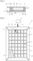
- FIG. 2 shows a cross-section through the energy storage device of FIG. 1 .
- FIG. 3 shows a top view of a charging arrangement.
- FIG. 4 shows a cross-sectional view of the charging arrangement according to FIG. 3 .
- FIG. 5 shows a second embodiment of a charging arrangement.
- FIG. 6 shows coupled housings on a ground surface which can be driven upon.
- FIG. 1 shows a schematic top view of an energy storage device 1 .
- the energy storage device 1 has a housing 2 , which is shown partially open at the top for improved illustration in FIG. 1 .
- a reinforcing structure 3 is provided within housing 2 , which in this case is cuboidal in shape and has a height of 10 cm, a width of 2.5 meters and a length of 5 meters, but may also have other dimensions, which structure 3 has steel support elements 4 which extend in a lattice-like manner horizontally, and where appropriate also vertically, and which support elements form segments or receptacles of equal size, in which—with the exception of one receptacle—battery modules 5 are inserted in a removable and thus replaceable manner, each of which comprises at least one battery cell, for example a pouch cell.
- a unit is inserted into a receptacle adjacent to a connection device 6 , which unit in this case implements a mains charging device 7 , components of a cooling device 8 and a control device 9 for controlling the operation of the energy storage device 1 , in particular the charging and discharging operation of the battery modules 5 , which are electrically coupled together for collectively charging an electric motor vehicle.
- the energy storage device 1 can be connected to a power grid 10 , for example a common domestic power grid, by means of the connection device 6 so that the battery modules 5 can be charged with power grid output from the power grid 10 and can also release energy back into this power grid 10 , so that the energy storage device 1 as a whole acts as a buffer storage (energy buffer).
- a motor vehicle charging device 11 for an electric motor vehicle can also be connected to the power grid 10 , so that the electric motor vehicle can thus be charged by means of electrical energy stored in the battery modules 5 .
- housing 2 is flat and without great vertical rise. On its upper side, shown in part, it has a top surface 12 on which a motor vehicle can drive, wherein the corresponding structural sturdiness is provided by the reinforcing structure 3 .
- Passenger vehicles (cars) were considered as the design standard for the reinforcing structure 3 in this case.
- the upper side of the housing 2 for example a cover plate in said location, which can also be understood as part of the reinforcement structure 3 , can have a structuring 13 .
- a friction-enhancing coating is also conceivable.
- ramps 15 are arranged on all sides of the housing 2 as drive-on aids 14 .
- the energy storage device 1 can thus be positioned on a ground surface which can be driven upon 16 , in particular a parking space for motor vehicles, for example in a garage, whereby the height of the ground surface which can be driven upon—which is prolonged by the top surface which can be driven upon 12 —is locally raised, but this does not result in any significant disadvantages, so that ultimately previously unused free space is used for the energy storage device 1 without leading to space problems, for example occupying storage spaces for bicycles and/or lawnmowers and/or making movement around a parked motor vehicle more difficult.
- FIG. 2 shows a partial cross-section of the energy storage device 1 of FIG. 1 .
- the support elements 4 acting as reinforcing struts are designed as square elements made of steel, which have an inner cavity 17 , which, in this case, is used to conduct a cooling line 18 for a cooling fluid of the cooling device 8 , electrical lines 19 and control signal lines 20 .
- FIG. 3 now shows a schematic top view of a charging arrangement 21 , in which, similar to FIG. 1 , the housing 2 is once again shown partially open at the top in order to be able to see the internal structure in more detail. Corresponding components are marked with the same reference numbers.
- the motor vehicle charging device 11 which is designed for inductive charging is now also integrated centrally in the housing 2 and can also be integrated with the mains charging device 7 as a complete charging device.
- the overall operation of the charging arrangement 21 continues to be controlled by means of the control device 9 .
- components of the cooling device 8 are moreover shown in a separate receptacle; however, the structural unit of FIG. 1 can also continue to be used.
- the motor vehicle charging device 11 has an induction coil 22 that can cooperate with a charging coil of an electric motor vehicle that is to be charged in order to charge a battery associated with an electric motor that is used as a drive motor of the electric motor vehicle.
- the motor vehicle charging device 11 in particular the induction coil 22 , is associated with a lifting device 23 by means of which, when the electric motor vehicle is correctly positioned on the top surface which can be driven upon 12 , the induction coil 22 aligned in a vertical direction with the charging coil of the electric motor vehicle can be lifted upwards to create a shorter distance between these two cooperating coils, which improves the efficiency of the charging operation.
- the latter may also have corresponding markings (not shown).
- a further special feature of the design of the charging arrangement 21 is that the motor vehicle charging device 11 can provide a higher motor vehicle charging capacity than the power output provided by the power grid 10 .
- the control device 9 is designed to provide the differential output between the power output of the power grid 10 and the vehicle charging capacity from the battery modules 5 .
- charging conditions in which the total motor vehicle charging capacity is drawn from the battery modules 5 are also possible, so that self-sufficient charging is made possible after the battery modules 5 have been charged, for example during the day using a photovoltaic device.
- the charging arrangement 21 may also be referred to as a “self-sufficient island” because of the self-sufficiency provided.
- FIG. 5 shows a second embodiment of a charging arrangement 21 ′, in which the motor vehicle charging device 11 is designed as a conductive system, which is to say it charges by means of a charging cable 26 , and is integrated with the mains charging device 7 to form a complete charging device 24 , which is furthermore controlled overall by the control device 9 .
- the charging cable 26 which can be pulled out of the housing 2 , is provided as the conductive charging connection 25 .
- FIG. 6 shows how an extension of the top surface which can be driven upon 12 by the addition of further housings 2 can take place, by means of a coupling arrangement 27 on the housings 2 .
- a coupling arrangement 27 on the housings 2 .
- three housings 2 are coupled to one another here using their respective coupling arrangement 27 , wherein the corresponding ramps 15 , which were likewise attached to profile sections of the coupling arrangement 27 , have been removed and profile sections of adjacent housings 2 now engage with one another in order to connect these housings to one another.
- Drive-on ramps 15 continue to be provided on the sides where no further housing 2 adjoins.
- connection devices 28 Electrical line connections and/or cooling line connections (cooling fluid connection) to the respective adjacent housing 2 can be established by means of connection devices 28 , so that it is possible, in particular, to operate the compound structure as one common, enlarged energy storage device 1 or charging arrangement 21 , 21 ′ by means of a common control device 9 and the total quantity of battery modules 5 .
- German patent application no. DE 10 2020 123475.9 filed Sep. 9, 2020, to which this application claims priority, is hereby incorporated herein by reference in its entirety.
Landscapes
- Engineering & Computer Science (AREA)
- Power Engineering (AREA)
- Transportation (AREA)
- Mechanical Engineering (AREA)
- Computer Networks & Wireless Communication (AREA)
- Electric Propulsion And Braking For Vehicles (AREA)
- Charge And Discharge Circuits For Batteries Or The Like (AREA)
Abstract
Description
Claims (17)
Applications Claiming Priority (2)
| Application Number | Priority Date | Filing Date | Title |
|---|---|---|---|
| DE102020123475.9A DE102020123475A1 (en) | 2020-09-09 | 2020-09-09 | Energy storage device for electrical energy, charging arrangement and method for installing an energy storage device or charging arrangement |
| DE102020123475.9 | 2020-09-09 |
Publications (2)
| Publication Number | Publication Date |
|---|---|
| US20220072970A1 US20220072970A1 (en) | 2022-03-10 |
| US12311791B2 true US12311791B2 (en) | 2025-05-27 |
Family
ID=80266566
Family Applications (1)
| Application Number | Title | Priority Date | Filing Date |
|---|---|---|---|
| US17/469,518 Active 2043-08-12 US12311791B2 (en) | 2020-09-09 | 2021-09-08 | Energy storage device for electric energy, charging arrangement and method for installing an energy storage device or charging arrangement |
Country Status (3)
| Country | Link |
|---|---|
| US (1) | US12311791B2 (en) |
| CN (1) | CN114228550A (en) |
| DE (1) | DE102020123475A1 (en) |
Families Citing this family (5)
| Publication number | Priority date | Publication date | Assignee | Title |
|---|---|---|---|---|
| DE102022105928A1 (en) | 2022-03-15 | 2023-09-21 | Audi Aktiengesellschaft | Energy storage arrangement and parking space for a motor vehicle |
| DE102022112277A1 (en) | 2022-05-17 | 2023-08-10 | Audi Aktiengesellschaft | Supply unit for wall mounting |
| KR102830184B1 (en) * | 2022-06-08 | 2025-07-03 | 박인석 | Apparatus and method for charging battery of electric vehicle |
| DE102022114733A1 (en) | 2022-06-10 | 2023-12-21 | Dr. Ing. H.C. F. Porsche Aktiengesellschaft | Floor charging device for electrically charging a traction battery |
| DE102022134174B4 (en) * | 2022-12-15 | 2024-06-27 | Schaeffler Technologies AG & Co. KG | Automated conductive charging system with cable contact via ground unit |
Citations (51)
| Publication number | Priority date | Publication date | Assignee | Title |
|---|---|---|---|---|
| US5612606A (en) * | 1994-09-15 | 1997-03-18 | David C. Guimarin | Battery exchange system for electric vehicles |
| US6307347B1 (en) * | 2000-08-02 | 2001-10-23 | Delphi Technologies, Inc. | Apparatus and method for recharging a vehicle |
| US6396239B1 (en) * | 2001-04-06 | 2002-05-28 | William M. Benn | Portable solar generator |
| US20030030411A1 (en) * | 2001-08-08 | 2003-02-13 | Hitachi, Ltd. | Vehicle operating system |
| US20070113921A1 (en) * | 2005-11-04 | 2007-05-24 | Capizzo Peter D | System for replenishing energy sources onboard different types of automotive vehicles |
| US20080067974A1 (en) * | 2006-09-18 | 2008-03-20 | Byd Company Limited | Electric Car Charging Systems |
| US20100109604A1 (en) | 2007-05-10 | 2010-05-06 | John Talbot Boys | Multi power sourced electric vehicle |
| US20110057512A1 (en) * | 2009-09-09 | 2011-03-10 | Sundial Power Pods, Llc | Mobile power system |
| US20120224326A1 (en) * | 2009-09-07 | 2012-09-06 | Markus Kohlberger | Modular battery structure |
| US20120235500A1 (en) * | 2008-09-27 | 2012-09-20 | Ganem Steven J | Wireless energy distribution system |
| US20120249065A1 (en) | 2011-04-01 | 2012-10-04 | Michael Bissonette | Multi-use energy management and conversion system including electric vehicle charging |
| US20120286730A1 (en) * | 2011-05-11 | 2012-11-15 | Richard William Bonny | Automatic Recharging Robot for Electric and Hybrid Vehicles |
| US20130017372A1 (en) * | 2011-01-18 | 2013-01-17 | Chris Mechling | Flexible mat with multiple foam layers |
| US8366371B2 (en) * | 2007-11-30 | 2013-02-05 | Sacket Material Handling Systems, Inc. | Industrial battery charging, storage and handling system |
| US20130169062A1 (en) * | 2011-05-27 | 2013-07-04 | Nissan Motor Co., Ltd. | Contactless electricity supply device |
| US20140021914A1 (en) * | 2012-07-19 | 2014-01-23 | Ford Global Technologies, Llc | Vehicle charging system |
| DE202013010416U1 (en) * | 2013-11-14 | 2014-02-11 | Hans-Joachim Lange | charging station |
| US8773079B2 (en) * | 2010-10-25 | 2014-07-08 | Muhammad Amzad Ali | Method of and plant for storage and retrieval of electrical energy |
| DE202014104247U1 (en) * | 2013-09-27 | 2014-09-18 | Edmond D. Krecké | Device for generating energy during the passage of motor vehicles |
| CN104505913A (en) | 2015-01-16 | 2015-04-08 | 蔡乌力吉 | Parking lot |
| US20150307068A1 (en) * | 2014-04-23 | 2015-10-29 | Tesla Motors, Inc. | Battery swapping system and techniques |
| US20160052407A1 (en) * | 2013-04-02 | 2016-02-25 | Pioneer Corporation | Contactless charging device and method for controlling power supply |
| CN105857108A (en) | 2016-05-23 | 2016-08-17 | 李洪伟 | Cloud graphene energy charging pile |
| US20170151881A1 (en) * | 2015-11-30 | 2017-06-01 | Hon Hai Precision Industry Co., Ltd. | Battery replacement system for electric vehicle and method of using the battery replacement system |
| US20170288465A1 (en) * | 2016-03-30 | 2017-10-05 | Tdk Corporation | Power feeding coil unit, wireless power feeding device and wireless power transmission device |
| US20170368949A1 (en) * | 2016-06-28 | 2017-12-28 | Ford Global Technologies, Llc | Fast charging battery system |
| DE102017103565A1 (en) * | 2017-02-22 | 2018-08-23 | Connaught Electronics Ltd. | BODY LOAD UNIT FOR CHARGING AN ELECTRICALLY DRIVEN VEHICLE |
| US20190039464A1 (en) * | 2017-08-01 | 2019-02-07 | Feaam Gmbh | Primary-side charging device, secondary-side charging device and method of charging a battery for a vehicle having an electric drive |
| DE102017119465A1 (en) | 2017-08-25 | 2019-02-28 | Dr. Ing. H.C. F. Porsche Aktiengesellschaft | Support device for receiving battery cells |
| US20190225098A1 (en) * | 2016-10-07 | 2019-07-25 | Bayerische Motoren Werke Aktiengesellschaft | Inductive Charging Unit for a Vehicle |
| DE102018204056A1 (en) * | 2018-03-16 | 2019-09-19 | Schäfer Elektronik Gmbh | Electric energy storage, stationary unit for such energy storage and energy storage module for the energy storage |
| CN110676906A (en) | 2019-10-17 | 2020-01-10 | 国网河北省电力有限公司电力科学研究院 | High-power charging pile test system based on energy storage battery and modular load integration |
| CN110733376A (en) | 2019-09-05 | 2020-01-31 | 夸蛾科技(上海)有限公司 | vehicle power battery autonomous loading and unloading system and unloading and charging method and loading method thereof to vehicle |
| US20200139835A1 (en) * | 2018-11-06 | 2020-05-07 | Jaro Fleet Technologies, Inc. | Charging System for Electric Vehicles |
| WO2020176860A1 (en) | 2019-02-28 | 2020-09-03 | Motion Fusion, Inc. | Autonomous wireless electric vehicle charging system |
| US20200406770A1 (en) * | 2019-06-28 | 2020-12-31 | Audi Ag | Charging plug for a charging station for transferring electric energy and a charging system therefor |
| US20210023955A1 (en) * | 2017-08-22 | 2021-01-28 | Zf Friedrichshafen Ag | Parking vehicle, method for parking an electric vehicle and for charging the battery of the electric vehicle, and parking space system |
| CN112428845A (en) * | 2019-08-21 | 2021-03-02 | 大众汽车股份公司 | Flexible power supply unit |
| US20210086631A1 (en) * | 2019-09-23 | 2021-03-25 | Abb Schweiz Ag | Vehicle charging connection using radio frequency communication |
| US20210162877A1 (en) * | 2018-06-12 | 2021-06-03 | Autostore Technology AS | Automated storage system with a container vehicle and a charging system |
| US20210188105A1 (en) * | 2019-12-18 | 2021-06-24 | Beam Global | Self-contained renewable inductive battery charger |
| US20210288512A1 (en) * | 2016-09-15 | 2021-09-16 | Nantenergy, Inc. | Hybrid battery system |
| US20220169135A1 (en) * | 2020-11-27 | 2022-06-02 | Free2Move Esolutions S.P.A. | Recharging system for electric vehicle batteries |
| US11485246B1 (en) * | 2021-04-05 | 2022-11-01 | Arnold Chase | Individualized vehicular charging mat |
| US20230052681A1 (en) * | 2020-04-27 | 2023-02-16 | Abb Schweiz Ag | Charger Plug Nozzle |
| US11597291B1 (en) * | 2019-10-17 | 2023-03-07 | Dell Products L.P. | Transferring power between a drone and a device during delivery |
| US20230089953A1 (en) * | 2020-03-05 | 2023-03-23 | Mahle International Gmbh | Stationary induction charging device for wireless energy transfer |
| US20230112408A1 (en) * | 2021-10-13 | 2023-04-13 | Kyndryl, Inc. | System to facilitate wireless charging of electronic device(s) |
| DE102022202925A1 (en) * | 2022-03-24 | 2023-09-28 | Mahle International Gmbh | Stationary induction charging device |
| US11780469B1 (en) * | 2020-04-24 | 2023-10-10 | Matthew MacGregor Roy | Unmanned autonomous recharging vehicle and system of recharging electric vehicle |
| US20240051420A1 (en) * | 2022-08-12 | 2024-02-15 | Audi Ag | Method for carrying out a charging process using an energy store of a motor vehicle and charging system |
Family Cites Families (9)
| Publication number | Priority date | Publication date | Assignee | Title |
|---|---|---|---|---|
| US8006793B2 (en) * | 2008-09-19 | 2011-08-30 | Better Place GmbH | Electric vehicle battery system |
| DE102014203859A1 (en) * | 2013-04-18 | 2014-10-23 | Robert Bosch Gmbh | A method for controlling the temperature of a traction battery disposed in a vehicle during a charging process at a charging station and charging station for carrying out such a method |
| CN204505913U (en) | 2015-03-20 | 2015-07-29 | 山东玉皇粮油食品有限公司 | A kind of oil press feed arrangement |
| US9969287B2 (en) * | 2015-07-07 | 2018-05-15 | Ford Global Technologies, Llc | Vehicle charging system |
| WO2017106104A1 (en) * | 2015-12-13 | 2017-06-22 | Tara Chand Singhal | Systems and methods for battery charge replenishment in an electric vehicle |
| DE102017110392A1 (en) * | 2017-01-07 | 2018-07-12 | Dieter Schumann | System for simultaneous storage and charging of multiple traction batteries for electric vehicles |
| DE102017117726A1 (en) * | 2017-08-04 | 2019-02-07 | enfas GmbH | Housing device for energy storage systems |
| DE102017009765A1 (en) * | 2017-10-18 | 2018-05-03 | Daimler Ag | Charging device for inductively charging an energy store of a motor vehicle |
| CN110001600B (en) * | 2018-12-07 | 2023-08-01 | 蔚来控股有限公司 | Quick battery replacement system and quick battery replacement method |
-
2020
- 2020-09-09 DE DE102020123475.9A patent/DE102020123475A1/en active Pending
-
2021
- 2021-09-07 CN CN202111041811.2A patent/CN114228550A/en active Pending
- 2021-09-08 US US17/469,518 patent/US12311791B2/en active Active
Patent Citations (95)
| Publication number | Priority date | Publication date | Assignee | Title |
|---|---|---|---|---|
| US5612606A (en) * | 1994-09-15 | 1997-03-18 | David C. Guimarin | Battery exchange system for electric vehicles |
| US6307347B1 (en) * | 2000-08-02 | 2001-10-23 | Delphi Technologies, Inc. | Apparatus and method for recharging a vehicle |
| US7492120B2 (en) * | 2001-04-06 | 2009-02-17 | Benn William M | Mobile solar generator |
| US6396239B1 (en) * | 2001-04-06 | 2002-05-28 | William M. Benn | Portable solar generator |
| US20020180404A1 (en) * | 2001-04-06 | 2002-12-05 | Benn William M. | Portable solar generator |
| US7898212B2 (en) * | 2001-04-06 | 2011-03-01 | Benn William M | Portable solar generator |
| US20100060229A1 (en) * | 2001-04-06 | 2010-03-11 | Benn William M | Portable solar generator |
| US20030030411A1 (en) * | 2001-08-08 | 2003-02-13 | Hitachi, Ltd. | Vehicle operating system |
| US6525510B1 (en) * | 2001-08-08 | 2003-02-25 | Hitachi, Ltd. | Vehicle operating system |
| US7602143B2 (en) * | 2005-11-04 | 2009-10-13 | Peter David Capizzo | System for replenishing energy sources onboard different types of automotive vehicles |
| US20090314382A1 (en) * | 2005-11-04 | 2009-12-24 | Peter David Capizzo | System for replenishing energy sources onboard different types of automatic vehicles |
| US20070113921A1 (en) * | 2005-11-04 | 2007-05-24 | Capizzo Peter D | System for replenishing energy sources onboard different types of automotive vehicles |
| US8164302B2 (en) * | 2005-11-04 | 2012-04-24 | Peter David Capizzo | System for replenishing energy sources onboard different types of automatic vehicles |
| US8461804B1 (en) * | 2005-11-04 | 2013-06-11 | Peter David Capizzo | System for replenishing energy sources onboard different types of automatic vehicles |
| US20080067974A1 (en) * | 2006-09-18 | 2008-03-20 | Byd Company Limited | Electric Car Charging Systems |
| US7768229B2 (en) * | 2006-09-18 | 2010-08-03 | Byd Company Limited | Electric car charging systems |
| US20100109604A1 (en) | 2007-05-10 | 2010-05-06 | John Talbot Boys | Multi power sourced electric vehicle |
| US8366371B2 (en) * | 2007-11-30 | 2013-02-05 | Sacket Material Handling Systems, Inc. | Industrial battery charging, storage and handling system |
| US20120235500A1 (en) * | 2008-09-27 | 2012-09-20 | Ganem Steven J | Wireless energy distribution system |
| US9065423B2 (en) * | 2008-09-27 | 2015-06-23 | Witricity Corporation | Wireless energy distribution system |
| US9112208B2 (en) * | 2009-09-07 | 2015-08-18 | MAHLE Behr GmbH & Co. KG | Modular battery structure |
| US20120224326A1 (en) * | 2009-09-07 | 2012-09-06 | Markus Kohlberger | Modular battery structure |
| US20110058664A1 (en) * | 2009-09-09 | 2011-03-10 | Sundial Power Pods, Llc | Mobile power system |
| US20120262849A1 (en) * | 2009-09-09 | 2012-10-18 | Sundial Power Pods, Llc | Mobile power system |
| US8254090B2 (en) * | 2009-09-09 | 2012-08-28 | Sundial Power Pods, Llc | Mobile power system |
| US8816528B2 (en) * | 2009-09-09 | 2014-08-26 | Sundial Power Pods, Llc | Mobile power system |
| US20110058312A1 (en) * | 2009-09-09 | 2011-03-10 | Sundial Power Pods, Llc | Mobile power system |
| US20110057512A1 (en) * | 2009-09-09 | 2011-03-10 | Sundial Power Pods, Llc | Mobile power system |
| US8599537B2 (en) * | 2009-09-09 | 2013-12-03 | Sundial Power Pods, Llc | Mobile power system |
| US20120218687A1 (en) * | 2009-09-09 | 2012-08-30 | Sundial Power Pods, Llc | Mobile power system |
| US8879242B2 (en) * | 2009-09-09 | 2014-11-04 | Sundial Power Pods, Llc | Mobile power system |
| US8797719B2 (en) * | 2009-09-09 | 2014-08-05 | Sundial Power Pods, Llc | Mobile power system |
| US8773079B2 (en) * | 2010-10-25 | 2014-07-08 | Muhammad Amzad Ali | Method of and plant for storage and retrieval of electrical energy |
| US20130017372A1 (en) * | 2011-01-18 | 2013-01-17 | Chris Mechling | Flexible mat with multiple foam layers |
| US20120249065A1 (en) | 2011-04-01 | 2012-10-04 | Michael Bissonette | Multi-use energy management and conversion system including electric vehicle charging |
| US20120286730A1 (en) * | 2011-05-11 | 2012-11-15 | Richard William Bonny | Automatic Recharging Robot for Electric and Hybrid Vehicles |
| US20130169062A1 (en) * | 2011-05-27 | 2013-07-04 | Nissan Motor Co., Ltd. | Contactless electricity supply device |
| US9553636B2 (en) * | 2011-05-27 | 2017-01-24 | Nissan Motor Co., Ltd. | Contactless electricity supply device with foreign object detector |
| US20140021914A1 (en) * | 2012-07-19 | 2014-01-23 | Ford Global Technologies, Llc | Vehicle charging system |
| US9467002B2 (en) * | 2012-07-19 | 2016-10-11 | Ford Global Technologies, Llc | Vehicle charging system |
| US9738167B2 (en) * | 2013-04-02 | 2017-08-22 | Pioneer Corporation | Contactless charging device and method for controlling power supply |
| US20160052407A1 (en) * | 2013-04-02 | 2016-02-25 | Pioneer Corporation | Contactless charging device and method for controlling power supply |
| DE202014104247U1 (en) * | 2013-09-27 | 2014-09-18 | Edmond D. Krecké | Device for generating energy during the passage of motor vehicles |
| DE202013010416U1 (en) * | 2013-11-14 | 2014-02-11 | Hans-Joachim Lange | charging station |
| US9688252B2 (en) * | 2014-04-23 | 2017-06-27 | Tesla, Inc. | Battery swapping system and techniques |
| US10300801B2 (en) * | 2014-04-23 | 2019-05-28 | Tesla, Inc. | Battery swapping system and techniques |
| US20150307068A1 (en) * | 2014-04-23 | 2015-10-29 | Tesla Motors, Inc. | Battery swapping system and techniques |
| US20170259675A1 (en) * | 2014-04-23 | 2017-09-14 | Tesla, Inc. | Battery swapping system and techniques |
| CN104505913A (en) | 2015-01-16 | 2015-04-08 | 蔡乌力吉 | Parking lot |
| US20170151881A1 (en) * | 2015-11-30 | 2017-06-01 | Hon Hai Precision Industry Co., Ltd. | Battery replacement system for electric vehicle and method of using the battery replacement system |
| US20170288465A1 (en) * | 2016-03-30 | 2017-10-05 | Tdk Corporation | Power feeding coil unit, wireless power feeding device and wireless power transmission device |
| DE102017106782A1 (en) | 2016-03-30 | 2017-10-05 | Tdk Corporation | Power supply coil unit, wireless power supply device, and wireless power transmission device |
| US10404102B2 (en) * | 2016-03-30 | 2019-09-03 | Tdk Corporation | Power feeding coil unit, wireless power feeding device and wireless power transmission device |
| CN105857108A (en) | 2016-05-23 | 2016-08-17 | 李洪伟 | Cloud graphene energy charging pile |
| US20170368949A1 (en) * | 2016-06-28 | 2017-12-28 | Ford Global Technologies, Llc | Fast charging battery system |
| US10589633B2 (en) * | 2016-06-28 | 2020-03-17 | Ford Global Technologies, Llc | Fast charging battery system |
| US20240097481A1 (en) * | 2016-09-15 | 2024-03-21 | Form Energy, Inc. | Hybrid battery system |
| US11670954B2 (en) * | 2016-09-15 | 2023-06-06 | Form Energy, Inc. | Hybrid battery system |
| US20210288512A1 (en) * | 2016-09-15 | 2021-09-16 | Nantenergy, Inc. | Hybrid battery system |
| US20190225098A1 (en) * | 2016-10-07 | 2019-07-25 | Bayerische Motoren Werke Aktiengesellschaft | Inductive Charging Unit for a Vehicle |
| US11667205B2 (en) * | 2016-10-07 | 2023-06-06 | Bayerische Motoren Werke Aktiengesellschaft | Inductive charging unit for a vehicle |
| DE102017103565A1 (en) * | 2017-02-22 | 2018-08-23 | Connaught Electronics Ltd. | BODY LOAD UNIT FOR CHARGING AN ELECTRICALLY DRIVEN VEHICLE |
| US20190039464A1 (en) * | 2017-08-01 | 2019-02-07 | Feaam Gmbh | Primary-side charging device, secondary-side charging device and method of charging a battery for a vehicle having an electric drive |
| DE102017117418A1 (en) | 2017-08-01 | 2019-02-07 | Feaam Gmbh | Primary-side charging device, secondary-side charging device and method for charging a battery for a vehicle with an electric drive |
| US20210023955A1 (en) * | 2017-08-22 | 2021-01-28 | Zf Friedrichshafen Ag | Parking vehicle, method for parking an electric vehicle and for charging the battery of the electric vehicle, and parking space system |
| DE102017119465A1 (en) | 2017-08-25 | 2019-02-28 | Dr. Ing. H.C. F. Porsche Aktiengesellschaft | Support device for receiving battery cells |
| DE102018204056A1 (en) * | 2018-03-16 | 2019-09-19 | Schäfer Elektronik Gmbh | Electric energy storage, stationary unit for such energy storage and energy storage module for the energy storage |
| US20210162877A1 (en) * | 2018-06-12 | 2021-06-03 | Autostore Technology AS | Automated storage system with a container vehicle and a charging system |
| US11993163B2 (en) * | 2018-06-12 | 2024-05-28 | Autostore Technology AS | Automated storage system with a container vehicle and a charging system |
| US20230339346A1 (en) * | 2018-11-06 | 2023-10-26 | Jaro Fleet Technologies, Inc. | Charging System for Electric Vehicles |
| US11718194B2 (en) * | 2018-11-06 | 2023-08-08 | Jaro Fleet Technologies, Inc. | Charging system for electric vehicles |
| US20200139835A1 (en) * | 2018-11-06 | 2020-05-07 | Jaro Fleet Technologies, Inc. | Charging System for Electric Vehicles |
| WO2020176860A1 (en) | 2019-02-28 | 2020-09-03 | Motion Fusion, Inc. | Autonomous wireless electric vehicle charging system |
| US20220134893A1 (en) * | 2019-02-28 | 2022-05-05 | Motion Fusion Inc. | Autonomous wireless electric vehicle charging system |
| US11584246B2 (en) * | 2019-06-28 | 2023-02-21 | Audi Ag | Charging plug for a charging station for transferring electric energy and a charging system therefor |
| US20200406770A1 (en) * | 2019-06-28 | 2020-12-31 | Audi Ag | Charging plug for a charging station for transferring electric energy and a charging system therefor |
| CN112428845A (en) * | 2019-08-21 | 2021-03-02 | 大众汽车股份公司 | Flexible power supply unit |
| CN110733376A (en) | 2019-09-05 | 2020-01-31 | 夸蛾科技(上海)有限公司 | vehicle power battery autonomous loading and unloading system and unloading and charging method and loading method thereof to vehicle |
| US20210086631A1 (en) * | 2019-09-23 | 2021-03-25 | Abb Schweiz Ag | Vehicle charging connection using radio frequency communication |
| US11312253B2 (en) * | 2019-09-23 | 2022-04-26 | Abb Schweiz Ag | Vehicle charging connection using radio frequency communication |
| US11597291B1 (en) * | 2019-10-17 | 2023-03-07 | Dell Products L.P. | Transferring power between a drone and a device during delivery |
| CN110676906A (en) | 2019-10-17 | 2020-01-10 | 国网河北省电力有限公司电力科学研究院 | High-power charging pile test system based on energy storage battery and modular load integration |
| US20210188105A1 (en) * | 2019-12-18 | 2021-06-24 | Beam Global | Self-contained renewable inductive battery charger |
| US11912144B2 (en) * | 2019-12-18 | 2024-02-27 | Beam Global | Self-contained renewable inductive battery charger |
| US20230089953A1 (en) * | 2020-03-05 | 2023-03-23 | Mahle International Gmbh | Stationary induction charging device for wireless energy transfer |
| US11820245B2 (en) * | 2020-03-05 | 2023-11-21 | Mahle International Gmbh | Stationary induction charging device for wireless energy transfer |
| US11780469B1 (en) * | 2020-04-24 | 2023-10-10 | Matthew MacGregor Roy | Unmanned autonomous recharging vehicle and system of recharging electric vehicle |
| US20230415784A1 (en) * | 2020-04-24 | 2023-12-28 | Matthew MacGregor Roy | Unmanned autonomous recharging vehicle and system of recharging electric vehicle |
| US20230052681A1 (en) * | 2020-04-27 | 2023-02-16 | Abb Schweiz Ag | Charger Plug Nozzle |
| US20220169135A1 (en) * | 2020-11-27 | 2022-06-02 | Free2Move Esolutions S.P.A. | Recharging system for electric vehicle batteries |
| US11485246B1 (en) * | 2021-04-05 | 2022-11-01 | Arnold Chase | Individualized vehicular charging mat |
| US20230112408A1 (en) * | 2021-10-13 | 2023-04-13 | Kyndryl, Inc. | System to facilitate wireless charging of electronic device(s) |
| US12155233B2 (en) * | 2021-10-13 | 2024-11-26 | Kyndryl, Inc. | System for wirelessly charging an electronic device |
| DE102022202925A1 (en) * | 2022-03-24 | 2023-09-28 | Mahle International Gmbh | Stationary induction charging device |
| US20240051420A1 (en) * | 2022-08-12 | 2024-02-15 | Audi Ag | Method for carrying out a charging process using an energy store of a motor vehicle and charging system |
Non-Patent Citations (4)
| Title |
|---|
| DE102017103565_Description_Machine_Translation.pdf (Year: 2018). * |
| DE102018204056A1_Description_Translation (Year: 2018). * |
| https://www.ncdot.gov/initiatives-policies/Transportation/bridges/historic-bridges/bridge-types/Pages/truss.aspx (Year: 2020). * |
| Merton Council "Appendix C1 Vehicle Length Data Summary" (Year: 2018). * |
Also Published As
| Publication number | Publication date |
|---|---|
| DE102020123475A1 (en) | 2022-03-10 |
| US20220072970A1 (en) | 2022-03-10 |
| CN114228550A (en) | 2022-03-25 |
Similar Documents
| Publication | Publication Date | Title |
|---|---|---|
| US12311791B2 (en) | Energy storage device for electric energy, charging arrangement and method for installing an energy storage device or charging arrangement | |
| US8829851B2 (en) | Single electric vehicle charger for electrically connecting to multiple electric vehicles simultaneously while automatically charging the multiple electric vehicles sequentially | |
| US9446676B2 (en) | Charging station for wired charging of electric vehicle | |
| CN102906959B (en) | Charging systems for electric vehicles | |
| US20120091955A1 (en) | Electric Vehicle Battery Recharge-Replacement System | |
| WO2019185589A1 (en) | Charging robot and method for operating same | |
| US20180345809A1 (en) | Recharging station for electric public transport vehicle, and facility comprising such a station | |
| US20130042542A1 (en) | Carport for a Motor Vehicle | |
| CN107735277A (en) | The method and system changed for power supply | |
| US20190217737A1 (en) | Autonomous robotic chargers and electric vehicle charging system | |
| CN104377763A (en) | Mobile electric vehicle charging system | |
| CN116080450A (en) | Motorized vehicle trailer charges at a single vehicle charging dock | |
| CN113954668A (en) | Charging pile robot and working method thereof | |
| CN112895958A (en) | Charging infrastructure for charging a motor vehicle | |
| CN111452651A (en) | Intelligent mobile charging system and method for electric automobile | |
| CN204156575U (en) | Removable charging system for electric automobile | |
| CN210283951U (en) | Mobile charging device | |
| US20240140230A1 (en) | Electric vehicle charging system with charging bus charging robot | |
| CN113665462A (en) | Multifunctional mobile rescue charging vehicle | |
| CN216101632U (en) | Charging pile robot | |
| JP7563352B2 (en) | Power Supply Equipment | |
| CN106836894A (en) | A kind of multi-storied garage automatic charging intelligence vehicle bearing pallet system | |
| CN106100052A (en) | A kind of removable multinomial charging pile | |
| US20240253496A1 (en) | Configurable electric vehicle charging system having centrally located power modules | |
| CN106994909A (en) | The automatic butt charging system and charging method of a kind of multi-storied garage |
Legal Events
| Date | Code | Title | Description |
|---|---|---|---|
| FEPP | Fee payment procedure |
Free format text: ENTITY STATUS SET TO UNDISCOUNTED (ORIGINAL EVENT CODE: BIG.); ENTITY STATUS OF PATENT OWNER: LARGE ENTITY |
|
| STPP | Information on status: patent application and granting procedure in general |
Free format text: DOCKETED NEW CASE - READY FOR EXAMINATION |
|
| AS | Assignment |
Owner name: AUDI AG, GERMANY Free format text: ASSIGNMENT OF ASSIGNORS INTEREST;ASSIGNOR:NEUDECKER, ANSGAR;REEL/FRAME:061545/0298 Effective date: 20221025 |
|
| STPP | Information on status: patent application and granting procedure in general |
Free format text: NON FINAL ACTION MAILED |
|
| STPP | Information on status: patent application and granting procedure in general |
Free format text: RESPONSE TO NON-FINAL OFFICE ACTION ENTERED AND FORWARDED TO EXAMINER |
|
| STPP | Information on status: patent application and granting procedure in general |
Free format text: FINAL REJECTION MAILED |
|
| STPP | Information on status: patent application and granting procedure in general |
Free format text: FINAL REJECTION MAILED |
|
| STCF | Information on status: patent grant |
Free format text: PATENTED CASE |