US12285351B2 - Ostomy appliance having conductive ink circuit for leakage detection - Google Patents
Ostomy appliance having conductive ink circuit for leakage detection Download PDFInfo
- Publication number
- US12285351B2 US12285351B2 US17/281,142 US201917281142A US12285351B2 US 12285351 B2 US12285351 B2 US 12285351B2 US 201917281142 A US201917281142 A US 201917281142A US 12285351 B2 US12285351 B2 US 12285351B2
- Authority
- US
- United States
- Prior art keywords
- rfid
- ostomy appliance
- ostomy
- conductive ink
- appliance
- Prior art date
- Legal status (The legal status is an assumption and is not a legal conclusion. Google has not performed a legal analysis and makes no representation as to the accuracy of the status listed.)
- Active, expires
Links
Images


Classifications
-
- A—HUMAN NECESSITIES
- A61—MEDICAL OR VETERINARY SCIENCE; HYGIENE
- A61F—FILTERS IMPLANTABLE INTO BLOOD VESSELS; PROSTHESES; DEVICES PROVIDING PATENCY TO, OR PREVENTING COLLAPSING OF, TUBULAR STRUCTURES OF THE BODY, e.g. STENTS; ORTHOPAEDIC, NURSING OR CONTRACEPTIVE DEVICES; FOMENTATION; TREATMENT OR PROTECTION OF EYES OR EARS; BANDAGES, DRESSINGS OR ABSORBENT PADS; FIRST-AID KITS
- A61F5/00—Orthopaedic methods or devices for non-surgical treatment of bones or joints; Nursing devices ; Anti-rape devices
- A61F5/44—Devices worn by the patient for reception of urine, faeces, catamenial or other discharge; Colostomy devices
- A61F5/445—Colostomy, ileostomy or urethrostomy devices
-
- A—HUMAN NECESSITIES
- A61—MEDICAL OR VETERINARY SCIENCE; HYGIENE
- A61F—FILTERS IMPLANTABLE INTO BLOOD VESSELS; PROSTHESES; DEVICES PROVIDING PATENCY TO, OR PREVENTING COLLAPSING OF, TUBULAR STRUCTURES OF THE BODY, e.g. STENTS; ORTHOPAEDIC, NURSING OR CONTRACEPTIVE DEVICES; FOMENTATION; TREATMENT OR PROTECTION OF EYES OR EARS; BANDAGES, DRESSINGS OR ABSORBENT PADS; FIRST-AID KITS
- A61F5/00—Orthopaedic methods or devices for non-surgical treatment of bones or joints; Nursing devices ; Anti-rape devices
- A61F5/44—Devices worn by the patient for reception of urine, faeces, catamenial or other discharge; Colostomy devices
- A61F5/4404—Details or parts
-
- A—HUMAN NECESSITIES
- A61—MEDICAL OR VETERINARY SCIENCE; HYGIENE
- A61F—FILTERS IMPLANTABLE INTO BLOOD VESSELS; PROSTHESES; DEVICES PROVIDING PATENCY TO, OR PREVENTING COLLAPSING OF, TUBULAR STRUCTURES OF THE BODY, e.g. STENTS; ORTHOPAEDIC, NURSING OR CONTRACEPTIVE DEVICES; FOMENTATION; TREATMENT OR PROTECTION OF EYES OR EARS; BANDAGES, DRESSINGS OR ABSORBENT PADS; FIRST-AID KITS
- A61F5/00—Orthopaedic methods or devices for non-surgical treatment of bones or joints; Nursing devices ; Anti-rape devices
- A61F5/44—Devices worn by the patient for reception of urine, faeces, catamenial or other discharge; Colostomy devices
- A61F5/443—Devices worn by the patient for reception of urine, faeces, catamenial or other discharge; Colostomy devices having adhesive seals for securing to the body, e.g. of hydrocolloid type seals, e.g. gels, starches, karaya gums
-
- A—HUMAN NECESSITIES
- A61—MEDICAL OR VETERINARY SCIENCE; HYGIENE
- A61F—FILTERS IMPLANTABLE INTO BLOOD VESSELS; PROSTHESES; DEVICES PROVIDING PATENCY TO, OR PREVENTING COLLAPSING OF, TUBULAR STRUCTURES OF THE BODY, e.g. STENTS; ORTHOPAEDIC, NURSING OR CONTRACEPTIVE DEVICES; FOMENTATION; TREATMENT OR PROTECTION OF EYES OR EARS; BANDAGES, DRESSINGS OR ABSORBENT PADS; FIRST-AID KITS
- A61F5/00—Orthopaedic methods or devices for non-surgical treatment of bones or joints; Nursing devices ; Anti-rape devices
- A61F5/44—Devices worn by the patient for reception of urine, faeces, catamenial or other discharge; Colostomy devices
- A61F5/445—Colostomy, ileostomy or urethrostomy devices
- A61F5/448—Means for attaching bag to seal ring
-
- G—PHYSICS
- G01—MEASURING; TESTING
- G01M—TESTING STATIC OR DYNAMIC BALANCE OF MACHINES OR STRUCTURES; TESTING OF STRUCTURES OR APPARATUS, NOT OTHERWISE PROVIDED FOR
- G01M3/00—Investigating fluid-tightness of structures
- G01M3/02—Investigating fluid-tightness of structures by using fluid or vacuum
- G01M3/04—Investigating fluid-tightness of structures by using fluid or vacuum by detecting the presence of fluid at the leakage point
- G01M3/16—Investigating fluid-tightness of structures by using fluid or vacuum by detecting the presence of fluid at the leakage point using electric detection means
Definitions
- the following description relates generally to an ostomy appliance having a conductive ink circuit for detecting leakage.
- An ostomy pouch includes opposing sidewalls defining an internal collection area.
- One of the sidewalls is provided with an inlet opening to receive a stoma, and means to secure the pouch to the user.
- Such means include, for example, an ostomy barrier, faceplate or skin barrier ring which may be connected to or formed integrally with the sidewall having the inlet opening.
- the ostomy barrier (or faceplate or barrier ring) may include adhesive on a skin-facing side to seal against the user's skin in an area surrounding the stoma.
- Such a system is intended to prevent or limit leakage of bodily fluid discharged from the stoma through the stoma/barrier/pouch environment.
- the seal formed between the ostomy barrier and the user may weaken, for example, with time, movement, improper installation and/or application of an external force, and thus, become susceptible to leaking.
- the user is unaware of or cannot easily assess an extent of weakening in the seal.
- a user is typically not aware of a weakened seal, and consequently, the risk of leakage, until a fluid discharged from the stoma leaks through to an exterior of the seal (i.e., the barrier) and becomes undesirably exposed to an external environment outside of the stoma/barrier/pouch environment.
- WO 2018/028756 (“WO '756”) discloses an ostomy appliance having a signal generator adapted to give a user or a health care professional a warning in time to change the appliance before leakage occurs by predetermining leakage or potential leakage of stomal fluids.
- a second material may be configured to dissipate in response to being exposed to stomal fluids and a signal generator, generally disposed under or within the second material, may set off an indicator signal when dissipation of the second material reaches a pre-defined threshold value.
- US Pat. Appl. Pub. No. 2017/0140103 (“US '103”), a parameter sensor that uses ink jet electrodes printed on paper can be used to measure leakage.
- the sensor paper is placed at a site of ostomy bag attachment to the stoma with the sensor paper surrounding the stoma. As the paper gets wet, from leakage, the electrodes change resistance and report this to a communicator.
- US '104 Another system for detecting leakage is described in U.S. Pat. No. 9,216,104 (“US '104”).
- a dressing is provided for application to an object that is, at least partly, electrically conductive.
- the dressing includes at least two electrodes adapted to be arranged at a distance from the partly electrically conductive object so that a first capacitor is formed between the first electrode and the partly electrically conductive object, and a second capacitor is formed between a second electrode and the partly electrically conductive object.
- a wetness sensor includes a substrate that carries a tuned RF circuit.
- the circuit includes a conductive pattern applied to the substrate, a capacitor, and a jumper disposed on a same side of the substrate.
- the conductive pattern includes an inductive coil and an inner and outer terminus.
- the jumper electrically couples the inner terminus to the outer terminus and also includes a frangible link which, when contacted by a target fluid, produces a drastic change in the operation of the RF circuit. The drastic change can be interpreted by a remote reader as a “wet” condition.
- Contact of the frangible link by the target fluid may change the impedance or resistance of the RF circuit by at least a factor of 5, 10, 100, or more, and/or may cause the frangible link to disintegrate to produce an open circuit, and/or may substantially render the RF circuit inoperative.
- the system of US '302 is part of an absorbent article or garment, such as a diaper, and is not configured for an ostomy environment.
- an ostomy appliance such as an ostomy hydrocolloid or ostomy pouch having such an ostomy hydrocolloid, in which leakage may be detected using a conductive ink circuit. It is also desirable to provide an ostomy appliance in which a notification may be provided to the user based on the leakage detection, before the leakage reaches the exterior environment. It is also desirable to provide an ostomy appliance in which an extent of leakage may be detected.
- an ostomy appliance includes a substrate and at least one Radio Frequency Identification (RFID) circuit disposed on the substrate.
- the at least one RFID circuit includes a RFID transponder having an antenna and a conductive ink connected in series with the antenna and the RFID transponder.
- the conductive ink is a dissolvable ink configured to dissolve in response to exposure to moisture.
- the RFID circuit is in a closed condition when the conductive ink extends continuously between the RFID transponder and the antenna.
- the RFID circuit is in an open condition when at least a portion of the conductive ink is dissolved.
- the at least one RFID circuit may include a plurality of the RFID circuits. Each RFID circuit of the plurality RFID circuits may have a different transverse dimension than each of the other RFID circuits of the plurality of RFID circuits.
- the RFID circuits may be concentrically positioned relative to one another.
- the RFID circuits of the plurality of RFID circuits may extend along respective, substantially circular paths.
- the ostomy appliance may further include an ostomy hydrocolloid having a skin barrier, a backing layer and a stoma opening.
- the at least one RFID circuit may be disposed on the skin barrier.
- the ostomy appliance may further include an ostomy pouch coupled to the ostomy hydrocolloid.
- the ostomy appliance may further include a wearable device communicatively connected to the at least one RFID circuit.
- the wearable device may include a housing, a power supply, a controller operably connected to the power supply and an RFID transceiver operably connected to a transceiver antenna and the controller.
- the RFID transceiver may be configured to transmit a first signal
- the RFID transponder may be configured to transmit a second signal in response receiving the first signal with the RFID circuit in a closed condition.
- the RFID may not be configured to transmit the second signal with the RFID circuit in the open condition.
- the controller may be configured to determine a leakage condition of the ostomy appliance based on the second signal.
- the wearable device may also include an output device configured to output a notification based on the determined leakage condition of the ostomy appliance.
- the wearable device may also include a wireless transceiver.
- the ostomy appliance may further include a personal notification device communicatively connected to the wearable device via a wireless transceiver.
- the personal notification device may be configured to output a notification based on the determined leakage condition.
- the personal notification device may be a smartphone.
- an ostomy appliance may comprise a hydrocolloid and a leak detection system.
- the leakage detections system may comprise at least one ink jet electrode arranged on the hydrocolloid.
- the at least one ink jet electrode may be configured to reduce a conductivity when exposed to ostomy leakage fluid.
- the leak detection system may be configured to measure electrical current flowing through the at least one ink jet electrode and detect a leakage by measuring a change in electrical current flowing through the at least one ink jet electrode.
- the leak detection system may further include at least one RFID circuit comprising a RFID transponder having an antenna, wherein the at least one ink jet electrode is connected in series with the antenna and the RFID transponder.
- the RFID circuit may be configured to form a closed circuit with the at least one ink jet electrode extending between the RFID transponder and the antenna.
- the at least one ink jet electrode may be formed from a conductive ink that dissolves when exposed to ostomy leakage fluid, wherein the RFID circuit becomes an open condition when at least a portion of the at least one ink jet electrode is dissolved.
- the at least one ink jet electrode may be configured to absorb ostomy leakage fluid and swell, wherein the conductivity is reduced when the at least one ink jet electrode absorbs the fluid and swells.
- FIG. 1 is a perspective view of an ostomy appliance, according to an embodiment
- FIG. 2 is another perspective view of the ostomy appliance of FIG. 1 ;
- FIG. 3 is a plan view showing a body-facing side of the ostomy appliance of FIG. 2 , according to an embodiment
- FIG. 4 is a perspective view of a wearable device, according to an embodiment
- FIG. 5 is an exploded view of the wearable device, according to an embodiment
- FIG. 6 shows an ostomy hydrocolloid and the wearable device of the ostomy appliance, according to an embodiment
- FIG. 7 shows the ostomy hydrocolloid and an ostomy pouch of the ostomy appliance, according to an embodiment
- FIG. 8 schematically shows a personal notification device communicatively connected to the ostomy appliance, according to an embodiment
- FIGS. 9 A- 9 B show the RFID circuit being applied to the ostomy hydrocolloid, according to an embodiment
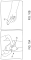
- FIGS. 10 A- 10 B show a user setting up the ostomy appliance for use, according to an embodiment
- FIGS. 11 A- 11 C show examples the ostomy appliance, in use, configured to detect stoma fluid leakage
- FIGS. 12 A- 12 C show examples of a user tending to the ostomy appliance in response to receiving a notification of stoma fluid leakage.
- FIG. 1 is a perspective view showing a pouch-facing side of an ostomy appliance 10 , according to an embodiment
- FIG. 2 is another perspective view of the ostomy appliance 10 of FIG. 1 , showing a body-facing side of the appliance 10
- the ostomy appliance 10 includes an ostomy hydrocolloid 11 configured to connect an ostomy pouch 210 ( FIG. 7 ) to a user.
- the ostomy hydrocolloid 11 may be, for example, any of an ostomy barrier, an ostomy faceplate or an ostomy skin barrier ring.
- the ostomy hydrocolloid 11 generally includes a backing layer 12 ( FIG. 1 ) and a skin barrier 14 ( FIG. 2 ).
- the backing layer 12 may be formed by a soft, flexible material that is generally soft and non-irritable to the user's skin, such as a nonwoven or foam material.
- an adhesive may be provided on the body-facing side 16 of the ostomy appliance 10 for adhering to the user's skin.
- the skin barrier 14 may include a known, medical grade adhesive suitable for adhering to the user's skin and sealing around a stoma.
- the ostomy appliance 10 may further include a coupling section 18 at the pouch-facing side 20 of the ostomy appliance 10 .
- the coupling section 18 may be a known ostomy appliance flange configured for coupling to an ostomy pouch in a two-piece pouch configuration.
- the coupling section 18 may be a known bag-barrier interface in a one-piece pouch configuration.
- the ostomy appliance 10 includes a stoma opening 22 extending through the backing layer 12 and the skin barrier 14 .
- the stoma opening 22 is configured to receive the stoma and allow for flow of stoma fluid into the ostomy pouch.
- FIG. 3 is a plan view of the body-facing side 16 of the ostomy appliance 10 , according to an embodiment.
- a Radio Frequency Identification (RFID) circuit 24 is provided at the skin barrier 14 .
- the RFID circuit 24 includes a RFID transponder 26 having an antenna 28 and an electrically conductive ink 30 connected in series with the antenna 28 and the RFID transponder 26 .
- the RFID circuit 24 may also include a suitable device (not shown) for detecting an electrical resistance, for example, by detecting a voltage drop across the circuit.
- the RFID circuit 24 includes a plurality of the RFID circuits 24 .
- the plurality of RFID circuits 24 may include, for example, at least two RFID circuits 24 , and up to ten RFID circuits 24 . Alternatively, a single RFID circuit 24 may be provided.
- the RFID transponder 26 is configured to operate in accordance with a local standard.
- the RFID transponder 26 may operate in accordance with Ultra-High Frequency, or UHF, RFID technology, which operates at frequency range from 902 MHz to 928 MHz.
- UHF Ultra-High Frequency
- the present disclosure is not limited to such a frequency range, however.
- the conductive ink 30 may be configured to degrade and/or change a property when exposed to moisture.
- the conductive ink 30 may be configured to absorb moisture and/or fluid and swell and become non-conductive.
- the conductive ink 30 may be dissolvable when exposed to moisture.
- the conductive ink 30 portions of the RFID circuit 24 may also be referred to as “ink jet electrodes” herein.
- the conductive ink 30 may be carbon-based, such as a carbon-based conductive ink sold by BARE CONDUCTIVE. However, other electrically conductive inks are envisioned for use in the RFID circuit 24 as well.
- the RFID circuit 24 is in a closed condition when the conductive ink 30 extends continuously between the RFID transponder 26 and the antenna 28 , such that an electrical current may flow through the circuit 24 .
- the RFID circuit 24 is in an open condition when at least a portion of the conductive ink 30 is dissolved, thereby preventing or limiting flow of an electrical current in the circuit.
- the RFID circuit 24 may be formed on a substrate 32 for example, by printing.
- the substrate 32 may be a release paper ( FIG. 3 ) configured to be applied over the body-facing side 16 of the ostomy appliance 10 to dispose the RFID circuit 24 on the skin barrier 14 .
- the RFID circuit 24 may be manufactured independently from the ostomy hydrocolloid 11 and provided separately as an accessory for use with the ostomy hydrocolloid 11 .
- the substrate 32 may be formed having the stoma opening 22 , a stoma opening starter hole, or be configured to have the stoma opening 22 formed therein in a post-manufacturing step, for example, by the user.
- the substrate 32 may be the skin barrier 14 of the ostomy hydrocolloid 11 ( FIG. 2 ) such that the RFID circuit 24 is disposed directly on the skin barrier 14 .
- each RFID circuit 24 of the plurality of RFID circuits 24 may be formed having a different transverse dimension.
- each RFID circuit 24 may have a radius different from the other RFID circuits 24 .
- the RFID circuits 24 may be arranged concentrically relative to one another. Further still, the RFID circuits 24 may be concentric with the stoma opening 22 of the ostomy appliance 10 .
- the RFID circuits 24 extend along respective substantially circular or curved paths. However, other suitably shaped paths are envisioned as well.
- the RFID circuits 24 extend 360 degrees, or substantially 360 degrees, about the stoma opening 22 .
- the RFID circuits 24 may extend along a path only partially about the stoma opening at a location where leakage is most likely to occur.
- FIG. 4 is a perspective view of a wearable device 110 according to an embodiment.
- the wearable device 110 includes a housing 112 .
- the housing 112 is preferably made from a relatively lightweight, durable material.
- the material of the housing 112 is preferably a skin-friendly material as well.
- the housing 112 may include a fastener 114 configured to secure the wearable device 110 to the user, for example, on an article of clothing or other accessory.
- Examples of the fastener 114 include, but are not limited to, a clip, a hook-and-loop fastener, a button, a snap, a pin, an adhesive, a strap or other flexible material, a buckle, and the like.
- FIG. 5 is an exploded view of the wearable device 110 according to an embodiment.
- the wearable device 110 includes, for example, a controller 116 , a power supply 118 , such as a battery, a RFID transceiver 120 (also referred to as a RFID reader), and a first charging interface 122 , such as pogo pins, for facilitating charging the power supply 118 .
- the wearable device 110 may also include a wireless transceiver 124 configured to facilitate wireless communications with a personal notification device 310 ( FIG. 8 ).
- the controller 116 , power supply 118 , RFID transceiver 120 and wireless transceiver 124 may be operably connected to one another.
- a printed circuit board (PCB) 126 may also be provided and connected to the various components described above.
- PCB printed circuit board
- the controller 116 may be a microcontroller and may include a processor, memory and communication module.
- the processor is configured to execute program instructions stored in the memory and the communication module is configured to send or receive signals to and from the processor to carry out operations based on the program instructions.
- the wireless transceiver 124 may be configured for wireless communications according to known wireless communication standards and protocols and may communicate over known communication networks, such as personal area networks, wireless local area networks, metropolitan area networks and wide area networks. Accordingly, the wireless transceiver 124 may be configured for various wireless communications including, but not limited to, Bluetooth, Bluetooth Low Energy, Near-Field Communication, WiFi, WiMax, cellular LTE or other cellular radio communications.
- the RFID transceiver 120 is operably connected to a transceiver antenna 128 , which may be formed as a coil, to facilitate RFID communications. Accordingly, the RFID transceiver 120 may be configured to transmit a first signal, such as an interrogation signal, and receive a second signal, such as a response signal as further described below.
- a first signal such as an interrogation signal
- a second signal such as a response signal as further described below.
- the wearable device 110 may further include one or more output devices 130 , 132 configured to output a notification.
- the one or more output devices 130 , 132 may include, for example, one or more of a visual indicator such as a light emitting device, an audio indicator such as a speaker, or a vibratory indicator such as a vibrating motor.
- the one or more output devices 130 , 132 include a light emitting diode (LED) 130 and a vibrating motor 132 .
- LED light emitting diode
- the wearable device 110 may further include an operating switch 134 , which may be formed as pushbutton, sliding switch, rocker switch, haptic switch or other similar, suitable switch or button.
- the switch 134 may be operably coupled to the power supply 118 and function as an ON/OFF switch for the wearable device 110 .
- the operating switch 134 may also function to sync or pair the wearable device 110 with the sensor 24 of the ostomy appliance 10 to facilitate communication between the one or more RFID circuits 24 and the wearable device 110 .
- a separate sync or pair switch may be provided for the syncing or pairing function.
- syncing or pairing may occur when the wearable device 110 is powered on and positioned within range of the RFID circuit 24 .
- the range may be up to about 1 meter.
- the first and second signals may be transmitted between the RFID transponder 26 and the RFID transceiver 120 within a range of up to about 1 meter.
- the RFID circuit 24 is configured to receive the first signal from the RFID transceiver 120 . With the RFID circuit 24 in the closed condition, the receipt of the first signal induces an electrical current through antenna 28 and conductive ink 30 to provide power to the RFID transponder 26 .
- the RFID transponder 26 may transmit the second signal to the RFID transceiver 120 .
- the second signal includes RFID information in the form of analog or digital data. RFID information may include, for example, identification information of the RFID transponder 26 or circuit 24 from which the second signal is transmitted.
- the conductive ink 30 may be configured to degrade and/or change a property when exposed to moisture.
- the conductive ink 30 is configured to dissolve in response to exposure to moisture. Accordingly, stoma fluid leakage from the stoma opening 22 may contact the conductive ink 30 causing the conductive ink 30 to dissolve. With at least a portion of the conductive ink 30 dissolved, the RFID circuit 24 becomes an open circuit. In the open circuit condition, electrical current may not be provided to the RFID transponder 26 , and thus, the second signal may not be transmitted.
- the ostomy appliance 10 may be configured to facilitate transport of stoma fluid leakage toward the conductive ink 30 for timely leak detection.
- the hydrocolloid 11 of the ostomy appliance 10 may be configured to guide and transport stoma fluid leakage toward the conductive ink 30 .
- the ostomy appliance 10 may include a wick arranged and configured to guide and transport ostomy fluid leakage toward the conductive ink 30 .
- the RFID transceiver 120 is configured to receive the second signal and the controller 116 is configured to process the second signal to determine a condition of the ostomy appliance 10 .
- the determined condition may indicate that stoma fluid leakage is not detected, that stoma fluid leakage is detected, and in one embodiment, an extent of the detected stoma fluid leakage.
- the extent of stoma fluid leakage may be either qualitative or quantitative, and may refer to a distance or location relative to a reference point on the ostomy hydrocolloid 11 where stoma fluid leakage has been detected.
- the reference point may be, for example the stoma opening 22 or an outer periphery of the ostomy hydrocolloid 11 .
- the controller 116 may determine that stoma fluid leakage is not detected if the second signal is received from the RFID circuit 24 , or each RFID circuit 24 of the plurality of RFID circuits 24 , in response to transmission of the first signal.
- the controller 116 may determine that stoma fluid leakage is detected if the second signal is not received from the RFID circuit 24 , or the second signal is received from less than all RFID circuits 24 of the plurality of RFID circuits 24 , in response to transmission of the first signal.
- the controller 116 may determine an extent of the detected stoma fluid leakage, for example, by determining which RFID circuits 24 of the plurality of RFID have, or have not, transmitted the second signal in response to transmission of the first signal. In one embodiment, a position of the RFID circuits 24 on the ostomy hydrocolloid 11 may be known, such that a quantitative indication of the extent of the stoma fluid leakage may be determined.
- an electrical resistance may be detected in the RFID circuit 24 .
- the detected electrical resistance may be included as resistance information in the RFID information.
- the controller 116 may then determine whether or not a stoma fluid leak is present at an RFID circuit 24 based on the resistance information received in the second signal. For example, the controller 116 may determine that a stoma fluid leak is present if the resistance information is transmitted with the second signal. Alternatively, the controller 116 may compare the received resistance information to stored, predetermined threshold resistance information.
- the wearable device 110 is configured to output a notification based on the determined condition of the ostomy appliance 10 .
- the controller 116 may be configured to output the notification by controlling one or more of the output devices 130 , 132 based on the determined condition.
- the controller 116 may control the LED 130 to emit light in one more colors depending on the determined condition.
- the LED 130 may emit a green light to indicate that no stoma fluid leakage is detected, a yellow light to indicate that a non-urgent stoma fluid leak is detected which does not require immediate attention, and a red light indicating that a stoma fluid leak is detected at an extent such that the ostomy appliance should be promptly tended to.
- the “non-urgent” condition of the stoma fluid leak may be determined based on the extent of stoma fluid leak.
- the controller 116 may determine a rate of change of a stoma fluid leak, for example, by monitoring which RFID circuits 24 transmit the second signal with respect to time.
- the determined condition may be based, at least in part, on the determined rate of change.
- the LED 130 could also be controlled, for example, to blink, blink at different frequencies, or emit light at varying intensities, or any combination thereof, based on the determined condition.
- the controller 116 may control the vibrating motor 132 , for example, to vibrate, not vibrate, vibrate intermittently, or at different intensities, or any combination thereof, based on the determined condition.
- an audible output device (not shown) may be controlled to emit, for example, a sound, at different time intervals, pitches, volumes, or any combination thereof, based on the determined condition. Notifications including combinations of the above may be output as well.
- FIG. 6 shows examples of the ostomy hydrocolloid 11 and the wearable device 110 of the ostomy appliance 10 , according to an embodiment.
- a charging device 136 may be provided having a second charging interface (not shown) configured for electrical connection to the first charging interface 122 of the wearable device 110 , to charge the power supply 118 .
- FIG. 7 shows the ostomy hydrocolloid 11 and an ostomy pouch 210 of the ostomy appliance 10 , according to an embodiment.
- the ostomy pouch 210 includes an inlet opening 212 configured to allow stoma fluid to be received in an internal collection area.
- the inlet opening 212 may be disposed in fluid communication with the stoma opening 22 .
- the pouch 210 may include a pouch coupling section 214 configured for coupling to the coupling section 18 of the ostomy hydrocolloid 11 .
- FIG. 8 schematically shows a personal notification device 310 communicatively connected to the ostomy appliance 10 , according to an embodiment.
- the personal notification device 310 may be included as a component of the ostomy appliance 10 .
- the personal notification device 310 may be communicatively connected to the wearable device 110 , for example, over a wireless communication interface by way of the wireless transceiver 124 .
- the personal notification device 310 may be a mobile communication device, such as a smart phone or other mobile phone.
- the personal notification device 310 may be another mobile communication device, a portable electronic device, or other electronic device configured for communication, directly or indirectly, with the wearable device 110 .
- Such devices may include, but are not limited to, tablets, laptop computers, desktop computers, smart speakers, connected wearable accessories such as fitness trackers, smart watches and the like, smart televisions, personal digital assistants and the like.
- the wearable device 110 may be paired, synced, or otherwise communicatively connected to the personal notification device 310 with a known pairing or syncing operation, which may be initiated, for example, by operation of the operating switch 134 .
- the personal notification device 310 may determine the condition of the ostomy appliance 10 and output a notification based on the determined condition, in a manner similar to that described above with respect to the controller 116 .
- the wearable device 110 may transmit the determined condition of the ostomy appliance 10 to the personal notification device 310 .
- the personal notification device 310 may include one or more output devices, such as those described above for example, for outputting a notification based on the determined condition. It is further envisioned that different, or additional, notifications based on the determined condition may be provided on a display screen 312 of the personal notification device 310 . For example, graphics, animations and the like may be provided as a notification on the display screen.
- the personal notification device 310 may receive the determined condition, or determine the condition, of the ostomy appliance 10 at predetermined time intervals. Alternatively, or in addition, a user may operate the personal notification device 310 to request the determined condition from the wearable device 110 or to determine the condition.
- the personal notification device 310 may perform functions according to a smartphone application directed to the ostomy appliance 10 .
- the smartphone application may include program instructions stored in a memory unit of the smartphone which are configured to be executed by a processor of the smartphone to control the smartphone to perform the functions.
- the smartphone may be controlled to generate and output the notification.
- the smartphone may also be controlled to store additional data and enable further communications.
- the smartphone may be configured to track leaks or degradation of the ostomy hydrocolloid 11 , behaviors and activities that could potentially affect wear time, including, but not limited to: pouch changes, diet, leakage occurrence, gas occurrence and physical activity.
- the smartphone may be configured to provide a platform to share practices and advice from other users and clinicians.
- the smartphone may be configured to allow for communication with other information sources, for example, to access video tutorials providing additional education and instruction on managing a stoma.
- the smartphone may be configured to allow for pictures to be taken and stored of the stoma and skin health.
- the smartphone may be configured to facilitate contact with a wound, ostomy and continence (WOC) nurse (also referred to as an enterostomal therapy (ET) nurse), for example, to troubleshoot or share stoma and skin health conditions.
- WOC wound, ostomy and continence
- ET enterostomal therapy
- the smartphone may be configured to allow for ordering or automatic re-ordering of an ostomy appliance 10 or related supplies when a determination is made that such supplies are running low.
- the smartphone may be configured to provide usage and patient data to, for example, the ostomy appliance manufacturer, such as marketing, research and product support teams.
- usage and data may be provided, for example, after a user opts-in, and the data may be provided securely, anonymously, and in accordance with local privacy laws and regulations, to support health economics.
- a smartphone application executed to control functions of a smartphone according to the examples above.
- a similar software application could be executed by a tablet or other portable device, a remote server configured to be accessed by the user through a known communications interface, or at a personal computing device, such as a laptop or desktop computer, or some combination of the above.
- FIGS. 9 A and 9 B show examples of the RFID circuit 24 being applied to the ostomy hydrocolloid 11 .
- the RFID circuit 24 may be disposed on the substrate 32 ( FIG. 9 A ).
- the RFID circuit 24 may be applied to the body-facing side 16 of the ostomy hydrocolloid 11 , and a release layer 34 may be removed ( FIG. 9 B ) to expose an adhesive on the RFID circuit 24 for adhering to a user's skin.
- FIGS. 10 A and 10 B show a user setting up the ostomy appliance 10 for use, according to an embodiment.
- the ostomy appliance 10 including the ostomy pouch 210
- the wearable device 110 is powered on and communicatively coupled to the ostomy appliance 10 , for example, to the one or more RFID circuit 24 .
- FIGS. 11 A- 11 C show examples the ostomy appliance 10 , in use, configured to detect stoma fluid leakage.
- FIG. 11 A shows the ostomy appliance 10 , including the ostomy pouch 210 and the wearable device 110 connected to the user.
- FIG. 11 B shows the user in a social setting and
- FIG. 11 C shows ostomy appliance 10 with a stoma fluid leakage ‘L’ forming along the ostomy hydrocolloid 11 .
- FIGS. 12 A- 12 C show examples of a user tending to the ostomy appliance 10 in response to receiving a notification of stoma fluid leak ‘L’.
- a stoma fluid leak ‘L’ is detected by a plurality of the RFID circuits 24 and a notification is provided by the wearable device 110 .
- the user discreetly senses the notification.
- the user tends to the ostomy appliance 10 .
Landscapes
- Health & Medical Sciences (AREA)
- Heart & Thoracic Surgery (AREA)
- Animal Behavior & Ethology (AREA)
- Epidemiology (AREA)
- Nursing (AREA)
- Orthopedic Medicine & Surgery (AREA)
- Engineering & Computer Science (AREA)
- Biomedical Technology (AREA)
- Veterinary Medicine (AREA)
- Public Health (AREA)
- Vascular Medicine (AREA)
- Life Sciences & Earth Sciences (AREA)
- General Health & Medical Sciences (AREA)
- General Physics & Mathematics (AREA)
- Physics & Mathematics (AREA)
- Chemical & Material Sciences (AREA)
- Dispersion Chemistry (AREA)
- Orthopedics, Nursing, And Contraception (AREA)
- Absorbent Articles And Supports Therefor (AREA)
Abstract
Description
Claims (11)
Priority Applications (1)
| Application Number | Priority Date | Filing Date | Title |
|---|---|---|---|
| US17/281,142 US12285351B2 (en) | 2018-10-09 | 2019-10-03 | Ostomy appliance having conductive ink circuit for leakage detection |
Applications Claiming Priority (3)
| Application Number | Priority Date | Filing Date | Title |
|---|---|---|---|
| US201862743233P | 2018-10-09 | 2018-10-09 | |
| US17/281,142 US12285351B2 (en) | 2018-10-09 | 2019-10-03 | Ostomy appliance having conductive ink circuit for leakage detection |
| PCT/US2019/054484 WO2020076607A1 (en) | 2018-10-09 | 2019-10-03 | Ostomy appliance having conductive ink circuit for leakage detection |
Related Parent Applications (1)
| Application Number | Title | Priority Date | Filing Date |
|---|---|---|---|
| PCT/US2019/054484 A-371-Of-International WO2020076607A1 (en) | 2018-10-09 | 2019-10-03 | Ostomy appliance having conductive ink circuit for leakage detection |
Related Child Applications (1)
| Application Number | Title | Priority Date | Filing Date |
|---|---|---|---|
| US19/093,646 Division US20250221843A1 (en) | 2018-10-09 | 2025-03-28 | Ostomy appliance having conductive ink circuit for leakage detection |
Publications (2)
| Publication Number | Publication Date |
|---|---|
| US20210338471A1 US20210338471A1 (en) | 2021-11-04 |
| US12285351B2 true US12285351B2 (en) | 2025-04-29 |
Family
ID=68296817
Family Applications (2)
| Application Number | Title | Priority Date | Filing Date |
|---|---|---|---|
| US17/281,142 Active 2041-12-07 US12285351B2 (en) | 2018-10-09 | 2019-10-03 | Ostomy appliance having conductive ink circuit for leakage detection |
| US19/093,646 Pending US20250221843A1 (en) | 2018-10-09 | 2025-03-28 | Ostomy appliance having conductive ink circuit for leakage detection |
Family Applications After (1)
| Application Number | Title | Priority Date | Filing Date |
|---|---|---|---|
| US19/093,646 Pending US20250221843A1 (en) | 2018-10-09 | 2025-03-28 | Ostomy appliance having conductive ink circuit for leakage detection |
Country Status (9)
| Country | Link |
|---|---|
| US (2) | US12285351B2 (en) |
| EP (2) | EP3863575B1 (en) |
| CN (1) | CN112969434B (en) |
| AU (1) | AU2019359129B2 (en) |
| CA (1) | CA3115737A1 (en) |
| DK (1) | DK3863575T3 (en) |
| HU (1) | HUE067287T2 (en) |
| LT (1) | LT3863575T (en) |
| WO (1) | WO2020076607A1 (en) |
Cited By (2)
| Publication number | Priority date | Publication date | Assignee | Title |
|---|---|---|---|---|
| US20240009020A1 (en) * | 2017-12-22 | 2024-01-11 | Coloplast A/S | Ostomy appliance with leakage detection |
| US12521269B2 (en) | 2017-12-22 | 2026-01-13 | Coloplast A/S | Base plate and sensor assembly part of a medical system having a moisture sensor |
Families Citing this family (69)
| Publication number | Priority date | Publication date | Assignee | Title |
|---|---|---|---|---|
| AU2008245845A1 (en) | 2007-04-24 | 2008-11-06 | Convatec Technologies Inc. | Closure system for a drainable pouch |
| JP5474779B2 (en) | 2007-06-12 | 2014-04-16 | コンバテック・テクノロジーズ・インコーポレイテッド | Ostomy device |
| US10285847B2 (en) | 2011-09-29 | 2019-05-14 | Convatec Technologies Inc. | Ostomy pouch with filtering system |
| US10531977B2 (en) | 2014-04-17 | 2020-01-14 | Coloplast A/S | Thermoresponsive skin barrier appliances |
| US10478329B2 (en) | 2014-04-24 | 2019-11-19 | Convatec Technologies Inc. | Ostomy pouch filter system |
| US11141100B2 (en) | 2015-12-23 | 2021-10-12 | Coloplast A/S | Moisture assessment system and method for wound care |
| EP3706619B1 (en) | 2017-11-09 | 2024-04-24 | ConvaTec Technologies Inc. | Ostomy monitoring system |
| LT3727240T (en) | 2017-12-22 | 2022-03-10 | Coloplast A/S | ADDITIONAL INSTALLATIONS AND ASSOCIATED TRANSMISSION METHODS FOR THE OSTOMY SYSTEM |
| US11654043B2 (en) * | 2017-12-22 | 2023-05-23 | Coloplast A/S | Sensor assembly part and a base plate for a medical appliance and a method for manufacturing a base plate or a sensor assembly part |
| US11627891B2 (en) | 2017-12-22 | 2023-04-18 | Coloplast A/S | Calibration methods for medical appliance tools |
| US10500084B2 (en) | 2017-12-22 | 2019-12-10 | Coloplast A/S | Accessory devices of an ostomy system, and related methods for communicating leakage state |
| WO2019120452A1 (en) | 2017-12-22 | 2019-06-27 | Coloplast A/S | Coupling part with a hinge for an ostomy base plate and sensor assembly part |
| US10849781B2 (en) * | 2017-12-22 | 2020-12-01 | Coloplast A/S | Base plate for an ostomy appliance |
| EP4042986A1 (en) | 2017-12-22 | 2022-08-17 | Coloplast A/S | An ostomy appliance |
| EP3727247B1 (en) | 2017-12-22 | 2022-04-20 | Coloplast A/S | Tools and methods for placing an ostomy appliance on a user |
| EP3727227B1 (en) | 2017-12-22 | 2023-06-07 | Coloplast A/S | Base plate for an ostomy appliance and a sensor assembly part for a base plate and a method for manufacturing a base plate and sensor assembly part |
| US11986418B2 (en) | 2017-12-22 | 2024-05-21 | Coloplast A/S | Medical system and monitor device with angular leakage detection |
| EP3727246B1 (en) | 2017-12-22 | 2024-07-10 | Coloplast A/S | Tools and methods for cutting holes in an ostomy appliance |
| US10799385B2 (en) | 2017-12-22 | 2020-10-13 | Coloplast A/S | Ostomy appliance with layered base plate |
| US11590015B2 (en) | 2017-12-22 | 2023-02-28 | Coloplast A/S | Sensor assembly part and a base plate for a medical appliance and a method for manufacturing a sensor assembly part and a base plate |
| JP7422074B2 (en) | 2017-12-22 | 2024-01-25 | コロプラスト アクティーゼルスカブ | Ostomy system base plate and sensor assembly with leakage sensor |
| EP4275663A3 (en) | 2017-12-22 | 2024-01-17 | Coloplast A/S | Moisture detecting base plate for an ostomy appliance and a system for determining moisture propagation in a base plate and/or a sensor assembly part |
| WO2019120425A1 (en) | 2017-12-22 | 2019-06-27 | Coloplast A/S | Ostomy appliance system, monitor device, and method of monitoring an ostomy appliance |
| EP3727237B1 (en) | 2017-12-22 | 2024-08-21 | Coloplast A/S | A base plate for an ostomy appliance and a device for connecting to a base plate |
| EP3727242B1 (en) | 2017-12-22 | 2022-03-09 | Coloplast A/S | Monitor device of an ostomy system having a connector for coupling to both a base plate and an accessory device |
| AU2018391395B2 (en) | 2017-12-22 | 2024-05-23 | Coloplast A/S | Base plate for an ostomy appliance, a monitor device and a system for an ostomy appliance |
| EP4042985B1 (en) | 2017-12-22 | 2025-10-29 | Coloplast A/S | Processing schemes for an ostomy system, monitor device for an ostomy appliance and related methods |
| US11622719B2 (en) | 2017-12-22 | 2023-04-11 | Coloplast A/S | Sensor assembly part, base plate and monitor device of a medical system and associated method |
| WO2019120429A1 (en) | 2017-12-22 | 2019-06-27 | Coloplast A/S | Data collection schemes for an ostomy appliance and related methods |
| RU2020120424A (en) | 2017-12-22 | 2022-01-25 | Колопласт А/С | STOMY DEVICE WITH SELECTIVE MEASUREMENT POINTS AND RELATED METHODS |
| US12272449B2 (en) | 2017-12-22 | 2025-04-08 | Coloplast A/S | Data transmission schemes for a medical system, monitor device for a medical appliance and related methods |
| WO2019120427A1 (en) | 2017-12-22 | 2019-06-27 | Coloplast A/S | Sensor assembly part for an ostomy appliance and a method for manufacturing a sensor assembly part |
| EP3755283B1 (en) | 2018-02-20 | 2024-05-01 | Coloplast A/S | Sensor assembly part and a base plate and an ostomy pouch for an ostomy appliance and a device for connecting to a base plate and/or a sensor assembly part |
| WO2019161863A1 (en) | 2018-02-20 | 2019-08-29 | Coloplast A/S | Accessory devices of an ostomy system, and related methods for changing an ostomy appliance based on future operating state |
| WO2019161861A1 (en) | 2018-02-20 | 2019-08-29 | Coloplast A/S | Sensor assembly part and a base plate for an ostomy appliance and a device for connecting to a base plate and/or a sensor assembly part |
| CN111885984B (en) | 2018-03-15 | 2023-08-04 | 科洛普拉斯特公司 | Apparatus and method for determining when to wear an ostomy appliance based on sensor data |
| LT3764961T (en) | 2018-03-15 | 2024-03-25 | Coloplast A/S | Apparatus and methods for navigating ostomy appliance user to changing room |
| LT3764956T (en) | 2018-03-15 | 2022-08-10 | Coloplast A/S | Methods for managing remaining wear time of an ostomy appliance and related accessory devices |
| EP4374776A3 (en) | 2018-03-15 | 2024-09-11 | Coloplast A/S | Apparatus and methods for determining ostomy appliance wear time based on location data |
| WO2019174698A1 (en) | 2018-03-15 | 2019-09-19 | Coloplast A/S | Methods of configuring ostomy notifications and related accessory devices |
| US12232997B2 (en) | 2018-08-15 | 2025-02-25 | Coloplast A/S | Accessory device of a medical system and related methods for issue identification |
| USD893514S1 (en) | 2018-11-08 | 2020-08-18 | 11 Health And Technologies Limited | Display screen or portion thereof with graphical user interface |
| AU2019405880B2 (en) | 2018-12-20 | 2024-12-12 | Coloplast A/S | Ostomy condition classification with masking, devices and related methods |
| WO2020125907A1 (en) | 2018-12-20 | 2020-06-25 | Coloplast A/S | Ostomy condition classification with image data transformation, devices and related methods |
| EP4275662B1 (en) | 2019-01-31 | 2025-08-27 | Coloplast A/S | Stomal sensor patch |
| US12232998B2 (en) | 2019-01-31 | 2025-02-25 | Coloplast A/S | Application of a stomal sensor patch |
| JP7525500B2 (en) | 2019-01-31 | 2024-07-30 | コロプラスト アクティーゼルスカブ | Sensor patch for ostomy appliances |
| US11517469B2 (en) | 2019-01-31 | 2022-12-06 | Coloplast A/S | Base plate and sensor assembly part of an ostomy system having a moisture sensor |
| US11612512B2 (en) | 2019-01-31 | 2023-03-28 | Coloplast A/S | Moisture detecting base plate for an ostomy appliance and a system for determining moisture propagation in a base plate and/or a sensor assembly part |
| US11737906B2 (en) | 2019-02-07 | 2023-08-29 | Convatec Technologies, Inc. | Adjustable convex ostomy device |
| WO2020173534A1 (en) | 2019-02-28 | 2020-09-03 | Coloplast A/S | A sensor patch for attachment to a base plate |
| SG11202111675TA (en) | 2019-04-25 | 2021-11-29 | Convatec Technologies Inc | Perforated chamber ostomy wafers,devices including the same, and methods of applying |
| CN113993487B (en) | 2019-04-25 | 2024-03-08 | 康沃特克科技公司 | Ostomy sheet incorporating adhesive, ostomy device including the same, and method of application |
| JP7565944B2 (en) | 2019-04-25 | 2024-10-11 | コンバテック・テクノロジーズ・インコーポレイテッド | Ostomy wafer incorporating adhesive and foam layers, ostomy devices including same, and methods of application - Patents.com |
| US12310878B2 (en) * | 2019-04-26 | 2025-05-27 | Coloplast A/S | Alignment aid for aligning a sensor patch to a base plate |
| DK3982890T3 (en) * | 2019-06-14 | 2025-05-05 | Hollister Inc | LEAK DETECTION SYSTEM FOR OSTOMIC APPLIANCES |
| EP4135636B1 (en) | 2020-04-14 | 2024-12-04 | Coloplast A/S | Monitor device for a personal care system |
| AU2021281459A1 (en) * | 2020-05-27 | 2022-11-10 | Hollister Incorporated | Ostomy leakage detection system |
| LT3968910T (en) * | 2020-07-15 | 2023-04-11 | Hollister Incorporated | Resistance sensor for identifying leak locations in ostomy system |
| HUE067759T2 (en) * | 2020-07-29 | 2024-11-28 | Hollister Inc | System and method for ostomy information collection and analysis |
| USD986164S1 (en) * | 2020-09-28 | 2023-05-16 | Coloplast A/S | Charger for an ostomy appliance |
| EP4228563A1 (en) | 2020-10-15 | 2023-08-23 | ConvaTec Technologies Inc. | Ostomy systems and methods |
| CN113588168B (en) * | 2021-07-31 | 2023-06-20 | 广东科迪隆科技有限公司 | Method for preventing air duct of air monitoring station from being damaged by using RFID technology |
| WO2023205159A1 (en) * | 2022-04-19 | 2023-10-26 | Convatec Technologies Inc. | Ostomy systems and methods |
| US12536401B2 (en) * | 2022-08-31 | 2026-01-27 | Sensormatic Electronics, LLC | Security tag |
| WO2024175893A1 (en) * | 2023-02-20 | 2024-08-29 | Convatec Limited | Wound dressing with sensor |
| AU2024306230A1 (en) * | 2023-06-28 | 2025-10-16 | Hollister Incorporated | Method for haptic feedback for ostomy leakage detection system |
| GB202313598D0 (en) * | 2023-09-06 | 2023-10-18 | Davis Bradley Reginald | A colostomy bag alarm device |
| USD1101142S1 (en) | 2023-11-10 | 2025-11-04 | Avery Dennison Corporation | Ostomy flange with leakage detecting sensors |
Citations (94)
| Publication number | Priority date | Publication date | Assignee | Title |
|---|---|---|---|---|
| US4775374A (en) * | 1981-11-27 | 1988-10-04 | E. R. Squibb & Sons, Inc. | Skin barrier for use by ostomates |
| US20040100376A1 (en) * | 2002-11-26 | 2004-05-27 | Kimberly-Clark Worldwide, Inc. | Healthcare monitoring system |
| US20050236603A1 (en) * | 2002-05-07 | 2005-10-27 | Faris Sadeg M | Conductive ink |
| US20060226008A1 (en) * | 2005-04-12 | 2006-10-12 | Rodgers James I | Water-miscible conductive ink for use in enzymatic electrochemical-based sensors |
| GB2431239A (en) | 2005-10-11 | 2007-04-18 | Paul Harris | A stoma bag including means for sensing when the bag has been filled |
| WO2007098762A1 (en) | 2006-02-28 | 2007-09-07 | Coloplast A/S | A leak sensor |
| US20140051946A1 (en) | 2008-12-15 | 2014-02-20 | Proteus Digital Health, Inc. | Re-wearable wireless device |
| US20140249760A1 (en) * | 2013-03-04 | 2014-09-04 | Hello Inc. | Monitoring system and device with sensors that are responsive to skin pigmentation |
| WO2017023794A1 (en) | 2015-07-31 | 2017-02-09 | Medivance Incorporated | Urine output collection and monitoring system |
| US20170079576A1 (en) * | 2014-05-15 | 2017-03-23 | Coloplast A/S | A method and device for capturing and digitally storing images of a wound, fistula or stoma site |
| US20170140103A1 (en) | 2015-11-12 | 2017-05-18 | Vivante Health, Inc. | Systems and methods for providing comprehensive care for stoma patients |
| US9782302B2 (en) | 2011-08-11 | 2017-10-10 | 3M Innovative Properties Company | Wetness sensor using RF circuit with frangible link |
| WO2018028756A1 (en) | 2016-08-12 | 2018-02-15 | Coloplast A/S | An ostomy appliance |
| US20190142623A1 (en) | 2014-04-17 | 2019-05-16 | Coloplast A/S | Thermoresponsive Skin Barrier Appliances |
| WO2019094635A1 (en) | 2017-11-09 | 2019-05-16 | 11 Health and Technologies Inc. | Ostomy monitoring system and method |
| WO2019120426A1 (en) | 2017-12-22 | 2019-06-27 | Coloplast A/S | Base plate and a sensor assembly part for an ostomy appliance |
| WO2019120434A1 (en) | 2017-12-22 | 2019-06-27 | Coloplast A/S | Processing schemes for an ostomy system, monitor device for an ostomy appliance and related methods |
| WO2019120425A1 (en) | 2017-12-22 | 2019-06-27 | Coloplast A/S | Ostomy appliance system, monitor device, and method of monitoring an ostomy appliance |
| WO2019120424A1 (en) | 2017-12-22 | 2019-06-27 | Coloplast A/S | Moisture detecting base plate for an ostomy appliance and a system for determining moisture propagation in a base plate and/or a sensor assembly part |
| WO2019120449A1 (en) | 2017-12-22 | 2019-06-27 | Coloplast A/S | Ostomy system and monitor device with angular leakage detection |
| WO2019120428A1 (en) | 2017-12-22 | 2019-06-27 | Coloplast A/S | Ostomy appliance with electrode multiplexing and related methods |
| WO2019120453A1 (en) | 2017-12-22 | 2019-06-27 | Coloplast A/S | Thermoresponsive skin barrier appliances |
| WO2019120429A1 (en) | 2017-12-22 | 2019-06-27 | Coloplast A/S | Data collection schemes for an ostomy appliance and related methods |
| WO2019120452A1 (en) | 2017-12-22 | 2019-06-27 | Coloplast A/S | Coupling part with a hinge for an ostomy base plate and sensor assembly part |
| WO2019120442A1 (en) | 2017-12-22 | 2019-06-27 | Coloplast A/S | Sensor assembly part and a base plate for an ostomy appliance and a device for connecting to a base plate or a sensor assembly part |
| WO2019120448A1 (en) | 2017-12-22 | 2019-06-27 | Coloplast A/S | System including a skin-engageable element of an ostomy appliance |
| WO2019120450A1 (en) | 2017-12-22 | 2019-06-27 | Coloplast A/S | Base plate for an ostomy appliance and a sensor assembly part for a base plate and a method for manufacturing a base plate and sensor assembly part |
| WO2019120440A1 (en) | 2017-12-22 | 2019-06-27 | Coloplast A/S | Accessory devices of an ostomy system, and related methods for communicating leakage state |
| WO2019120433A1 (en) | 2017-12-22 | 2019-06-27 | Coloplast A/S | Monitor device of an ostomy system and associated method for operating a monitor device |
| WO2019120445A1 (en) | 2017-12-22 | 2019-06-27 | Coloplast A/S | Base plate and sensor assembly of an ostomy system having a leakage sensor |
| WO2019120443A1 (en) | 2017-12-22 | 2019-06-27 | Coloplast A/S | Sensor assembly part and a base plate for an ostomy appliance and a method for manufacturing a base plate or a sensor assembly part |
| WO2019120427A1 (en) | 2017-12-22 | 2019-06-27 | Coloplast A/S | Sensor assembly part for an ostomy appliance and a method for manufacturing a sensor assembly part |
| WO2019120441A1 (en) | 2017-12-22 | 2019-06-27 | Coloplast A/S | Sensor assembly part and a base plate for an ostomy appliance and a method for manufacturing a sensor assembly part and a base plate |
| WO2019120444A1 (en) | 2017-12-22 | 2019-06-27 | Coloplast A/S | A monitor device of an ostomy system having a connector for coupling to both a base plate and an accessory device |
| WO2019120446A1 (en) | 2017-12-22 | 2019-06-27 | Coloplast A/S | Base plate and sensor assembly part of an ostomy system having a moisture sensor |
| WO2019120435A1 (en) | 2017-12-22 | 2019-06-27 | Coloplast A/S | Ostomy appliance with selective sensor points and related methods |
| WO2019120451A1 (en) | 2017-12-22 | 2019-06-27 | Coloplast A/S | Base plate and a sensor assembly part for an ostomy appliance and a method for manufacturing a base plate and sensor assembly part |
| WO2019120436A1 (en) | 2017-12-22 | 2019-06-27 | Coloplast A/S | Ostomy appliance with layered base plate and/or sensor assembly part and related methods |
| WO2019120437A1 (en) | 2017-12-22 | 2019-06-27 | Coloplast A/S | 2017118-wo |
| WO2019120432A1 (en) | 2017-12-22 | 2019-06-27 | Coloplast A/S | Accessory devices of an ostomy system, and related methods for communicating operating state |
| WO2019120430A1 (en) | 2017-12-22 | 2019-06-27 | Coloplast A/S | Data transmission schemes for an ostomy system, monitor device for an ostomy appliance and related methods |
| WO2019120458A1 (en) | 2017-12-22 | 2019-06-27 | Coloplast A/S | Base plate for an ostomy appliance, a monitor device and a system for an ostomy appliance |
| US20190240059A1 (en) | 2018-02-02 | 2019-08-08 | 11 Health and Technologies Inc. | Ostomy patient care system and method |
| WO2019149330A1 (en) | 2018-02-05 | 2019-08-08 | Coloplast A/S | Ostomy system and monitor device with sensor unit |
| WO2019161861A1 (en) | 2018-02-20 | 2019-08-29 | Coloplast A/S | Sensor assembly part and a base plate for an ostomy appliance and a device for connecting to a base plate and/or a sensor assembly part |
| WO2019161860A1 (en) | 2018-02-20 | 2019-08-29 | Coloplast A/S | Methods for ostomy appliance change and related accessory devices of an ostomy system |
| WO2019161863A1 (en) | 2018-02-20 | 2019-08-29 | Coloplast A/S | Accessory devices of an ostomy system, and related methods for changing an ostomy appliance based on future operating state |
| WO2019161862A1 (en) | 2018-02-20 | 2019-08-29 | Coloplast A/S | Sensor assembly part and a base plate and an ostomy pouch for an ostomy appliance and a device for connecting to a base plate and/or a sensor assembly part |
| WO2019161859A1 (en) | 2018-02-20 | 2019-08-29 | Coloplast A/S | Accessory devices of an ostomy system, ostomy sytems and related methods for future operating state |
| WO2019174687A1 (en) | 2018-03-15 | 2019-09-19 | Coloplast A/S | Ostomy system, server device, and accessory device for ostomy appliance base plate monitoring |
| WO2019174697A1 (en) | 2018-03-15 | 2019-09-19 | Coloplast A/S | Apparatus and methods for navigating ostomy appliance user to changing room |
| WO2019174696A1 (en) | 2018-03-15 | 2019-09-19 | Coloplast A/S | Apparatus and methods for determining ostomy appliance wear time based on sensor data |
| WO2019174698A1 (en) | 2018-03-15 | 2019-09-19 | Coloplast A/S | Methods of configuring ostomy notifications and related accessory devices |
| WO2019174692A1 (en) | 2018-03-15 | 2019-09-19 | Coloplast A/S | Apparatus and methods for determining ostomy appliance wear time based on location data |
| WO2019174693A1 (en) | 2018-03-15 | 2019-09-19 | Coloplast A/S | Methods for future operating state and related accessory devices of an ostomy system, and ostomy sytems |
| WO2019174695A1 (en) | 2018-03-15 | 2019-09-19 | Coloplast A/S | Ostomy system, server device, and accessory device for ostomy appliance base plate monitoring based on user types |
| WO2019174694A1 (en) | 2018-03-15 | 2019-09-19 | Coloplast A/S | Ostomy system, accessory device, and related methods |
| WO2019174699A1 (en) | 2018-03-15 | 2019-09-19 | Coloplast A/S | Methods for managing remaining wear time of an ostomy appliance and related accessory devices |
| WO2019238182A1 (en) | 2018-06-15 | 2019-12-19 | Coloplast A/S | Data collection schemes for a wound dressing and related methods |
| WO2019238183A1 (en) | 2018-06-15 | 2019-12-19 | Coloplast A/S | Wound dressing with electrode multiplexing and related methods |
| WO2019238181A1 (en) | 2018-06-15 | 2019-12-19 | Coloplast A/S | Moisture sensing wound dressing |
| WO2019238180A1 (en) | 2018-06-15 | 2019-12-19 | Coloplast A/S | Moisture assessment system and method for wound care |
| US20200000624A1 (en) * | 2018-06-28 | 2020-01-02 | Jennifer Gibbons | Ostomy Leakage Alert System |
| WO2020035121A1 (en) | 2018-08-15 | 2020-02-20 | Coloplast A/S | Accessory device of an ostomy system and related methods for issue identification |
| WO2020123771A2 (en) | 2018-12-13 | 2020-06-18 | 11 Health And Technologies Limited | Ostomy monitoring system and method |
| WO2020156626A1 (en) | 2019-01-31 | 2020-08-06 | Coloplast A/S | A sensor patch for an ostomy appliance |
| WO2020156624A1 (en) | 2019-01-31 | 2020-08-06 | Coloplast A/S | Application of a stomal sensor patch |
| US20200246174A1 (en) | 2019-01-31 | 2020-08-06 | Coloplast A/S | Base plate for an ostomy appliance and a sensor assembly part for a base plate and a method for manufacturing a base plate and sensor assembly part |
| US20200246177A1 (en) | 2019-01-31 | 2020-08-06 | Coloplast A/S | Moisture detecting base plate for an ostomy appliance and a system for determining moisture propagation in a base plate and/or a sensor assembly part |
| WO2020156625A1 (en) | 2019-01-31 | 2020-08-06 | Coloplast A/S | A stomal sensor patch |
| US20200246176A1 (en) | 2019-01-31 | 2020-08-06 | Coloplast A/S | Base plate and sensor assembly part of an ostomy system having a moisture sensor |
| US20200246175A1 (en) | 2019-01-31 | 2020-08-06 | Coloplast A/S | Base plate and a sensor assembly part for an ostomy appliance |
| WO2020169162A1 (en) | 2019-02-21 | 2020-08-27 | Coloplast A/S | A monitor device for an ostomy appliance |
| WO2020173534A1 (en) | 2019-02-28 | 2020-09-03 | Coloplast A/S | A sensor patch for attachment to a base plate |
| WO2020216426A1 (en) | 2019-04-26 | 2020-10-29 | Coloplast A/S | An alignment aid for aligning a sensor patch to a base plate |
| WO2020216429A1 (en) | 2019-04-26 | 2020-10-29 | Coloplast A/S | Accelerometer in monitor device |
| WO2020216427A1 (en) | 2019-04-26 | 2020-10-29 | Coloplast A/S | A sensor patch for attachment to a base plate |
| WO2020259775A1 (en) | 2019-06-24 | 2020-12-30 | Coloplast A/S | A stomal sensor patch |
| WO2021063463A1 (en) | 2019-09-25 | 2021-04-08 | Coloplast A/S | Appliance interface, system, and method for liquid ingress detection in the appliance interface |
| WO2021063466A1 (en) | 2019-10-04 | 2021-04-08 | Coloplast A/S | A medical device system |
| WO2021165705A1 (en) | 2020-02-20 | 2021-08-26 | Eakin R&D Limited | A collecting device |
| WO2021165703A1 (en) | 2020-02-20 | 2021-08-26 | Eakin R&D Limited | A collecting device |
| WO2021185425A1 (en) | 2020-03-20 | 2021-09-23 | Coloplast A/S | Monitor device with human-readable identifier |
| WO2021209104A1 (en) | 2020-04-14 | 2021-10-21 | Coloplast A/S | Personal care system with monitor device and a plurality of accessory devices, and related methods |
| US20210353448A1 (en) | 2012-11-20 | 2021-11-18 | Convatec Technologies Inc. | One piece ostomy pouch enhancements |
| US20210369491A1 (en) | 2020-06-02 | 2021-12-02 | Convatec Limited | Ostomy Pouch |
| WO2022063379A1 (en) | 2020-09-28 | 2022-03-31 | Coloplast A/S | Medical appliance |
| US20220117771A1 (en) | 2020-10-15 | 2022-04-21 | 11 Health and Technologies Inc. | Ostomy systems and methods |
| WO2022078561A1 (en) | 2020-10-14 | 2022-04-21 | Coloplast A/S | Monitor device with sensor classifier for a personal care system, and related methods |
| US20220257405A1 (en) | 2019-06-26 | 2022-08-18 | Coloplast A/S | An ostomy appliance |
| US20220265457A1 (en) | 2019-06-26 | 2022-08-25 | Coloplast A/S | Medical device and electrode assembly with angular leakage detection |
| US20220313473A1 (en) | 2019-06-26 | 2022-10-06 | Coloplast A/S | Device for connecting a base plate and/or a sensor patch for a medical device |
| WO2022207049A1 (en) | 2021-03-29 | 2022-10-06 | Coloplast A/S | Liquid sensing in ostomy appliance |
| US20230031979A1 (en) | 2020-01-20 | 2023-02-02 | Coloplast A/S | Base plate for an ostomy appliance |
Family Cites Families (5)
| Publication number | Priority date | Publication date | Assignee | Title |
|---|---|---|---|---|
| FR2785526B1 (en) * | 1998-11-06 | 2001-03-30 | Plasto Sa | SECURITY DEVICE FOR COLOSTOMY |
| JP5037043B2 (en) * | 2005-07-14 | 2012-09-26 | ユニ・チャーム株式会社 | Moisture detection sensor |
| JP6376527B2 (en) * | 2013-12-12 | 2018-08-22 | 国立大学法人山形大学 | Liquid detector |
| WO2017094794A1 (en) * | 2015-12-02 | 2017-06-08 | 株式会社村田製作所 | Sanitary article equipped with moisture-detecting rfid tag |
| JP2017215209A (en) * | 2016-05-31 | 2017-12-07 | 株式会社村田製作所 | Moisture detection device and hygiene product with moisture detection device |
-
2019
- 2019-10-03 US US17/281,142 patent/US12285351B2/en active Active
- 2019-10-03 HU HUE19791093A patent/HUE067287T2/en unknown
- 2019-10-03 DK DK19791093.8T patent/DK3863575T3/en active
- 2019-10-03 EP EP19791093.8A patent/EP3863575B1/en active Active
- 2019-10-03 AU AU2019359129A patent/AU2019359129B2/en active Active
- 2019-10-03 LT LTEPPCT/US2019/054484T patent/LT3863575T/en unknown
- 2019-10-03 EP EP24152610.2A patent/EP4335417A3/en active Pending
- 2019-10-03 CA CA3115737A patent/CA3115737A1/en active Pending
- 2019-10-03 CN CN201980066169.8A patent/CN112969434B/en active Active
- 2019-10-03 WO PCT/US2019/054484 patent/WO2020076607A1/en not_active Ceased
-
2025
- 2025-03-28 US US19/093,646 patent/US20250221843A1/en active Pending
Patent Citations (97)
| Publication number | Priority date | Publication date | Assignee | Title |
|---|---|---|---|---|
| US4775374A (en) * | 1981-11-27 | 1988-10-04 | E. R. Squibb & Sons, Inc. | Skin barrier for use by ostomates |
| US20050236603A1 (en) * | 2002-05-07 | 2005-10-27 | Faris Sadeg M | Conductive ink |
| US20040100376A1 (en) * | 2002-11-26 | 2004-05-27 | Kimberly-Clark Worldwide, Inc. | Healthcare monitoring system |
| US20060226008A1 (en) * | 2005-04-12 | 2006-10-12 | Rodgers James I | Water-miscible conductive ink for use in enzymatic electrochemical-based sensors |
| GB2431239A (en) | 2005-10-11 | 2007-04-18 | Paul Harris | A stoma bag including means for sensing when the bag has been filled |
| WO2007098762A1 (en) | 2006-02-28 | 2007-09-07 | Coloplast A/S | A leak sensor |
| US20100030167A1 (en) | 2006-02-28 | 2010-02-04 | Carsten Thirstrup | Leak Sensor |
| US9216104B2 (en) | 2006-02-28 | 2015-12-22 | Coloplast A/S | Leak sensor |
| US20140051946A1 (en) | 2008-12-15 | 2014-02-20 | Proteus Digital Health, Inc. | Re-wearable wireless device |
| US9782302B2 (en) | 2011-08-11 | 2017-10-10 | 3M Innovative Properties Company | Wetness sensor using RF circuit with frangible link |
| US20210353448A1 (en) | 2012-11-20 | 2021-11-18 | Convatec Technologies Inc. | One piece ostomy pouch enhancements |
| US20140249760A1 (en) * | 2013-03-04 | 2014-09-04 | Hello Inc. | Monitoring system and device with sensors that are responsive to skin pigmentation |
| US20190142623A1 (en) | 2014-04-17 | 2019-05-16 | Coloplast A/S | Thermoresponsive Skin Barrier Appliances |
| US20170079576A1 (en) * | 2014-05-15 | 2017-03-23 | Coloplast A/S | A method and device for capturing and digitally storing images of a wound, fistula or stoma site |
| WO2017023794A1 (en) | 2015-07-31 | 2017-02-09 | Medivance Incorporated | Urine output collection and monitoring system |
| US20170140103A1 (en) | 2015-11-12 | 2017-05-18 | Vivante Health, Inc. | Systems and methods for providing comprehensive care for stoma patients |
| WO2018028756A1 (en) | 2016-08-12 | 2018-02-15 | Coloplast A/S | An ostomy appliance |
| US20210275341A1 (en) | 2016-08-12 | 2021-09-09 | Coloplast A/S | An ostomy appliance |
| WO2019094635A1 (en) | 2017-11-09 | 2019-05-16 | 11 Health and Technologies Inc. | Ostomy monitoring system and method |
| WO2019120429A1 (en) | 2017-12-22 | 2019-06-27 | Coloplast A/S | Data collection schemes for an ostomy appliance and related methods |
| WO2019120441A1 (en) | 2017-12-22 | 2019-06-27 | Coloplast A/S | Sensor assembly part and a base plate for an ostomy appliance and a method for manufacturing a sensor assembly part and a base plate |
| WO2019120449A1 (en) | 2017-12-22 | 2019-06-27 | Coloplast A/S | Ostomy system and monitor device with angular leakage detection |
| WO2019120428A1 (en) | 2017-12-22 | 2019-06-27 | Coloplast A/S | Ostomy appliance with electrode multiplexing and related methods |
| WO2019120453A1 (en) | 2017-12-22 | 2019-06-27 | Coloplast A/S | Thermoresponsive skin barrier appliances |
| WO2019120425A1 (en) | 2017-12-22 | 2019-06-27 | Coloplast A/S | Ostomy appliance system, monitor device, and method of monitoring an ostomy appliance |
| WO2019120452A1 (en) | 2017-12-22 | 2019-06-27 | Coloplast A/S | Coupling part with a hinge for an ostomy base plate and sensor assembly part |
| WO2019120442A1 (en) | 2017-12-22 | 2019-06-27 | Coloplast A/S | Sensor assembly part and a base plate for an ostomy appliance and a device for connecting to a base plate or a sensor assembly part |
| WO2019120448A1 (en) | 2017-12-22 | 2019-06-27 | Coloplast A/S | System including a skin-engageable element of an ostomy appliance |
| WO2019120450A1 (en) | 2017-12-22 | 2019-06-27 | Coloplast A/S | Base plate for an ostomy appliance and a sensor assembly part for a base plate and a method for manufacturing a base plate and sensor assembly part |
| WO2019120440A1 (en) | 2017-12-22 | 2019-06-27 | Coloplast A/S | Accessory devices of an ostomy system, and related methods for communicating leakage state |
| WO2019120433A1 (en) | 2017-12-22 | 2019-06-27 | Coloplast A/S | Monitor device of an ostomy system and associated method for operating a monitor device |
| WO2019120445A1 (en) | 2017-12-22 | 2019-06-27 | Coloplast A/S | Base plate and sensor assembly of an ostomy system having a leakage sensor |
| WO2019120443A1 (en) | 2017-12-22 | 2019-06-27 | Coloplast A/S | Sensor assembly part and a base plate for an ostomy appliance and a method for manufacturing a base plate or a sensor assembly part |
| WO2019120427A1 (en) | 2017-12-22 | 2019-06-27 | Coloplast A/S | Sensor assembly part for an ostomy appliance and a method for manufacturing a sensor assembly part |
| WO2019120424A1 (en) | 2017-12-22 | 2019-06-27 | Coloplast A/S | Moisture detecting base plate for an ostomy appliance and a system for determining moisture propagation in a base plate and/or a sensor assembly part |
| WO2019120444A1 (en) | 2017-12-22 | 2019-06-27 | Coloplast A/S | A monitor device of an ostomy system having a connector for coupling to both a base plate and an accessory device |
| WO2019120446A1 (en) | 2017-12-22 | 2019-06-27 | Coloplast A/S | Base plate and sensor assembly part of an ostomy system having a moisture sensor |
| WO2019120435A1 (en) | 2017-12-22 | 2019-06-27 | Coloplast A/S | Ostomy appliance with selective sensor points and related methods |
| WO2019120451A1 (en) | 2017-12-22 | 2019-06-27 | Coloplast A/S | Base plate and a sensor assembly part for an ostomy appliance and a method for manufacturing a base plate and sensor assembly part |
| WO2019120436A1 (en) | 2017-12-22 | 2019-06-27 | Coloplast A/S | Ostomy appliance with layered base plate and/or sensor assembly part and related methods |
| WO2019120437A1 (en) | 2017-12-22 | 2019-06-27 | Coloplast A/S | 2017118-wo |
| WO2019120432A1 (en) | 2017-12-22 | 2019-06-27 | Coloplast A/S | Accessory devices of an ostomy system, and related methods for communicating operating state |
| WO2019120430A1 (en) | 2017-12-22 | 2019-06-27 | Coloplast A/S | Data transmission schemes for an ostomy system, monitor device for an ostomy appliance and related methods |
| WO2019120458A1 (en) | 2017-12-22 | 2019-06-27 | Coloplast A/S | Base plate for an ostomy appliance, a monitor device and a system for an ostomy appliance |
| WO2019120426A1 (en) | 2017-12-22 | 2019-06-27 | Coloplast A/S | Base plate and a sensor assembly part for an ostomy appliance |
| WO2019120434A1 (en) | 2017-12-22 | 2019-06-27 | Coloplast A/S | Processing schemes for an ostomy system, monitor device for an ostomy appliance and related methods |
| US20190240059A1 (en) | 2018-02-02 | 2019-08-08 | 11 Health and Technologies Inc. | Ostomy patient care system and method |
| WO2019149330A1 (en) | 2018-02-05 | 2019-08-08 | Coloplast A/S | Ostomy system and monitor device with sensor unit |
| WO2019161863A1 (en) | 2018-02-20 | 2019-08-29 | Coloplast A/S | Accessory devices of an ostomy system, and related methods for changing an ostomy appliance based on future operating state |
| WO2019161862A1 (en) | 2018-02-20 | 2019-08-29 | Coloplast A/S | Sensor assembly part and a base plate and an ostomy pouch for an ostomy appliance and a device for connecting to a base plate and/or a sensor assembly part |
| WO2019161859A1 (en) | 2018-02-20 | 2019-08-29 | Coloplast A/S | Accessory devices of an ostomy system, ostomy sytems and related methods for future operating state |
| WO2019161860A1 (en) | 2018-02-20 | 2019-08-29 | Coloplast A/S | Methods for ostomy appliance change and related accessory devices of an ostomy system |
| WO2019161861A1 (en) | 2018-02-20 | 2019-08-29 | Coloplast A/S | Sensor assembly part and a base plate for an ostomy appliance and a device for connecting to a base plate and/or a sensor assembly part |
| WO2019174699A1 (en) | 2018-03-15 | 2019-09-19 | Coloplast A/S | Methods for managing remaining wear time of an ostomy appliance and related accessory devices |
| WO2019174697A1 (en) | 2018-03-15 | 2019-09-19 | Coloplast A/S | Apparatus and methods for navigating ostomy appliance user to changing room |
| WO2019174692A1 (en) | 2018-03-15 | 2019-09-19 | Coloplast A/S | Apparatus and methods for determining ostomy appliance wear time based on location data |
| WO2019174693A1 (en) | 2018-03-15 | 2019-09-19 | Coloplast A/S | Methods for future operating state and related accessory devices of an ostomy system, and ostomy sytems |
| WO2019174695A1 (en) | 2018-03-15 | 2019-09-19 | Coloplast A/S | Ostomy system, server device, and accessory device for ostomy appliance base plate monitoring based on user types |
| WO2019174694A1 (en) | 2018-03-15 | 2019-09-19 | Coloplast A/S | Ostomy system, accessory device, and related methods |
| WO2019174696A1 (en) | 2018-03-15 | 2019-09-19 | Coloplast A/S | Apparatus and methods for determining ostomy appliance wear time based on sensor data |
| WO2019174698A1 (en) | 2018-03-15 | 2019-09-19 | Coloplast A/S | Methods of configuring ostomy notifications and related accessory devices |
| WO2019174687A1 (en) | 2018-03-15 | 2019-09-19 | Coloplast A/S | Ostomy system, server device, and accessory device for ostomy appliance base plate monitoring |
| WO2019238182A1 (en) | 2018-06-15 | 2019-12-19 | Coloplast A/S | Data collection schemes for a wound dressing and related methods |
| WO2019238180A1 (en) | 2018-06-15 | 2019-12-19 | Coloplast A/S | Moisture assessment system and method for wound care |
| WO2019238181A1 (en) | 2018-06-15 | 2019-12-19 | Coloplast A/S | Moisture sensing wound dressing |
| WO2019238183A1 (en) | 2018-06-15 | 2019-12-19 | Coloplast A/S | Wound dressing with electrode multiplexing and related methods |
| US20200000624A1 (en) * | 2018-06-28 | 2020-01-02 | Jennifer Gibbons | Ostomy Leakage Alert System |
| WO2020035121A1 (en) | 2018-08-15 | 2020-02-20 | Coloplast A/S | Accessory device of an ostomy system and related methods for issue identification |
| WO2020123771A2 (en) | 2018-12-13 | 2020-06-18 | 11 Health And Technologies Limited | Ostomy monitoring system and method |
| US20200246175A1 (en) | 2019-01-31 | 2020-08-06 | Coloplast A/S | Base plate and a sensor assembly part for an ostomy appliance |
| US20200246177A1 (en) | 2019-01-31 | 2020-08-06 | Coloplast A/S | Moisture detecting base plate for an ostomy appliance and a system for determining moisture propagation in a base plate and/or a sensor assembly part |
| WO2020156625A1 (en) | 2019-01-31 | 2020-08-06 | Coloplast A/S | A stomal sensor patch |
| US20200246176A1 (en) | 2019-01-31 | 2020-08-06 | Coloplast A/S | Base plate and sensor assembly part of an ostomy system having a moisture sensor |
| US20200246174A1 (en) | 2019-01-31 | 2020-08-06 | Coloplast A/S | Base plate for an ostomy appliance and a sensor assembly part for a base plate and a method for manufacturing a base plate and sensor assembly part |
| WO2020156626A1 (en) | 2019-01-31 | 2020-08-06 | Coloplast A/S | A sensor patch for an ostomy appliance |
| WO2020156624A1 (en) | 2019-01-31 | 2020-08-06 | Coloplast A/S | Application of a stomal sensor patch |
| WO2020169162A1 (en) | 2019-02-21 | 2020-08-27 | Coloplast A/S | A monitor device for an ostomy appliance |
| WO2020173534A1 (en) | 2019-02-28 | 2020-09-03 | Coloplast A/S | A sensor patch for attachment to a base plate |
| WO2020216429A1 (en) | 2019-04-26 | 2020-10-29 | Coloplast A/S | Accelerometer in monitor device |
| WO2020216427A1 (en) | 2019-04-26 | 2020-10-29 | Coloplast A/S | A sensor patch for attachment to a base plate |
| WO2020216426A1 (en) | 2019-04-26 | 2020-10-29 | Coloplast A/S | An alignment aid for aligning a sensor patch to a base plate |
| WO2020259775A1 (en) | 2019-06-24 | 2020-12-30 | Coloplast A/S | A stomal sensor patch |
| US20220313473A1 (en) | 2019-06-26 | 2022-10-06 | Coloplast A/S | Device for connecting a base plate and/or a sensor patch for a medical device |
| US20220265457A1 (en) | 2019-06-26 | 2022-08-25 | Coloplast A/S | Medical device and electrode assembly with angular leakage detection |
| US20220257405A1 (en) | 2019-06-26 | 2022-08-18 | Coloplast A/S | An ostomy appliance |
| WO2021063463A1 (en) | 2019-09-25 | 2021-04-08 | Coloplast A/S | Appliance interface, system, and method for liquid ingress detection in the appliance interface |
| WO2021063466A1 (en) | 2019-10-04 | 2021-04-08 | Coloplast A/S | A medical device system |
| US20230031979A1 (en) | 2020-01-20 | 2023-02-02 | Coloplast A/S | Base plate for an ostomy appliance |
| WO2021165705A1 (en) | 2020-02-20 | 2021-08-26 | Eakin R&D Limited | A collecting device |
| WO2021165703A1 (en) | 2020-02-20 | 2021-08-26 | Eakin R&D Limited | A collecting device |
| WO2021185425A1 (en) | 2020-03-20 | 2021-09-23 | Coloplast A/S | Monitor device with human-readable identifier |
| WO2021209104A1 (en) | 2020-04-14 | 2021-10-21 | Coloplast A/S | Personal care system with monitor device and a plurality of accessory devices, and related methods |
| US20210369491A1 (en) | 2020-06-02 | 2021-12-02 | Convatec Limited | Ostomy Pouch |
| WO2022063379A1 (en) | 2020-09-28 | 2022-03-31 | Coloplast A/S | Medical appliance |
| WO2022078561A1 (en) | 2020-10-14 | 2022-04-21 | Coloplast A/S | Monitor device with sensor classifier for a personal care system, and related methods |
| US20220117771A1 (en) | 2020-10-15 | 2022-04-21 | 11 Health and Technologies Inc. | Ostomy systems and methods |
| WO2022207049A1 (en) | 2021-03-29 | 2022-10-06 | Coloplast A/S | Liquid sensing in ostomy appliance |
Non-Patent Citations (4)
| Title |
|---|
| European Extended Search Report for EP Application No. 24152610.2, dated May 10, 2024, 7 pages. |
| International Preliminary Report on Patentability issued by ISA/EPO in connection with PCT/US2019/054484 on Apr. 8, 2021. |
| International Search Report issued by ISA/EPO in connection with PCT/US2019/054484 on Mar. 19, 2020. |
| Written Opinion issued by ISA/EPO in connection with PCT/US2019/054484 on Mar. 19, 2020. |
Cited By (2)
| Publication number | Priority date | Publication date | Assignee | Title |
|---|---|---|---|---|
| US20240009020A1 (en) * | 2017-12-22 | 2024-01-11 | Coloplast A/S | Ostomy appliance with leakage detection |
| US12521269B2 (en) | 2017-12-22 | 2026-01-13 | Coloplast A/S | Base plate and sensor assembly part of a medical system having a moisture sensor |
Also Published As
| Publication number | Publication date |
|---|---|
| HUE067287T2 (en) | 2024-10-28 |
| US20210338471A1 (en) | 2021-11-04 |
| CN112969434B (en) | 2024-03-12 |
| AU2019359129B2 (en) | 2024-09-05 |
| CA3115737A1 (en) | 2020-04-16 |
| WO2020076607A1 (en) | 2020-04-16 |
| EP4335417A2 (en) | 2024-03-13 |
| DK3863575T3 (en) | 2024-05-27 |
| LT3863575T (en) | 2024-06-10 |
| CN112969434A (en) | 2021-06-15 |
| US20250221843A1 (en) | 2025-07-10 |
| EP3863575B1 (en) | 2024-05-08 |
| AU2019359129A1 (en) | 2021-05-13 |
| EP3863575A1 (en) | 2021-08-18 |
| EP4335417A3 (en) | 2024-06-12 |
Similar Documents
| Publication | Publication Date | Title |
|---|---|---|
| US20250221843A1 (en) | Ostomy appliance having conductive ink circuit for leakage detection | |
| US20250000682A1 (en) | Leakage detection system for ostomy appliance | |
| EP3863573B1 (en) | Ostomy appliance comprising thermal sensors | |
| US12295874B2 (en) | Ostomy appliance configured for leakage detection | |
| US8471715B2 (en) | Disposable diaper with wireless alarm system | |
| US20140333442A1 (en) | Method, monitoring system and computer program for monitoring use of an absorbent product | |
| US20230160771A1 (en) | Ostomy leakage detection system | |
| HK1245952A1 (en) | System, method and article for indicating a wet or dry condition to a user | |
| KR101682478B1 (en) | Smart nappy management system | |
| CN106297208A (en) | A kind of diaper condition checkout gear and detection method | |
| CA3110380C (en) | Ostomy appliance configured for leakage detection | |
| CN110946705A (en) | Urine volume detection system for paper diaper | |
| KR20190125605A (en) | Evacuation detecting diaper and evacuation dectecting system using the same |
Legal Events
| Date | Code | Title | Description |
|---|---|---|---|
| AS | Assignment |
Owner name: HOLLISTER INCORPORATED, ILLINOIS Free format text: ASSIGNMENT OF ASSIGNORS INTEREST;ASSIGNOR:LUNAR DESIGN, LLC;REEL/FRAME:055756/0840 Effective date: 20200323 Owner name: LUNAR DESIGN, LLC, CALIFORNIA Free format text: ASSIGNMENT OF ASSIGNORS INTEREST;ASSIGNORS:JANIS, SCOTT;HENZE, STEPHANIE;WLEZIEN, CHRISTOPHER MICHAEL;AND OTHERS;SIGNING DATES FROM 20200207 TO 20200220;REEL/FRAME:055756/0789 Owner name: HOLLISTER INCORPORATED, ILLINOIS Free format text: ASSIGNMENT OF ASSIGNORS INTEREST;ASSIGNORS:NOLAN, MICHAEL P.;AUGUSTYN, CHRISTINA;BARKER, JAMES BRANDON;AND OTHERS;SIGNING DATES FROM 20200202 TO 20200303;REEL/FRAME:055756/0569 |
|
| FEPP | Fee payment procedure |
Free format text: ENTITY STATUS SET TO UNDISCOUNTED (ORIGINAL EVENT CODE: BIG.); ENTITY STATUS OF PATENT OWNER: LARGE ENTITY |
|
| STPP | Information on status: patent application and granting procedure in general |
Free format text: DOCKETED NEW CASE - READY FOR EXAMINATION |
|
| STPP | Information on status: patent application and granting procedure in general |
Free format text: RESPONSE TO NON-FINAL OFFICE ACTION ENTERED AND FORWARDED TO EXAMINER |
|
| STPP | Information on status: patent application and granting procedure in general |
Free format text: NON FINAL ACTION MAILED |
|
| STPP | Information on status: patent application and granting procedure in general |
Free format text: RESPONSE TO NON-FINAL OFFICE ACTION ENTERED AND FORWARDED TO EXAMINER |
|
| STPP | Information on status: patent application and granting procedure in general |
Free format text: FINAL REJECTION MAILED |
|
| STPP | Information on status: patent application and granting procedure in general |
Free format text: RESPONSE AFTER FINAL ACTION FORWARDED TO EXAMINER |
|
| STPP | Information on status: patent application and granting procedure in general |
Free format text: ADVISORY ACTION MAILED |
|
| STPP | Information on status: patent application and granting procedure in general |
Free format text: DOCKETED NEW CASE - READY FOR EXAMINATION |
|
| STPP | Information on status: patent application and granting procedure in general |
Free format text: NOTICE OF ALLOWANCE MAILED -- APPLICATION RECEIVED IN OFFICE OF PUBLICATIONS |
|
| ZAAB | Notice of allowance mailed |
Free format text: ORIGINAL CODE: MN/=. |
|
| STCF | Information on status: patent grant |
Free format text: PATENTED CASE |