US12279782B2 - Pulsatile balloon catheter systems and methods of using the same - Google Patents
Pulsatile balloon catheter systems and methods of using the same Download PDFInfo
- Publication number
- US12279782B2 US12279782B2 US18/593,803 US202418593803A US12279782B2 US 12279782 B2 US12279782 B2 US 12279782B2 US 202418593803 A US202418593803 A US 202418593803A US 12279782 B2 US12279782 B2 US 12279782B2
- Authority
- US
- United States
- Prior art keywords
- balloon
- pressure
- balloon catheter
- membrane
- pulsatile
- Prior art date
- Legal status (The legal status is an assumption and is not a legal conclusion. Google has not performed a legal analysis and makes no representation as to the accuracy of the status listed.)
- Active
Links
Images


Classifications
-
- A—HUMAN NECESSITIES
- A61—MEDICAL OR VETERINARY SCIENCE; HYGIENE
- A61B—DIAGNOSIS; SURGERY; IDENTIFICATION
- A61B17/00—Surgical instruments, devices or methods
- A61B17/22—Implements for squeezing-off ulcers or the like on inner organs of the body; Implements for scraping-out cavities of body organs, e.g. bones; for invasive removal or destruction of calculus using mechanical vibrations; for removing obstructions in blood vessels, not otherwise provided for
- A61B17/22004—Implements for squeezing-off ulcers or the like on inner organs of the body; Implements for scraping-out cavities of body organs, e.g. bones; for invasive removal or destruction of calculus using mechanical vibrations; for removing obstructions in blood vessels, not otherwise provided for using mechanical vibrations, e.g. ultrasonic shock waves
- A61B17/22012—Implements for squeezing-off ulcers or the like on inner organs of the body; Implements for scraping-out cavities of body organs, e.g. bones; for invasive removal or destruction of calculus using mechanical vibrations; for removing obstructions in blood vessels, not otherwise provided for using mechanical vibrations, e.g. ultrasonic shock waves in direct contact with, or very close to, the obstruction or concrement
-
- A—HUMAN NECESSITIES
- A61—MEDICAL OR VETERINARY SCIENCE; HYGIENE
- A61M—DEVICES FOR INTRODUCING MEDIA INTO, OR ONTO, THE BODY; DEVICES FOR TRANSDUCING BODY MEDIA OR FOR TAKING MEDIA FROM THE BODY; DEVICES FOR PRODUCING OR ENDING SLEEP OR STUPOR
- A61M25/00—Catheters; Hollow probes
- A61M25/10—Balloon catheters
- A61M25/1018—Balloon inflating or inflation-control devices
- A61M25/10184—Means for controlling or monitoring inflation or deflation
-
- A—HUMAN NECESSITIES
- A61—MEDICAL OR VETERINARY SCIENCE; HYGIENE
- A61M—DEVICES FOR INTRODUCING MEDIA INTO, OR ONTO, THE BODY; DEVICES FOR TRANSDUCING BODY MEDIA OR FOR TAKING MEDIA FROM THE BODY; DEVICES FOR PRODUCING OR ENDING SLEEP OR STUPOR
- A61M25/00—Catheters; Hollow probes
- A61M25/10—Balloon catheters
- A61M25/104—Balloon catheters used for angioplasty
-
- A—HUMAN NECESSITIES
- A61—MEDICAL OR VETERINARY SCIENCE; HYGIENE
- A61M—DEVICES FOR INTRODUCING MEDIA INTO, OR ONTO, THE BODY; DEVICES FOR TRANSDUCING BODY MEDIA OR FOR TAKING MEDIA FROM THE BODY; DEVICES FOR PRODUCING OR ENDING SLEEP OR STUPOR
- A61M5/00—Devices for bringing media into the body in a subcutaneous, intra-vascular or intramuscular way; Accessories therefor, e.g. filling or cleaning devices, arm-rests
- A61M5/007—Devices for bringing media into the body in a subcutaneous, intra-vascular or intramuscular way; Accessories therefor, e.g. filling or cleaning devices, arm-rests for contrast media
-
- A—HUMAN NECESSITIES
- A61—MEDICAL OR VETERINARY SCIENCE; HYGIENE
- A61B—DIAGNOSIS; SURGERY; IDENTIFICATION
- A61B17/00—Surgical instruments, devices or methods
- A61B2017/00017—Electrical control of surgical instruments
- A61B2017/00022—Sensing or detecting at the treatment site
-
- A—HUMAN NECESSITIES
- A61—MEDICAL OR VETERINARY SCIENCE; HYGIENE
- A61B—DIAGNOSIS; SURGERY; IDENTIFICATION
- A61B17/00—Surgical instruments, devices or methods
- A61B2017/00017—Electrical control of surgical instruments
- A61B2017/00022—Sensing or detecting at the treatment site
- A61B2017/00039—Electric or electromagnetic phenomena other than conductivity, e.g. capacity, inductivity, Hall effect
-
- A—HUMAN NECESSITIES
- A61—MEDICAL OR VETERINARY SCIENCE; HYGIENE
- A61B—DIAGNOSIS; SURGERY; IDENTIFICATION
- A61B17/00—Surgical instruments, devices or methods
- A61B2017/00477—Coupling
-
- A—HUMAN NECESSITIES
- A61—MEDICAL OR VETERINARY SCIENCE; HYGIENE
- A61B—DIAGNOSIS; SURGERY; IDENTIFICATION
- A61B17/00—Surgical instruments, devices or methods
- A61B2017/00831—Material properties
- A61B2017/00964—Material properties composite
-
- A—HUMAN NECESSITIES
- A61—MEDICAL OR VETERINARY SCIENCE; HYGIENE
- A61B—DIAGNOSIS; SURGERY; IDENTIFICATION
- A61B17/00—Surgical instruments, devices or methods
- A61B17/22—Implements for squeezing-off ulcers or the like on inner organs of the body; Implements for scraping-out cavities of body organs, e.g. bones; for invasive removal or destruction of calculus using mechanical vibrations; for removing obstructions in blood vessels, not otherwise provided for
- A61B2017/22001—Angioplasty, e.g. PCTA
-
- A—HUMAN NECESSITIES
- A61—MEDICAL OR VETERINARY SCIENCE; HYGIENE
- A61B—DIAGNOSIS; SURGERY; IDENTIFICATION
- A61B17/00—Surgical instruments, devices or methods
- A61B17/22—Implements for squeezing-off ulcers or the like on inner organs of the body; Implements for scraping-out cavities of body organs, e.g. bones; for invasive removal or destruction of calculus using mechanical vibrations; for removing obstructions in blood vessels, not otherwise provided for
- A61B2017/22038—Implements for squeezing-off ulcers or the like on inner organs of the body; Implements for scraping-out cavities of body organs, e.g. bones; for invasive removal or destruction of calculus using mechanical vibrations; for removing obstructions in blood vessels, not otherwise provided for with a guide wire
-
- A—HUMAN NECESSITIES
- A61—MEDICAL OR VETERINARY SCIENCE; HYGIENE
- A61B—DIAGNOSIS; SURGERY; IDENTIFICATION
- A61B17/00—Surgical instruments, devices or methods
- A61B17/22—Implements for squeezing-off ulcers or the like on inner organs of the body; Implements for scraping-out cavities of body organs, e.g. bones; for invasive removal or destruction of calculus using mechanical vibrations; for removing obstructions in blood vessels, not otherwise provided for
- A61B2017/22051—Implements for squeezing-off ulcers or the like on inner organs of the body; Implements for scraping-out cavities of body organs, e.g. bones; for invasive removal or destruction of calculus using mechanical vibrations; for removing obstructions in blood vessels, not otherwise provided for with an inflatable part, e.g. balloon, for positioning, blocking, or immobilisation
- A61B2017/22054—Implements for squeezing-off ulcers or the like on inner organs of the body; Implements for scraping-out cavities of body organs, e.g. bones; for invasive removal or destruction of calculus using mechanical vibrations; for removing obstructions in blood vessels, not otherwise provided for with an inflatable part, e.g. balloon, for positioning, blocking, or immobilisation with two balloons
-
- A—HUMAN NECESSITIES
- A61—MEDICAL OR VETERINARY SCIENCE; HYGIENE
- A61B—DIAGNOSIS; SURGERY; IDENTIFICATION
- A61B17/00—Surgical instruments, devices or methods
- A61B17/22—Implements for squeezing-off ulcers or the like on inner organs of the body; Implements for scraping-out cavities of body organs, e.g. bones; for invasive removal or destruction of calculus using mechanical vibrations; for removing obstructions in blood vessels, not otherwise provided for
- A61B2017/22051—Implements for squeezing-off ulcers or the like on inner organs of the body; Implements for scraping-out cavities of body organs, e.g. bones; for invasive removal or destruction of calculus using mechanical vibrations; for removing obstructions in blood vessels, not otherwise provided for with an inflatable part, e.g. balloon, for positioning, blocking, or immobilisation
- A61B2017/22062—Implements for squeezing-off ulcers or the like on inner organs of the body; Implements for scraping-out cavities of body organs, e.g. bones; for invasive removal or destruction of calculus using mechanical vibrations; for removing obstructions in blood vessels, not otherwise provided for with an inflatable part, e.g. balloon, for positioning, blocking, or immobilisation to be filled with liquid
-
- A—HUMAN NECESSITIES
- A61—MEDICAL OR VETERINARY SCIENCE; HYGIENE
- A61B—DIAGNOSIS; SURGERY; IDENTIFICATION
- A61B90/00—Instruments, implements or accessories specially adapted for surgery or diagnosis and not covered by any of the groups A61B1/00 - A61B50/00, e.g. for luxation treatment or for protecting wound edges
- A61B90/06—Measuring instruments not otherwise provided for
- A61B2090/063—Measuring instruments not otherwise provided for for measuring volume
-
- A—HUMAN NECESSITIES
- A61—MEDICAL OR VETERINARY SCIENCE; HYGIENE
- A61B—DIAGNOSIS; SURGERY; IDENTIFICATION
- A61B90/00—Instruments, implements or accessories specially adapted for surgery or diagnosis and not covered by any of the groups A61B1/00 - A61B50/00, e.g. for luxation treatment or for protecting wound edges
- A61B90/06—Measuring instruments not otherwise provided for
- A61B2090/064—Measuring instruments not otherwise provided for for measuring force, pressure or mechanical tension
-
- A—HUMAN NECESSITIES
- A61—MEDICAL OR VETERINARY SCIENCE; HYGIENE
- A61M—DEVICES FOR INTRODUCING MEDIA INTO, OR ONTO, THE BODY; DEVICES FOR TRANSDUCING BODY MEDIA OR FOR TAKING MEDIA FROM THE BODY; DEVICES FOR PRODUCING OR ENDING SLEEP OR STUPOR
- A61M25/00—Catheters; Hollow probes
- A61M2025/0001—Catheters; Hollow probes for pressure measurement
- A61M2025/0002—Catheters; Hollow probes for pressure measurement with a pressure sensor at the distal end
Definitions
- FIG. 7 A provides an illustration of pressure-volume relationships under various physical constraints.
- FIG. 7 B Example fluoroscopy images of a focal lesion (shown by arrows).
- (Panels C-D) A balloon is inserted across the lesion and pressurized. In view (Panel C), the balloon appears to be expanded. However, in a normal projection image (Panel D), the balloon is under-expanded.
- FIG. 7 C provides an example of measurements of changes in vessel compliance obtained during treatment using a system according to the present invention.
- FIG. 8 provides a schematic diagram of a system according to an embodiment of the invention configured to assess vessel compliance in-vivo.
- FIGS. 9 A and 9 B provide various views of a proximal connector of a balloon catheter assembly according to an embodiment of the invention configured to assess vessel compliance in-vivo.
- FIG. 10 provides an example of analytical and experimental relationship between membrane position, balloon volume and Hall sensor output.
- FIG. 11 presents a circuit diagram of an exemplary electronic circuit for monitoring system state according to the present invention.
- FIG. 12 A shows results of operation of an exemplary electronic circuit for monitoring system state according to the present invention.
- FIG. 12 B depicts example behavior of pressure and volume measurements from an intact (i.e., not leaking) catheter of a system according to the present invention during treatment.
- FIG. 12 C depicts example behavior of pressure and volume measurements from a completely failed catheter of a system according to the present invention during treatment.
- FIG. 12 D depicts example behavior of pressure and volume measurements from a leaking catheter of a system according to the present invention during treatment.
- FIG. 13 provides a schematic of an embodiment of an alternative connector configured to deliver a high-volume, low-frequency, and low-pressure pulse.
- FIG. 14 A is a schematic view of an elastic conduit (e.g., artery) having a hardened material (e.g., calcified plaque) embedded therein to be treated by the dynamic balloon angioplasty (DBA) techniques and devices according to some embodiments of the present teachings.
- FIG. 14 B is a schematic view of the elastic conduit of FIG. 14 A having a DBA angioplasty balloon navigated to the affected region and pre-pressurized.
- FIG. 14 C is a schematic view of the elastic conduit of FIG. 14 A having the DBA angioplasty balloon cycled to a low pressure.
- FIG. 14 D is a schematic view of the elastic conduit of FIG. 14 A having the DBA angioplasty balloon cycled to a high pressure.
- FIG. 14 E is a schematic view of the elastic conduit of FIG. 14 A having the hardened material fractured according to the principles of the present teachings.
- FIG. 15 provides a depiction of a pulsatile treatment plan in accordance with an embodiment of the invention.
- FIG. 16 shows the procedural steps of an autonomous angioplasty procedure performed with embodiments of the invention.
- FIG. 17 shows a graphical user interface (GUI) that with which an operator may interface during an autonomous angioplasty procedure of embodiments of the invention, such as illustrated in FIG. 16 .
- GUI graphical user interface
- FIG. 18 provides a photograph of a balloon catheter assembly according to an embodiment of the invention.
- FIG. 19 provides various photographic views of the proximal connector of the balloon catheter assembly of FIG. 18 .
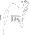
- FIG. 20 provides a picture of a balloon catheter system according to an embodiment of the invention.
- Pulsatile balloon catheter systems are provided. Aspects of the systems include: a pulse generator; and a balloon catheter assembly operably connected to the pulse generator.
- the balloon catheter assembly includes: a proximal connector operably connecting the balloon catheter assembly to the pulse generator and configured to transduce a first pulse energy generated by the pulse generator to a second pulse energy; a distal balloon; and a catheter component, where the catheter component includes a fluidic passage operably positioned between the proximal connector and the distal balloon, which passage is configured to propagate the second pulse energy from the proximal connector along the fluid passage to the distal balloon.
- robotic balloon catheter systems Also provided are balloon catheter assemblies and kits that include the same. The systems, assemblies and kits find use in a variety of different applications, including balloon angioplasty applications.
- the potential energy source acts to drive the balloon angioplasty oscillations
- a switching system controls the frequency, duty cycle, and/or amplitude of the outputted energy from the pulse generator
- a proximal connector of the balloon catheter assembly converts the outputted energy into hydraulic oscillations that thereby generate oscillations in an angioplasty balloon catheter
- the high flow balloon catheter allows the pressure oscillation inputs to the system to be achieved and optimized at the balloon output.
- the 3/2-way solenoid 470 operates in two states—an ON and OFF state.
- the valve poppet and spring assembly 474 is actuated by energizing the electromagnetic coil 473 allowing high-pressure flow from the inlet 471 to proceed to the outlet 472 and the proximal connector (not shown) to pressurize the balloon.
- the electromagnetic coil 473 is de-energized, and the valve poppet and spring assembly 474 is closed allowing the pressurized fluid from the proximal connector (not shown) to be exhausted through the inlet 472 to the exhaust port 475 .
- a noise reducer (not shown) at the exhaust port 475 may be used.
- FIGS. 4 E and 4 F provide exploded and assembled views, respectively, of an actuator 400 coupled to a proximal end connector 300 via connector 420 .
- Electrical connector 430 may be spring loaded to account for any tolerance differences or movement generated during the repeated connection and disconnection of the proximal connector.
- a mathematical model of the oscillating system is described below. This model has several purposes including for controlling the system in real-time (e.g., for a state-space controller).
- the mathematical model describes the system of FIG. 1 where a high potential source is converted to fluid pressure oscillations in the catheter and to the balloon.
- the input oscillations may be modelled as instantaneous step inputs of pressure, P input .
- the oscillations flow along a catheter with radius 2r and length l to the angioplasty balloon.
- the fluid responds rapidly to the step input, but as the balloon pressurizes, the fluid pressure gradient decays to equilibrium with the input step pressure.
- the volume-pressure relationship of the balloon determines the corresponding pressure generated in the balloon for a given volume and balloon stretch.
- the pressure gradient is treated as quasi-static and independent of time for small time steps.
- the flow through the lumen of the catheter is modeled using the Navier-Stokes equation for pipe flow:
- the contrast mixture is modeled as an incompressible fluid, so that
- the dimensionless parameters include dimensionless radial position ⁇ :
- v z 1 4 ⁇ ⁇ ⁇ d ⁇ P d ⁇ z ⁇ R 2 [ ⁇ 2 - 1 + 8 ⁇ ⁇ n J 0 ( ⁇ n ⁇ ⁇ ) ⁇ n 3 ⁇ J 1 ( ⁇ n ) ⁇ e - ⁇ n 2 ⁇ ⁇ ] ( 6 ) and the volumetric flow rate is
- a n 2 ⁇ ⁇ 2 ⁇ v ⁇ z ⁇ 0 + 8 ⁇ n 3 ⁇ J 1 ( ⁇ n ) ( 6 )
- System parameters of this model include step input characteristics, balloon dimensions, catheter construction and dimensions, pressure-volume relationship of the balloon, and the like.
- Step input characteristics are system dependent and can be measured (e.g., during the manufacturing process) and built into the system. Likewise, with various sensor measurements built into the system, the system, in certain embodiments, may be able to measure the step input response generated by the pressure generator.
- balloon dimensions and catheter construction and dimensions can be pre-loaded onto the balloon catheter memory. These dimensions include balloon length, diameter, shape, and the like. Catheter construction and dimensions include details such as the shape of the cross-section of the catheter lumen (e.g., co-axial, co-extrusion, etc.) and catheter length, outer diameter, inner diameter, ratio of flow channel area to guidewire channel area, and the like.
- the pressure-volume relationship of the balloon can be measured and pre-loaded onto the balloon catheter memory. An example of a pressure-volume relationship for an unrestrained 4 mm diameter ⁇ 20 mm length balloon is shown in FIG. 5 .
- the system may be controlled in real time (e.g., using negative feedback control and/or feedforward control) to ensure pressure amplitude, duty cycle, and frequency are appropriately set during the procedure.
- Two examples of the experimentally measured pressure in the balloon and force output from the balloon is shown in FIG. 6 .
- the model as derived above, predicts the experimental measurements accurately. With such a predictive model and with feedback from system measurements, procedural characteristics (frequency, pressure input, and duty cycle) can be adjusted to ensure maximized treatment effect.
- This pressure-volume relationship of FIG. 5 and “unconstrained balloon” of FIG. 6 represents the relationship between pressure and volume of the balloon when the balloon is not constrained by an external constraint (e.g., a hard stenosis embedded within a vessel wall).
- an external constraint e.g., a hard stenosis embedded within a vessel wall.
- this pressure-volume relationship is different.
- the curve has a steeper slope (i.e., the pressure increases with a higher rate for a smaller volume of fluid). Therefore, the pressure-volume curve is case dependent and may be steeper with more diseased tissue. Because this curve is case dependent, the pressure-volume curve must be generated on a case-by-case basis inside the patient (i.e., in-situ) and during treatment.
- both the pressure and the volume in the system can be measured in-situ with varying inputs to the system.
- the pressure in the balloon may be increased to known values while the volume in the balloon (e.g., using the described positional sensor) is measured to generate the in-situ pressure-volume curve (CYCLE 1 of FIG. 7 ).
- this treatment-based pressure-volume curve may be compared to the unconstrained pressure-volume curve, which in some cases is an indication of a successful treatment, or to curves measured during the treatment progression (CYCLE 1000 or CYCLE 10000 of FIG. 7 ).
- Comparing the pressure-volume curves in this way can be used to provide a repeatable measure of outcome, e.g., treatment success, insufficient balloon diameter, balloon under-expansion, and the like even during pulsatile balloon angioplasty.
- outcome e.g., treatment success, insufficient balloon diameter, balloon under-expansion, and the like even during pulsatile balloon angioplasty.
- the system may incrementally increase the pressure within a safe range until the balloon volume increases.
- the system may provide feedback (audio, visual, feel, and the like) to the operator to indicate the pressure amplitude of the pulses is not high enough.
- the system is configured to detect single-plane under-expansion, an example of which is shown in FIG. 7 B (Panels A-D).
- FIG. 7 B (Panels A-B) show a fluoroscopy image of a focal lesion, which is restricting blood flow.
- standard BA is performed by inserting the balloon across the lesion and increasing the pressure in the balloon.
- the balloon expands as shown in FIG. 7 B (Panel C).
- the balloon remains under-expanded, which could be missed by the physician.
- the system can measure when the balloon is under-expanded without requiring multiple projection fluoroscopy images. This benefit reduces procedural time, radiation exposure to the physician and patient, and injected contrast.
- vessel compliance is a measurable characteristic of blood vessels calculated based on a ratio of the change in vessel volume for a given change in pressure.
- Vessel compliance is an important characteristic for observation because improving vessel compliance is a prerequisite to definitive treatment of certain underlying blood vessel disease conditions, such as atherosclerosis. Changes in vessel compliance are seen in the different pressure-volume curves depicted in FIG. 7 A , described above.
- the pressure-volume, i.e., vessel compliance, characteristic of a treated vessel changes as a result of treatment from CYCLE 1 to CYCLE 1000 to CYCLE 10000.
- Systems according to the present invention may be configured to assess vessel compliance by obtaining measurements in-vivo of changes in volume at different pressures (or changes in pressure) applied to vessels.
- FIG. 7 C provides an example of measurements of changes in vessel compliance obtained during treatment using a system according to the present invention.
- embodiments of the present invention enable measurement of relative compliance change of the luminal tissue (i.e., a vessel) in real time during application of a system of the present invention to provide pulsatile intravascular lithotripsy treatment.
- Systems of the present invention may be configured to measure, and update, treatment parameters based on compliance change of the vessel.
- the luminal tissue i.e., a vessel
- balloon may expand significantly, contributing to a large gain in compliance, as measured by the system.
- changes in compliance, as measured by the system may subside. Identification of such conditions may indicate that treatment may be halted because no further appreciable luminal gain is occurring.
- Systems may be configured to measure pressure in any convenient manner.
- embodiments of systems according to the present invention may comprise a pressure gauge as described herein for measuring pressure in, for example, fluid passages and distal balloon of a balloon catheter assembly, including, for example, balloon catheter assemblies according to the present invention.
- a pressure gauge may be installed such that it is configured to measure pressures of a distal chamber of a proximal connector, as seen, for example, in pressure transducer 325 in FIG. 3 A .
- Systems may be configured to measure changes in volume of a vessel in any convenient manner.
- embodiments of systems according to the present invention may be configured such that changes in the position of a membrane separating proximal and distal chambers of the proximal connector reflect changes in volume of the distal balloon. Changes in the volume of the distal balloon reflect changes in the cross-sectional area of a vessel and therefore changes in volume of the vessel.
- Such embodiments may further comprise a Hall sensor and a permanent magnet for measuring changes in the position of such a membrane.
- a Hall sensor refers to a sensor configured to sense the presence of, or changes in, a magnetic field, i.e., by use of the Hall Effect.
- a permanent magnet may be comprised of any convenient magnetic material, or an electromagnet, as desired, such that relative changes in position of the Hall sensor with respect to the permanent magnet are detected by the Hall sensor. Sensors such as the Hall sensor and permanent magnet described above may be used to measure the change in volume of the distal balloon as well as the rate at which the distal balloon inflates, i.e., the rate of vessel volume change.
- FIG. 8 depicts the system according to an embodiment of the present invention shown in FIG. 1 , further configured to assess vessel compliance according to an embodiment of the present invention. Elements of the system shown in FIG. 8 that are identical to those shown in FIG. 1 are described above in connection with FIG. 1 .
- Hall sensor 805 is positioned on membrane 30 such that changes in position of membrane 30 relative to permanent magnet 810 positioned on proximal connector 400 trigger changes in output of Hall sensor 805 . Such changes in output of Hall sensor 805 are indicative of changes in volume of distal balloon 3 .
- pressure or flow transducer 31 is configured to measure pressure applied to catheter 16 and balloon 2 .
- Measurements of changes in volume based on Hall sensor 805 and permanent magnet 810 and changes in pressure based on pressure gauge 31 are used to measure vessel compliance in-vivo. Such measurements of vessel compliance can be taken during treatment. Such measurements are used to develop pressure-volume curves 815 showing the pressure-volume relationship at a treatment stage. Pressure-volume curves 815 can be generated at different stages of treatment and may be used to assess treatment effectiveness, compare treatment across different settings or to revise or otherwise adjust treatment in order to optimize the effectiveness of treatment. In embodiments, pressure-volume curves 815 may resemble those set forth in, for example, FIG. 7 A , described above, or FIG. 17 , described below.
- the data used from these pressure volume curves can be gathered and batched and eventually used to predict (i) success or failure of therapy, (ii) a need to adjust or attenuate energy used in future treatments of populations or similar vessels, (iii) complicating conditions, such as circumferential calcium versus 270 degrees of calcium or (iv) the location of areas in the arterial anatomy that are relatively fixed or those exposed to significant torsion or flexion. While the exemplary embodiment for measuring vessel compliance according to the present invention is shown in FIG. 8 in the context of the system described in connection with FIG. 1 , it is to be understood that the technique for measuring vessel compliance according to the present invention is not so limited and may be applied to other balloon-based systems such as those indicated in 820 of FIG.
- ⁇ 8 such as, for example, laser-based techniques, ultrasound-based techniques, pulsatile balloon-based techniques, such as those described herein, or plain balloon angioplasty-based techniques.
- data collected upon application of the system e.g., in connection with treatment, such as pressure-volume data as described above, may be used to apply various algorithms for machine learning.
- Such machine learning applications may be trained to make predictions such as those described above, e.g., regarding the success or failure of a treatment, a need to change aspects of the treatment, such as energy applied, the presence of complicating conditions or aspects of the underlying anatomy of a subject or population of subjects.
- machine learning techniques of interest may include artificial neural networks, including convolutional neural networks or other methods of applying deep learning techniques, decision trees, support vector machines, regression analysis, Bayesian networks or genetic algorithms.
- Machine learning techniques of interest may be implemented in software such that they can be executed on a general-purpose processor, such as commercially available general-purpose processors, or a special purposes processor, such as graphics processors, such as commercially available graphics processors, or may be implemented on dedicated hardware.
- FIG. 9 A depicts an isometric view of proximal connector 900 according to an embodiment of the present invention configured for measuring vessel compliance
- FIG. 9 B depicts a cutaway view of proximal connector 900
- Proximal connector 900 includes proximal flange 910 and distal flange 915 separated by membrane 920 .
- Proximal flange 910 defines proximal chamber 925 which is accessed by proximal port 930 .
- Distal flange 915 defines a distal chamber 935 which is accessed by distal port 940 .
- Pressure transducer 945 is operably coupled to distal port 940 and distal chamber 935 defined by distal flange 915 .
- Pressure transducer 945 is configured to observe changes in pressure applied to a distal balloon connected via distal flange 915 .
- Permanent magnet 950 is connected to proximal flange 910 and is configured to remain in a fixed position relative movement of membrane 920 .
- Hall sensor 955 affixed to membrane 920 is configured to move with membrane 920 relative to permanent magnet 950 enabling observation and measurement of changes in volume of a distal balloon.
- Distance 955 represents the furthest left position (X l ) that membrane 920 can travel within proximal chamber 925 .
- Distance 960 represents the furthest right position (X r ) that membrane 920 can travel within distal chamber 935 .
- Distance 960 represents the position (x) of membrane 920 depicted in FIG. 9 B .
- Hall sensor 955 and permanent magnet 950 are configured to sense changes in membrane 920 position between leftmost distance 955 and rightmost position 960 .
- FIG. 10 depicts a plot 1005 of the calculated, i.e., analytical, output of a Hall sensor affixed to a membrane, such as the configuration of Hall sensor 955 and permanent magnet 950 in the schematic shown in FIGS. 9 A and 9 B , and a plot 1010 of experimental results confirming the analytical results of plot 1005 .
- the analytical calculation for the magnetic flux density, B i.e., the magnitude of the effect of the magnetic field, along the symmetry axis of a permanent, axially magnetized ring magnet such as in the configuration of permanent magnet 950 in the schematic shown in FIGS. 9 A and 9 B is:
- B B r 2 [ D + z R a 2 + ( D + z ) 2 - z R a 2 + z 2 - ( D + z R i 2 + ( D + z ) 2 - z R i 2 + z 2 ) ]
- B r is the remanence field of the magnet independent of the magnet's geometry
- z is the distance from a pole face on the magnet's axis
- D is the thickness of the ring
- R a is the outside radius of the ring
- R i is the inside radius of the ring.
- the magnitude of the magnetic flux density induces a measurable voltage change in the Hall Effect sensor depending on the distance, z, of the Hall effect sensor from the permanent magnet.
- the x-axis 1015 of plot 1005 indicates distance of a membrane from a reference position (i.e., position of a permanent magnet), such as membrane distances 955 , 960 and 965 in FIG. 9 B .
- the y-axis 1020 of plot 1005 relates to the magnetic flux density, i.e., the magnitude of the effect of the magnetic field, associated with a permanent magnet at different distances from the permanent magnet.
- Plot 1005 depicts the leftmost possible membrane position at position 1025 , and the rightmost possible membrane position at position 1030 (where “right” and “left” refer to membrane positions seen in FIG. 9 B , described above). Analytical results of the effect of the magnetic field versus distance from the permanent magnet are shown on curve 1035 .
- the x-axis 1037 of plot 1010 represents changes in volume of a distal balloon based on different membrane positions.
- the y-axis 1040 of plot 1010 represents voltage levels generated by a Hall sensor as the Hall sensor travels different distances from a permanent magnet.
- Curve 1045 reflects voltage data collected from a Hall sensor such as, for example, the configuration of membrane-mounted Hall sensor and permanent magnet shown in FIGS. 9 A and 9 B .
- Curve 1045 indicates a different voltage value for each balloon volume value shown on x-axis 1037 (associated with different membrane positions or distances between the membrane and a permanent magnet). That is, each membrane position, and therefore balloon volume, results in a different voltage level generated by the Hall sensor.
- curve 1045 provides a unique solution such that each voltage corresponds to a different membrane position (diaphragm distance from the permanent magnet), which relates to balloon volume.
- the largest change in measured voltage (plotted on y-axis 1040 of plot 1010 ) occurs between volume displacement measurements of approximately 0 mL and approximately 2.75 mL, allowing for precise volume measurements through an operating region of interest, i.e., balloon volumes between 0 mL and 2.75 mL.
- measurements of changes in vessel volume in combination with changes in vessel pressure can be used to assess vessel compliance.
- Use of the systems and techniques described herein allow for assessment of vessel compliance in-vivo and during treatment.
- Changes in vessel compliance including changes during treatment or pre- and post-treatment may be used to assess treatment efficacy and/or to adjust vessel treatment.
- changes in vessel compliance may be used to adjust therapeutic intensity and/or duration.
- Understanding and collection of data related to treatment such as measurements of vessel volume and pressure, can be used for future predictive algorithms such that therapy is administered at varying frequencies and/or oscillations to reduce the time necessary for treatment and to more accurately predict the energy required prior to administering therapy.
- Such aspects of a treatment e.g., frequency of the system and/or oscillations, may be adjusted by the operator, or in other cases, may be automatically adjusted based on, for example, machine learning and/or other predictive algorithms, as described herein.
- Balloon angioplasty systems such as, for example, pulsatile balloon catheter systems according to the present invention, may benefit from being configured to monitor for safe and effective operation of the system.
- Systems according to the present invention may be configured to monitor one or more measurable characteristics to ensure safe and effective operation and treatment.
- an output pulse of energy should correspond to an expected value, such as an input pulse of energy or a threshold amplitude of an energy pulse.
- Such embodiments may be configured to measure, or to compare, or to otherwise monitor, output pulses of energy to ensure compliance.
- the input pressure applied to the system should correspond to the peak pressure measured in the system.
- system states may be determined by configuring the system to compare a measured characteristic of the system, e.g., catheter pressure, such as peak catheter pressure, or distal balloon volume, to an expected threshold, i.e., target pressure or target volume, or minimum or maximum expected values thereof.
- catheter pressure may be measured using any convenient pressure sensor, such as, for example, a pressure gauge, as described above.
- a pressure sensor may be integrated into a distal chamber of a proximal connector of an embodiment of a system according to the present invention.
- the pressure sensor may be configured to measure pressure applied to a distal balloon, by, for example, measuring fluid pressure in the distal chamber in fluidic communication with a distal balloon.
- Distal balloon volume may be measured using any convenient sensor, such as, for example, a membrane positional sensor or displacement sensor or other sensor, such as those described herein, configured to measure changes in volume of the distal balloon.
- the membrane positional sensor is a Hall sensor and a magnet present at a fixed location of the membrane of the proximal connector configured to measure changes in volume corresponding to the distal balloon, as described above.
- an electronic circuit may be configured to determine system states.
- a sensor configured to measure a system characteristic such as those described herein, may be further configured to output an electronic signal based on the measured characteristic.
- a sensor configured to measure a system characteristic such as a pressure sensor configured to measure system pressure or a membrane positional sensor configured to measure distal balloon volume, may be further configured to output an electronic signal based on the measured characteristic, such as measured pressure or measured volume.
- the measured signal may be compared to a target threshold, such as a target pressure or target volume, using a comparator circuit to compare the measured system characteristic to a reference voltage corresponding to a target threshold.
- a comparator circuit capable of comparing the difference between characteristics of signals, such as comparing signal voltage or current, and producing a digital (i.e., binary) output indicating the result of the comparison, e.g., which signal is larger, may be applied.
- the comparator circuit may be an analog comparator circuit, such as a differential amplifier, for example, a high-gain differential amplifier.
- the comparator circuit may be a digital circuit, such as an adder circuit or a more complex or more specialized digital logic circuit.
- the signal corresponding to the measured system characteristic such as a measured pressure or a measured volume
- a target value or threshold such as a target pressure or target volume.
- the result of the summation may then be applied to a comparator circuit for comparison against a threshold where the threshold represents a tolerance or expected difference between the measured system characteristic and a target threshold (e.g., measured pressure and a target pressure or measured volume and a target volume).
- Such a configuration where the difference between the measured system characteristic and a target value of the system characteristic (e.g., measured pressure and a target pressure or measured volume and a target volume) is compared to a threshold, may allow for a buffer around the expected system characteristic, which in some cases, may account for noise or other signals that are not representative of system state.
- a target value of the system characteristic e.g., measured pressure and a target pressure or measured volume and a target volume
- the result of the comparator circuit may be (or in some cases may be converted to) a digital signal, where the logical value of the digital signal indicates whether the measured system characteristic (such as measured pressure or measured volume) is an expected or unexpected reading.
- the circuit may be configured such that the comparator produces a digital high signal, i.e., a logical 1, when the measured system characteristic (e.g., measured pressure or measured volume) falls outside of an expected range and a digital low signal, i.e., a logical 0, when the measured system characteristic falls within an expected range.
- a digital signal may be stored in a memory. Any convenient electronic circuit capable of storing a digital logic signal may be applied.
- the memory may consist of a flip-flop circuit, for example a flip-flop capable of storing a single bit.
- the output value of the flip-flop reflects system state.
- the output of the flip-flop may indicate a logical 0 when the system state is normal and a logical 1 when the system state is in a fault state.
- Such an output of the flip-flop may be treated as an alarm signal such that when the alarm signal is raised, continued use of the system may be unsafe or ineffective.
- Such signal may be conveyed to an operator of the system in any convenient manner.
- system state may be conveyed to the operator through a warning signal such as a warning light or sound or vibration.
- system state may cause the system to automatically take an action, such as automatically turning off aspects of the system.
- the system state value stored in memory e.g., the value stored in the flip-flop, to reflect a comparison of the maximum or minimum of the measured system characteristic, such as a comparison of the measured pressure at peak amplitude of the measured pressure or a comparison of the measured distal balloon volume at peak amplitude of the measured volume. That is, in embodiments, the system state reflects peak catheter pressure or peak distal balloon volume.
- This digital data can be used for understanding population and anatomic variables and the pressures and energy needed as well as in connection with machine learning techniques, such as, for example, training data for machine learning models, to predict the energy needed and best therapeutic energy to apply.
- system state may reflect whether the peak measurement of a system characteristic rises to or above a target measurement value of the system characteristic, e.g., whether the peak amplitude of the measured pressure or measured distal balloon volume rises to or above a target pressure or volume, respectively, at an expected time.
- a target measurement value of the system characteristic e.g., whether the peak amplitude of the measured pressure or measured distal balloon volume rises to or above a target pressure or volume, respectively, at an expected time.
- an unexpected pressure drop for example, may be indicated.
- the system may be configured to continuously monitor a system characteristic, such as catheter pressure or distal balloon volume, and continuously compare such measurement against target value.
- the system in order for the output state of the flip-flop to accurately reflect system state, the system may be configured such that the result of the comparator circuit is written to the flip-flop at a time corresponding to the time when the catheter is expected to be exposed to a peak measurement value, e.g., peak pressure or peak volume. That is, the flip-flop write operation is coordinated with the time the system is expected to exhibit a peak measurement value, e.g., peak pressure or peak volume. Any convenient technique to synchronize sensor readings at the appropriate time may be applied. In some cases, the flip flop write operation may be synchronized by setting the flip-flop clock signal to an inverted control signal used to control input pressure to the catheter.
- a peak measurement value e.g., peak pressure or peak volume
- the leading edge of the flip flop clock signal corresponds to the time that the control signal turns off pressure to the catheter, which in turn corresponds to a time that pressure has been applied to the catheter the longest, i.e., peak catheter pressure.
- the leading edge of the flip flop clock signal corresponds to the time that the control signal turns off pressure to the catheter, which in turn corresponds to a time that pressure has been applied to the catheter the longest, i.e., peak catheter pressure.
- system state reflected in the logical value of the memory device i.e., flip-flop
- the peak value of the measured system characteristic e.g., peak pressure or peak volume.
- system state may indicate that the system fails to reach a peak measurement value at any time during pulsatile cycle of applying and then removing pressure to the distal balloon and therefore the system is not functioning safely or effectively or otherwise as expected.
- FIG. 11 presents a circuit diagram of an exemplary electronic circuit 1102 for monitoring system state via catheter pressure according to aspects of the present invention. While the diagram shown in FIG. 11 relates to measuring catheter pressure, those skilled in the field will understand that similar configurations may be employed to measure other system characteristics, such as, for example, distal balloon volume. As seen in FIG. 11 , measured pressure 1105 is an input signal to circuit 1102 . As described herein, the measure pressure signal may be an analog or digital signal ultimately generated by a pressure sensor attached to the embodiment of the system and used to measure energy applied to the system, such as catheter pressure. Target pressure 1110 is another electronic signal that is an input signal to circuit 1102 .
- Target pressure signal 1110 may be hardwired to a specified value or may be configurable based on different types of distal balloons, different types of treatment strategies, including the amount of pressure expected to be applied to the catheter. Measured pressure 1105 and target pressure 1110 are routed to a summation circuit 1115 configured to compute the difference between measured pressure 1105 and target pressure 1110 . That is, in the embodiment depicted in FIG. 11 , summation circuit 1115 is configured to add target pressure 1110 to a negative value of measured pressure 1105 .
- Summation result 1120 of summation circuit 1115 is compared against threshold value 1125 .
- Summation result 1120 and threshold value 1125 are both inputs to comparator circuit 1130 .
- Threshold value 1125 is an input signal to circuit 1102 and may be a hardwired value or may be a configurable value that in either case reflects acceptable tolerance between measured pressure 1105 and target pressure 1110 .
- Comparator circuit 1130 is configured to produce a comparator result 1135 that is a digital low value, i.e., logical 0, if the result of the comparator circuit 1130 is within an allowable tolerance and to produce a digital high value, i.e., logical 1, if the result of the comparator circuit 1130 is outside an allowable tolerance.
- Comparator result 1135 is connected to the data-in port of flip-flop 1140 , used to store system state, in this case in the form of a one-bit digital logic value.
- Solenoid trigger signal 1145 is a pressure control signal used to control a solenoid that turns on pressure to a catheter. That is, when solenoid trigger signal 1145 is high, the solenoid is controlled such that pressure is input into the catheter (not shown in FIG. 11 ) and therefore applied to the distal balloon (not shown in FIG. 11 ). When embodiments are configured as such, pressure will have been applied to the catheter for the longest amount of time upon the trailing edge (i.e., falling edge) of solenoid trigger signal 1145 . Because the catheter will have been exposed to pressure for the longest time upon the trailing edge of solenoid trigger signal 1145 , catheter pressure is expected to be at its peak amplitude at that time. That is, maximum catheter pressure is expected upon each trailing edge of solenoid trigger signal 1145 .
- solenoid trigger signal 1145 Prior to being routed to the flip-flop clock input signal, solenoid trigger signal 1145 is inverted using inverter 1150 . Any convenient inverter circuit or digital logic NOT gate may be applied to cause inverter output 1155 to logically reflect an inverted solenoid trigger signal 1145 , such that, for example, leading edge 1170 of inverter output 1155 corresponds to trailing edge 1160 of solenoid trigger signal 1145 and falling edge 1175 of inverter output 1155 corresponds to leading edge 1165 of solenoid trigger signal.
- flip-flop 1140 is a positive-edge triggered flip-flop, i.e., it is configured such that the stored value is written upon each leading edge of the flip-flop clock signal
- comparator result 1135 will be written to flip-flop 1140 upon each trailing edge of solenoid trigger signal 1145 .
- comparator result 1135 reflects a comparison of measured pressure 1105 at the peak amplitude of pressure applied to the distal balloon through the catheter.
- flip-flop output signal 1180 reflects system state.
- electronic circuit 1102 is configured so that flip-flop output signal 1180 is a digital low or logical 0 value meaning measured pressure appears to be within an acceptable threshold of target pressure and no unexpected pressure drop is detected.
- electronic circuit 1102 is configured so that flip-flop output signal 1180 is a digital high or logical 1 value meaning measured pressure appears to be outside an acceptable threshold of target pressure and an unexpected pressure drop has been detected.
- Plot 1205 shows normal system operation during time period 1240 , between approximately time 0 and 0.4 seconds.
- peak measured pressures consistently rise nearly to target pressure 1225 and is consistently within the acceptable threshold 1230 of target pressure 1225 .
- catheter pressure is consistently within an acceptable pressure range during this time, the electronic circuit configured to monitor system state consistently indicates normal system operation. This result is reflected in system state signal 1235 remaining at logical 0 during time period 1240 .
- plot 1205 Also shown on plot 1205 is a period of system fault during time period 1245 , between approximately 0.4 seconds and 1 second.
- time period 1245 peak measured pressures consistently fail to rise to target pressure 1225 and are consistently outside of the acceptable threshold 1230 of target pressure 1225 .
- peak catheter pressure is consistently outside the acceptable pressure range during this time, the electronic circuit configured to monitor system state consistently indicates a system fault due to the measured pressure drop. This result is reflected in system state signal 1235 rising to and remaining at logical 1 during time period 1245 .
- Systems according to the present invention may be configured to detect whether a catheter is an intact catheter, whether the catheter has completely failed or whether the catheter has a leak.
- FIG. 12 B depicts example behavior of pressure and volume measurements from an intact (i.e., not leaking) catheter of a system according to the present invention during treatment.
- the peak and trough pressures remain substantially the same throughout treatment and the volume over the treatment does not decline.
- FIG. 12 C depicts example behavior of pressure and volume measurements from a completely failed catheter of a system according to the present invention during treatment.
- a completely failed catheter can cause damage to the lumen and can cause damage to the amplifier assembly.
- a burst catheter may be detected within less than 0.05-2 seconds such as 0.1 seconds of treatment.
- the volume sensor measures a drop in volume, which triggers a system warning and stops the treatment. Volume decrease may be in the range of 0.01 to 10 mL/sec such as 0.5 mL/sec. Peak pressure also decreases during the burst but lags the volume change.
- FIG. 12 D depicts example behavior of pressure and volume measurements from a leaking catheter of a system according to the present invention during treatment.
- a leaking catheter can cause a jet of fluid that damages the vessel wall.
- the leaking of the catheter can be detected by measuring an increase in trough pressure during the pressure cycle along with a decreasing volume in the catheter.
- Trough pressure increase may be in the range between 0.1-10 atm such as 1-2 atm.
- Volume decrease may be in the range of 0.01 to 10 mL/sec such as 0.1 mL/sec.
- a software-based scheme may be used to detect the combination of these conditions to immediately shut off the system during pulsatile intravascular lithotripsy therapy.
- FIG. 13 provides a schematic of an alternative connector 1300 configured to deliver a high-volume, low-frequency and low-pressure pulse (i.e., pulsatile energy).
- Connector 1300 comprises barrel syringe 1310 with plunger (i.e., piston) 1320 separating pneumatic chamber 1330 from fluid chamber 1340 .
- Pneumatic chamber 1330 comprises pneumatic input port 1370 , configured to receive energy (i.e., a first pulse energy) from the manifold assembly (not shown), e.g., in the form of pneumatic pressure, and transmit such energy to pneumatic chamber 1330 .
- Plunger 1320 is configured to translate in response to pressure applied to pneumatic chamber 1330 , in turn transmitting energy to fluid chamber 1340 .
- Fluid chamber 1340 comprises fluid output port 1350 operably connected to a catheter (not shown) and configured transmit energy to catheter (i.e., a fluidic chamber thereof) in response to movement of plunger 1320 compressing fluid chamber 1340 .
- Connector 1300 further comprises biasing spring 1360 configured to urge plunger 1320 to return to a starting position when plunger 1320 is displaced.
- a connector comprises an internal fluid
- the connector may be configured to receive fluid through a fluidly coupled priming port (not shown).
- a fluid port may be connected to fluid chamber 1340 in connector 1300 of FIG. 13 .
- a fluid such as radiopaque contrast, saline, CO 2 or the like may be injected to prime the fluid chamber.
- a vacuum may be applied to such a port so that the connector as well as the system as a whole can be, for example, de-gassed prior to treatment.
- the priming port may be closed and sealed so that no fluid may exit the port during treatment.
- Systems of the invention find use in a variety of applications. In some instances, the systems find use in fracturing hardened materials embedded within an elastic conduit.
- the present disclosure describes applications related to treating atherosclerotic calcifications within an arterial conduit, such as a coronary or peripheral artery.
- the present system and teachings are not solely limited to atherosclerotic calcifications nor arterial conduits and may be generally applied to other applications as determined by those skilled in the art. For example, this is especially true for circumstances that alter arterial compliance (vessel compliance, as described above, of an artery) or for cases that involve medical interventions, such as the presence of a previous stent with subsequent blockage.
- the compliance of the vessel is altered by the intra-luminal placement of a previous stent. Data and feedback of vessel compliance curves can be used in connection with future therapies as well as for prediction techniques, such as machine learning techniques described herein.
- DBA dynamic balloon angioplasty
- a technique that uses pressure oscillations with a generalized waveform in some embodiments, harmonic, or frequency-specific, pressure waveform oscillations
- FIGS. 14 A- 14 E The concept of DBA for treating arterial calcified plaque is illustrated in FIGS. 14 A- 14 E .
- a catheter 16 with balloon 2 is deployed to the vessel 1400 with calcification 1450 ( FIG. 14 B ), e.g., with the assistance of a guidewire using any convenient protocol, such as those known in the art.
- the plaque is subjected to high-frequency pressure oscillations ( FIGS.
- the cyclic loading described in FIGS. 14 A- 14 E causes cyclic stresses at these sharp corners near plaque microfractures and irregular surfaces.
- the cyclic stress initiates and grows these sharp corners, which expand the microfractures into larger macroscopic fractures.
- the growth of these microfractures leads to the more complete fracture of plaque at lower inflation pressures compared to static pressure. Higher frequency pressure cycles and higher-pressure differences between the cycles is expected to increase the effectiveness of this crack growth mechanism.
- DBA lowers the required balloon pressure for fracturing calcified plaque (e.g., in some instances between 1 to 50%, such as 20 to 30%, as compared to a suitable non-DBA control), improves stent deployment, improves and controls drug delivery for drug-coated balloons, stress-softens soft, lipid-core atheromatous plaques, expands calcified in-stent restenoses, and fracture calcifications on diseased cardiac valve leaflets and improves balloon-based expansion and deployment of prosthesis and devices. Further details regarding embodiments of DBA methods in which the systems described herein may be employed are provided in United States Published Patent Application Publication No. 20200046949 as well as pending PCT Application Serial No. PCT/US2020/055458; the disclosures of which are herein incorporated by reference.
- systems of the invention e.g., as described above, are employed in a manner sufficient to achieve a four-part pulsatile treatment plan, e.g., as illustrated in FIG. 15 , which four-part pulsatile treatment plan provides for safe, controlled expansion of hardened plaques and surrounding healthy soft tissues.
- a four-part treatment algorithm may be employed, which four-part treatment algorithm includes the following steps: (1) soft-tissue low-stress expansion phase 3800 via Mullins' Effect; (2) plastic deformation phase 3700 in the calcified plaque until plaque fracture; (3) plaque fracture detection and immediate reduction in pressure phase 3600 to reduce surrounding tissue stress; and (4) soft-tissue low-stress expansion phase 3500 via Mullins' Effect to expand soft-tissue post-calcium fracture.
- An embodiment in which the force applied to the vessel over time by this four-part algorithm is illustrated in FIG. 6 . Because of the significant attenuation across the catheter and the lack of pressure control in prior art approaches, the input pressure to the catheter is not successfully transmitted to the balloon (the system output).
- tissue stress in prior art systems is not returned to a low state (i.e., there is no tissue relaxation period) during high frequency oscillation, which limits the effect of Mullins' stress cycling.
- the present system induces pressure oscillations in the balloon (the system output) that follows the pressure input from the proximal source with pressure oscillations between 0-50 ATM, frequencies between 0-25 Hz, and duty cycles between 60-80%.
- This advancement is important for two reasons: (1) it allows the tissue to relax during the depressurization cycle (following the Mullins' Effect) and (2) it allows sufficient oscillations to be applied to the vessel within the limited time during which an artery is occluded during treatment. Further details regarding methods in which embodiments of the invention may be used are found in pending PCT application serial no. PCT/US2020/055458; the disclosure of which is herein incorporated by reference.
- embodiments of the present invention may be applied to assess vessel compliance.
- Blood vessels are naturally compliant, elastic structures. Their compliance is required to convert the pulsatile flow from the heart into steady flow in the capillaries. Over time, however, the aging and atherosclerotic process can diminish the compliance of vessels and reduce lumen area, creating flow mismatches and additional stress to the vascular system. Vessel compliance is especially diminished during and after the formation of intimal and medial calcified plaque in the vessel wall.
- embodiments of the present invention may be used to apply pulsatile intravascular lithotripsy enabling both for cracking of calcium (i.e., cracking CP tissue as shown in FIG. 14 ) as well as to apply a final post-dilatation of the vessel.
- embodiments of the present invention may apply both applications, cracking CP tissue and applying a final post-dilation of the tissue, in a single treatment. That is, embodiments of the present invention can also be used to apply DBA first to apply pulses to a vessel to crack CP tissue and then to subsequently expand the vessel using, for example, a traditional, non-compliant balloon post-dilatation.
- vessel compliance it is meant a measurable quantity defined by the following relationship:
- ⁇ V the change in vessel volume for a given change in pressure ⁇ P. Because of tissue incompressibility, vessel volume can be converted to area by dividing by vessel length. Since the pressure-volume relationship in an artery is non-linear, compliance is often defined at a given pressure or volume.
- Vessel compliance can be difficult to obtain because simultaneous in-vivo measurements of pressure change, ⁇ P, and vessel cross-sectional area or volume change, ⁇ A or ⁇ V, respectively, may be challenging.
- Systems according to the present invention find use in addressing this difficulty by accurately assessing vessel compliance in-vivo as described below.
- the proximal connector of the catheter balloon assembly may include a membrane positional sensor, such as a Hall sensor, which provides data regarding the spatial position of the membrane at any given time, as well as a pressure gauge for measuring pressure in the liquid passages and distal balloon of the balloon catheter assembly.
- a membrane positional sensor such as a Hall sensor
- the systems may be employed to assess volume expansion of the balloon in real time, and/or vessel compliance at the site of the balloon.
- the change in volume in the balloon can be assessed in real time and the corresponding balloon pressure can be measured. That is, the system is configured to pressurize the balloon-based catheter while simultaneously reading pressure and volume in the catheter system.
- This volume-pressure relationship can provide a measure of vessel compliance, since, as described above, vessel compliance is the ratio of a change of vessel volume to a change in pressure.
- the balloon volume-pressure relationship can be measured when the balloon is uninhibited by a surrounding vessel. When located within a stiff vessel, the balloon requires a higher pressure for the equivalent balloon volume in its uninhibited, baseline state. Therefore, the balloon may be used to measure compliance of the vessel.
- the compliance of the vessel can be measured easily in-vivo.
- This compliance measure can be used as a measure of a successful treatment with a lower compliance indicating adequate or therapeutic balloon expansion and a successful treatment.
- the system is employed in methods analogous to those described in U.S. Published Application Publication No. 20150080747 (the disclosure of which is herein incorporated by reference), where membrane displacement is used as the measure of balloon volume.
- Systems and methods for measuring vessel compliance according to the present invention may be configured to obtain pre-, during, and post-treatment pressure-volume measurements. Using the data obtained during these measurements, change in vessel compliance can be obtained to determine treatment efficacy. Change in vessel compliance may also be used to adjust therapeutic intensity and/or duration.
- embodiments of the present invention may be used to generate pressure-volume (i.e., compliance curves) at various instances during treatment.
- a relative change in compliance pre- and post-treatment may be obtained. These changes may be compared amongst similar vessel segments to understand an appropriate level of compliance change.
- methods according to the present invention may also comprise obtaining concomitant measures of intraarterial cross-section using other available measuring techniques such as ultrasound, cineangiography, computed tomography, intravascular ultrasound (IVUS), and/or optical coherence tomography (OCT).
- systems according to the present invention may be configured to incorporate information obtained from such measurements, i.e., sensor fusion techniques. Volume and/or area measurements obtained through such visualization techniques may be combined with pressure and volume readings of embodiments of a balloon system according to the present invention (i.e., measurements of changes or relative volume and/or pressure) to generate absolute compliance measurements of vessels with increased accuracy. Such absolute compliance measurements may then be used to compare treatments across vascular beds for optimizing treatments for both short- and long-term success.
- an absolute measure of the compliance curve of a vessel may be obtained and compared across treatment groups.
- While systems and methods of measuring vessel compliance have been described in the context of pulsatile balloon catheter systems according to the present invention, such systems and methods for measuring vessel compliance may be applied to other systems as well, such as systems configured to deliver static balloon angioplasty, pulsatile intravascular lithotripsy, cavitation-based intravascular lithotripsy, and/or externally-applied lithotripsy pulses.
- FIG. 16 shows the procedural steps of an autonomous angioplasty procedure performed with the embodiments described above.
- the physician or technician in the sterile field may connect the proximal connector to the actuator of the embodied system. This step may involve some human interaction with the patient but, fluoroscopy may be paused to minimize operator exposure.
- a robotic catheterization device (such as those known in the art may) be used to insert the angioplasty balloon across the lesion. This step may include fluoroscopy imaging and radiation but can be performed from within a shielded lab, eliminating operator radiation exposure. Once the appropriate balloon is across the lesion, the operator may choose the appropriate treatment setting and then initiate the treatment.
- the operator may visualize the fluoroscopy images and compare those images with the measure pressure-volume data. If the treatment is not successful, the procedure may be continued with the same or different settings. If the treatment is unsuccessful, the balloon catheter may be removed robotically. During these steps, the operator may remain inside the shielded lab and protected from radiation. In some instances, the pre-filled and/or spring-biased balloon catheter and/or a composite balloon may be used to minimize radiation exposure of the operator. In these instances, the operator does not have to fill the catheter with contrast solution, nor does s/he have to remove and collapse the balloon on procedure completion. Once all of these steps are performed and fluoroscopy is no longer needed, the procedure may be finalized.
- FIG. 17 shows a graphical user interface (GUI) that the operator may interface with during the autonomous angioplasty procedure.
- GUI graphical user interface
- the GUI may have several information zones such as a Treatment Characteristics zone, Balloon Characteristics zone, and Plotting zone.
- the Treatment Characteristics zone indicates the important procedural characteristics that the operator employs during the procedure. Such characteristics include pressure, frequency, duty cycle, cycle number, and procedure time. Some or all of these characteristics may be updated or changed by the system and/or by the user.
- the Balloon Characteristics zone may include information regarding the balloon that has been attached to the handheld actuator. Information that may be displayed includes balloon diameter, length, nominal pressure, and rated pressure, and other balloon characteristics, such as drug-coated or stent covered balloons.
- balloon catheter connectivity information (i.e., whether a balloon has been connected or not) can be included in this section.
- various procedural plots may be displayed including a compliance plot and treatment plot.
- the compliance plot may include a nominal pressure-volume curve that may be provided with the balloon. Additionally, a pressure-volume curve measured in-situ during the procedure may be plotted and updated throughout the procedure. The operator may use this plot to determine treatment effect as a measure of compliance or efficacy.
- the pressure plot may include a display of pressure versus time.
- Other information that may be included (not shown) on the GUI include treatment status and intensity, ON/OFF switches, indicator LEDs, and the like.
- the systems may be used to apply pulsatile energy to internal tissue locations of any number of different subjects.
- the subjects are “mammals” or “mammalian,” where these terms are used broadly to describe organisms which are within the class mammalia, including the orders carnivore (e.g., dogs and cats), rodentia (e.g., mice, guinea pigs, and rats), and primates (e.g., humans, chimpanzees, and monkeys).
- the subjects are humans.
- kits that include systems, or one or more components thereof, e.g., as described above.
- kits may include, in some instances, one or more of, balloon catheter assemblies, which may or may not be prefilled, pulse generators, or components thereof, e.g., hand-held actuators thereof, etc.
- the kit components may be present in packaging, which packaging may be sterile, as desired.
- kits may be instructions for using the kit components.
- the instructions may be recorded on a suitable recording medium.
- the instructions may be printed on a substrate, such as paper or plastic, etc.
- the instructions may be present in the kits as a package insert, in the labeling of the container of the kit or components thereof (i.e., associated with the packaging or sub-packaging) etc.
- the instructions are present as an electronic storage data file present on a suitable computer readable storage medium, e.g., portable flash drive, DVD- or CD-ROM, etc.
- the instructions may take any form, including complete instructions for how to use the device or as a website address with which instructions posted on the world wide web may be accessed.
- FIG. 18 provides a picture of a balloon catheter assembly according to an embodiment of the invention.
- FIG. 19 shows the assembly process for the proximal connector of the balloon catheter assembly shown in FIG. 18 .
- the first step of the assembly process is to fix the electronic flexible printed circuit board assembly to the diaphragm and pressure sensor.
- the pressure sensor and diaphragm may be fixed to the distal flange.
- the proximal flange may be fixed to the distal flange.
- the electronic connector may be fixed to the front face of the proximal flange with epoxy, for example, so as to provide a reliable connection to the hand-held actuator.
- FIG. 19 shows the assembly process for the proximal connector of the balloon catheter assembly shown in FIG. 18 .
- the first step of the assembly process is to fix the electronic flexible printed circuit board assembly to the diaphragm and pressure sensor.
- the pressure sensor and diaphragm may be fixed to the distal flange.
- the proximal flange
- FIG. 20 provides a picture of a balloon catheter system according to an embodiment of the invention, such as a balloon catheter system comprising an embodiment of a balloon catheter assembly shown in FIG. 18 .
- Embodiments of the invention provide a number of advantages, which advantages include, but are not limited to:
- a range includes each individual member.
- a group having 1-3 articles refers to groups having 1, 2, or 3 articles.
- a group having 1-5 articles refers to groups having 1, 2, 3, 4, or 5 articles, and so forth.
Landscapes
- Health & Medical Sciences (AREA)
- Life Sciences & Earth Sciences (AREA)
- Heart & Thoracic Surgery (AREA)
- Engineering & Computer Science (AREA)
- Public Health (AREA)
- Biomedical Technology (AREA)
- Animal Behavior & Ethology (AREA)
- General Health & Medical Sciences (AREA)
- Veterinary Medicine (AREA)
- Vascular Medicine (AREA)
- Hematology (AREA)
- Anesthesiology (AREA)
- Surgery (AREA)
- Biophysics (AREA)
- Pulmonology (AREA)
- Child & Adolescent Psychology (AREA)
- Mechanical Engineering (AREA)
- Orthopedic Medicine & Surgery (AREA)
- Nuclear Medicine, Radiotherapy & Molecular Imaging (AREA)
- Medical Informatics (AREA)
- Molecular Biology (AREA)
- Media Introduction/Drainage Providing Device (AREA)
Abstract
Description
where system parameters are identified in Table 1.
Gravitational effects are neglected. The pressure gradient is treated as quasi-static for small time steps,
Applying these assumptions reduces equation (1) to:
| TABLE I |
| DEFINITIONS AND VALUES |
| Symbol | Quantity | Units/Value |
| P | Pressure | Pa |
| v | Velocity | m/s |
| ρ | Density | 1100 | kg/m3 |
| μ | Viscosity | 1.3E−3 | Pa*s |
| Gz | Acceleration due to gravity | 9.81 | m/s2 |
| R | Outer radius of catheter shaft | 0.8 | mm |
| φ | Dimensionless velocity | — |
| ξ | Dimensionless radial position | — |
| τ | Dimensionless time | — |
where r is a radius of the tube, the z-direction velocity vz is:
where
is the pressure gradient along the tube and φ(ξ) is dimensionless velocity along the radius of the tube, and dimensionless time is τ:
Thus equation (2) becomes
Letting
so that the no slip boundary condition is Ψ=1−ξ2 at τ=0. Solving (3) by separation of variables gives
where J0 is the Bessel function of zeroth order and first type, and αn are its zeros. If the fluid is initially at rest (φ=0 at τ=1), then
and the volumetric flow rate is
where Br is the remanence field of the magnet independent of the magnet's geometry, z is the distance from a pole face on the magnet's axis, D is the thickness of the ring, Ra is the outside radius of the ring, and Ri is the inside radius of the ring. The magnitude of the magnetic flux density induces a measurable voltage change in the Hall Effect sensor depending on the distance, z, of the Hall effect sensor from the permanent magnet.
where ΔV is the change in vessel volume for a given change in pressure ΔP. Because of tissue incompressibility, vessel volume can be converted to area by dividing by vessel length. Since the pressure-volume relationship in an artery is non-linear, compliance is often defined at a given pressure or volume.
-
- with the pre-filled balloon catheter and composite balloon embodiments, the operator does not have to fill the balloon catheter with a contrast/saline mixture, which is an improvement since the amount of fluid that may be introduced by the clinician at the time of treatment may be variable, there may be errors in volume insertion, debubbling, deflating, etc.;
- if the balloon is not pre-filled, the diaphragm tracking mechanism provides a method of measuring the appropriate volume inserted into the system;
- with the pre-filled balloon catheter and composite balloon embodiments, the volume-pressure relationship in the balloon can be pre-measured and can be used to make decisions during treatment;
- embodiments allow for angioplasty pressurizations to be performed with minimal physician interactions, thereby limiting physician exposure to dangerous X-rays from fluoroscopy
- the balloon may have an internal memory, which informs the rest of the system of the potential treatment characteristics.
Claims (26)
Priority Applications (2)
| Application Number | Priority Date | Filing Date | Title |
|---|---|---|---|
| US18/593,803 US12279782B2 (en) | 2021-02-04 | 2024-03-01 | Pulsatile balloon catheter systems and methods of using the same |
| US19/084,192 US20250241666A1 (en) | 2021-02-04 | 2025-03-19 | Pulsatile Balloon Catheter Systems and Methods of Using the Same |
Applications Claiming Priority (6)
| Application Number | Priority Date | Filing Date | Title |
|---|---|---|---|
| US202163145641P | 2021-02-04 | 2021-02-04 | |
| US202163241295P | 2021-09-07 | 2021-09-07 | |
| US202163274832P | 2021-11-02 | 2021-11-02 | |
| PCT/US2022/014785 WO2022169778A1 (en) | 2021-02-04 | 2022-02-01 | Pulsatile balloon catheter systems and methods of using the same |
| US17/827,169 US12329400B2 (en) | 2021-02-04 | 2022-05-27 | Pulsatile balloon catheter systems and methods of using the same |
| US18/593,803 US12279782B2 (en) | 2021-02-04 | 2024-03-01 | Pulsatile balloon catheter systems and methods of using the same |
Related Parent Applications (1)
| Application Number | Title | Priority Date | Filing Date |
|---|---|---|---|
| US17/827,169 Continuation US12329400B2 (en) | 2021-02-04 | 2022-05-27 | Pulsatile balloon catheter systems and methods of using the same |
Related Child Applications (1)
| Application Number | Title | Priority Date | Filing Date |
|---|---|---|---|
| US19/084,192 Continuation US20250241666A1 (en) | 2021-02-04 | 2025-03-19 | Pulsatile Balloon Catheter Systems and Methods of Using the Same |
Publications (2)
| Publication Number | Publication Date |
|---|---|
| US20240285294A1 US20240285294A1 (en) | 2024-08-29 |
| US12279782B2 true US12279782B2 (en) | 2025-04-22 |
Family
ID=82741601
Family Applications (4)
| Application Number | Title | Priority Date | Filing Date |
|---|---|---|---|
| US17/827,169 Active 2043-02-05 US12329400B2 (en) | 2021-02-04 | 2022-05-27 | Pulsatile balloon catheter systems and methods of using the same |
| US18/593,795 Pending US20240197346A1 (en) | 2021-02-04 | 2024-03-01 | Pulsatile Balloon Catheter Systems and Methods of Using the Same |
| US18/593,803 Active US12279782B2 (en) | 2021-02-04 | 2024-03-01 | Pulsatile balloon catheter systems and methods of using the same |
| US19/084,192 Pending US20250241666A1 (en) | 2021-02-04 | 2025-03-19 | Pulsatile Balloon Catheter Systems and Methods of Using the Same |
Family Applications Before (2)
| Application Number | Title | Priority Date | Filing Date |
|---|---|---|---|
| US17/827,169 Active 2043-02-05 US12329400B2 (en) | 2021-02-04 | 2022-05-27 | Pulsatile balloon catheter systems and methods of using the same |
| US18/593,795 Pending US20240197346A1 (en) | 2021-02-04 | 2024-03-01 | Pulsatile Balloon Catheter Systems and Methods of Using the Same |
Family Applications After (1)
| Application Number | Title | Priority Date | Filing Date |
|---|---|---|---|
| US19/084,192 Pending US20250241666A1 (en) | 2021-02-04 | 2025-03-19 | Pulsatile Balloon Catheter Systems and Methods of Using the Same |
Country Status (5)
| Country | Link |
|---|---|
| US (4) | US12329400B2 (en) |
| EP (1) | EP4288136A4 (en) |
| JP (1) | JP2024506061A (en) |
| AU (1) | AU2022217158A1 (en) |
| WO (1) | WO2022169778A1 (en) |
Families Citing this family (15)
| Publication number | Priority date | Publication date | Assignee | Title |
|---|---|---|---|---|
| US10898214B2 (en) | 2017-01-03 | 2021-01-26 | Cardiovascular Systems, Inc. | Systems, methods and devices for progressively softening multi-compositional intravascular tissue |
| US11484327B2 (en) | 2021-02-26 | 2022-11-01 | Fastwave Medical Inc. | Intravascular lithotripsy |
| US11911056B2 (en) | 2021-02-26 | 2024-02-27 | Fastwave Medical Inc. | Intravascular lithotripsy |
| US11944331B2 (en) | 2021-02-26 | 2024-04-02 | Fastwave Medical Inc. | Intravascular lithotripsy |
| US12527588B2 (en) | 2021-08-30 | 2026-01-20 | Amplitude Vascular Systems, Inc. | Microcatheter systems and methods for crossing total occlusions |
| JP2025518677A (en) | 2022-06-01 | 2025-06-19 | ファストウェーブ メディカル インコーポレーテッド | Intravascular lithotripsy |
| US12193738B2 (en) | 2022-06-01 | 2025-01-14 | Fastwave Medical Inc. | Intravascular lithotripsy |
| EP4389186A1 (en) * | 2022-12-20 | 2024-06-26 | Biotronik Ag | Dynamically deriving inflation behavior of dilatation catheter |
| WO2024167914A1 (en) * | 2023-02-09 | 2024-08-15 | Amplitude Vascular Systems, Inc. | Systems for atherectomy and pulsatile intravascular lithotripsy and methods for using the same |
| CN115944355B (en) * | 2023-03-15 | 2023-06-02 | 苏州中荟医疗科技有限公司 | Shock wave generation system for treating vascular lesions and energy self-adaptive control method |
| WO2025016782A1 (en) * | 2023-07-20 | 2025-01-23 | Koninklijke Philips N.V. | Vessel dilation estimation for intravascular balloon catheter |
| CN117442295B (en) * | 2023-10-08 | 2024-05-31 | 平湖铂思医疗技术有限公司 | Pulse focus crushing device |
| WO2025085835A1 (en) * | 2023-10-20 | 2025-04-24 | Amplitude Vascular Systems, Inc. | Manifold systems and devices for applying pulsatile intravascular lithotripsy and methods for same |
| WO2025171173A1 (en) | 2024-02-08 | 2025-08-14 | IV-X Medical, LLC | Intravascular lithotripsy system |
| CN119345519B (en) * | 2024-10-18 | 2025-11-28 | 深圳市恒实医疗科技有限公司 | Injection connecting pipe |
Citations (66)
| Publication number | Priority date | Publication date | Assignee | Title |
|---|---|---|---|---|
| US2918917A (en) | 1955-03-02 | 1959-12-29 | John H Emerson | Apparatus for vibrating portions of a patient's airway |
| US3769960A (en) | 1972-04-17 | 1973-11-06 | Us Health Education & Welfare | Intra-aortic balloon system |
| US4332254A (en) | 1980-11-17 | 1982-06-01 | Advanced Catheter Systems, Inc. | System for filling and inflating and deflating a vascular dilating cathether assembly |
| US4446867A (en) | 1981-12-31 | 1984-05-08 | Leveen Robert F | Fluid-driven balloon catheter for intima fracture |
| US4936281A (en) | 1989-04-13 | 1990-06-26 | Everest Medical Corporation | Ultrasonically enhanced RF ablation catheter |
| US5021046A (en) | 1988-08-10 | 1991-06-04 | Utah Medical Products, Inc. | Medical pressure sensing and display system |
| US5215523A (en) | 1991-05-30 | 1993-06-01 | Eli Williams | Balloon catheter inflation syringe with remote display |
| US5308356A (en) | 1993-02-25 | 1994-05-03 | Blackshear Jr Perry L | Passive perfusion angioplasty catheter |
| US5318533A (en) | 1992-02-21 | 1994-06-07 | Scimed Life Systems, Inc. | Balloon catheter inflation device including apparatus for monitoring and wireless transmission of inflation data, and system |
| US5344395A (en) | 1989-11-13 | 1994-09-06 | Scimed Life Systems, Inc. | Apparatus for intravascular cavitation or delivery of low frequency mechanical energy |
| US5407424A (en) | 1993-02-24 | 1995-04-18 | Scimed Life Systems, Inc. | Angioplasty perfusion pump |
| US5458468A (en) | 1988-12-29 | 1995-10-17 | Victor Peter Chang | Diaphragm pump |
| US5460609A (en) | 1993-11-22 | 1995-10-24 | Advanced Cardiovascular Systems, Inc. | Electromechanical inflation/deflation system |
| US5545133A (en) | 1994-09-16 | 1996-08-13 | Scimed Life Systems, Inc. | Balloon catheter with improved pressure source |
| US5599301A (en) | 1993-11-22 | 1997-02-04 | Advanced Cardiovascular Systems, Inc. | Motor control system for an automatic catheter inflation system |
| US5609606A (en) | 1993-02-05 | 1997-03-11 | Joe W. & Dorothy Dorsett Brown Foundation | Ultrasonic angioplasty balloon catheter |
| US5722979A (en) | 1997-04-08 | 1998-03-03 | Schneider (Usa) Inc. | Pressure assisted ultrasonic balloon catheter and method of using same |
| US5846218A (en) | 1996-09-05 | 1998-12-08 | Pharmasonics, Inc. | Balloon catheters having ultrasonically driven interface surfaces and methods for their use |
| US5891089A (en) | 1994-05-17 | 1999-04-06 | Hadasit Medical Research Services & Development | System and method for coronary angioplasty |
| US5944687A (en) | 1996-04-24 | 1999-08-31 | The Regents Of The University Of California | Opto-acoustic transducer for medical applications |
| US6176235B1 (en) | 1995-05-12 | 2001-01-23 | Jacques Benarrouch | Oscillatory pressure device for removing the mucus |
| US6179815B1 (en) | 1998-07-21 | 2001-01-30 | Merit Medical Systems, Inc. | Low compliance inflation/deflation system |
| DE19936162A1 (en) | 1999-07-31 | 2001-02-01 | Efmt Entwicklungs Und Forschun | Method for operating a dilator and dilator for performing the method |
| US6354999B1 (en) | 2000-01-14 | 2002-03-12 | Florence Medical Ltd. | System and method for detecting, localizing, and characterizing occlusions and aneurysms in a vessel |
| US20020045854A1 (en) | 2000-10-16 | 2002-04-18 | Probitis Pharma, S.A. | Apparatus for the inflation and deflation of balloon catheters and a method for its use |
| US6544224B1 (en) | 2000-05-05 | 2003-04-08 | Advanced Cardiovascular Systems, Inc. | Lobed balloon catheter and method of use |
| US20040133165A1 (en) | 1995-04-20 | 2004-07-08 | Doug Duchon | Angiographic injector and injection method |
| US20040199230A1 (en) | 2003-02-24 | 2004-10-07 | Yon Steve A. | System and method for inducing hypothermia with control and determination of catheter pressure |
| US7166098B1 (en) | 1999-12-30 | 2007-01-23 | Advanced Cardiovascular Systems, Inc. | Medical assembly with transducer for local delivery of a therapeutic substance and method of using same |
| US20070088380A1 (en) | 2005-10-14 | 2007-04-19 | Endocross Ltd. | Balloon catheter system for treating vascular occlusions |
| US20080140101A1 (en) | 2006-12-07 | 2008-06-12 | Revascular Therapeutic, Inc. | Apparatus for crossing occlusions or stenoses |
| US20090171278A1 (en) | 2005-10-14 | 2009-07-02 | Endocross Ltd. | Balloon catheter system for treating vascular occlusions |
| US20090247945A1 (en) | 2006-10-13 | 2009-10-01 | Endocross | Balloons and balloon catheter systems for treating vascular occlusions |
| US7604618B2 (en) | 2000-06-08 | 2009-10-20 | Cook Incorporated | High pressure injection syringe |
| WO2009141810A2 (en) | 2008-05-23 | 2009-11-26 | Oscillon Ltd | Method and device for recanalization of total occlusions |
| US7981078B2 (en) | 2007-07-09 | 2011-07-19 | Mego Afek Ac Ltd. | Inflation/deflation system for a catheter |
| US7998107B2 (en) | 2002-09-24 | 2011-08-16 | Kensey Nash Corporation | Interventional procedure drive and control system |
| JP2011528963A (en) | 2008-07-27 | 2011-12-01 | ゴラン、エレズ | Fracture of calcified part in heart valve |
| WO2012006625A2 (en) | 2010-07-09 | 2012-01-12 | Velomedix, Inc. | Method and apparatus for pressure measurement |
| US8147511B2 (en) | 2003-05-16 | 2012-04-03 | Boston Scientific Scimed, Inc. | Fluid delivery system and related methods of use |
| JP2012517270A (en) | 2009-02-09 | 2012-08-02 | ゾッカ,マリオ | Catheter for tracheobronchial aspiration with visualization means |
| US20120253186A1 (en) | 2011-03-28 | 2012-10-04 | Simpson John B | Occlusion-crossing devices, imaging, and atherectomy devices |
| WO2013056006A2 (en) | 2011-10-14 | 2013-04-18 | Intuitive Surgical Operations, Inc. | Catheter systems |
| US8574248B2 (en) | 2011-12-12 | 2013-11-05 | Kassab Kughn Endovascular Devices | Catheter system with balloon-mounted plaque-modifying elements |
| US8728091B2 (en) | 2012-09-13 | 2014-05-20 | Shockwave Medical, Inc. | Shockwave catheter system with energy control |
| US8747416B2 (en) | 2012-08-06 | 2014-06-10 | Shockwave Medical, Inc. | Low profile electrodes for an angioplasty shock wave catheter |
| US8808237B2 (en) | 2010-04-26 | 2014-08-19 | Joseph Michael Thielen | Expandable perfusion balloon |
| US20140343566A1 (en) | 2008-08-29 | 2014-11-20 | Corindus, Inc. | Catheter control system and graphical user interface |
| US8956371B2 (en) | 2008-06-13 | 2015-02-17 | Shockwave Medical, Inc. | Shockwave balloon catheter system |
| CA2651380C (en) | 2006-05-15 | 2015-05-05 | Endocross Ltd. | Balloon catheter |
| US9072534B2 (en) | 2008-06-13 | 2015-07-07 | Shockwave Medical, Inc. | Non-cavitation shockwave balloon catheter system |
| US9138249B2 (en) | 2012-08-17 | 2015-09-22 | Shockwave Medical, Inc. | Shock wave catheter system with arc preconditioning |
| US9364254B2 (en) | 2010-09-21 | 2016-06-14 | Angioscore, Inc. | Method and system for treating valve stenosis |
| US9375223B2 (en) | 2009-10-06 | 2016-06-28 | Cardioprolific Inc. | Methods and devices for endovascular therapy |
| US9468745B2 (en) | 2011-01-05 | 2016-10-18 | Spotlight Technology Partners Llc | Apparatus and methods for inflating and deflating balloon catheters |
| KR20160136904A (en) | 2015-05-21 | 2016-11-30 | 광주과학기술원 | Repositionable Remote Control Medical System |
| US9642673B2 (en) | 2012-06-27 | 2017-05-09 | Shockwave Medical, Inc. | Shock wave balloon catheter with multiple shock wave sources |
| US20180008763A1 (en) | 2008-07-17 | 2018-01-11 | Rheoxtech, Llc | Method and apparatus for mitigating acute reoxygenation injury during percutaneous coronary intervention |
| WO2018201037A1 (en) | 2017-04-28 | 2018-11-01 | Farapulse, Inc. | Systems, devices, and methods for delivery of pulsed electric field ablative energy to endocardial tissue |
| WO2019200201A1 (en) * | 2018-04-12 | 2019-10-17 | The Regents Of The University Of Michigan | System for effecting and controlling oscillatory pressure within balloon catheters for fatigue fracture of calculi |
| EP3643260A1 (en) | 2018-10-25 | 2020-04-29 | Medtronic Vascular Inc. | Cavitation catheter |
| US20200305742A1 (en) | 2019-03-27 | 2020-10-01 | Kamran Ghodsian | System and method for child-birth monitoring and assistance |
| US20200306512A1 (en) | 2016-03-29 | 2020-10-01 | Imperial College Innovations Limited | Angioplasty of calcified arteries |
| US20210100570A1 (en) | 2017-01-03 | 2021-04-08 | Cardiovascular Systems, Inc. | Systems, methods and devices for progressively softening multi-compositional intravascular tissue |
| US20210220064A1 (en) | 2018-05-18 | 2021-07-22 | Corindus, Inc. | Remote communications and control system for robotic interventional procedures |
| US20220096747A1 (en) | 2019-02-12 | 2022-03-31 | Amgen Inc. | Continuous dosing systems and approaches |
Family Cites Families (3)
| Publication number | Priority date | Publication date | Assignee | Title |
|---|---|---|---|---|
| JPS62224361A (en) * | 1986-03-26 | 1987-10-02 | アイシン精機株式会社 | Auxiliary circulation machinery driving apparatus |
| DK0744163T3 (en) | 1995-05-26 | 2000-04-10 | Schneider Europ Gmbh | Stent expansion system using a pulsating fluid |
| US20150080747A1 (en) | 2013-06-28 | 2015-03-19 | Cardiovascular Systems, Inc. | Devices, systems and methods for locally measuring biological conduit and/or lesion compliance, opposition force and inner diameter of a biological conduit |
-
2022
- 2022-02-01 WO PCT/US2022/014785 patent/WO2022169778A1/en not_active Ceased
- 2022-02-01 JP JP2023547914A patent/JP2024506061A/en active Pending
- 2022-02-01 AU AU2022217158A patent/AU2022217158A1/en active Pending
- 2022-02-01 EP EP22750263.0A patent/EP4288136A4/en active Pending
- 2022-05-27 US US17/827,169 patent/US12329400B2/en active Active
-
2024
- 2024-03-01 US US18/593,795 patent/US20240197346A1/en active Pending
- 2024-03-01 US US18/593,803 patent/US12279782B2/en active Active
-
2025
- 2025-03-19 US US19/084,192 patent/US20250241666A1/en active Pending
Patent Citations (81)
| Publication number | Priority date | Publication date | Assignee | Title |
|---|---|---|---|---|
| US2918917A (en) | 1955-03-02 | 1959-12-29 | John H Emerson | Apparatus for vibrating portions of a patient's airway |
| US3769960A (en) | 1972-04-17 | 1973-11-06 | Us Health Education & Welfare | Intra-aortic balloon system |
| US4332254A (en) | 1980-11-17 | 1982-06-01 | Advanced Catheter Systems, Inc. | System for filling and inflating and deflating a vascular dilating cathether assembly |
| US4446867A (en) | 1981-12-31 | 1984-05-08 | Leveen Robert F | Fluid-driven balloon catheter for intima fracture |
| US5021046A (en) | 1988-08-10 | 1991-06-04 | Utah Medical Products, Inc. | Medical pressure sensing and display system |
| US5458468A (en) | 1988-12-29 | 1995-10-17 | Victor Peter Chang | Diaphragm pump |
| US4936281A (en) | 1989-04-13 | 1990-06-26 | Everest Medical Corporation | Ultrasonically enhanced RF ablation catheter |
| US5344395A (en) | 1989-11-13 | 1994-09-06 | Scimed Life Systems, Inc. | Apparatus for intravascular cavitation or delivery of low frequency mechanical energy |
| US5215523A (en) | 1991-05-30 | 1993-06-01 | Eli Williams | Balloon catheter inflation syringe with remote display |
| US5318533A (en) | 1992-02-21 | 1994-06-07 | Scimed Life Systems, Inc. | Balloon catheter inflation device including apparatus for monitoring and wireless transmission of inflation data, and system |
| US5611807A (en) | 1993-02-05 | 1997-03-18 | The Joe W. & Dorothy Dorsett Brown Foundation | Ultrasonic angioplasty balloon catheter |
| US5609606A (en) | 1993-02-05 | 1997-03-11 | Joe W. & Dorothy Dorsett Brown Foundation | Ultrasonic angioplasty balloon catheter |
| US5407424A (en) | 1993-02-24 | 1995-04-18 | Scimed Life Systems, Inc. | Angioplasty perfusion pump |
| US5308356A (en) | 1993-02-25 | 1994-05-03 | Blackshear Jr Perry L | Passive perfusion angioplasty catheter |
| US5460609A (en) | 1993-11-22 | 1995-10-24 | Advanced Cardiovascular Systems, Inc. | Electromechanical inflation/deflation system |
| US5599301A (en) | 1993-11-22 | 1997-02-04 | Advanced Cardiovascular Systems, Inc. | Motor control system for an automatic catheter inflation system |
| US5891089A (en) | 1994-05-17 | 1999-04-06 | Hadasit Medical Research Services & Development | System and method for coronary angioplasty |
| US5545133A (en) | 1994-09-16 | 1996-08-13 | Scimed Life Systems, Inc. | Balloon catheter with improved pressure source |
| US20040133165A1 (en) | 1995-04-20 | 2004-07-08 | Doug Duchon | Angiographic injector and injection method |
| US6176235B1 (en) | 1995-05-12 | 2001-01-23 | Jacques Benarrouch | Oscillatory pressure device for removing the mucus |
| US5944687A (en) | 1996-04-24 | 1999-08-31 | The Regents Of The University Of California | Opto-acoustic transducer for medical applications |
| US5846218A (en) | 1996-09-05 | 1998-12-08 | Pharmasonics, Inc. | Balloon catheters having ultrasonically driven interface surfaces and methods for their use |
| EP0870484A1 (en) | 1997-04-08 | 1998-10-14 | Schneider (Usa) Inc. | Pressure assisted ultrasonic balloon catheter and method of using same |
| US5722979A (en) | 1997-04-08 | 1998-03-03 | Schneider (Usa) Inc. | Pressure assisted ultrasonic balloon catheter and method of using same |
| US6179815B1 (en) | 1998-07-21 | 2001-01-30 | Merit Medical Systems, Inc. | Low compliance inflation/deflation system |
| DE19936162A1 (en) | 1999-07-31 | 2001-02-01 | Efmt Entwicklungs Und Forschun | Method for operating a dilator and dilator for performing the method |
| WO2001010491A2 (en) | 1999-07-31 | 2001-02-15 | Dendron Gmbh | Method for operating a dilation device and dilation device for carrying out said method |
| US7166098B1 (en) | 1999-12-30 | 2007-01-23 | Advanced Cardiovascular Systems, Inc. | Medical assembly with transducer for local delivery of a therapeutic substance and method of using same |
| US6354999B1 (en) | 2000-01-14 | 2002-03-12 | Florence Medical Ltd. | System and method for detecting, localizing, and characterizing occlusions and aneurysms in a vessel |
| US6544224B1 (en) | 2000-05-05 | 2003-04-08 | Advanced Cardiovascular Systems, Inc. | Lobed balloon catheter and method of use |
| US7604618B2 (en) | 2000-06-08 | 2009-10-20 | Cook Incorporated | High pressure injection syringe |
| US20020045854A1 (en) | 2000-10-16 | 2002-04-18 | Probitis Pharma, S.A. | Apparatus for the inflation and deflation of balloon catheters and a method for its use |
| US7998107B2 (en) | 2002-09-24 | 2011-08-16 | Kensey Nash Corporation | Interventional procedure drive and control system |
| US20040199230A1 (en) | 2003-02-24 | 2004-10-07 | Yon Steve A. | System and method for inducing hypothermia with control and determination of catheter pressure |
| US8147511B2 (en) | 2003-05-16 | 2012-04-03 | Boston Scientific Scimed, Inc. | Fluid delivery system and related methods of use |
| US8628555B2 (en) | 2003-05-16 | 2014-01-14 | Boston Scientific Scimed, Inc. | Fluid delivery system and related methods of use |
| US20070088380A1 (en) | 2005-10-14 | 2007-04-19 | Endocross Ltd. | Balloon catheter system for treating vascular occlusions |
| US8197505B2 (en) | 2005-10-14 | 2012-06-12 | Endocross Ltd. | Balloon catheter system for treating vascular occlusions |
| US20090171278A1 (en) | 2005-10-14 | 2009-07-02 | Endocross Ltd. | Balloon catheter system for treating vascular occlusions |
| CA2651380C (en) | 2006-05-15 | 2015-05-05 | Endocross Ltd. | Balloon catheter |
| US7942850B2 (en) | 2006-10-13 | 2011-05-17 | Endocross Ltd. | Balloons and balloon catheter systems for treating vascular occlusions |
| US20090247945A1 (en) | 2006-10-13 | 2009-10-01 | Endocross | Balloons and balloon catheter systems for treating vascular occlusions |
| US20080140101A1 (en) | 2006-12-07 | 2008-06-12 | Revascular Therapeutic, Inc. | Apparatus for crossing occlusions or stenoses |
| US7981078B2 (en) | 2007-07-09 | 2011-07-19 | Mego Afek Ac Ltd. | Inflation/deflation system for a catheter |
| US8372034B2 (en) | 2007-10-22 | 2013-02-12 | Endocross Ltd. | Balloons and balloon catheter systems for treating vascular occlusions |
| US20110196412A1 (en) | 2007-10-22 | 2011-08-11 | Endocross Ltd. | Balloons and balloon catheter systems for treating vascular occlusions |
| WO2009141810A2 (en) | 2008-05-23 | 2009-11-26 | Oscillon Ltd | Method and device for recanalization of total occlusions |
| US9072534B2 (en) | 2008-06-13 | 2015-07-07 | Shockwave Medical, Inc. | Non-cavitation shockwave balloon catheter system |
| US9011462B2 (en) | 2008-06-13 | 2015-04-21 | Shockwave Medical, Inc. | Shockwave balloon catheter system |
| US8956374B2 (en) | 2008-06-13 | 2015-02-17 | Shockwave Medical, Inc. | Shockwave balloon catheter system |
| US8956371B2 (en) | 2008-06-13 | 2015-02-17 | Shockwave Medical, Inc. | Shockwave balloon catheter system |
| US20180008763A1 (en) | 2008-07-17 | 2018-01-11 | Rheoxtech, Llc | Method and apparatus for mitigating acute reoxygenation injury during percutaneous coronary intervention |
| JP2011528963A (en) | 2008-07-27 | 2011-12-01 | ゴラン、エレズ | Fracture of calcified part in heart valve |
| US20140343566A1 (en) | 2008-08-29 | 2014-11-20 | Corindus, Inc. | Catheter control system and graphical user interface |
| JP2012517270A (en) | 2009-02-09 | 2012-08-02 | ゾッカ,マリオ | Catheter for tracheobronchial aspiration with visualization means |
| US9375223B2 (en) | 2009-10-06 | 2016-06-28 | Cardioprolific Inc. | Methods and devices for endovascular therapy |
| US8808237B2 (en) | 2010-04-26 | 2014-08-19 | Joseph Michael Thielen | Expandable perfusion balloon |
| WO2012006625A2 (en) | 2010-07-09 | 2012-01-12 | Velomedix, Inc. | Method and apparatus for pressure measurement |
| US9364254B2 (en) | 2010-09-21 | 2016-06-14 | Angioscore, Inc. | Method and system for treating valve stenosis |
| US9468745B2 (en) | 2011-01-05 | 2016-10-18 | Spotlight Technology Partners Llc | Apparatus and methods for inflating and deflating balloon catheters |
| US20120253186A1 (en) | 2011-03-28 | 2012-10-04 | Simpson John B | Occlusion-crossing devices, imaging, and atherectomy devices |
| WO2013056006A2 (en) | 2011-10-14 | 2013-04-18 | Intuitive Surgical Operations, Inc. | Catheter systems |
| US8574248B2 (en) | 2011-12-12 | 2013-11-05 | Kassab Kughn Endovascular Devices | Catheter system with balloon-mounted plaque-modifying elements |
| US9642673B2 (en) | 2012-06-27 | 2017-05-09 | Shockwave Medical, Inc. | Shock wave balloon catheter with multiple shock wave sources |
| US8888788B2 (en) | 2012-08-06 | 2014-11-18 | Shockwave Medical, Inc. | Low profile electrodes for an angioplasty shock wave catheter |
| US8747416B2 (en) | 2012-08-06 | 2014-06-10 | Shockwave Medical, Inc. | Low profile electrodes for an angioplasty shock wave catheter |
| US9433428B2 (en) | 2012-08-06 | 2016-09-06 | Shockwave Medical, Inc. | Low profile electrodes for an angioplasty shock wave catheter |
| US9138249B2 (en) | 2012-08-17 | 2015-09-22 | Shockwave Medical, Inc. | Shock wave catheter system with arc preconditioning |
| US9333000B2 (en) | 2012-09-13 | 2016-05-10 | Shockwave Medical, Inc. | Shockwave catheter system with energy control |
| US8728091B2 (en) | 2012-09-13 | 2014-05-20 | Shockwave Medical, Inc. | Shockwave catheter system with energy control |
| KR20160136904A (en) | 2015-05-21 | 2016-11-30 | 광주과학기술원 | Repositionable Remote Control Medical System |
| US20200306512A1 (en) | 2016-03-29 | 2020-10-01 | Imperial College Innovations Limited | Angioplasty of calcified arteries |
| US20210100570A1 (en) | 2017-01-03 | 2021-04-08 | Cardiovascular Systems, Inc. | Systems, methods and devices for progressively softening multi-compositional intravascular tissue |
| WO2018201037A1 (en) | 2017-04-28 | 2018-11-01 | Farapulse, Inc. | Systems, devices, and methods for delivery of pulsed electric field ablative energy to endocardial tissue |
| US20200046949A1 (en) | 2018-04-12 | 2020-02-13 | The Regents Of The University Of Michigan | System for effecting and controlling oscillatory pressure within balloon catheters for fatigue fracture of calculi |
| WO2019200201A1 (en) * | 2018-04-12 | 2019-10-17 | The Regents Of The University Of Michigan | System for effecting and controlling oscillatory pressure within balloon catheters for fatigue fracture of calculi |
| WO2021076538A1 (en) | 2018-04-12 | 2021-04-22 | The Regents Of The University Of Michigan | System for effecting and controlling oscillatory pressure within balloon catheters for fatigue fracture of calculi |
| US20210220064A1 (en) | 2018-05-18 | 2021-07-22 | Corindus, Inc. | Remote communications and control system for robotic interventional procedures |
| EP3643260A1 (en) | 2018-10-25 | 2020-04-29 | Medtronic Vascular Inc. | Cavitation catheter |
| US20220096747A1 (en) | 2019-02-12 | 2022-03-31 | Amgen Inc. | Continuous dosing systems and approaches |
| US20200305742A1 (en) | 2019-03-27 | 2020-10-01 | Kamran Ghodsian | System and method for child-birth monitoring and assistance |
Non-Patent Citations (3)
| Title |
|---|
| Blankenship et al., Comparison of Slow Oscillating Versus Fast Balloon Inflation Strategies for Coronary Angioplasty, The American Journal of Cardiology, vol. 83, No. 5, Mar. 1999, p. 675-680, abstract only. |
| Blankenship et al., Coronary Dissection Resulting from Angioplasty with Slow Oscillating vs. Rapid Inflation and Slow vs. Rapid Deflation, Catheterization and Cardiovascular Diagnosis, vol. 34, No. 3, Mar. 1995, p. 202-209, abstract only. |
| Blankenship et al., Oscillating Balloon Angioplasty: Does Pressure Oscillation Reach the Balloon?, Catheterization and Cardiovascular Diagnosis, vol. 37, No. 1, Jan. 1996, p. 109-112, abstract only. |
Also Published As
| Publication number | Publication date |
|---|---|
| JP2024506061A (en) | 2024-02-08 |
| US12329400B2 (en) | 2025-06-17 |
| WO2022169778A1 (en) | 2022-08-11 |
| US20220287730A1 (en) | 2022-09-15 |
| US20240197346A1 (en) | 2024-06-20 |
| EP4288136A1 (en) | 2023-12-13 |
| AU2022217158A1 (en) | 2023-06-29 |
| US20240285294A1 (en) | 2024-08-29 |
| US20250241666A1 (en) | 2025-07-31 |
| EP4288136A4 (en) | 2024-08-07 |
Similar Documents
| Publication | Publication Date | Title |
|---|---|---|
| US12279782B2 (en) | Pulsatile balloon catheter systems and methods of using the same | |
| US12005210B2 (en) | System for effecting and controlling oscillatory pressure within balloon catheters for fatigue fracture of calculi | |
| US10786661B2 (en) | Apparatus and method for balloon angioplasty | |
| US20230381472A1 (en) | Systems and Methods Related to Catheter-Based Procedures | |
| JP2023160907A (en) | Cyclic expansion tissue treatment programs and associated systems | |
| US20230380903A1 (en) | Systems and Methods for Treating Cardiovascular Tissue | |
| CN116801934A (en) | Pulse balloon catheter system and method of use | |
| WO2025085835A1 (en) | Manifold systems and devices for applying pulsatile intravascular lithotripsy and methods for same | |
| US20250134504A1 (en) | Systems for Atherectomy and Pulsatile Intravascular Lithotripsy and Methods for Using the Same | |
| WO2025174771A1 (en) | Microcatheter systems and methods for crossing total occlusions | |
| JP6668391B2 (en) | Rotary medical system | |
| WO2024215869A1 (en) | Flush-less intravascular ultrasound technology | |
| EP4404995A2 (en) | Intravascular reperfusion systems |
Legal Events
| Date | Code | Title | Description |
|---|---|---|---|
| FEPP | Fee payment procedure |
Free format text: ENTITY STATUS SET TO UNDISCOUNTED (ORIGINAL EVENT CODE: BIG.); ENTITY STATUS OF PATENT OWNER: SMALL ENTITY |
|
| AS | Assignment |
Owner name: AMPLITUDE VASCULAR SYSTEMS, INC., MASSACHUSETTS Free format text: ASSIGNMENT OF ASSIGNORS INTEREST;ASSIGNORS:CHISENA, ROBERT;GURM, HITINDER;SIGNING DATES FROM 20220530 TO 20220623;REEL/FRAME:066636/0678 |
|
| FEPP | Fee payment procedure |
Free format text: ENTITY STATUS SET TO SMALL (ORIGINAL EVENT CODE: SMAL); ENTITY STATUS OF PATENT OWNER: SMALL ENTITY |
|
| STPP | Information on status: patent application and granting procedure in general |
Free format text: NON FINAL ACTION MAILED |
|
| STPP | Information on status: patent application and granting procedure in general |
Free format text: RESPONSE TO NON-FINAL OFFICE ACTION ENTERED AND FORWARDED TO EXAMINER |
|
| STPP | Information on status: patent application and granting procedure in general |
Free format text: FINAL REJECTION MAILED |
|
| STPP | Information on status: patent application and granting procedure in general |
Free format text: RESPONSE AFTER FINAL ACTION FORWARDED TO EXAMINER |
|
| STPP | Information on status: patent application and granting procedure in general |
Free format text: NOTICE OF ALLOWANCE MAILED -- APPLICATION RECEIVED IN OFFICE OF PUBLICATIONS |
|
| STPP | Information on status: patent application and granting procedure in general |
Free format text: NOTICE OF ALLOWANCE MAILED -- APPLICATION RECEIVED IN OFFICE OF PUBLICATIONS |
|
| STCF | Information on status: patent grant |
Free format text: PATENTED CASE |