US12269214B2 - Method and system for three-dimensional printing - Google Patents
Method and system for three-dimensional printing Download PDFInfo
- Publication number
- US12269214B2 US12269214B2 US17/419,817 US201917419817A US12269214B2 US 12269214 B2 US12269214 B2 US 12269214B2 US 201917419817 A US201917419817 A US 201917419817A US 12269214 B2 US12269214 B2 US 12269214B2
- Authority
- US
- United States
- Prior art keywords
- formulation
- building material
- curable
- material formulation
- printing head
- Prior art date
- Legal status (The legal status is an assumption and is not a legal conclusion. Google has not performed a legal analysis and makes no representation as to the accuracy of the status listed.)
- Active, expires
Links
Images


Classifications
-
- B—PERFORMING OPERATIONS; TRANSPORTING
- B29—WORKING OF PLASTICS; WORKING OF SUBSTANCES IN A PLASTIC STATE IN GENERAL
- B29C—SHAPING OR JOINING OF PLASTICS; SHAPING OF MATERIAL IN A PLASTIC STATE, NOT OTHERWISE PROVIDED FOR; AFTER-TREATMENT OF THE SHAPED PRODUCTS, e.g. REPAIRING
- B29C64/00—Additive manufacturing, i.e. manufacturing of three-dimensional [3D] objects by additive deposition, additive agglomeration or additive layering, e.g. by 3D printing, stereolithography or selective laser sintering
- B29C64/10—Processes of additive manufacturing
- B29C64/106—Processes of additive manufacturing using only liquids or viscous materials, e.g. depositing a continuous bead of viscous material
- B29C64/112—Processes of additive manufacturing using only liquids or viscous materials, e.g. depositing a continuous bead of viscous material using individual droplets, e.g. from jetting heads
-
- B—PERFORMING OPERATIONS; TRANSPORTING
- B29—WORKING OF PLASTICS; WORKING OF SUBSTANCES IN A PLASTIC STATE IN GENERAL
- B29C—SHAPING OR JOINING OF PLASTICS; SHAPING OF MATERIAL IN A PLASTIC STATE, NOT OTHERWISE PROVIDED FOR; AFTER-TREATMENT OF THE SHAPED PRODUCTS, e.g. REPAIRING
- B29C64/00—Additive manufacturing, i.e. manufacturing of three-dimensional [3D] objects by additive deposition, additive agglomeration or additive layering, e.g. by 3D printing, stereolithography or selective laser sintering
- B29C64/20—Apparatus for additive manufacturing; Details thereof or accessories therefor
- B29C64/205—Means for applying layers
- B29C64/209—Heads; Nozzles
-
- B—PERFORMING OPERATIONS; TRANSPORTING
- B29—WORKING OF PLASTICS; WORKING OF SUBSTANCES IN A PLASTIC STATE IN GENERAL
- B29C—SHAPING OR JOINING OF PLASTICS; SHAPING OF MATERIAL IN A PLASTIC STATE, NOT OTHERWISE PROVIDED FOR; AFTER-TREATMENT OF THE SHAPED PRODUCTS, e.g. REPAIRING
- B29C64/00—Additive manufacturing, i.e. manufacturing of three-dimensional [3D] objects by additive deposition, additive agglomeration or additive layering, e.g. by 3D printing, stereolithography or selective laser sintering
- B29C64/30—Auxiliary operations or equipment
- B29C64/35—Cleaning
-
- B—PERFORMING OPERATIONS; TRANSPORTING
- B29—WORKING OF PLASTICS; WORKING OF SUBSTANCES IN A PLASTIC STATE IN GENERAL
- B29C—SHAPING OR JOINING OF PLASTICS; SHAPING OF MATERIAL IN A PLASTIC STATE, NOT OTHERWISE PROVIDED FOR; AFTER-TREATMENT OF THE SHAPED PRODUCTS, e.g. REPAIRING
- B29C64/00—Additive manufacturing, i.e. manufacturing of three-dimensional [3D] objects by additive deposition, additive agglomeration or additive layering, e.g. by 3D printing, stereolithography or selective laser sintering
- B29C64/30—Auxiliary operations or equipment
- B29C64/386—Data acquisition or data processing for additive manufacturing
- B29C64/393—Data acquisition or data processing for additive manufacturing for controlling or regulating additive manufacturing processes
-
- B—PERFORMING OPERATIONS; TRANSPORTING
- B33—ADDITIVE MANUFACTURING TECHNOLOGY
- B33Y—ADDITIVE MANUFACTURING, i.e. MANUFACTURING OF THREE-DIMENSIONAL [3-D] OBJECTS BY ADDITIVE DEPOSITION, ADDITIVE AGGLOMERATION OR ADDITIVE LAYERING, e.g. BY 3-D PRINTING, STEREOLITHOGRAPHY OR SELECTIVE LASER SINTERING
- B33Y10/00—Processes of additive manufacturing
-
- B—PERFORMING OPERATIONS; TRANSPORTING
- B33—ADDITIVE MANUFACTURING TECHNOLOGY
- B33Y—ADDITIVE MANUFACTURING, i.e. MANUFACTURING OF THREE-DIMENSIONAL [3-D] OBJECTS BY ADDITIVE DEPOSITION, ADDITIVE AGGLOMERATION OR ADDITIVE LAYERING, e.g. BY 3-D PRINTING, STEREOLITHOGRAPHY OR SELECTIVE LASER SINTERING
- B33Y30/00—Apparatus for additive manufacturing; Details thereof or accessories therefor
-
- B—PERFORMING OPERATIONS; TRANSPORTING
- B33—ADDITIVE MANUFACTURING TECHNOLOGY
- B33Y—ADDITIVE MANUFACTURING, i.e. MANUFACTURING OF THREE-DIMENSIONAL [3-D] OBJECTS BY ADDITIVE DEPOSITION, ADDITIVE AGGLOMERATION OR ADDITIVE LAYERING, e.g. BY 3-D PRINTING, STEREOLITHOGRAPHY OR SELECTIVE LASER SINTERING
- B33Y40/00—Auxiliary operations or equipment, e.g. for material handling
-
- B—PERFORMING OPERATIONS; TRANSPORTING
- B33—ADDITIVE MANUFACTURING TECHNOLOGY
- B33Y—ADDITIVE MANUFACTURING, i.e. MANUFACTURING OF THREE-DIMENSIONAL [3-D] OBJECTS BY ADDITIVE DEPOSITION, ADDITIVE AGGLOMERATION OR ADDITIVE LAYERING, e.g. BY 3-D PRINTING, STEREOLITHOGRAPHY OR SELECTIVE LASER SINTERING
- B33Y50/00—Data acquisition or data processing for additive manufacturing
- B33Y50/02—Data acquisition or data processing for additive manufacturing for controlling or regulating additive manufacturing processes
-
- B—PERFORMING OPERATIONS; TRANSPORTING
- B33—ADDITIVE MANUFACTURING TECHNOLOGY
- B33Y—ADDITIVE MANUFACTURING, i.e. MANUFACTURING OF THREE-DIMENSIONAL [3-D] OBJECTS BY ADDITIVE DEPOSITION, ADDITIVE AGGLOMERATION OR ADDITIVE LAYERING, e.g. BY 3-D PRINTING, STEREOLITHOGRAPHY OR SELECTIVE LASER SINTERING
- B33Y70/00—Materials specially adapted for additive manufacturing
-
- B—PERFORMING OPERATIONS; TRANSPORTING
- B29—WORKING OF PLASTICS; WORKING OF SUBSTANCES IN A PLASTIC STATE IN GENERAL
- B29K—INDEXING SCHEME ASSOCIATED WITH SUBCLASSES B29B, B29C OR B29D, RELATING TO MOULDING MATERIALS OR TO MATERIALS FOR MOULDS, REINFORCEMENTS, FILLERS OR PREFORMED PARTS, e.g. INSERTS
- B29K2995/00—Properties of moulding materials, reinforcements, fillers, preformed parts or moulds
- B29K2995/0012—Properties of moulding materials, reinforcements, fillers, preformed parts or moulds having particular thermal properties
- B29K2995/0017—Heat stable
-
- B—PERFORMING OPERATIONS; TRANSPORTING
- B29—WORKING OF PLASTICS; WORKING OF SUBSTANCES IN A PLASTIC STATE IN GENERAL
- B29K—INDEXING SCHEME ASSOCIATED WITH SUBCLASSES B29B, B29C OR B29D, RELATING TO MOULDING MATERIALS OR TO MATERIALS FOR MOULDS, REINFORCEMENTS, FILLERS OR PREFORMED PARTS, e.g. INSERTS
- B29K2995/00—Properties of moulding materials, reinforcements, fillers, preformed parts or moulds
- B29K2995/0037—Other properties
- B29K2995/0046—Elastic
-
- B—PERFORMING OPERATIONS; TRANSPORTING
- B29—WORKING OF PLASTICS; WORKING OF SUBSTANCES IN A PLASTIC STATE IN GENERAL
- B29K—INDEXING SCHEME ASSOCIATED WITH SUBCLASSES B29B, B29C OR B29D, RELATING TO MOULDING MATERIALS OR TO MATERIALS FOR MOULDS, REINFORCEMENTS, FILLERS OR PREFORMED PARTS, e.g. INSERTS
- B29K2995/00—Properties of moulding materials, reinforcements, fillers, preformed parts or moulds
- B29K2995/0037—Other properties
- B29K2995/0092—Other properties hydrophilic
-
- B—PERFORMING OPERATIONS; TRANSPORTING
- B29—WORKING OF PLASTICS; WORKING OF SUBSTANCES IN A PLASTIC STATE IN GENERAL
- B29K—INDEXING SCHEME ASSOCIATED WITH SUBCLASSES B29B, B29C OR B29D, RELATING TO MOULDING MATERIALS OR TO MATERIALS FOR MOULDS, REINFORCEMENTS, FILLERS OR PREFORMED PARTS, e.g. INSERTS
- B29K2995/00—Properties of moulding materials, reinforcements, fillers, preformed parts or moulds
- B29K2995/0037—Other properties
- B29K2995/0093—Other properties hydrophobic
Definitions
- a method of three-dimensional printing comprises operating a printing head having a nozzle array to dispense a building material formulation, wherein the printing head is directly connected to a cartridge containing the building material formulation, and wherein the printing head comprises a channel conveying a building material formulation received from the cartridge to the nozzle array; discarding the building material formulation from the channel; and connecting a cartridge containing a building material formulation that is different from the discarded building material formulation to the channel.
- the discarding is of a first building material formulation from a first channel of the manifold, and wherein the connecting is while maintaining at least one type of building material formulation within at least one channel of the manifold other than the first channel.
- At least one building material formulation is characterized by a viscosity of no more than 50 cPs at 25° C.
- At least one building material formulation is a modeling material formulation system which comprises at least two curable materials and featuring a viscosity of no more than 50 cPs at 25° C., wherein an average molecular weight of the at least two curable materials is no more than 500 grams/mol.
- the at least one formulation comprises a difunctional curable material.
- a three-dimensional printing system comprising a plurality of cartridges each containing a different building material formulation, a printing head having a plurality of nozzle arrays, and being directly connected to the plurality of cartridges, wherein the printing head comprises a manifold with a plurality of channels, each conveying a building material formulation received from a separate cartridge to a separate nozzle array, and a controller for operating the printing head.
- the three-dimensional printing system is devoid of any printing head which is not directly connected to the plurality of cartridges.
- the controller is configured to control the first nozzle array to dispense the first building material formulation and the second building material formulation at locations belonging to the same layer but during different passes of the printing head over the layer.
- the predetermined location is at an internal region of a three-dimensional object fabricated by the system.
- Each layer is formed by an additive manufacturing apparatus which scans a two-dimensional surface and patterns it. While scanning, the apparatus visits a plurality of target locations on the two-dimensional layer or surface, and decides, for each target location or a group of target locations, whether or not the target location or group of target locations is to be occupied by building material formulation, and which type of building material formulation is to be delivered thereto. The decision is made according to a computer image of the surface.
- the AM comprises three-dimensional printing, more preferably three-dimensional inkjet printing.
- a building material formulation is dispensed from a printing head having one or more arrays of nozzles to deposit building material formulation in layers on a supporting structure.
- the AM apparatus thus dispenses building material formulation in target locations which are to be occupied and leaves other target locations void.
- the apparatus typically includes a plurality of arrays of nozzles, each of which can be configured to dispense a different building material formulation.
- different target locations can be occupied by different building material formulations.
- the types of building material formulations can be categorized into two major categories: modeling material formulation and support material formulation.
- the support material formulation serves as a supporting matrix or construction for supporting the object or object parts during the fabrication process and/or other purposes, e.g., providing hollow or porous objects. Support constructions may additionally include modeling material formulation elements, e.g. for further support strength.
- the final three-dimensional object is made of the modeling material formulation or a combination of modeling material formulations or modeling and support material formulations or modification thereof (e.g., following curing). All these operations are well-known to those skilled in the art of solid freeform fabrication.
- an array of nozzles that dispense a modeling material formulation and an array of nozzles that dispense a support material formulation are both located in the same printing head. In some embodiments, an array of nozzles that dispense a modeling material formulation and an array of nozzles that dispense a support material formulation are both located in separate the same printing head.
- the overall dispensing rate of support material formulation is generally the same as the overall dispensing rate of the modeling material formulation when all the arrays of nozzles operate.
- Apparatus 114 can further comprise a solidifying device 324 which can include any device configured to emit light, heat or the like that may cause the deposited material formulation to harden.
- solidifying device 324 can comprise one or more radiation sources, which can be, for example, an ultraviolet or visible or infrared lamp, or other sources of electromagnetic radiation, or electron beam source, depending on the modeling material formulation being used.
- solidifying device 324 serves for curing or solidifying the modeling material formulation.
- apparatus 114 comprises cooling system 134 such as one or more fans or the like.
- the printing head(s) and radiation source are preferably mounted in a frame or block 128 which is preferably operative to reciprocally move over a tray 360 , which serves as the working surface.
- the radiation sources are mounted in the block such that they follow in the wake of the printing heads to at least partially cure or solidify the material formulations just dispensed by the printing heads.
- Tray 360 is positioned horizontally. According to the common conventions an X-Y-Z Cartesian coordinate system is selected such that the X-Y plane is parallel to tray 360 . Tray 360 is preferably configured to move vertically (along the Z direction), typically downward.
- apparatus 114 further comprises one or more leveling devices 132 , e.g.
- Leveling device 326 serves to straighten, level and/or establish a thickness of the newly formed layer prior to the formation of the successive layer thereon.
- Leveling device 326 preferably comprises a waste collection device 136 for collecting the excess material formulation generated during leveling. Waste collection device 136 may comprise any mechanism that delivers the material formulation to a waste tank or waste cartridge.
- the layer thus formed may be straightened by leveling device 326 , which preferably follows the path of the printing heads in their forward and/or reverse movement.
- leveling device 326 which preferably follows the path of the printing heads in their forward and/or reverse movement.
- the printing heads may move to another position along an indexing direction, referred to herein as the Y direction, and continue to build the same layer by reciprocal movement along the X direction.
- the printing heads may move in the Y direction between forward and reverse movements or after more than one forward-reverse movement.
- the series of scans performed by the printing heads to complete a single layer is referred to herein as a single scan cycle.
- System 110 optionally and preferably comprises a building material formulation supply system 330 which comprises the building material formulation containers or cartridges and supplies a plurality of building material formulations to fabrication apparatus 114 .
- system 10 comprises a tray 12 and a plurality of inkjet printing heads 16 , each having one or more arrays of nozzles with respective one or more pluralities of separated nozzles.
- Tray 12 can have a shape of a disk or it can be annular. Non-round shapes are also contemplated, provided they can be rotated about a vertical axis.
- system 10 While some embodiments of system 10 are described below with a particular emphasis to configuration (i) wherein the tray is a rotary tray that is configured to rotate about vertical axis 14 relative to heads 16 , it is to be understood that the present application contemplates also configurations (ii) and (iii) for system 10 . Any one of the embodiments of system 10 described herein can be adjusted to be applicable to any of configurations (ii) and (iii), and one of ordinary skills in the art, provided with the details described herein, would know how to make such adjustment.
- azimuthal position refers to a position on or above tray 12 at a specific azimuthal angle relative to a predetermined reference point.
- radial position refers to any point that belongs to a locus of points that is a straight line forming the specific azimuthal angle relative to the reference point.
- system 10 comprises a stabilizing structure 30 positioned below heads 16 such that tray 12 is between stabilizing structure 30 and heads 16 .
- Stabilizing structure 30 may serve for preventing or reducing vibrations of tray 12 that may occur while inkjet printing heads 16 operate.
- stabilizing structure 30 preferably also rotates such that stabilizing structure 30 is always directly below heads 16 (with tray 12 between heads 16 and tray 12 ).
- the vertical motion can be established by a vertical drive 28 .
- the vertical distance between tray 12 and heads 16 can be increased (e.g., tray 12 is lowered relative to heads 16 ) by a predetermined vertical step, according to the desired thickness of the layer subsequently to be printed.
- the procedure is repeated to form a three-dimensional object in a layerwise manner.
- the operation of inkjet printing heads 16 and optionally and preferably also of one or more other components of system 10 , e.g., the motion of tray 12 , are controlled by a controller 20 .
- the controller can have an electronic circuit and a non-volatile memory medium readable by the circuit, wherein the memory medium stores program instructions which, when read by the circuit, cause the circuit to perform control operations as further detailed below.
- Controller 20 can also communicate with a host computer 24 which transmits digital data pertaining to fabrication instructions based on computer object data, e.g., in a form of a Standard Tessellation Language (STL) or a StereoLithography Contour (SLC) format, Virtual Reality Modeling Language (VRML), Additive Manufacturing File (AMF) format, Drawing Exchange Format (DXF), Polygon File Format (PLY) or any other format suitable for Computer-Aided Design (CAD).
- STL Standard Tessellation Language
- SLC StereoLithography Contour
- VRML Virtual Reality Modeling Language
- AMF Additive Manufacturing File
- DXF Drawing Exchange Format
- PLY Polygon File Format
- CAD Computer-Aided Design
- the object data formats are typically structured according to a Cartesian system of coordinates.
- computer 24 preferably executes a procedure for transforming the coordinates of each slice in the computer object data from a Cartesian system of coordinates into a polar system of coordinates.
- controller 20 controls the voltage applied to the respective component of the system 10 based on the fabrication instructions and based on the stored program instructions as described below.
- controller 20 controls printing heads 16 to dispense, during the rotation of tray 12 , droplets of building material formulation in layers, such as to print a three-dimensional object on tray 12 .
- the opening angle of the conical roller is preferably selected such that there is a constant ratio between the radius of the cone at any location along its axis 34 and the distance between that location and axis 14 .
- This embodiment allows roller 32 to efficiently level the layers, since while the roller rotates, any point p on the surface of the roller has a linear velocity which is proportional (e.g., the same) to the linear velocity of the tray at a point vertically beneath point p.
- Any post deposition combination or mix of modeling material formulations is contemplated. For example, once a certain material formulation is dispensed it may preserve its original properties. However, when it is dispensed simultaneously with another modeling material formulation or other dispensed material formulations which are dispensed at the same or nearby locations, a composite material formulation having a different property or properties to the dispensed material formulations may be formed.
- a typical inkjet printing head comprises a manifold having one or more channels, each conveying a liquid material formulation to a separate printing head nozzle array for dispensing of the respective formulation by the respective nozzle array.
- the nozzle array is mounted on a printing head orifice plate and comprises a plurality of nozzles each having a cell cavity for holding an amount of material formulation for dispensing and an outlet port through which the material formulation is dispensed.
- the cell cavities of all the nozzles in a particular nozzle array are typically fluidly connected to a particular and separate channel of the head's manifold.
- the building material formulation is pre-heated, before entering the head's manifold, to a working temperature that is suitable for the building material and the printing head.
- the pre-heating is typically in addition to the heating effected within the printing heads.
- a typical pre-heating process is illustrated in FIG. 4 .
- a pre-heater element 160 is positioned at the fluid path between the material supply 42 (or 330 ) and head 16 .
- Pre-heater element 160 is spaced apart from head 16 , and is in fluid communication with supply 42 via a conduit 162 and with head 16 via a conduit 164 .
- Conduit 162 is provided with a pump 170 that is controlled by controller 20 (or 152 ) and is configured for generating a flow of building material from supply 42 into pre-heater 160 and also from pre-heater 160 into head 16 .
- the present inventors found that when the building material dispensed by a particular head is to be replaced by another building material, all the material that exists in the pre-heater, reservoirs and fluid paths to the head in question has to be discarded, for example, by operating the printing head to dispense the material outside the printing area in a process also known as ‘purging’.
- Use of a pre-heater and reservoir therefore significantly increase the amount of waste that is generated by the system and increase the overall printing time, if purging events are performed while an object is being printed.
- a pre-heater is unnecessary in systems that dispense materials at low working temperatures.
- Such systems include systems having dispensing heads that are capable of dispensing high viscosity material formulations, in which it is not required to reduce the viscosity by heating.
- Another example is systems that are designed for dispensing low viscosity material formulations which are jettable at low working temperatures (e.g., lower than 50° C.).
- a reservoir dedicated for storing preheated formulation also becomes unnecessary.
- the solution found by the inventor also provides a system which may be smaller in size, less expensive and more environmentally friendly.
- a system where less material is used between the cartridge and the printing head allows a rapid switching from one material to another in a specific channel of a printing head. For instance, switching can be done between passes/scans of the printing block or even during the pass. This may be particularly useful when the printing system comprises a limited number of printing channels but it is desired to manufacture an object using a large number of materials.
- a plurality of materials can be dispensed by a printing head having a single channel.
- FIG. 5 A shows a manifold 210 that includes a plurality of channels 214 distributing building materials from a plurality of cartridges 212 to a respective plurality of arrays 122 of nozzles. Shown in FIG. 5 A are three cartridges 212 and three arrays 122 of nozzles, but it is to be understood that any number of cartridges and any number of arrays, including a single cartridge and a single array is contemplated.
- the manifold 210 that is illustrated in FIG. 5 A is of the 3-to-3 types (three inlet ports and three outlet ports), but any other type of manifold can be employed.
- Two, three, or more of arrays 122 can be in an orifice plate of the same dispensing head (e.g., as illustrated schematically in FIG. 2 B ).
- each of arrays 122 can be in an orifice plate of a different dispensing head (e.g., as illustrated schematically in FIG. 2 A ).
- two, three, or more of arrays 122 can be in an orifice plate of one of the dispensing heads of (e.g., as illustrated schematically in FIG. 2 B ).
- each of arrays 122 can be in an orifice plate of a different dispensing head (e.g., as illustrated schematically in FIG. 2 A ).
- Each array 122 is in fluid communication with a different channel 214 of manifold 210 .
- Flow of building material from a particular cartridge 212 via the respective channel 214 of the cartridge 212 and into the respective nozzle array 122 can be controlled by a flow controlling device 216 such as, but not limited to, a valve and/or a pump.
- a flow controlling device 216 such as, but not limited to, a valve and/or a pump.
- flow controlling device 216 In embodiments in which the flow is established by gravity, it is sufficient for flow controlling device 216 to be embodied as a valve. In embodiments in which the flow cannot be established by gravity or by gravity alone, flow controlling device 216 includes a pump.
- the flow is preferably via a conduit 218 that establishes a direct fluid communication between the respective cartridge 212 and the respective channel 214 of manifold 210 , without passing through an additional component that holds or maintains building material therein, such as a pre-heater or a reservoir.
- a conduit 218 that establishes a direct fluid communication between the respective cartridge 212 and the respective channel 214 of manifold 210 , without passing through an additional component that holds or maintains building material therein, such as a pre-heater or a reservoir.
- the AM system is devoid of any dispensing head which is not directly connected to one or more cartridges.
- FIG. 5 B illustrates a building material feeding scheme in which different dispensing heads are fed by different sets of cartridges via different manifolds. Shown in FIG. 5 B is a block of two dispensing heads 16 a and 16 b , each being arranged to be fed by four cartridges, but the present embodiments contemplate any number of heads.
- a first set of flow controlling devices is activated (devices 216 - 1 , 216 - 4 , 216 - 6 , and 216 - 7 , in the present example) is activated during a first pass of the block over a region of the tray (such as, but not limited to, a forward scan of system 110 ), so that, for example, array 122 a dispenses material from cartridge 212 - 1 , array 122 b dispenses material from cartridge 212 - 4 , array 122 c dispenses material from cartridge 212 - 6 and array 122 d prints material from cartridge 212 - 7 .
- a purging or ‘spitting’ protocol is employed, wherein remnant material(s) from the first flow of materials in the manifolds, and optionally in the conduits is dispensed, to empty the respective manifold channel.
- Such purging can be made in regions that are not significant for the printed object (e.g., within internal non-visible parts, such as, but not limited to, the core, of the object), or in regions of the object in which a support material would otherwise be dispensed, or outside the printing area (e.g., at a servicing station, at an empty location of the tray).
- 5 A-B is that due to the very low amount of material that exists in the conduits 218 , the manifolds 212 and the nozzles 122 , the amount of building material waste is minimal, and in any event significantly less that the waste in conventional systems employing pre-heater(s).
- the dispensing heads that can be used in the schemes shown in FIGS. 5 A and 5 B , include any three-dimensional printing heads that are designed and configured to dispense building material formulations at low working temperatures (e.g., lower than 50° C.).
- the direct connection between the cartridges and the manifold allows quick replacement or exchange of a material to be dispensed by a given printing head, by, discarding only the remnants of material within the manifold, conduit and/or pump. Since the amount of material in these components is typically low, the discarding can less time consuming and less wasteful hence being more environmentally friendly. Once the material remnants are discarded, a new cartridge holding a different building material can be connected to the conduit and the printing process can be resumed.
- Discarding of building material from the manifold is preferably only from the channel that conveys the particular building material from a specific cartridge to the respective printing head nozzle array configured for its dispensing. This allows replacing a cartridge that is connected to the printing head, without replacing another cartridge that is connected to the same printing head.
- a first cartridge holding building material A and a second cartridge holding building material B are connected to the same manifold, which directs material A through a first channel to a first nozzle array and material B through a second channel to a second nozzle array.
- the head is operated and dispenses materials A and B.
- the head can discard material B in regions of the printing area that do not affect the object being printed (e.g., internal parts of the object, regions in which a support material would otherwise be dispensed), or be brought to a location outside the printing area (a service station), and the second nozzle array is activated to discard material B from the second channel, and respective conduit and pump.
- Material A can remain in the first channel.
- a third cartridge containing material C can be connected to the second channel, and the printing process can continue with materials A and C.
- a numerical range is indicated herein, it is meant to include any cited numeral (fractional or integral) within the indicated range.
- the phrases “ranging/ranges between” a first indicate number and a second indicate number and “ranging/ranges from” a first indicate number “to” a second indicate number are used herein interchangeably and are meant to include the first and second indicated numbers and all the fractional and integral numerals therebetween.
- a modeling material formulation system usable in additive manufacturing of a three-dimension object, which features a viscosity of no more than 50 cPs at 25° C., as defined herein.
- each formulation in the formulation system features a viscosity of no more than 40, or no more than 30, or no more than 25, or no more than 20, and even of less than 20, cPs, at 25° C.
- each formulation in the formulation system features a viscosity in the range of from about 8 to about 50, or from about 8 to about 40, or from about 8 to about 30, or from about 8 to about 25, or from about 8 to about 20, or from about 8 to about 15, cPs, at 25° C., including any intermediate value and subranges therebetween.
- each formulation in the formulation system features a viscosity in the range of from about 8 to about 50, or from about 8 to about 40, or from about 8 to about 30, or from about 8 to about 25, or from about 8 to about 20, or from about 8 to about 15, cPs, at 30° C., including any intermediate value and subranges therebetween.
- each formulation in the formulation system features a viscosity in the range of from about 8 to about 50, or from about 8 to about 40, or from about 8 to about 30, or from about 8 to about 25, or from about 8 to about 20, or from about 8 to about 15 cPs, at 25° C., including any intermediate value and subranges therebetween.
- each formulation can feature the same or different viscosity, yet each of the formulations features a viscosity as claimed.
- the formulation system is suitable for use, or is usable, in 3D inkjet printing, as described herein.
- each formulation in the formulation system comprises two or more curable materials as defined herein.
- the two or more curable materials can be monomeric curable materials, oligomeric curable materials or a mixture of monomeric and oligomeric curable materials, as defined herein.
- a weight ratio between monomeric and oligomeric curable materials ranges from 1:1 to 5:1, or from 1:1 to 4:1, or from 1.2:1 to 4:1, including any intermediate value and subranges therebetween.
- an average molecular weight of the two or more curable materials is no more than 500 grams/mol.
- average molecular weight it is meant the sum of molecular weights of all the curable materials in a formulation, divided by the number of curable materials in the formulation. According to some of any of the embodiments described herein, an average molecular weight of the two or more curable materials ranges from 200 to 500 grams/mol, or from 250 to 500 grams/mol, or from 300 to 500 grams/mol, including any intermediate value and subranges therebetween.
- a relative average molecular weight of the two or more curable materials ranges from 200 to 500 grams/mol, or from 250 to 500 grams/mol, or from 300 to 500 grams/mol, including any intermediate value and subranges therebetween.
- curable materials included in the one or more formulations in the formulation system of the present embodiments can be selected so as to provide a wide range of hardened materials, featuring variable properties such as elasticity, hardness, stiffness, and thermal stability, and various structures, including shelled and non-shelled structures.
- the formulation system as described herein can comprise curable materials as described herein which can provide, in the same object, for example, portions made of rigid materials, portions made of elastomeric material, portions made of materials with high HDT (thermal stability) and portions made of materials with high Impact resistance, by selecting modeling formulations that provide materials with the desired properties at selected region(s) of the object, while utilizing the low viscosity of all these formulations at low temperatures.
- the formulation system comprises at least one formulation which, when hardened, provides a non-elastomeric, rigid material.
- the formulation system comprises at least one formulation which, when hardened, provides an elastomeric material.
- the formulation system comprises at least two formulations which are suitable, when used together, for forming shelled objects featuring a core region and at least one envelope region which at least partially surrounds the core region.
- the two formulations can be selected so as to feature properties as previously described for shelled objects.
- such a formulation system comprises a first formulation which, when hardened, provides a material featuring a high HDT (e.g., higher than 60° C.), and a second formulation which, when hardened, provides a material featuring high Impact resistance (e.g., higher than 35 J/m).
- such a formulation system comprises two formulations which provide materials featuring a certain ratio of the elastic moduli thereof.
- rubber rubber, rubbery materials”, “elastomeric materials” and “elastomers” are used interchangeably to describe materials featuring characteristics of elastomers.
- rubbery-like material or “rubber-like material” is used to describe materials featuring characteristics of rubbers, prepared by additive manufacturing (e.g., 3D inkjet printing) rather than conventional processes that involve vulcanization of thermoplastic polymers.
- Elongation at failure which is also referred to herein and in the art as elongation at break, ⁇ R , is determined as the maximal strain (elongation) which can occur (upon application of tensile stress equal to the ultimate tensile strength) before failure of the tested material occurs (e.g., as rupture or necking).
- Elongation is the extension of a uniform section of a material, expressed as percent of the original length as follows:
- a material extended to an elongation at failure which is 200%, and which upon release of tensile stress returns to a state characterized by a strain of 20% relative to the original length, would be characterized as having a recovery of 90% (i.e., 200%-20% divided by 200%).
- the recovery of elastomers is typically high, e.g., higher than 50%, or higher than 70% or higher.
- Tensile Strength describes a material's resistance to tension, or, in other words, its capacity to withstand loads tending to elongate, and is defined as the maximum stress in MPa, applied during stretching of an elastomeric composite before its rupture.
- Tensile strength is typically measured by a tensile test (e.g., according to ASTM D 624) and is determined as the highest point of a Stress-Strain curve, as described herein and in the art.
- Tensile elongation is the elongation measured as described herein upon printing in Z direction.
- Tear Resistance under constant elongation describes the time required for a specimen to tear when subjected to constant elongation (lower than elongation at break). This value is determined, for example, in an “O-ring” test as described in the Examples section that follows.
- a material is defined as an elastomer if it features one or more of the above-mentioned properties within a range that characterize elastomeric materials.
- Non-elastomeric materials refer to materials that do not exhibit elastomeric properties, and are, for example, rigid materials, characterized by Tg above room temperature and/or high Shore Hardness, and/or high Elastic Modulus, and/or low elongation.
- At least one formulation in the formulation system of the present embodiments provides, when hardened, a non-elastomeric (rigid) material.
- Such formulations are suitable for use in additive manufacturing of an object which comprises, in at least a portion thereof, a non-elastomeric, rigid, material.
- formulations which provide non-elastomeric materials comprise a mixture of hydrophilic and hydrophobic materials which feature properties as indicated in the respective embodiments herein.
- hydrophilic describes a physical property of a compound or a portion of a compound (e.g., a chemical group in a compound) which accounts for transient formation of bond(s) with water molecules, typically through hydrogen bonding.
- a hydrophilic compound or portion of a compound is one that is typically charge-polarized and capable of hydrogen bonding.
- Hydrophilic compounds or groups typically include one or more electron-donating heteroatoms which form strong hydrogen bonds with water molecules. Such heteroatoms include, but are not limited to, oxygen and nitrogen.
- a ratio of the number of carbon atoms to a number of heteroatoms in a hydrophilic compounds or groups is 10:1 or lower, and can be, for example, 8:1, more preferably 7:1, 6:1, 5:1 or 4:1, or lower. It is to be noted that hydrophilicity of compounds and groups may result also from a ratio between hydrophobic and hydrophilic moieties in the compound or chemical group, and does not depend solely on the above-indicated ratio.
- Hydrophilic compounds dissolve more readily in water than in oil or other hydrophobic solvents. Hydrophilic compounds can be determined by, for example, as having Log P lower than 0.5, when Log P is determined in octanol and water phases, at a temperature lower than 50° C., or lower than 40° C., or lower than 35° C. or lower than 30° C., e.g., at 25° C.
- hydrophilic compounds can be determined by, for example, the Hansen parameters, as having relative energy distance (RED) higher than 1, when calculated for interaction with water as a solvent, at a temperature lower than 50° C., or lower than 40° C., or lower than 35° C. or lower than 30° C., e.g., at 25° C.
- RED relative energy distance
- a hydrophilic compound can have one or more hydrophilic groups that render the compound hydrophilic. Such groups are typically polar groups, comprising one or more electron-donating heteroatoms such as oxygen and nitrogen.
- the hydrophilic group can be, for example, one or more substituent(s) of a monomeric mono-functional curable material or two or more substituents or interrupting groups of an oligomeric mono-functional curable material.
- the hydrophilic group can be, for example, one or more substituent(s) of a monomeric multi-functional curable material or one or more substituents or interrupting groups of a linking moiety of a monomeric multi-functional curable moiety.
- the hydrophilic group can be, for example, two or more substituents or interrupting groups of an oligomeric linking moiety in oligomeric multi-functional curable material.
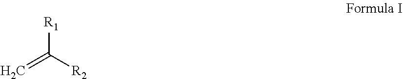
- the ( ⁇ CH 2 ) group in Formula I represents a polymerizable group, and is typically a UV-curable group, such that the material is a UV-curable material.
- R 1 is a poly(alkylene glycol), as defined herein.
- Non-limiting examples include polyethylene glycol diacrylate, polyethylene glycol dimethacrylate, polyethylene glycol-polyethylene glycol urethane diacrylate, and a partially acrylated polyol oligomer.
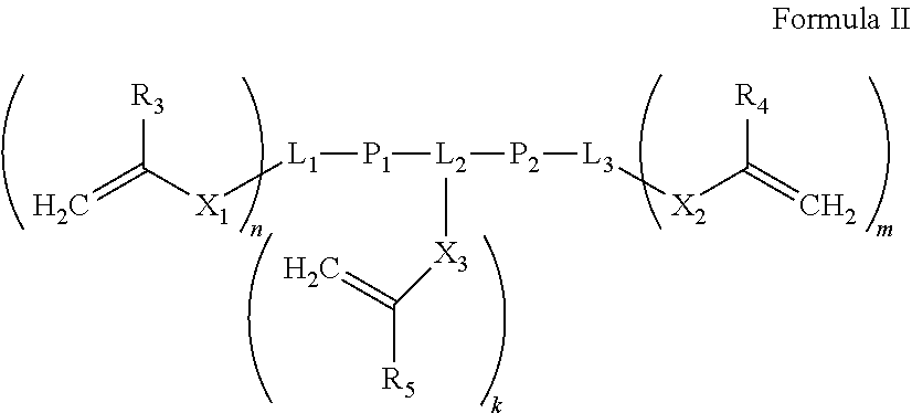
- one or more of P 1 and P 2 is, or comprises, a poly(alkylene glycol) moiety, as defined herein.
- R 3 , R 4 and R 5 is a hydrophilic group as described, for example, for R 1 and R 2 in Formula I, herein.
- P 1 and/or P 2 can be present or absent, and can be, or comprise, a hydrophilic group or not, as long as the material is hydrophilic, as defined herein.
- one, two or all of X 1 , X 2 and X 3 when present, can be —O—, such that at least one functional moiety in the multi-functional curable material is vinyl ether.
- a hydrophilic curable material as described herein is water-soluble or water-miscible.
- a “hydrophobic” curable material refers to materials which are characterized by Log P, when measured for water and octanol, higher than 1, and preferably higher.
- Exemplary multi-functional curable materials that are usable in the context of these embodiments include diacrylates such as aliphatic urethane diacrylate oligomer and/or monomeric diacrylates, preferably short chain diacrylates such as, but not limited to, isobornyl diacrylate.
- diacrylates such as aliphatic urethane diacrylate oligomer and/or monomeric diacrylates, preferably short chain diacrylates such as, but not limited to, isobornyl diacrylate.
- Hydrophobic curable materials are also referred to herein as apolar curable materials.
- Hydrophobic compounds dissolve more readily in oil or other hydrophobic solvents than in water. Hydrophobic compounds can be determined by, for example, as having Log P higher than 1, when Log P is determined in octanol and water phases, at a temperature lower than 50° C., or lower than 40° C., or lower than 35° C. or lower than 30° C., e.g., at 25° C.
- hydrophobic compounds can be determined by, for example, the Hansen parameters, as having relative energy distance (RED) lower than 1, when calculated for interaction with water as a solvent, at a temperature lower than 50, or lower than 40° C., or lower than 35° C. or lower than 30° C., e.g., at 25° C.
- a formulation which provides, when hardened, a non-elastomeric, rigid, material comprises:
- a total amount of the at least one hydrophobic curable material which provides, when hardened, a material featuring Tg higher than 80° C. is from 25 to 60 weight percents, or from 28 to 55 weight percents, of the total weight of the formulation comprising same, including any intermediate value and subranges therebetween.
- the hydrophobic curable material which provides, when hardened, a material featuring Tg higher than 80° C. comprises a mixture of a mono-functional curable material and a multi-functional curable material, and in some of these embodiments the multi-functional curable material is a di-functional curable material, as described herein in any of the respective embodiments and any combination thereof.
- a total amount of the at least one hydrophilic curable material which provides, when hardened, a material featuring Tg higher than 80° C. is from 15 to 35 weight percents of the total weight of the at least one formulation.
- an amount of the at least one hydrophilic multifunctional curable material which provides, when hardened, a material featuring Tg higher than 80° C. ranges from 0 to 5 weight percents of the total weight of the at least one formulation.
- a total amount of the at least one hydrophobic curable material which provides, when hardened, a material featuring Tg lower than 25° C. ranges from 0 to 15 of the total weight of the formulation comprising same, including any intermediate value and subranges therebetween.
- the at least one hydrophobic curable material which provides, when hardened, a material featuring Tg lower than 25° C. comprises at least one hydrophobic monofunctional curable material, and/or at least one hydrophobic multifunctional (e.g., difunctional) curable material, each independently provides the indicated Tg when hardened.
- an amount of the at least one hydrophobic monofunctional curable material which provides, when hardened, a material featuring Tg lower than 25° C. ranges from 0 to 5 weight percents of the total weight of the formulation comprising same, including any intermediate value and subranges therebetween.
- a total amount of the at least one hydrophilic curable material which provides, when hardened, a material featuring Tg lower than 25° C. ranges from 0 to 30 of the total weight of the formulation comprising same, including any intermediate value and subranges therebetween.
- the at least one hydrophilic curable material which provides, when hardened, a material featuring Tg lower than 25° C. comprises at least one hydrophilic monofunctional curable material and/or at least one hydrophilic multifunctional (e.g., di-functional) curable material, each independently provides, when hardened, the indicated Tg.
- an amount of the at least one multifunctional curable material ranges from 0 to 30 weight percents of the total weight of the formulation comprising same, including any intermediate value and subranges therebetween.
- a total amount of the at least one hydrophilic curable material which provides, when hardened, a material featuring Tg that ranges from 25° C. to 80° C. ranges from 0 to 15 of the total weight of the formulation comprising same, including any intermediate value and subranges therebetween.
- a total amount of hydrophobic curable materials in a formulation that provides a non-elastomeric, rigid, material as described herein ranges from 35-75 weight percents of the total weight of the formulation comprising same, including any intermediate value and subranges therebetween. In some of any of the embodiments described herein, a total amount of hydrophilic curable materials in a formulation that provides a non-elastomeric, rigid, material, ranges from 20-60 weight percents of the total weight of the formulation comprising same, including any intermediate value and subranges therebetween.
- a formulation that provides a non-elastomeric, rigid, material further comprises a curable material that features a viscosity at room temperature of no more than 15 centipoises, or even lower.
- curable material that features a viscosity at room temperature of no more than 15 centipoises, or even lower.
- Such materials are also referred to herein as “reactive diluents”.
- exemplary such materials include low molecular weight monofunctional and multifunctional divinyl ethers (e.g., DVE2, DVE3), and low molecular weight monofunctional and multifunctional (meth)acrylates (e.g., featuring short alkyls or short alkylene chains).
- an amount the curable material ranges from 0 to 7 weight percents of the total weight of the formulation comprising same.
- a formulation system that comprises one or more of a formulation as described in the foregoing embodiments can be used in additive manufacturing such as 3D inkjet printing in a single jetting mode, when the formulation system comprises one modeling material formulation, or in a multi material mode (PolyJet), including DM mode, when the formulation system comprises two or more modeling material formulations.
- additive manufacturing such as 3D inkjet printing in a single jetting mode, when the formulation system comprises one modeling material formulation, or in a multi material mode (PolyJet), including DM mode, when the formulation system comprises two or more modeling material formulations.
- the formulations can differ from another, for example, by different reactive (curable components) and/or by different non-reactive (non-curable) components, as described hereinafter, as long as it features the indicated viscosity and comprises curable materials as described in any of the respective embodiments.
- formulations usable in a formulation system that provides non-shelled three-dimensional objects, made of a single modeling material or of multi-materials, including digital materials.
- the at least one hydrophobic curable material which provides, when hardened, a material featuring Tg higher than 80° C. comprises at least one monofunctional curable material and/or at least one multifunctional curable material, as described herein in the respective embodiments.
- a total amount of the at least one hydrophilic curable material which provides, when hardened, a material featuring Tg higher than 80° C. is from 15 to 30 weight percents of the total weight of the formulation comprising same, including any intermediate values and subranges therebetween.
- the at least one hydrophilic curable material which provides, when hardened, a material featuring Tg higher than 80° C. comprises at least one monofunctional curable material and/or at least one multifunctional curable material.
- an amount of the at least one multifunctional curable material ranges from 0 to 5, e.g., 3 , weight percents of the total weight of the formulation comprising same, including any intermediate values and subranges therebetween.
- the multifunctional material is a trifunctional material, for example, an isocyanurate triacrylate.
- a total amount of the at least one hydrophilic curable material which provides, when hardened, a material featuring Tg lower than 25° C., if present, ranges from 0 to 10, or from 1 to 10, or from 2 to 8, e.g., about 5, weight percents, of the total weight of the formulation comprising same, including any intermediate values and subranges therebetween.
- At least one formulation in the formulation system of the present embodiments provides, when hardened, an elastomeric material, as defined herein.
- elastomeric curable material describes a curable material, as defined herein, which, upon exposure to a curing condition (e.g., curing energy), provides a cured material featuring properties of an elastomer (a rubber, or rubber-like material).
- a curing condition e.g., curing energy
- the carboxylate group, —C( ⁇ O)—OR′ comprises R′ which is an elastomeric moiety as described herein.
- R 1 is amide, and the compound is a mono-functional acrylamide monomer.
- R 2 is methyl, and the compound is mono-functional methacrylamide monomer.
- R 1 is a cyclic amide, and in some embodiments, it is a cyclic amide such as lactam, and the compound is a vinyl lactam. In some embodiments, R 1 is a cyclic carboxylate such as lactone, and the compound is a vinyl lactone.
- the mono-functional curable compound of Formula I is an exemplary polymeric or oligomeric mono-functional curable material. Otherwise, it is an exemplary monomeric mono-functional curable material.
- a multifunctional elastomeric material can be represented by Formula I as described herein, in which R 1 comprises an elastomeric material that terminates by a polymerizable group, as described herein.
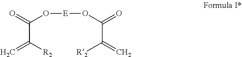
- a di-functional elastomeric curable material can be represented by Formula I*:
- a tri-functional elastomeric curable material can be represented by Formula III:
- a multi-functional (e.g., di-functional, tri-functional or higher) elastomeric curable material can be collectively represented by Formula IV:
- linking unit as used herein describes a multi-radical, preferably aliphatic or alicyclic group.
- multi-radical it is meant that the linking moiety has two or more attachment points such that it links between two or more atoms and/or groups or moieties.
- the branching unit is a chemical moiety that, when attached to a single position, group or atom of a substance, creates two or more functional groups that are linked to this single position, group or atom, and thus “branches” a single functionality into two or more functionalities.
- the elastomeric moiety e.g., Ra in Formula I or the moiety denoted as E in Formulae I*, III and IV, is or comprises an alkyl, which can be linear or branched, and which is preferably of 3 or more or of 4 or more carbon atoms; an alkylene chain, preferably of 3 or more or of 4 or more carbon atoms in length; an alkylene glycol as defined herein, an oligo(alkylene glycol), or a poly(alkylene glycol), as defined herein, preferably of 4 or more atoms in length, a urethane, an oligourethane, or a polyurethane, as defined herein, preferably of 4 or more carbon atoms in length, and any combination of the foregoing.
- an alkyl which can be linear or branched, and which is preferably of 3 or more or of 4 or more carbon atoms
- an alkylene chain preferably of 3 or more or of 4 or more carbon atoms in length
- the elastomeric curable material is a (meth)acrylic curable material, as described herein, and in some embodiments, it is an acrylate.
- the elastomeric curable material is or comprises a mono-functional elastomeric curable material, and is some embodiments, the mono-functional elastomeric curable material is represented by Formula I, wherein R 1 is —C( ⁇ O)—OR′ and R′ is an alkylene chain (e.g., of 4 or more, preferably 6 or more, preferably 8 or more, carbon atoms in length), or a poly(alkylene glycol) chain, as defined herein.
- R 1 is —C( ⁇ O)—OR′ and R′ is an alkylene chain (e.g., of 4 or more, preferably 6 or more, preferably 8 or more, carbon atoms in length), or a poly(alkylene glycol) chain, as defined herein.
- the elastomeric curable material is or comprises a multi-functional elastomeric curable material, and is some embodiments, the multi-functional elastomeric curable material is represented by Formula I*, wherein E is an alkylene chain (e.g., of 4 or more, or 6 or more, carbon atoms in length), and/or a poly(alkylene glycol) chain, as defined herein.
- E is an alkylene chain (e.g., of 4 or more, or 6 or more, carbon atoms in length), and/or a poly(alkylene glycol) chain, as defined herein.
- the elastomeric curable material is or comprises a multi-functional elastomeric curable material, and is some embodiments, the multi-functional elastomeric curable material is represented by Formula III, wherein E is a branched alkyl (e.g., of 3 or more, or of 4 or more, or of 5 or more, carbon atoms in length).
- Exemplary elastomeric acrylate and methacrylate curable materials include, but are not limited to, 2-propenoic acid, 2-[[(butylamino)carbonyl]oxy]ethyl ester (an exemplary urethane acrylate), and compounds marketed under the trade names SR335 (Lauryl acrylate) and SR395 (isodecyl acrylate) (by Sartomer).
- SR350D a trifunctional trimethylolpropane trimethacrylate (TMPTMA), SR256 (2-(2-ethoxyethoxy)ethyl acrylate, SR252 (polyethylene glycol (600) dimethacrylate), SR561 (an alkoxylated hexane diol diacrylate) (by Sartomer).
- SR350D a trifunctional trimethylolpropane trimethacrylate
- SR256 (2-(2-ethoxyethoxy)ethyl acrylate
- SR252 polyethylene glycol (600) dimethacrylate
- SR561 an alkoxylated hexane diol diacrylate
- Additional examples include curable materials marketed as the Genomer family (e.g., Genomer 1122).
- acrylic materials featuring, for example, one or more acrylamide groups instead of one or more acrylate or methacrylate groups are also contemplated.
- the elastomeric curable material comprises one or more mono-functional elastomeric curable material(s) (e.g., a mono-functional elastomeric acrylate, as represented, for example, in Formula I) and one or more multi-functional (e.g., di-functional) elastomeric curable materials(s) (e.g., a di-functional elastomeric acrylate, as represented, for example, in Formula I*, III or IV) and in any of the respective embodiments as described herein.
- mono-functional elastomeric curable material(s) e.g., a mono-functional elastomeric acrylate, as represented, for example, in Formula I
- multi-functional elastomeric curable materials(s) e.g., a di-functional elastomeric acrylate, as represented, for example, in Formula I*, III or IV
- the additional curable material is a mono-functional acrylate or methacrylate ((meth)acrylate).
- Non-limiting examples include isobornyl acrylate (IBOA), isobornylmethacrylate, acryloyl morpholine (ACMO), tetrahydrofutyl acrylate, phenoxyethyl acrylate, marketed by Sartomer Company (USA) under the trade name SR-339, urethane acrylate oligomer such as marketed under the name CN 131B, and any other acrylates and methacrylates usable in AM methodologies.
- IBOA isobornyl acrylate
- ACMO acryloyl morpholine
- tetrahydrofutyl acrylate tetrahydrofutyl acrylate
- phenoxyethyl acrylate marketed by Sartomer Company (USA) under the trade name SR-339
- urethane acrylate oligomer such as
- a total amount of the elastomeric curable material(s) is at least 30, preferably at least 35, weight percents, of the total weight of a formulation comprising same. In some of any of the embodiments described herein for elastomeric materials, a total amount of the elastomeric curable material(s) ranges from about 30 to about 70, or from about 35 to about 65, weight percents of the total weight of the formulation comprising same, including any intermediate values and subranges therebetween.
- an amount of hydrophobic monofunctional curable material(s) that provide, when hardened, a material featuring Tg of at least 80° C. ranges from about 20 to about 30, or from about 25 to about 30, weight percents of the total weight of the formulation comprising same, including any intermediate and subranges therebetween.
- the monofunctional curable material(s) comprise one or more hydrophobic monofunctional curable material(s) that provide, when hardened, a material featuring Tg lower than 25° C. Exemplary such materials are as described herein.
- an amount of hydrophobic monofunctional curable material(s) that provide, when hardened, a material featuring Tg lower than 25° C. is no more than 25 weight percents weight percents of the total weight of the formulation comprising same, and in some embodiments it is from about 10 to about 25 or from about 20 to about 25, weight percents, including any intermediate and subranges therebetween. Exemplary materials are presented in Table 2, below.
- a difunctional curable material if present in the formulation, is in an amount of from about 1 to about 15 weight percents of the total weight of the formulation comprising same, including any intermediate values and subranges therebetween, and in some embodiments it is either absent or is in an amount of from 1 to 10, from 3 to 6, e.g., from about 4 to about 5, weight percents of the total weight of a formulation comprising same.
- the formulation system consists of one formulation, unless otherwise indicated.
- the formulation system further comprises a photoinitiator.
- suitable photoinitiators include benzophenones (aromatic ketones) such as benzophenone, methyl benzophenone, Michler's ketone and xanthones; acylphosphine oxide type photo-initiators such as 2,4,6-trimethylbenzolydiphenyl phosphine oxide (TMPO), 2,4,6-trimethylbenzoylethoxyphenyl phosphine oxide (TEPO), and bisacylphosphine oxides (BAPO's); benzoins and benzoin alkyl ethers such as benzoin, benzoin methyl ether and benzoin isopropyl ether and the like.
- TMPO 2,4,6-trimethylbenzolydiphenyl phosphine oxide
- TEPO 2,4,6-trimethylbenzoylethoxyphenyl phosphine oxide
- BAPO's bisacylphosphine oxides
- Such agents include, for example, surface active agents, stabilizers, antioxidants, fillers, pigments, dispersants, and/or impact modifying agents (toughening agents or toughness modifiers).
- filler describes an inert material that modifies the properties of a polymeric material and/or adjusts a quality of the end products.
- the filler may be an inorganic particle, for example calcium carbonate, silica, and clay.
- a modeling formulation comprises a surface active agent and/or a dispersant.
- a surface-active agent may be used to reduce the surface tension of the formulation to the value required for jetting or for printing process, which is typically between 10 dyne/cm and 50 dyne/cm, for instance about 30 dyne/cm.
- An exemplary such agent is a silicone surface additive, e.g., of the BYK family.
- a concentration of a dispersant ranges from 0 to about 2% weight, and is, for example, 0, 0.1, 0.5, 0.7, 1, 1.2, 1.3, 1.35, 1.4, 1.5, 1.7, 1.8 or about 2%, by weight, including any intermediate value therebetween, of the total weight of the formulation or formulation system comprising same.
- the modeling formulation comprises one or more pigments.
- the pigment's concentration is lower than 35%, or lower than 25% or lower than 15%, by weight.
- an amount of a pigment in a formulation comprising same ranges from 0.1 to 5, or 1 to 5, or 1 to 3, or 1 to 2, % by weight of the total weight of a formulation comprising same.
- the pigment may be a white pigment.
- the pigment may be an organic pigment or an inorganic pigment, or a metal pigment or a combination thereof.
- the dye may be any of a broad class of solvent soluble dyes.
- Some non-limiting examples are azo dyes which are yellow, orange, brown and red; anthraquinone and triarylmethane dyes which are green and blue; and azine dye which is black.
- Non-limiting examples of toughening agents include elastomeric materials.
- Representative examples include, without limitation, natural rubber, butyl rubber, polyisoprene, polybutadiene, polyisobutylene, ethylene-propylene copolymer, styrene-butadiene-styrene triblock rubber, random styrene-butadiene rubber, styrene-isoprene-styrene triblock rubber, styrene-ethylene/butylene-styrene copolymer, styrene-ethylene/propylene-styrene copolymer, ethylene-propylene-diene terpolymers, ethylene-vinyl acetate and nitrile rubbers.
- Preferred agents are elastomers such as polybutadienes.
- Toughening agents such as elastomeric materials can be added to the formulation by incorporating in a modeling material formulation an elasto
- a concentration of elastomeric materials may range from about 0.10 phr to about 10 phr, or from about 0.1 phr to about 5 phr, relative to the weight of the formulation containing same.
- a concentration of elastomeric materials may alternatively range from about 0.1% to about 20%, by weight, of the total weight of a formulation containing same.
- impact modifying agents such as, for example, carbon fibers, carbon nanotubes, glass fibers, aramid Kevlar, polyparaphenylene benzobisoxazole Zylon, and other polar and non-polar impact modifiers, are also contemplated.
- one or more of the modeling material formulation(s) further comprises a polymerization inhibitor.
- a concentration of an inhibitor ranges from 0 to about 2% weight, or from 0 to about 1%, and is, for example, 0, 0.1, 0.2, 0.3, 0.4, 0.5, 0.6, 0.7, 0.8, 0.9 or about 1%, by weight, including any intermediate value therebetween, of the total weight of the formulation or a formulation system comprising same.
- manufacturing of shelled objects is performed using two formulations: a first formulation, Part A, referred to also as RF (reinforcer); and a second formulation, Part B, referred to also as DLM.
- RF reinforcement
- DLM second formulation
- the first formulation (Part A, RF) provides, when hardened, a rigid material characterized by high HDT (e.g., higher than 70° C., or higher than 90° C.)
- the second formulation (Part B, DLM) provides, when hardened, a material which is less rigid than the material obtained from a hardened first formulation (RF), and which is characterized by high toughness (e.g., Izod notch Impact higher than 30 J/mol, or higher of 35 J/mol, for example, of about 30-100 J/m), and HDT lower than the first hardened formulation RF (e.g., HDT of about 40-41° C.).
- high HDT e.g., higher than 70° C., or higher than 90° C.
- the second formulation (Part B, DLM) provides, when hardened, a material which is less rigid than the material obtained from a hardened first formulation (RF), and which is characterized by high toughness (e.g., Izod notch Impact higher than 30 J/
- Table 2 below presents exemplary chemical compositions of modeling material formulations suitable for use in 3D inkjet printing of elastomeric materials, as defined herein, in, for example, single jetting and PolyJet technologies, including DM mode.
- exemplary formulations for forming elastomeric materials elastomeric curable materials at a concentration of at least 30% by weight, combined with one or more non-elastomeric monofunctional curable materials, at a total weight of no more than 60% by weight, and optionally one or more non-elastomeric difunctional curable materials, at a total weight of no more than 10%, preferably no more than 6%, by weight, of the total weight of the formulation, and further optionally one or more non-reactive materials (non-reactive diluents) that feature low viscosity at room temperature (e.g., lower than 20 cPs).
- non-reactive materials non-reactive diluents
- Non-elastomeric IBOA 20-60 Monofunctional (Isobornyl acrylate; curable (meth)acrylic CAS:5888-33-5) material
- IBOMA Isobornyl methacrylate; CAS: 7534-94-3; SR 423D) CN131B (2-Hydroxy-3-phenoxypropyl prop-2-enoate)
- SR285 Tetrahydrofuryl Acrylate
- Non-elastomeric SR 9036 0-6 Difunctional curable (Ethoxylated (30) bisphenol A (meth)acrylic material dimethacrylate; CAS: 41637-38-1)
- Ebecryl 230 Aliphatic Urethane Diacrylate
- Elastomeric Genomer 1122 35-60 (meth)acrylic material (2-[[(Butylamino)carbonyl]- oxy]ethyl acrylate)
Landscapes
- Chemical & Material Sciences (AREA)
- Engineering & Computer Science (AREA)
- Materials Engineering (AREA)
- Manufacturing & Machinery (AREA)
- Physics & Mathematics (AREA)
- Mechanical Engineering (AREA)
- Optics & Photonics (AREA)
Abstract
Description
(MW×% wt. of A+MW a% wt. of B)/total % wt. of curable materials.
Elongation is typically determined according to ASTM D412.
-
- wherein at least one of R1 and R2 is and/or comprises a hydrophilic group, as defined herein.
-
- wherein:
- each of R3, R4 and R5 is independently hydrogen, C(1-4)alkyl, or a hydrophilic group, as defined herein;
- each of L1, L2 and L3 is independently a linking moiety or absent;
- each of P1 and P2 is independently a hydrophilic group as defined herein or absent;
- each of X1, X2 and X3 is independently C(1-4)alkyl, or a hydrophilic group, as defined herein, or absent; and
- each of n, m and k is 0, 1, 2, 3 or 4,
- provided that n+m+k is at least 2, and provided that at least one of R3, R4, R5, X1, X2, X3 P1 and P2 is a hydrophilic group, as defined herein.
-
- wherein E is an elastomeric linking moiety as described herein, and R′2 is as defined herein for R2.

-
- wherein E is an elastomeric linking moiety as described herein, and R′2 and R″2 are each independently as defined herein for R2.
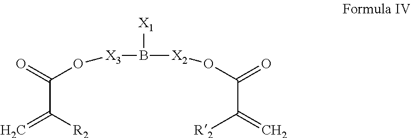
-
- Wherein:
- R2 and R′2 are as defined herein;
- B is a di-functional or tri-functional branching unit as defined herein (depending on the nature of X1);
- X2 and X3 are each independently absent, an elastomeric moiety as described herein, or is selected from an alkyl, a hydrocarbon, an alkylene chain, a cycloalkyl, an aryl, an alkylene glycol, a urethane moiety, and any combination thereof; and
- X1 is absent or is selected from an alkyl, a hydrocarbon, an alkylene chain, a cycloalkyl, an aryl, an alkylene glycol, a urethane moiety, and an elastomeric moiety, each being optionally being substituted (e.g., terminated) by a meth(acrylate) moiety (O—C(═O) CR″2═CH2), and any combination thereof, or, alternatively, X1 is:
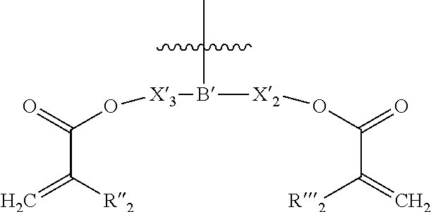
-
- wherein:
- the curved line represents the attachment point;
- B′ is a branching unit, being the same as, or different from, B;
- X′2 and X′3 are each independently as defined herein for X2 and X3; and
- R″2 and R′″2 are as defined herein for R2 and R′2.
- provided that at least one of X1, X2 and X3 is or comprises an elastomeric moiety as described herein.
-
- one or more elastomeric curable material(s), as defined herein in any of the respective embodiments; and one or more mono-functional curable material(s).
| TABLE 1 | ||
| Component | Exemplary Materials | Percentage (%) |
| Hydrophobic curable | IBOA (monofunctional) | Total: 25-60 |
| (meth)acrylic material, | (Isobornyl acrylate; CAS:5888-33-5) | Monofunctional: 30-55 |
| characterized, when | (Tg = 95° C.) | Multifunctional: 0-25 |
| hardened, | IBOMA (monofunctional) | For Single and PolyJet |
| by Tg > 50° C. | (Isobornyl methacrylate; CAS: 7534- | Total: 50-60 |
| 94-3; SR 423D) | Monofunctional: 30-60 | |
| (Tg = 175° C.) | Multifunctional: 0-25 | |
| SR 833S (difunctional) | For RF | |
| (Tricyclodecanedimethanol | Total: 50-60 | |
| Diacrylate; CAS: 42594-17-2) | Monofunctional: 25-40 | |
| (Tg = 185° C.) | Multifunctional: 15-30 | |
| For DLM | ||
| Total: 30-45 | ||
| Monofunctional: 25-40 | ||
| Multifunctional: 0-25 | ||
| Hydrophilic curable | ACMO (Monofunctional) | Total: 15-35 |
| (meth)acrylic material, | (Acryloyl Morpholine; | Monofunctional: 15-30 |
| characterized, when | CAS: 5117-12-4) | Multifunctional: 0-5 |
| hardened, by Tg > 50° C. | (Tg = 145° C.) | For Single and PolyJet |
| SR368 (Trifunctional) | Total: 15-30 | |
| (Tris(2-Hydroxy Ethyl)Isocyanurate | Monofunctional: 15-25 | |
| Triacrylate; CAS: 40220-08-4) | Multifunctional: 0-5 | |
| (Tg = 272° C.) | For RF | |
| Total: 25-35 | ||
| Monofunctional: 20-35 | ||
| Multifunctional: 0-5 | ||
| For DLM | ||
| Total: 25-35 | ||
| Monofunctional: 20-35 | ||
| Multifunctional: 0-5 | ||
| Hydrophobic | SR 531 (Monofunctional) | Total: 0-15 |
| (meth)acrylic flexible | (Cyclic Trimethylopropane Formal | Monofunctional: 0-5 |
| material, | Acrylate) | Multifunctional: 0-10 |
| characterized, when | CN131B (Monofunctional) | For Single and PolyJet |
| hardened, by Tg < 25° C. | (2-Hydroxy-3-phenoxypropyl | Total: 0-15 |
| prop-2-enoate) | Monofunctional: 0-5 | |
| CN991 (Difunctional) | Multifunctional: 5-15 | |
| (Aliphatic urethane diacrylate) | For RF | |
| Total: 0-15 | ||
| Monofunctional: 0-5 | ||
| Multifunctional: 0-15 | ||
| For DLM | ||
| Total: 0-5 | ||
| Monofunctional: 0-5 | ||
| Multifunctional: 0-5 | ||
| Hydrophilic | SR 9036 (difunctional) | Total: 0-30 |
| (meth)acrylic flexible | (Ethoxylated (30) bisphenol A | Difunctional: 0-5 |
| material, | dimethacrylate; CAS: 41637-38-1) | Trifunctional: 0-30 |
| characterized, when | (Tg = −43° C.) | For Single and PolyJet |
| hardened, by Tg < 25° C. | SR415 (trifunctional) | Total: 1-10 |
| (Ethoxylated (20) Trimethylol | difunctional: 1-10 | |
| propane triacrylate; CAS: | trifunctional: 0-5 | |
| 28961-43-5) | For RF | |
| (Tg = −40° C.) | Total: 0-5 | |
| SR 9035 (Ethoxylated (15) | difunctional: 0-5 | |
| Trimethylol propane triacrylate | trifunctional: 0-5 | |
| (Tg = −30° C.) | For DLM | |
| Total: 10-30 | ||
| difunctional: 0-5 | ||
| trifunctional: 10-30 | ||
| Hydrophilic curable | AgiSyn 1030 (difunctional) | Total: 0-15 |
| (meth)acrylic material, | (Exo-1,7,7-trimethylbicyclo | |
| characterized, when | [2.2.1]hept-2-yl acrylate) | |
| hardened, by 80° C. > | (Tg = 60° C.) | |
| Tg > 25° C. | Photomer ® 6019 (Trifunctional) | |
| (Aliphatic urethane triacrylate) | ||
| (Tg = 51° C.) | ||
| Total hydrophilic | 20-60 | |
| curable materials | ||
| Total hydrophobic | 35-75 | |
| curable materials | ||
| Reactive diluent | DVE3 (Difunctional) | 0-10 |
| (Triethyleneglycol divinyl ether) | (eg., 0-7) | |
| DVE2 (Difunctional) | ||
| (Diethyleneglycol divinyl ether) | ||
| Photoinitiator | BAPO type | 1-3 |
| (Bis Acyl Phosphine Oxide) | (e.g., 1-2) | |
| Alpha Hydroxy ketone | ||
| MAPO (Monoacylphosphine oxides) | ||
| Surfactant/Dispersant | BYK Type (PDMS derivatives) | 0-1 |
| Inhibitor | MEHQ | 0.01-1 |
| Genorad Type | ||
| Inorganic/Organic | Nano scale Titanium Oxide | 0-2 |
| Pigment | Nano scale Zirconium Oxide | |
| Nano Silica | ||
| Nano scale Carbon black | ||
Modeling Material Formulation Providing, when Hardened, Elastomeric Materials
| TABLE 2 | ||
| Percentage | ||
| Component | Exemplary Materials | (%) |
| Non-elastomeric | IBOA | 20-60 |
| Monofunctional | (Isobornyl acrylate; | |
| curable (meth)acrylic | CAS:5888-33-5) | |
| material | IBOMA | |
| (Isobornyl methacrylate; CAS: | ||
| 7534-94-3; SR 423D) | ||
| CN131B | ||
| (2-Hydroxy-3-phenoxypropyl | ||
| prop-2-enoate) | ||
| SR285 | ||
| (Tetrahydrofuryl Acrylate) | ||
| Non-elastomeric | SR 9036 | 0-6 |
| Difunctional curable | (Ethoxylated (30) bisphenol A | |
| (meth)acrylic material | dimethacrylate; | |
| CAS: 41637-38-1) | ||
| Ebecryl 230 | ||
| (Aliphatic Urethane Diacrylate) | ||
| Elastomeric | Genomer 1122 | 35-60 |
| (meth)acrylic material | (2-[[(Butylamino)carbonyl]- | |
| oxy]ethyl acrylate) | ||
| Non-Reactive diluent | PPG600 | 0-15 |
| Photoinitiator | BAPO type (Bis Acyl Phosphine | 1-3 |
| Oxide) | (e.g., 1-2) | |
| Alpha Hydroxy ketone | ||
| MAPO (Monoacylphosphine oxides) | ||
| Surfactant/Dispersant | BYK Type (PDMS derivatives) | 0-1 |
| Inhibitor | MEHQ | 0.01-1 |
| Genorad Type | ||
| Inorganic/Organic | Nano scale Titanium Oxide | 0-2 |
| Pigment | Nano scale Zirconium Oxide | |
| Nano Silica | ||
| Nano scale carbon black | ||
Claims (20)
Priority Applications (1)
| Application Number | Priority Date | Filing Date | Title |
|---|---|---|---|
| US17/419,817 US12269214B2 (en) | 2018-12-31 | 2019-12-30 | Method and system for three-dimensional printing |
Applications Claiming Priority (3)
| Application Number | Priority Date | Filing Date | Title |
|---|---|---|---|
| US201862786577P | 2018-12-31 | 2018-12-31 | |
| PCT/IL2019/051438 WO2020141518A1 (en) | 2018-12-31 | 2019-12-30 | Method and system for three-dimensional printing |
| US17/419,817 US12269214B2 (en) | 2018-12-31 | 2019-12-30 | Method and system for three-dimensional printing |
Publications (2)
| Publication Number | Publication Date |
|---|---|
| US20220080665A1 US20220080665A1 (en) | 2022-03-17 |
| US12269214B2 true US12269214B2 (en) | 2025-04-08 |
Family
ID=69165452
Family Applications (1)
| Application Number | Title | Priority Date | Filing Date |
|---|---|---|---|
| US17/419,817 Active 2041-05-23 US12269214B2 (en) | 2018-12-31 | 2019-12-30 | Method and system for three-dimensional printing |
Country Status (6)
| Country | Link |
|---|---|
| US (1) | US12269214B2 (en) |
| EP (2) | EP3906146B1 (en) |
| JP (1) | JP7467474B2 (en) |
| CN (1) | CN113316510B (en) |
| IL (1) | IL284507B2 (en) |
| WO (1) | WO2020141518A1 (en) |
Families Citing this family (3)
| Publication number | Priority date | Publication date | Assignee | Title |
|---|---|---|---|---|
| IL275769B2 (en) * | 2017-12-31 | 2024-07-01 | Stratasys Ltd | Modeling material formulations usable in additive manufacturing of three-dimensional objects at low temperatures |
| US12269214B2 (en) | 2018-12-31 | 2025-04-08 | Stratasys Ltd. | Method and system for three-dimensional printing |
| EP4688887A1 (en) * | 2023-03-31 | 2026-02-11 | Stratasys Ltd. | Formulations usable in additive manufacturing of 3d objects that feature an elastomeric material |
Citations (22)
| Publication number | Priority date | Publication date | Assignee | Title |
|---|---|---|---|---|
| US6259962B1 (en) | 1999-03-01 | 2001-07-10 | Objet Geometries Ltd. | Apparatus and method for three dimensional model printing |
| US6569373B2 (en) | 2000-03-13 | 2003-05-27 | Object Geometries Ltd. | Compositions and methods for use in three dimensional model printing |
| US6658314B1 (en) | 1999-10-06 | 2003-12-02 | Objet Geometries Ltd. | System and method for three dimensional model printing |
| US6850334B1 (en) | 2000-01-18 | 2005-02-01 | Objet Geometries Ltd | System and method for three dimensional model printing |
| US20060127153A1 (en) | 2002-11-12 | 2006-06-15 | Guy Menchik | Three-dimensional object printing |
| US7183335B2 (en) | 2000-03-13 | 2007-02-27 | Objet Geometries Ltd. | Compositions and methods for use in three dimensional model printing |
| US7209797B2 (en) | 2002-01-03 | 2007-04-24 | Objet Geometries Ltd. | System and method for accurate printing of three dimensional models utilizing adjustment parameters |
| US7300619B2 (en) | 2000-03-13 | 2007-11-27 | Objet Geometries Ltd. | Compositions and methods for use in three dimensional model printing |
| US7500846B2 (en) | 2003-05-01 | 2009-03-10 | Objet Geometries Ltd. | Rapid prototyping apparatus |
| EP2199066A1 (en) | 2008-12-19 | 2010-06-23 | Agfa Graphics N.V. | Method for reducing image quality artifacts in three-dimensional printing |
| US20100191360A1 (en) | 2007-07-25 | 2010-07-29 | Object Geometries Ltd. | Solid freeform fabrication using a plurality of modeling materials |
| US7962237B2 (en) | 2008-08-06 | 2011-06-14 | Objet Geometries Ltd. | Method and apparatus for optimizing a scanning plan in three-dimensional printing |
| CN106515013A (en) | 2015-09-14 | 2017-03-22 | 施乐公司 | Thermal management methods and apparatus for producing uniform material deposition and curing for high speed three-dimensional printing |
| EP3253560A1 (en) * | 2015-02-05 | 2017-12-13 | Stratasys Ltd. | Digitally-controlled three-dimensional printing of polymerizable materials |
| JP2018002768A (en) | 2016-06-28 | 2018-01-11 | 株式会社リコー | Active energy ray-curable liquid composition, manufacturing method of three-dimensional molded article and manufacturing apparatus of three-dimensional molded article |
| WO2018015553A1 (en) | 2016-07-22 | 2018-01-25 | Dsm Ip Assets B.V. | Methods and compositions for forming three-dimensional objects by additive fabrication |
| US20180071984A1 (en) | 2015-03-16 | 2018-03-15 | Lg Electronics Inc. | Printing apparatus for building three-dimensional object |
| WO2018055522A1 (en) | 2016-09-22 | 2018-03-29 | Stratasys Ltd. | Formulation, method and system for solid freeform fabrication |
| US20180111336A1 (en) * | 2016-10-26 | 2018-04-26 | Xerox Corporation | Method of operating extruder heads in three-dimensional object printers |
| JP2018115243A (en) | 2017-01-17 | 2018-07-26 | 株式会社リコー | Active energy ray curable composition, active energy ray curable ink, composition container, two-dimensional or three-dimensional image forming method and forming apparatus, two-dimensional or three-dimensional image, structure, and molded product |
| JP2018199336A (en) | 2018-08-22 | 2018-12-20 | 株式会社ミマキエンジニアリング | Forming apparatus and forming method for three-dimensional structure |
| WO2020141518A1 (en) | 2018-12-31 | 2020-07-09 | Stratasys Ltd. | Method and system for three-dimensional printing |
Family Cites Families (2)
| Publication number | Priority date | Publication date | Assignee | Title |
|---|---|---|---|---|
| WO2011135496A2 (en) | 2010-04-25 | 2011-11-03 | Objet Geometries Ltd. | Solid freeform fabrication of shelled objects |
| FR3041779B1 (en) | 2015-09-30 | 2017-10-20 | Peugeot Citroen Automobiles Sa | METHOD FOR CONTROLLING A TRANSMISSION IN PARTICULAR OF A MOTOR VEHICLE |
-
2019
- 2019-12-30 US US17/419,817 patent/US12269214B2/en active Active
- 2019-12-30 IL IL284507A patent/IL284507B2/en unknown
- 2019-12-30 JP JP2021536306A patent/JP7467474B2/en active Active
- 2019-12-30 EP EP19836595.9A patent/EP3906146B1/en active Active
- 2019-12-30 EP EP24150272.3A patent/EP4324651A3/en active Pending
- 2019-12-30 WO PCT/IL2019/051438 patent/WO2020141518A1/en not_active Ceased
- 2019-12-30 CN CN201980090056.1A patent/CN113316510B/en active Active
Patent Citations (31)
| Publication number | Priority date | Publication date | Assignee | Title |
|---|---|---|---|---|
| US6259962B1 (en) | 1999-03-01 | 2001-07-10 | Objet Geometries Ltd. | Apparatus and method for three dimensional model printing |
| US6658314B1 (en) | 1999-10-06 | 2003-12-02 | Objet Geometries Ltd. | System and method for three dimensional model printing |
| US7225045B2 (en) | 1999-10-06 | 2007-05-29 | Object Geometries Ltd. | System and method for three dimensional model printing |
| US6850334B1 (en) | 2000-01-18 | 2005-02-01 | Objet Geometries Ltd | System and method for three dimensional model printing |
| US7300619B2 (en) | 2000-03-13 | 2007-11-27 | Objet Geometries Ltd. | Compositions and methods for use in three dimensional model printing |
| US6569373B2 (en) | 2000-03-13 | 2003-05-27 | Object Geometries Ltd. | Compositions and methods for use in three dimensional model printing |
| US7183335B2 (en) | 2000-03-13 | 2007-02-27 | Objet Geometries Ltd. | Compositions and methods for use in three dimensional model printing |
| US7479510B2 (en) | 2000-03-13 | 2009-01-20 | Objet Geometries Ltd. | Compositions and methods for use in three dimensional model printing |
| US7209797B2 (en) | 2002-01-03 | 2007-04-24 | Objet Geometries Ltd. | System and method for accurate printing of three dimensional models utilizing adjustment parameters |
| EP1938952A2 (en) | 2002-11-12 | 2008-07-02 | Objet Geometries Ltd. | Three-dimensional object printing |
| US20060127153A1 (en) | 2002-11-12 | 2006-06-15 | Guy Menchik | Three-dimensional object printing |
| US7500846B2 (en) | 2003-05-01 | 2009-03-10 | Objet Geometries Ltd. | Rapid prototyping apparatus |
| US20130073068A1 (en) | 2007-07-25 | 2013-03-21 | Objet Ltd. | Solid freeform fabrication using a plurality of modeling materials |
| US9031680B2 (en) | 2007-07-25 | 2015-05-12 | Stratasys Ltd. | Solid freeform fabrication using a plurality of modeling materials |
| US20100191360A1 (en) | 2007-07-25 | 2010-07-29 | Object Geometries Ltd. | Solid freeform fabrication using a plurality of modeling materials |
| US7962237B2 (en) | 2008-08-06 | 2011-06-14 | Objet Geometries Ltd. | Method and apparatus for optimizing a scanning plan in three-dimensional printing |
| EP2199066A1 (en) | 2008-12-19 | 2010-06-23 | Agfa Graphics N.V. | Method for reducing image quality artifacts in three-dimensional printing |
| US20180029291A1 (en) | 2015-02-05 | 2018-02-01 | Stratasys Ltd. | Digitally-controlled three-dimensional printing of polymerizable materials |
| EP3253560A1 (en) * | 2015-02-05 | 2017-12-13 | Stratasys Ltd. | Digitally-controlled three-dimensional printing of polymerizable materials |
| US20180071984A1 (en) | 2015-03-16 | 2018-03-15 | Lg Electronics Inc. | Printing apparatus for building three-dimensional object |
| CN106515013A (en) | 2015-09-14 | 2017-03-22 | 施乐公司 | Thermal management methods and apparatus for producing uniform material deposition and curing for high speed three-dimensional printing |
| JP2018002768A (en) | 2016-06-28 | 2018-01-11 | 株式会社リコー | Active energy ray-curable liquid composition, manufacturing method of three-dimensional molded article and manufacturing apparatus of three-dimensional molded article |
| WO2018015553A1 (en) | 2016-07-22 | 2018-01-25 | Dsm Ip Assets B.V. | Methods and compositions for forming three-dimensional objects by additive fabrication |
| JP2019521015A (en) | 2016-07-22 | 2019-07-25 | ディーエスエム アイピー アセッツ ビー.ブイ.Dsm Ip Assets B.V. | Methods and compositions for forming three-dimensional objects by additive manufacturing |
| JP2019521883A (en) | 2016-07-22 | 2019-08-08 | ディーエスエム アイピー アセッツ ビー.ブイ.Dsm Ip Assets B.V. | Method and composition for forming a three-dimensional object by additive manufacturing |
| WO2018055522A1 (en) | 2016-09-22 | 2018-03-29 | Stratasys Ltd. | Formulation, method and system for solid freeform fabrication |
| JP2019529183A (en) | 2016-09-22 | 2019-10-17 | ストラタシス リミテッド | Formulations, methods, and systems for solid freeform fabrication |
| US20180111336A1 (en) * | 2016-10-26 | 2018-04-26 | Xerox Corporation | Method of operating extruder heads in three-dimensional object printers |
| JP2018115243A (en) | 2017-01-17 | 2018-07-26 | 株式会社リコー | Active energy ray curable composition, active energy ray curable ink, composition container, two-dimensional or three-dimensional image forming method and forming apparatus, two-dimensional or three-dimensional image, structure, and molded product |
| JP2018199336A (en) | 2018-08-22 | 2018-12-20 | 株式会社ミマキエンジニアリング | Forming apparatus and forming method for three-dimensional structure |
| WO2020141518A1 (en) | 2018-12-31 | 2020-07-09 | Stratasys Ltd. | Method and system for three-dimensional printing |
Non-Patent Citations (13)
| Title |
|---|
| Communication Pursuant to Article 94(3) EPC Dated Jan. 5, 2024 From the European Patent Office Re. Application No. 19836595.9 (5 Pages). |
| Communication Pursuant to Article 94(3) EPC Dated Sep. 27, 2022 From the European Patent Office Re. Application No. 19836595.9. (6 pages). |
| English Summary Dated Mar. 30, 2023 of Notification of Office Action and Search Report Dated Mar. 24, 2023 From the State Intellectual Property Office of the People's Republic of China Re. Application No. 201980090056.1 (1 page). |
| International Preliminary Report on Patentability Dated Jul. 15, 2021 From the International Bureau of WIPO Re. Application No. PCT/IL2019/051438. (10 Pages). |
| International Search Report and the Written Opinion Dated Mar. 23, 2020 From the International Searching Authority Re. Application No. PCT/IL2019/051438. (15 Pages). |
| Matzner EP3253560A1 English Translation 2017, Equivalent to US-2018029291A1 (Year: 2017). * |
| Notice of Reason(s) for Rejection Dated Sep. 19, 2023 From the Japan Patent Office Re. Application No. 2021-536306. (3 pages). |
| Notification of Office Action and Search Report Dated Aug. 24, 2022 From the State Intellectual Property Office of the People's Republic of China Re. Application No. 201980090056.1 and Its Summary in English. (11 Pages). |
| Notification of Office Action and Search Report Dated Mar. 24, 2023 From the State Intellectual Property Office of the People's Republic of China Re. Application No. 201980090056.1 (3 Pages). |
| Office Action Dated Jun. 13, 2024 From the Israel Patent Office Re. Application No. 284507. (4 Pages). |
| Supplementary European Search Report and the European Search Opinion Dated Jun. 7, 2024 From the European Patent Office Re. Application No. 24150272.3. (10 Pages). |
| Translation Dated Mar. 30, 2023 of Notification of Office Action and Search Report Dated Mar. 24, 2023 From the State Intellectual Property Office of the People's Republic of China Re. Application No. 201980090056.1 (2 pages). |
| Translation Dated Oct. 6, 2023 of Notice of Reason(s) for Rejection Dated Sep. 19, 2023 From the Japan Patent Office Re. Application No. 2021-536306. (5 pages). |
Also Published As
| Publication number | Publication date |
|---|---|
| IL284507B2 (en) | 2025-12-01 |
| WO2020141518A1 (en) | 2020-07-09 |
| EP3906146B1 (en) | 2025-01-29 |
| JP7467474B2 (en) | 2024-04-15 |
| EP4324651A3 (en) | 2024-07-10 |
| EP3906146A1 (en) | 2021-11-10 |
| CN113316510A (en) | 2021-08-27 |
| IL284507B1 (en) | 2025-08-01 |
| JP2022514936A (en) | 2022-02-16 |
| EP4324651A2 (en) | 2024-02-21 |
| IL284507A (en) | 2021-08-31 |
| CN113316510B (en) | 2023-06-27 |
| US20220080665A1 (en) | 2022-03-17 |
Similar Documents
| Publication | Publication Date | Title |
|---|---|---|
| US11958236B2 (en) | Method and system for solid freeform fabrication | |
| US12202921B2 (en) | Modeling material formulations usable in additive manufacturing of three-dimensional objects at low temperatures | |
| US20260008230A1 (en) | Additive manufacturing using reinforced materials | |
| US12269214B2 (en) | Method and system for three-dimensional printing | |
| US12291603B2 (en) | Additive manufacturing employing solvent-free polyimide-containing formulations | |
| US20240287300A1 (en) | Formulations for additive manufacturing of elastomeric materials | |
| US20250382483A1 (en) | Additive manufacturing of dental prostheses | |
| HK40039259A (en) | Modeling material formulations usable in additive manufacturing of three-dimensional objects at low temperatures | |
| HK40039259B (en) | Modeling material formulations usable in additive manufacturing of three-dimensional objects at low temperatures |
Legal Events
| Date | Code | Title | Description |
|---|---|---|---|
| FEPP | Fee payment procedure |
Free format text: ENTITY STATUS SET TO UNDISCOUNTED (ORIGINAL EVENT CODE: BIG.); ENTITY STATUS OF PATENT OWNER: LARGE ENTITY |
|
| AS | Assignment |
Owner name: STRATASYS LTD., ISRAEL Free format text: ASSIGNMENT OF ASSIGNORS INTEREST;ASSIGNOR:GLASSMAN, BARAK;REEL/FRAME:057143/0194 Effective date: 20200115 |
|
| STPP | Information on status: patent application and granting procedure in general |
Free format text: DOCKETED NEW CASE - READY FOR EXAMINATION |
|
| STPP | Information on status: patent application and granting procedure in general |
Free format text: NON FINAL ACTION MAILED |
|
| STPP | Information on status: patent application and granting procedure in general |
Free format text: RESPONSE TO NON-FINAL OFFICE ACTION ENTERED AND FORWARDED TO EXAMINER |
|
| STPP | Information on status: patent application and granting procedure in general |
Free format text: AWAITING TC RESP., ISSUE FEE NOT PAID |
|
| STPP | Information on status: patent application and granting procedure in general |
Free format text: NOTICE OF ALLOWANCE MAILED -- APPLICATION RECEIVED IN OFFICE OF PUBLICATIONS |
|
| STPP | Information on status: patent application and granting procedure in general |
Free format text: PUBLICATIONS -- ISSUE FEE PAYMENT VERIFIED |
|
| STCF | Information on status: patent grant |
Free format text: PATENTED CASE |