US12265387B2 - Building rooftop intelligence gathering and decision-support system and methods of augmented-reality supported building inspection - Google Patents
Building rooftop intelligence gathering and decision-support system and methods of augmented-reality supported building inspection Download PDFInfo
- Publication number
- US12265387B2 US12265387B2 US17/333,516 US202117333516A US12265387B2 US 12265387 B2 US12265387 B2 US 12265387B2 US 202117333516 A US202117333516 A US 202117333516A US 12265387 B2 US12265387 B2 US 12265387B2
- Authority
- US
- United States
- Prior art keywords
- rooftop
- snow
- building
- gps
- decision
- Prior art date
- Legal status (The legal status is an assumption and is not a legal conclusion. Google has not performed a legal analysis and makes no representation as to the accuracy of the status listed.)
- Active, expires
Links
Images


Classifications
-
- G—PHYSICS
- G05—CONTROLLING; REGULATING
- G05D—SYSTEMS FOR CONTROLLING OR REGULATING NON-ELECTRIC VARIABLES
- G05D1/00—Control of position, course, altitude or attitude of land, water, air or space vehicles, e.g. using automatic pilots
- G05D1/0011—Control of position, course, altitude or attitude of land, water, air or space vehicles, e.g. using automatic pilots associated with a remote control arrangement
- G05D1/0038—Control of position, course, altitude or attitude of land, water, air or space vehicles, e.g. using automatic pilots associated with a remote control arrangement by providing the operator with simple or augmented images from one or more cameras located onboard the vehicle, e.g. tele-operation
-
- B—PERFORMING OPERATIONS; TRANSPORTING
- B64—AIRCRAFT; AVIATION; COSMONAUTICS
- B64C—AEROPLANES; HELICOPTERS
- B64C39/00—Aircraft not otherwise provided for
- B64C39/02—Aircraft not otherwise provided for characterised by special use
- B64C39/024—Aircraft not otherwise provided for characterised by special use of the remote controlled vehicle type, i.e. RPV
-
- B—PERFORMING OPERATIONS; TRANSPORTING
- B64—AIRCRAFT; AVIATION; COSMONAUTICS
- B64D—EQUIPMENT FOR FITTING IN OR TO AIRCRAFT; FLIGHT SUITS; PARACHUTES; ARRANGEMENT OR MOUNTING OF POWER PLANTS OR PROPULSION TRANSMISSIONS IN AIRCRAFT
- B64D47/00—Equipment not otherwise provided for
- B64D47/08—Arrangements of cameras
-
- E—FIXED CONSTRUCTIONS
- E01—CONSTRUCTION OF ROADS, RAILWAYS, OR BRIDGES
- E01H—STREET CLEANING; CLEANING OF PERMANENT WAYS; CLEANING BEACHES; DISPERSING OR PREVENTING FOG IN GENERAL CLEANING STREET OR RAILWAY FURNITURE OR TUNNEL WALLS
- E01H5/00—Removing snow or ice from roads or like surfaces; Grading or roughening snow or ice
- E01H5/04—Apparatus propelled by animal or engine power; Apparatus propelled by hand with driven dislodging or conveying levelling elements, conveying pneumatically for the dislodged material
- E01H5/06—Apparatus propelled by animal or engine power; Apparatus propelled by hand with driven dislodging or conveying levelling elements, conveying pneumatically for the dislodged material dislodging essentially by non-driven elements, e.g. scraper blades, snow-plough blades, scoop blades
-
- E—FIXED CONSTRUCTIONS
- E01—CONSTRUCTION OF ROADS, RAILWAYS, OR BRIDGES
- E01H—STREET CLEANING; CLEANING OF PERMANENT WAYS; CLEANING BEACHES; DISPERSING OR PREVENTING FOG IN GENERAL CLEANING STREET OR RAILWAY FURNITURE OR TUNNEL WALLS
- E01H5/00—Removing snow or ice from roads or like surfaces; Grading or roughening snow or ice
- E01H5/04—Apparatus propelled by animal or engine power; Apparatus propelled by hand with driven dislodging or conveying levelling elements, conveying pneumatically for the dislodged material
- E01H5/08—Apparatus propelled by animal or engine power; Apparatus propelled by hand with driven dislodging or conveying levelling elements, conveying pneumatically for the dislodged material dislodging essentially by driven elements
- E01H5/09—Apparatus propelled by animal or engine power; Apparatus propelled by hand with driven dislodging or conveying levelling elements, conveying pneumatically for the dislodged material dislodging essentially by driven elements the elements being rotary or moving along a closed circular path, e.g. rotary cutter, digging wheels
- E01H5/098—Apparatus propelled by animal or engine power; Apparatus propelled by hand with driven dislodging or conveying levelling elements, conveying pneumatically for the dislodged material dislodging essentially by driven elements the elements being rotary or moving along a closed circular path, e.g. rotary cutter, digging wheels about horizontal or substantially horizontal axises perpendicular or substantially perpendicular to the direction of clearing
-
- E—FIXED CONSTRUCTIONS
- E04—BUILDING
- E04D—ROOF COVERINGS; SKY-LIGHTS; GUTTERS; ROOF-WORKING TOOLS
- E04D13/00—Special arrangements or devices in connection with roof coverings; Protection against birds; Roof drainage ; Sky-lights
- E04D13/10—Snow traps ; Removing snow from roofs; Snow melters
- E04D13/106—Snow removing devices
-
- G—PHYSICS
- G05—CONTROLLING; REGULATING
- G05D—SYSTEMS FOR CONTROLLING OR REGULATING NON-ELECTRIC VARIABLES
- G05D1/00—Control of position, course, altitude or attitude of land, water, air or space vehicles, e.g. using automatic pilots
- G05D1/0088—Control of position, course, altitude or attitude of land, water, air or space vehicles, e.g. using automatic pilots characterized by the autonomous decision making process, e.g. artificial intelligence, predefined behaviours
-
- G—PHYSICS
- G05—CONTROLLING; REGULATING
- G05D—SYSTEMS FOR CONTROLLING OR REGULATING NON-ELECTRIC VARIABLES
- G05D1/00—Control of position, course, altitude or attitude of land, water, air or space vehicles, e.g. using automatic pilots
- G05D1/02—Control of position or course in two dimensions
- G05D1/021—Control of position or course in two dimensions specially adapted to land vehicles
- G05D1/0287—Control of position or course in two dimensions specially adapted to land vehicles involving a plurality of land vehicles, e.g. fleet or convoy travelling
- G05D1/0291—Fleet control
-
- G—PHYSICS
- G05—CONTROLLING; REGULATING
- G05D—SYSTEMS FOR CONTROLLING OR REGULATING NON-ELECTRIC VARIABLES
- G05D1/00—Control of position, course, altitude or attitude of land, water, air or space vehicles, e.g. using automatic pilots
- G05D1/10—Simultaneous control of position or course in three dimensions
- G05D1/101—Simultaneous control of position or course in three dimensions specially adapted for aircraft
-
- G—PHYSICS
- G05—CONTROLLING; REGULATING
- G05D—SYSTEMS FOR CONTROLLING OR REGULATING NON-ELECTRIC VARIABLES
- G05D1/00—Control of position, course, altitude or attitude of land, water, air or space vehicles, e.g. using automatic pilots
- G05D1/20—Control system inputs
- G05D1/22—Command input arrangements
- G05D1/221—Remote-control arrangements
- G05D1/226—Communication links with the remote-control arrangements
-
- B—PERFORMING OPERATIONS; TRANSPORTING
- B64—AIRCRAFT; AVIATION; COSMONAUTICS
- B64U—UNMANNED AERIAL VEHICLES [UAV]; EQUIPMENT THEREFOR
- B64U10/00—Type of UAV
- B64U10/10—Rotorcrafts
- B64U10/13—Flying platforms
-
- B—PERFORMING OPERATIONS; TRANSPORTING
- B64—AIRCRAFT; AVIATION; COSMONAUTICS
- B64U—UNMANNED AERIAL VEHICLES [UAV]; EQUIPMENT THEREFOR
- B64U10/00—Type of UAV
- B64U10/10—Rotorcrafts
- B64U10/13—Flying platforms
- B64U10/14—Flying platforms with four distinct rotor axes, e.g. quadcopters
-
- B—PERFORMING OPERATIONS; TRANSPORTING
- B64—AIRCRAFT; AVIATION; COSMONAUTICS
- B64U—UNMANNED AERIAL VEHICLES [UAV]; EQUIPMENT THEREFOR
- B64U2101/00—UAVs specially adapted for particular uses or applications
-
- B—PERFORMING OPERATIONS; TRANSPORTING
- B64—AIRCRAFT; AVIATION; COSMONAUTICS
- B64U—UNMANNED AERIAL VEHICLES [UAV]; EQUIPMENT THEREFOR
- B64U2101/00—UAVs specially adapted for particular uses or applications
- B64U2101/30—UAVs specially adapted for particular uses or applications for imaging, photography or videography
- B64U2101/32—UAVs specially adapted for particular uses or applications for imaging, photography or videography for cartography or topography
-
- B—PERFORMING OPERATIONS; TRANSPORTING
- B64—AIRCRAFT; AVIATION; COSMONAUTICS
- B64U—UNMANNED AERIAL VEHICLES [UAV]; EQUIPMENT THEREFOR
- B64U2201/00—UAVs characterised by their flight controls
- B64U2201/10—UAVs characterised by their flight controls autonomous, i.e. by navigating independently from ground or air stations, e.g. by using inertial navigation systems [INS]
- B64U2201/104—UAVs characterised by their flight controls autonomous, i.e. by navigating independently from ground or air stations, e.g. by using inertial navigation systems [INS] using satellite radio beacon positioning systems, e.g. GPS
-
- B—PERFORMING OPERATIONS; TRANSPORTING
- B64—AIRCRAFT; AVIATION; COSMONAUTICS
- B64U—UNMANNED AERIAL VEHICLES [UAV]; EQUIPMENT THEREFOR
- B64U2201/00—UAVs characterised by their flight controls
- B64U2201/20—Remote controls
-
- B—PERFORMING OPERATIONS; TRANSPORTING
- B64—AIRCRAFT; AVIATION; COSMONAUTICS
- B64U—UNMANNED AERIAL VEHICLES [UAV]; EQUIPMENT THEREFOR
- B64U30/00—Means for producing lift; Empennages; Arrangements thereof
- B64U30/20—Rotors; Rotor supports
-
- B—PERFORMING OPERATIONS; TRANSPORTING
- B64—AIRCRAFT; AVIATION; COSMONAUTICS
- B64U—UNMANNED AERIAL VEHICLES [UAV]; EQUIPMENT THEREFOR
- B64U60/00—Undercarriages
- B64U60/50—Undercarriages with landing legs
-
- B—PERFORMING OPERATIONS; TRANSPORTING
- B64—AIRCRAFT; AVIATION; COSMONAUTICS
- B64U—UNMANNED AERIAL VEHICLES [UAV]; EQUIPMENT THEREFOR
- B64U70/00—Launching, take-off or landing arrangements
- B64U70/90—Launching from or landing on platforms
- B64U70/92—Portable platforms
-
- B—PERFORMING OPERATIONS; TRANSPORTING
- B64—AIRCRAFT; AVIATION; COSMONAUTICS
- B64U—UNMANNED AERIAL VEHICLES [UAV]; EQUIPMENT THEREFOR
- B64U80/00—Transport or storage specially adapted for UAVs
- B64U80/20—Transport or storage specially adapted for UAVs with arrangements for servicing the UAV
- B64U80/25—Transport or storage specially adapted for UAVs with arrangements for servicing the UAV for recharging batteries; for refuelling
-
- G—PHYSICS
- G05—CONTROLLING; REGULATING
- G05D—SYSTEMS FOR CONTROLLING OR REGULATING NON-ELECTRIC VARIABLES
- G05D2101/00—Details of software or hardware architectures used for the control of position
- G05D2101/10—Details of software or hardware architectures used for the control of position using artificial intelligence [AI] techniques
-
- G—PHYSICS
- G05—CONTROLLING; REGULATING
- G05D—SYSTEMS FOR CONTROLLING OR REGULATING NON-ELECTRIC VARIABLES
- G05D2109/00—Types of controlled vehicles
- G05D2109/20—Aircraft, e.g. drones
Definitions
- the present invention relates to improvements in methods of and apparatus for collecting intelligence and various forms of information relating to building conditions, including rooftop snow load conditions, to assist building managers in making intelligent decisions that ensure the protection of human life and property during building management operations.
- snow loads can grow progressively larger as snow accumulations build up over the winter months, so that a major snowstorm can cause snow loads to exceed building rooftop limits (e.g. exceed 30 psf), resulting in rooftop failure and damage to equipment and danger to people in spaces below.
- building rooftop limits e.g. exceed 30 psf
- a primary object of the present disclosure is to provide new and improved methods of and apparatus for gathering intelligence and various forms of information relating to building conditions, including rooftop snow load conditions, to assist building managers in making more timely and intelligent decisions and protecting human life and real property during building management operations, while avoiding the shortcomings and drawbacks of prior art systems, apparatus and methodologies.
- Another object of the present invention is to provide a novel system for helping building management team members in significant ways, namely: (i) predicting and forecasting when excessive snow load conditions present serious risks to a building's structure; (ii) receiving automatic notifications when snow load conditions are developing at specific regions on a building rooftop to warrant intervention and automated mitigation through the use of VR-guided snow removing robot systems; (iii) collecting various forms of intelligence about conditions developing on and about a building rooftop and storing such information with annotations for use in supporting intelligent decision making processes; (iv) quickly, efficiently and safely removing dangerous risk-presenting snow load conditions on a building rooftop while minimizing risk to human workers and increasing building operating efficiency; and (v) automatically removing excessive snow load conditions at specified regions on a building's rooftop.
- Another object of the present invention is to provide a novel system for helping building owners and insurers in significant ways, namely: (i) improving building maintenance worker safety conditions; (ii) reducing the cost of maintaining a building in response to snow accumulation conditions; (iii) reducing the risk of property damage and worker injury; and (iv) reducing the risk of disruption of business and rental and/or operating income as a result of rooftop and other forms of structural damage caused by excessive snow loads and conditions caused thereby.
- Another object of the present invention is to provide a novel building intelligence collection, processing and information management system for use by members of building management and maintenance teams so that they can make more intelligent decisions while protecting buildings from excessive snow load conditions that can present great risk to real property, and human safety and life.
- Another object of the present invention is to provide a novel system for helping building owners, occupants, property managers and maintenance personnel align their activities and interests while reducing risks of property damage and human injury.
- Another object of the present invention is to provide a novel building intelligence collection, processing and information management system that can be readily integrated with (i) conventional building management systems, (ii) police and fire department emergency response networks, and (iii) elsewhere in various ways, to support the goals and objectives of the system.
- Another object of the present invention is to provide a novel building intelligence gathering, assessment and decision-support (BIGADS) system for deployment across a portfolio of buildings, on the rooftops of which a network of snow load monitoring systems (SLMS) are installed.
- BIGADS building intelligence gathering, assessment and decision-support
- Another object of the present invention is to provide a novel building intelligence gathering, assessment and decision-support system comprising a virtual reality (VR) multi-modal operator interface station that displays a realistic virtual reality depiction of a compact building-rooftop snow removing robot system, performing snow removal operations on a building rooftop, in conjunction with other VR-controlled equipment such as automated snow conveying tunnels, and rooftop-roving snow-melt pellet distributing systems.
- VR virtual reality
- Another object of the present invention is to provide a novel building intelligence gathering, assessment and decision-support system, for close integration with a novel automated building rooftop snow removal system
- a novel automated building rooftop snow removal system comprising (i) VR-guided snow removing robot systems, (ii) automated snow conveying systems, (iii) VR/AR-enabled control stations for remotely controlling the operation of VR-guided snow removing robot systems during rooftop snow removal operations, (iv) flying unmanned snow depth measuring aircraft systems with video image capturing capabilities, and (v) VR/AR-enabled control stations for remotely controlling the operation of VR-guided snow depth measuring aircraft systems during rooftop snow depth measuring, profiling and surveying operations, wherein all such subsystems being integrated with and in communication with the data center and internet (TCP/IP) infrastructure of the building intelligence collection, processing and information management system of the present invention, and are tracked in real-time using a GPS system.
- TCP/IP data center and internet
- Another object of the present invention is to provide a novel building intelligence gathering, assessment and decision-support system comprising (i) a plurality of rooftop-based wireless solar/battery-powered snow load monitoring systems installed on a building rooftop for automatically detecting GPS-indexed rooftop conditions exceeding predefined snow load thresholds, (ii) a hand-held VR-enabled rooftop navigation and inspection device for navigating snow covered rooftops and inspecting such excessive snow load conditions, (iii) VR-guided snow depth measuring aircraft systems for measuring snow depth profiles at rooftop regions linked to excessive snow load conditions, and capturing video recordings of the same, for storage and playback on system servers, and (iii) AR/VR-enabled control stations for remotely controlling VR-navigated and controlled snow removing robot systems deployed on the building rooftop, for removing such excessive snow load conditions, and advising building management team members of the completion of snow load removal plans.
- Another object of the present invention is to provide such a novel building intelligence gathering, assessment and decision-support system, wherein (i) Web-enabled client machines (e.g. mobile computers, smartphones, laptop computers, workstation computers, etc.) are provided for remotely accessing snow load inspection reports stored in the system database, (ii) hand-held VR/AR-enabled rooftop navigation and inspection devices are provided to assist human operators during physical rooftop navigation and inspection as well as intelligence collection, storage and sharing operations, (iii) AR/VR-enabled control stations are provided for remotely controlling VR-navigated and controlled snow removing robot systems deployed on building rooftops, (iv) AR/VR-enabled control stations are provided for remotely controlling VR-navigated and controlled snow depth measuring aircraft systems deployed at specified building rooftops, and (v) web, application and database servers are provided for building management team members to access information sources related to, for example, weather forecasting, social media, financial markets, and the like.
- Web-enabled client machines e.g. mobile computers, smartphones, laptop computers, work
- a first illustrative embodiment of the snow load monitoring system comprise a gravitational force (GF) load sensing base station containing load sensors, and a communication and control (i.e. data processing) module mounted on a vertical support post, supporting a digital wind speed and direction and direction instrument (i.e. digital anemometer) connected to the communication and control module, and with a whip-type antenna extending from the communication and control (i.e. data processing) module and terminating in a stroboscopic LED-based illumination module to help human inspectors and workers visibly see the snow load measuring system mounted on the rooftop during deep snow accumulations, blustery snow conditions and at night.
- GF gravitational force
- a communication and control module i.e. data processing
- a whip-type antenna extending from the communication and control (i.e. data processing) module and terminating in a stroboscopic LED-based illumination module to help human inspectors and workers visibly see the snow load measuring system mounted on the rooftop during deep snow accumulations, blustery snow
- the first illustrative embodiment of the snow load monitoring system comprises various subsystems including a snow load sensing and measurement subsystem, a temperature measurement subsystem, a wind speed and direction measurement subsystem, a digital image and video capture and processing subsystem, a snow drone docking and battery charging subsystem, a data communication subsystem, a solar-powered battery storage recharging subsystem, a collision avoidance signaling subsystem for communication with snow removing and drone-based snow depth measuring subsystems, stroboscopic visual signaling subsystem for human rooftop inspectors, and a GPS-based referencing subsystem, all of which are integrated about a subsystem control subsystem, as shown, for controlling and managing the operations of the subsystems during system operation.
- the snow load monitoring system i.e. station
- various subsystems including a snow load sensing and measurement subsystem, a temperature measurement subsystem, a wind speed and direction measurement subsystem, a digital image and video capture and processing subsystem, a snow drone docking and battery charging subsystem, a data communication sub
- Another object of the present invention is to provide such a building intelligence gathering, assessment and decision-support system, wherein the snow load monitoring system comprises various components arranged and configured about a microprocessor and flash memory (i.e. control subsystem), including load cells, a GPS antenna, a GPS signal receiver, voltage regulator, an Xbee antenna, an Xbee radio transceiver, a voltage regulator, a photo-voltaic (PV) panel, an external power connector, a charge controller, a battery, thermistors, a power switch, a voltage regulator, external and internal temperature sensors, power and status indicator LEDs, programming ports, a wind speed and direction sensor, a digital/video camera, and other sensors.
- a microprocessor and flash memory i.e. control subsystem
- load cells including load cells, a GPS antenna, a GPS signal receiver, voltage regulator, an Xbee antenna, an Xbee radio transceiver, a voltage regulator, a photo-voltaic (PV) panel, an external power connector,
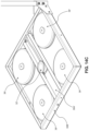
- the unmanned snow depth measuring drone subsystem comprises an aircraft body housing four vertically-mounted symmetrically arranged propeller-type rotors, supporting vertical takeoff (VTO) and pitched flight over building rooftops while (i) measuring the depth profile of snow loads on rooftops, using any one of a number of supported non-contact type methods and modules, and (ii) capturing digital video images within the field of view (FOV) of its onboard camera subsystem during its course of travel, thereby collecting information for processing and generation of GPS-indexed time-stamped snow depth profile maps of building rooftops including before, during and after snow storms, in accordance with the principles and teachings of the present invention.
- VTO vertical takeoff
- FOV field of view
- Another object of the present invention is to provide such a building intelligence gathering, assessment and decision-support system, wherein the unmanned snow depth measuring drone subsystem measures the depth profile of snow loads on rooftops, using an energy-beam based method of non-contact snow depth measurement.
- Another object of the present invention is to provide such a building intelligence gathering, assessment and decision-support system, wherein the unmanned snow depth measuring drone subsystem carries out a LIDAR based snow depth measurement method, wherein an amplitude modulated (AM) laser beam is generated and transmitted into a layer of snow, while the return laser signal is detected and processed to determine the time of flight of the laser beam to the snow, and thereby computing a measured depth of the snow on the building rooftop.
- AM amplitude modulated
- Another object of the present invention is to provide such a building intelligence gathering, assessment and decision-support system, wherein the unmanned snow depth measuring drone subsystem carries out a scanning LIDAR based snow depth measurement method, wherein an amplitude modulated (AM) laser beam is generated and scanned across a layer of snow, while the return laser signal is detected and processed to determine the time of flight of the laser beam through the snow, and thereby compute a measured depth of the snow on the building rooftop.
- AM amplitude modulated
- Another object of the present invention is to provide such a building intelligence gathering, assessment and decision-support system, wherein the unmanned snow depth measuring drone subsystem carries out an optical range finding based snow depth measurement method, wherein an LED-generated amplitude modulated light beam is generated and transmitted into a layer of snow, and the return light signal is detected and processed to determine the time of flight of the light beam through the snow, and thereby computing a measured depth of the snow on the building rooftop.
- Another object of the present invention is to provide such a building intelligence gathering, assessment and decision-support system, wherein the unmanned snow depth measuring drone subsystem carries out a RADAR based snow depth measurement method, wherein an microwave energy beam is generated and transmitted into a layer of snow, and the return microwave signal is detected and processed to determine the time of flight of the beam through the snow, and thereby computing a measured depth of the snow on the building rooftop.
- the unmanned snow depth measuring drone subsystem carries out a RADAR based snow depth measurement method, wherein an microwave energy beam is generated and transmitted into a layer of snow, and the return microwave signal is detected and processed to determine the time of flight of the beam through the snow, and thereby computing a measured depth of the snow on the building rooftop.
- Another object of the present invention is to provide such a building intelligence gathering, assessment and decision-support system, wherein the unmanned snow depth measuring drone subsystem carries out a SONAR based snow depth measurement method, wherein an acoustic energy beam is generated and transmitted into a layer of snow, and the return acoustic signal is detected and processed to determine the time of flight of the beam through the snow, and thereby computing a measured depth of the snow on the building rooftop.
- a SONAR based snow depth measurement method wherein an acoustic energy beam is generated and transmitted into a layer of snow, and the return acoustic signal is detected and processed to determine the time of flight of the beam through the snow, and thereby computing a measured depth of the snow on the building rooftop.
- Another object of the present invention is to provide such a building intelligence gathering, assessment and decision-support system, wherein the unmanned snow depth measuring drone subsystem carries out a multi-element optical range finding method of snow depth measurement of the present invention, wherein optical energy beam is generated and transmitted into a layer of snow, and the return optical signal is detected and processed along different optical channels, to determine a measured depth of the snow at particular locations on the building rooftop.
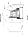
- Another object of the present invention is to provide such a building intelligence gathering, assessment and decision-support system, which further comprises a dome-type shelter system supported on a building rooftop for sheltering a remotely-controlled unmanned snow depth measuring aircraft, wherein the shelter system has a closed configuration adapted for storing a unmanned snow depth measuring aircraft system, while its battery packs are reconditioned and recharged and diagnostic analysis is carried out during periodic maintenance operations.
- Another object of the present invention is to provide such a building intelligence gathering, assessment and decision-support system, wherein the snow sheltering dome system comprises a support post, a semi-spherical base portion supporting a planar landing platform on which a unmanned snow depth measuring aircraft system can land and be supported, and a pair of hinged quarter-spherical housing portions for enclosing the aircraft system during its closed configuration and revealing the same when configured in its open configuration.
- the snow sheltering dome system comprises a support post, a semi-spherical base portion supporting a planar landing platform on which a unmanned snow depth measuring aircraft system can land and be supported, and a pair of hinged quarter-spherical housing portions for enclosing the aircraft system during its closed configuration and revealing the same when configured in its open configuration.
- Another object of the present invention is to provide such a building intelligence gathering, assessment and decision-support system, wherein the snow sheltering dome system is arrangeable in a closed mode, with its hinged housing portions closed about its unmanned snow depth measuring aircraft supported on its landing support platform;
- Another object of the present invention is to provide such a building intelligence gathering, assessment and decision-support system, wherein the snow drone sheltering dome system can be arranged in an open mode, with its hinged housing portions opened and removed away from the unmanned snow depth measuring aircraft supported on its landing support platform.
- the unmanned snow depth measuring aircraft system comprises a snow depth measurement subsystem, a flight/propulsion subsystem enabling vertical take off (VTO) flight using multi-rotor systems, a collision avoidance subsystem, an inertial navigation & guidance subsystem, a digital video imaging subsystem, a data communication subsystem, altitude measurement and control subsystem, snow depth profiling subsystems, auto-pilot subsystem, GPS navigation subsystem, and a subsystem control subsystem for controlling and/or managing the other subsystems during system operation.
- VTO vertical take off
- Another object of the present invention is to provide such a building intelligence gathering, assessment and decision-support system, wherein the unmanned snow depth measuring aircraft system profiles GPS-specified regions of the building rooftop using laser/light beam methods when no snow accumulations are present, and transferring digital information about such collected rooftop intelligence to the remote data center of system.
- Another object of the present invention is to provide such a building intelligence gathering, assessment and decision-support system, wherein the unmanned snow depth measuring aircraft system profiles GPS-specified regions of the building rooftop using laser/light beam methods when snow accumulations are present on the rooftop, and transferring digital information about such collected rooftop intelligence to the remote data center of the system.
- Another object of the present invention is to provide such a building intelligence gathering, assessment and decision-support system, wherein the unmanned snow depth measuring aircraft system profiles GPS-specified regions of the building rooftop using sonar/acoustic-based methods and real time kinematic (RTK) GPS referencing techniques (to enhance the precision of positioning) when snow accumulations are and are not present on the rooftop, and (ii) transferring digital information about such collected rooftop intelligence to the remote data center of the system, for subsequent processing to computer snow depth profile maps.
- RTK real time kinematic
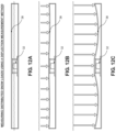
- Another object of the present invention is to provide such a building intelligence gathering, assessment and decision-support system, which further comprises an automated snow conveying tunnel system mounted on the building rooftop and having an open configuration exposing a motorized snow conveyor belt during snow loading and conveying operations.
- Another object of the present invention is to provide such a building intelligence gathering, assessment and decision-support system, wherein the automated snow conveying tunnel system comprises a conveyor belt subsystem, driven by electric and/or gas driven motors, with hydraulically-controlled tunnel sections surrounding the conveyer belt and arrangeable in a close, half-open and wide-open configurations.
- the automated snow conveying tunnel system comprises a conveyor belt subsystem, driven by electric and/or gas driven motors, with hydraulically-controlled tunnel sections surrounding the conveyer belt and arrangeable in a close, half-open and wide-open configurations.
- Another object of the present invention is to provide such a building intelligence gathering, assessment and decision-support system
- the automated snow conveying tunnel system comprises a hydraulically-powered conveyor (belt) covering subsystem, a conveyor snow belt transport subsystem, conveyor belt de-icing subsystem, digital camera subsystems providing various fields of view (FOV), LED-based illumination subsystems for illuminating these FOVs, a data communication subsystem, a temperature sensing subsystem, a conveyor belt lubrication subsystem, a VR-guided control subsystem, a GPS navigation subsystem, and a subsystem control subsystem for controlling and/or managing the operation of these subsystems during system operation.
- the automated snow conveying tunnel system comprises a hydraulically-powered conveyor (belt) covering subsystem, a conveyor snow belt transport subsystem, conveyor belt de-icing subsystem, digital camera subsystems providing various fields of view (FOV), LED-based illumination subsystems for illuminating these FOVs, a data communication subsystem, a temperature sensing subsystem,
- Another object of the present invention is to provide such a building intelligence gathering, assessment and decision-support system, wherein a first illustrative embodiment of the VR-guided (i.e. VR-navigated) snow removing robot system comprises a compact lightweight body, with a traction-type drive system powered by an electric motor (and/or fossil-fuel engine), and having a snow moving tool (e.g.
- snow shovel, snow blower, or the like movable under hydraulic control, along with weatherized digital video camera systems providing field of views (FOVs) in the front and rear of the robotic vehicle, and having multi-band wireless radio control and communications, GPS-supported navigation and collision avoidance capabilities, allowing the vehicle to be safely operated by a human operator remotely situated in front a VR-guided control station, wearing VR display goggles or viewing a stereoscopic-display panel.
- FOVs field of views
- Another object of the present invention is to provide such a building intelligence gathering, assessment and decision-support system, wherein the VR-guided snow removing robot system comprises a snow shovel tool mounted to its front end, as well as being fully equipped with side, front and rear navigational camera systems, side, front and rear ranging sensors, a GPS, a RTK antenna, a 900 MHZ antenna, and a refuel/recharging port mounted in the rear of the vehicular system.
- Another object of the present invention is to provide such a building intelligence gathering, assessment and decision-support system, wherein the VR-guided snow removing robot system comprises side, front and rear navigational camera systems, side, front and rear ranging sensors, a GPS receiver, an RTK antenna, a 900 MHZ wireless communication antenna, and a refuel/recharging port mounted in the rear of the vehicular system.
- the VR-guided snow removing robot system comprises side, front and rear navigational camera systems, side, front and rear ranging sensors, a GPS receiver, an RTK antenna, a 900 MHZ wireless communication antenna, and a refuel/recharging port mounted in the rear of the vehicular system.
- Another object of the present invention is to provide such a building intelligence gathering, assessment and decision-support system, further comprising a snow shelter system installed on a building rooftop, and adapted for protecting a snow removing robot system, from snow and other forms of harsh outdoor weather, while refueling and recharging the robot system as required to satisfy its energy/power requirements.
- Another object of the present invention is to provide such a building intelligence gathering, assessment and decision-support system, wherein a second illustrative embodiment of the VR-guided snow removing robot system comprises a snow blowing tool mounted to its front end, as well as being fully equipped with side, front and rear navigational camera systems, side, front and rear ranging sensors, a GPS receiver, an RTK antenna, a 900 MHZ antenna, and a refuel/recharging port mounted in the rear of the snow removing robot system.
- Another object of the present invention is to provide such a building intelligence gathering, assessment and decision-support system, wherein the VR-guided snow removing robot system comprises side, front and rear navigational camera systems, side, front and rear ranging sensors, a GPS receiver, an RTK antenna, a 900 MHZ antenna, and a refuel/recharging port mounted in the rear of the snow removing robot system.
- the VR-guided snow removing robot system comprises side, front and rear navigational camera systems, side, front and rear ranging sensors, a GPS receiver, an RTK antenna, a 900 MHZ antenna, and a refuel/recharging port mounted in the rear of the snow removing robot system.
- the VR-navigated snow removing robot system comprises a snow-depth measurement subsystem, a propulsion/drive subsystem, collision avoidance subsystem, digital camera subsystems providing various (i.e. front, rear and side fields of views (FOVs), LED-based illumination subsystems for illuminating these FOVs, a data communication subsystem, a temperature & moisture measurement subsystem, snow-depth profiling subsystem, a VR-guided and auto-pilot subsystem, a GPS navigation subsystem, and a subsystem control subsystem for controlling and/or managing the operation of these subsystems during system operation.
- FOVs front, rear and side fields of views
- Another object of the present invention is to provide such a building intelligence gathering, assessment and decision-support system, wherein a human operator/inspector carries a hand-held mobile augmented-reality (AR) based rooftop navigation and inspection device while standing on a building rooftop, while viewing the rooftop through the field of view (FOV) of the digital video camera aboard the hand-held rooftop navigation and inspection device, while GPS-indexed icons of rooftop-mounted snow load measuring systems/stations are displayed on the LCD display panel to assist the operator while navigating the rooftop, inspecting the situation, and identifying where snow load monitoring stations have been installed and where excessive snow loads have been automatically detected and reported to building management and maintenance team members by the system.
- AR augmented-reality
- Another object of the present invention is to provide such a building intelligence gathering, assessment and decision-support system, wherein the hand-held augmented-reality (AR) based rooftop navigation and inspection device displays graphical AR icons within the field of view of the digital camera system, and wherein the AR icons indicating the GPS location of snow load monitoring systems mounted on the rooftop, and possibly buried in snow cover.
- AR augmented-reality
- Another object of the present invention is to provide a novel method of monitoring rooftop snow loads using a mobile augmented-reality (AR)-enabled rooftop navigation and inspection system, comprising the steps of: (a) receiving a snow load alarm notification from a building intelligence gathering, assessment and decision-support system, and accessing the mobile AR-enabled rooftop navigation and inspection system, (b) holding the mobile AR-enabled rooftop navigation and inspection system in the operator's hand or as part of an VR helmet with clear projection visor, viewing the system's Field of View (FOV) while (i) observing augmented-reality (AR) images (or icons) of GPS-indexed snow load measuring stations installed on the rooftop, (ii) inspecting rooftop conditions (and showing a geo-referenced overlayed heat map image corresponding to (a) snowload, (b) load status at each SLMS or (c) snowdepth as acquired by the drone vehicle), (iii) making audio and video recordings of the rooftop, and (iv) taking notes and linking the same to the snow load alarm event, and
- Another object of the present invention is to provide an automated system for monitoring, detecting and removing excessive snow loads from building rooftop surfaces using the VR-guided snow removing robot system, guided and controlled by an remotely-situated human operator working before a snow removing robot navigation and control station supporting virtual reality (VR) and augmented-reality (AR) viewing experiences.
- VR virtual reality
- AR augmented-reality
- Another object of the present invention is to provide such a building intelligence gathering, assessment and decision-support system, comprising a virtual and augmented-reality supported snow robot navigation and control station including a stereoscopic display subsystem, a network communication subsystem, a data keyboard and mouse, a printer, an audio subsystem, a 3D controller subsystem, and a processor and memory subsystem.
- a virtual and augmented-reality supported snow robot navigation and control station including a stereoscopic display subsystem, a network communication subsystem, a data keyboard and mouse, a printer, an audio subsystem, a 3D controller subsystem, and a processor and memory subsystem.
- Another object of the present invention is to provide such a building intelligence gathering, assessment and decision-support system, wherein a virtual and augmented-reality supported snow robot navigation and control station displays split screens containing (i) the front and rear field of views (FOVs) of the digital video cameras aboard the VR-guided snow removing robot system, and (ii) the videos and images captured by the unmanned snow depth measuring aircraft system of the present invention, to help the operator safely navigate on the snow-covered rooftop during rooftop snow removal operations.
- FOVs front and rear field of views
- Another object of the present invention is to provide such a building intelligence gathering, assessment and decision-support system, wherein a first illustrative embodiment of the automated snow conveying tunnel system of the present invention is shown mounted on the building rooftop and arranged in its closed configuration sheltering its motorized snow conveyor belt from weather conditions that might otherwise cause snow piling, icing and other conditions adversely effecting the operation of snow conveying operations;
- Another object of the present invention is to provide such a building intelligence gathering, assessment and decision-support system, wherein a snow conveying tunnel system is mounted on the building rooftop and arranged in its wide-open configuration allowing a VR-guided snow removing robot system to easily load snow onto the conveyor belt of the snow conveying tunnel system and transport it off the rooftop onto the ground surface below for subsequent handling and/or processing.
- Another object of the present invention is to provide such a building intelligence gathering, assessment and decision-support system, wherein a snow load monitoring system is provided, comprising: (i) an injection-molded plastic base station designed for measuring snow load on its surface using a single load cell configured in a deflection method of measurement; (ii) a control, data processing and communication module supported on a vertical mast/post mounted to the base station; and (iii) a whip antenna terminated with a stroboscopic illumination module and flexible photo-voltaic (PV) panel wrapped about the vertical mast.
- a snow load monitoring system comprising: (i) an injection-molded plastic base station designed for measuring snow load on its surface using a single load cell configured in a deflection method of measurement; (ii) a control, data processing and communication module supported on a vertical mast/post mounted to the base station; and (iii) a whip antenna terminated with a stroboscopic illumination module and flexible photo-voltaic (PV) panel wrapped about the vertical mast.
- PV photo
- Another object of the present invention is to provide such a building intelligence gathering, assessment and decision-support system, wherein the snow load monitoring system is provided, comprising (i) an injection-molded plastic base station designed for measuring snow load on its surface using a single load cell configured in a deflection method of measurement; (ii) a control, data processing and communication module supported on a vertical mast/post mounted to the base station; and (iii) a whip antenna terminated with a stroboscopic illumination module and flexible photo-voltaic (PV) panel wrapped about the vertical mast.
- the snow load monitoring system comprising (i) an injection-molded plastic base station designed for measuring snow load on its surface using a single load cell configured in a deflection method of measurement; (ii) a control, data processing and communication module supported on a vertical mast/post mounted to the base station; and (iii) a whip antenna terminated with a stroboscopic illumination module and flexible photo-voltaic (PV) panel wrapped about the vertical mast.
- PV photo-voltaic
- Another object of the present invention is to provide such a building intelligence gathering, assessment and decision-support system, wherein a snow load monitoring system is provided, comprising: the base station supporting a wind speed and direction instrument mounted on a mast, about which a thin-film photo-voltaic (PV) panel is wrapped for solar energy collection while offering minimal wind resistance to the rooftop-mounted system, and a stroboscopic illumination module mounted on the top of the instrument.
- a snow load monitoring system comprising: the base station supporting a wind speed and direction instrument mounted on a mast, about which a thin-film photo-voltaic (PV) panel is wrapped for solar energy collection while offering minimal wind resistance to the rooftop-mounted system, and a stroboscopic illumination module mounted on the top of the instrument.
- PV photo-voltaic
- Another object of the present invention is to provide such a building intelligence gathering, assessment and decision-support system, wherein a snow load monitoring system is provided, comprising a PCB-based control and communication module mounted inside a base station, and a thin-film photo-voltaic panel mounted on the top surface of a weigh panel, while a wind speed and direction instrument and stroboscopic illumination module are mounted at the distal portion of its vertically supported mast structure, wherein during a deflection method of measuring distributed snow loads, the flexible weigh panel deflects in response to the application of a spatially-distributed snow load, and the single load mounted in the center of the base station responds to the applied snow load, and deflection of the flexible weigh panel generates electrical signals corresponding to the intensity of the distributed snow load.
- a snow load monitoring system comprising a PCB-based control and communication module mounted inside a base station, and a thin-film photo-voltaic panel mounted on the top surface of a weigh panel, while a wind speed and direction instrument and stroboscopic illumination
- Another object of the present invention is to provide a novel method of calibrating a load sensor and programming a snow load data processing module (i.e. control, data processing and communication module) based on deflection-based measurement principles of physics, comprising the steps of (a) mounting a snow load sensing module to be tested in the bottom of a box like structure wherein the walls of the box like structure spatially correspond with the perimeter boundaries of the snow load sensing surface, (b) installing a flexible fluid containing membrane over the sensor inside the box like structure, (c) adding quantified amounts of snow/ice loading material into the box, and measuring the electrical output of the sensor in the snow load sensing module, (d) correlating the depth of the snow/ice loading material with the voltage output of the sensor, (e) using the depth vs. voltage data to create a mathematical formula that provides a voltage in response to snow pressure, and (f) loading the mathematical formula into persistent (i.e. flash) memory associated with the data processing module.
- a snow load data processing module i.e. control, data
- Another object of the present invention is to provide such a building intelligence gathering, assessment and decision-support system, wherein an integrated spring mechanism provided in a snow load monitoring system mounted on a building rooftop surface, allows the mast to elastically deform and bend in response to wind forces applied to the snow load monitoring system.
- Another object of the present invention is to provide such a building intelligence gathering, assessment and decision-support system, wherein a snow load monitoring system is provided, comprising: a base plate constructed from a folded sheet metal bonded together, and a base station constructed from sheet metal using a single load cell configured using the deflection measurement method, wherein a set of disc-like weights are mounted about the load cell to provide stability in the presence of wind, and a base weigh plate supported over the base frame.
- Another object of the present invention is to provide such a building intelligence gathering, assessment and decision-support system, wherein a snow load monitoring system is provided, comprising: a PCB-based control, data processing and communication module mounted above a base station by a set of four corner-mounted fiberglass legs which designed to elastically distort and prevent overturning against high winds.
- Another object of the present invention is to provide a novel strain gauge force sensor (i.e. load cell) for use in a snow load monitoring system, comprising: an injection-molded base housing having a cylindrical load cell mounting recess; a strain-gauge sensor mounted in a mounting recess of a base housing component; co-molded cover housing portion having an elastic load sensing region disposed above in close contact with the load sensor; and a rubber gasket for insertion between the cover housing portion and the base housing portion.
- a novel strain gauge force sensor i.e. load cell
- Another object of the present invention is to provide a novel strain gauge force sensor (i.e. load cell) for use in a snow load monitoring system, comprising: an injection-molded base housing having a cylindrical load cell mounting recess; a strain-gauge sensor mounted in mounting recess of the base housing component; a co-molded cover housing portion having an elastic load sensing region disposed above in close contact with the load sensor; a rubber gasket for insertion between the cover housing portion and the base housing portion; and a base-mounted force-overload protection spring mounted between the load sensor and bottom surface of the base housing and adapted to reduce the magnitude of force that the load cell sensor experiences when excessive force overloads are applied to the elastic load sensing region of the strain gauge force sensing device.
- a novel strain gauge force sensor i.e. load cell
- Another object of the present invention is to provide a novel strain gauge force sensor (i.e. load cell) for use in a snow load monitoring system, comprising: an injection-molded base housing having a cylindrical load cell mounting recess; a strain-gauge sensor mounted in mounting cup having a pair of support flanges; a co-molded cover housing portion having an elastic load sensing region disposed above in close contact with the load sensor; a rubber gasket for insertion between the cover housing portion and the base housing portion; and a set of force-overload protection springs mounted between the support flanges and the bottom surface of the base housing and adapted to reduce the magnitude of force that the load cell sensor experiences when excessive force overloads are applied to the elastic load sensing region of the strain gauge force sensing device.
- a novel strain gauge force sensor i.e. load cell
- Another object of the present invention is to provide a novel strain gauge force sensor (i.e. load cell) for use in a snow load monitoring system, comprising load sensor supported within a mounting cup and between a pair of force-overload protection springs mounted between support flanges and the bottom of a base housing portion, to reduce the magnitude of force that the load cell sensor experiences when excessive force overloads are applied to the elastic load sensing region.
- a novel strain gauge force sensor i.e. load cell
- Another object of the present invention is to provide a novel strain gauge force sensor (i.e. load cell) for use in a snow load monitoring system, comprising a strain-gauge sensor mounted within a foam ring or rubber bellows structure between a pair of rigid plates.
- a novel strain gauge force sensor i.e. load cell
- Another object of the present invention is to provide a novel strain gauge force sensor (i.e. load cell) for use in a snow load monitoring system, comprising a piezo-gauge sensor mounted between two injection-molded plastic housing components.
- a novel strain gauge force sensor i.e. load cell
- Another object of the present invention is to provide a novel strain gauge force sensor (i.e. load cell) for use in a snow load monitoring system, comprising: a piezo-gauge sensor; a first injection-molded plastic housing component having a recess for receiving the piezo-gauge sensor, a second co-molded plastic housing component having a rubber load force region that establishes contact with the piezo-gauge sensor; and rubber gasket seal that sits in a seats formed within the first and second housing components; and a set of screws for fastening together the first and second housing components.
- a novel strain gauge force sensor i.e. load cell
- Another object of the present invention is to provide a novel snow load monitoring system comprising a base station having a force sensor recess (i.e. mounting well) stamped into a piece of sheet metal, and a weigh plate bonded or welded to the sheet metal.
- Another object of the present invention is to provide a novel snow load monitoring system comprising a base station having an extruded frame having flat top and bottom plates that slide into the extruded frame, and a force sensor is mounted in a support frame fixed to the bottom plate.
- Another object of the present invention is to provide a novel snow load monitoring system comprising an injection-molded plastic weight plate and base housing containing a single load sensor configured according to the deflection measurement method, and the mast is mounted on the side of the base station.
- Another object of the present invention is to provide a novel snow load monitoring system comprising an injection-molded plastic weight plate and base housing containing four load sensors configured according to a deflection measurement method, and a mast mounted on the center of the base station.
- Another object of the present invention is to provide a novel snow load monitoring system comprising a base station having a weight plate affixed and sealed to the base housing framework containing four load sensors configured according to a translational measurement method, and a mast mounted on the side of the base station.
- Another object of the present invention is to provide a novel snow load monitoring system comprising a base station having a flexible gasket disposed between a flat weight and base plates with four load sensors mounted on the base plate and configured according to a translational measurement method, and a mast mounted on the side of the base station.
- Another object of the present invention is to provide a novel snow load monitoring system comprising a base station comprising a weight plate, a load sensor, bathroom-scale cantilever load distribution structures and a base framework with a bottom base plate.
- Another object of the present invention is to provide a novel snow load monitoring system comprising a base station having a plurality of piezo-type load sensors molded into a rubber-like casing disposed between flat weigh and base plates.
- Another object of the present invention is to provide a novel snow load monitoring system comprising a base station having a Bluetooth® data communication link for wireless communication with a mobile smart phone running an application designed for programming and monitoring the snow load monitoring system.
- Another object of the present invention is to provide a building intelligence gathering, assessment and decision-support system, supporting various enterprise-level services on the system network including, for example, managing (i) users registered on a user account, (ii) buildings registered on a user account, (iii) zones registered on buildings on a user account, (iv) gateways registered with buildings on a user account, (v) snow load monitoring stations registered within zones of a building on a user account, (vi) VR-guided snow removing robot systems registered with Buildings on a user account, (vii) unmanned snow depth measuring aircraft systems registered with a building on a user account, and (viii) AR-based mobile rooftop navigation and inspection systems registered with a building on a user account.
- Another object of the present invention is to provide a building intelligence gathering, assessment and decision-support system, supporting various enterprise-level services (i.e. actions) on the system network including, for example, (i) poll all stations to monitor parameter settings and detected conditions, (ii) simulate snow accumulation conditions at a snow load monitoring station on a building rooftop in response to selected input conditions, (iii) visualize data collected at a particular snow load monitoring station, and (iv) review weather forecasts at particular building rooftops.
- enterprise-level services i.e. actions
- Another object of the present invention is to provide a building intelligence gathering, assessment and decision-support system, supporting the polling of all snow load monitoring stations to monitor parameter settings and detected conditions at each polled snow load monitoring station.
- Another object of the present invention is to provide a building intelligence gathering, assessment and decision-support system, supporting various enterprise-level services on the system network including (i) building rooftop snow depth profiling using an unmanned snow depth measuring aircraft system, (ii) reviewing building rooftop snow depth profile models maintained and periodically updated by the system, and (iii) forecasting weather conditions for a specified building.
- Another object of the present invention is to provide a novel method of rooftop snow depth profiling using unmanned snow depth measuring aircraft systems deployed within a building intelligence gathering and decision-support system, comprising the steps of: (a) deploying a unmanned snow depth measuring aircraft system registered with the BIGADS system, to profile the snow depth of a particular building rooftop, (b) selecting and enabling a non-contact unmanned snow depth measuring method on the unmanned snow depth measuring aircraft system, (c) collecting GPS-indexed snow depth profile data from the building rooftop, (d) transmitting collected GPS-indexed snow depth to the database server of the data center of the BIGADS system, and (d) using a Web browser to request and review snow depth profile data for a specified building rooftop.
- Another object of the present invention is to provide a building intelligence gathering, assessment and decision-support system, supporting method of forecasting the weather conditions at locations of specific buildings registered on a user account on the system network, comprising the steps of: (a) accessing and processing historical weather data recorded in weather databases and creating a building weather database for a particular building being managed by the BIGADS system; (b) collecting and storing local weather data from rooftop-mounted snow load measuring stations and adding this data to the building weather database for the specified building registered in the BIGADS system; (c) collecting GPS-indexed snow depth profile data from the building rooftop, and add this snow depth profile data to the building weather database; (d) analyzing the data contained in the building weather database to identify patterns and trends useful for predicting and weather forecasting; and (e) using a web browser to request weather forecast reports based on data collected and processed in the building weather database, and using such reports to plan a course of action relating to expected requirements of rooftop snow load management during a particular time period.
- Another object of the present invention is to provide a method of designing, installing, deploying and operating an automated building rooftop snow load monitoring and removal system, comprising the steps of comprising: (a) during a pre-design and pre-installation phase, surveying and modeling rooftop building conditions; (b) during a design phase, developing 3D Rooftop Geometry Model (3DRGM) specifying various rooftop building parameters (i.e. rooftop boundary conditions, snow load measurement zones rated in pressure (i.e. 30 PSF), structures (e.g.
- 3DRGM 3D Rooftop Geometry Model
- Another object of the present invention is to provide a method of detecting, communicating, responding to, and resolving snow load alarm conditions on a building associated with a user account on the system network of a building intelligence gathering, assessment and decision-support system, comprising the steps: of (a) deploying a plurality of snow load monitoring systems on the surface of a specified building rooftop and configuring these SLMSs to the system network of the system; (b) deploying a VR-guided snow removing robot system on the surface of a specified building rooftop and configuring the snow removing robot system to the system network of the system; (c) deploying a VR-enabled control station for remotely operating the snow removing robot system on the surface of the specified building rooftop and configuring the VR-enabled control station to system network of the system; (d) registering a team of building management and/maintenance members with a User Account maintained on the system network of the system; (e) in response to at least one of the snow load monitoring system automatically detecting a snow load at a specified region of the
- Another object of the present invention is to provide method of responding to snow load alarm notifications by making physical rooftop inspections using the hand-held AR-guided rooftop navigation and inspection systems of the present invention, comprising the steps of: (a) receiving a snow load alarm notification from the building intelligence gathering, assessment processing and decision-support system; (b) using a hand-held AR-enabled rooftop navigation and inspection system to navigate and inspect the building rooftop specified in the snow load alarm notification; (c) recording the navigation and inspection of the building rooftop, including recorded annotations by the human operator/building inspector, and transmitting the annotated video recording to a database server maintained at the data center of the system; and (d) others on the building management and maintenance team using a Web browser to access the database server and review the annotated recording of the building rooftop inspection report made by the inspector using the AR-enabled rooftop navigation and inspection system.
- Another object of the present invention is to provide a method of responding to snow load alarm notifications by deploying a snow load measuring aircraft system to the building for remote aerial inspection and rooftop intelligence collection operations for review by remotely situated building managers, comprising the steps of: (a) a building management team member receiving a snow load alarm notification from a building intelligence gathering, assessment processing and decision-support system; (b) deploying an unmanned snow depth measuring aircraft system registered with the building, to navigate and inspect the building rooftop specified in the snow load alarm notification and compare snow depth measurements against measured snow load conditions at the specified rooftop location; (c) capturing a digital video recording and snow depth measurements around and about the snow load alarm region, and transmitting the recording to a database server maintained at the data center of the system; and (d) others on the building management and maintenance team using a Web browser to access the database server and review the recording of the aerial building rooftop inspection made by the flying unmanned snow depth measuring aircraft system over the specified building rooftop.
- Another object of the present invention is to provide a method of removing specified snow loads on a rooftop using VR-guided robotically-controlled snow collection and removal systems (i.e. machines) remotely controlled and operated by a human operator using a remotely-located VR/AR-enabled control station configured for remotely controlling the operation of the snow collecting and removing robot system on the building rooftop, comprising the steps of: (a) installing VR-guided snow removing robot system on building rooftop, and configuring at least one VR-Guided robot navigation and control station with the building intelligence gathering, assessment and decision-support system of the present invention; (b) receiving a rooftop snow load condition message from the building intelligence gathering, assessment and decision-support system; (c) using the VR-guided robot navigation and control station to remotely control the VR-guided snow removing robot system on the building rooftop and remove the identified rooftop snow load condition specified in the rooftop snow load condition message; (d) sending a rooftop snow load condition removal notification from the VR-guided robot navigation and control station to the building intelligence gathering, assessment and decision-support system; (e
- Another object of the present invention is to provide a method of removing specified snow loads on a rooftop using AI-guided robotically controlled snow collection and removal systems (i.e. machines) remotely controlled and operated by an artificial intelligence (AI) based navigational control server comprising the steps of: (a) installing at least one AI-guided snow removing robot system on building rooftop, and configuring an AI-based navigation control server within the system network of the building intelligence gathering, assessment and decision-support system of the present invention; (b) receiving a rooftop snow load condition message from the building intelligence gathering, assessment and decision-support system; (c) using the AI-based navigation control server to remotely control the AI-guided snow removing robot system on building rooftop and remove the identified rooftop snow load condition specified in the rooftop snow load condition message; (d) sending a rooftop snow load condition removal notification from the AI-based navigation control server supported within the building intelligence gathering, assessment and decision-support system; (e) the building intelligence gathering, assessment and decision-support system transmitting the rooftop snow load condition removal notification to members of the building management team; and (f) the
- Another object of the present invention is to provide a new and improved system of reconfigurable rooftop-based snow conveying machines which can be quickly and remotely reconfigured so as to optimally support the automated and/or semi-automated removal of rooftop snow loads, using other machinery such as remotely control snow removing robots equipped with various types of snow-removal tools such as, snow pushers, snow scoopers, snow blowers, and the like.
- Another object of the present invention is to provide such a novel Internet-based method of and system for gathering, assessing and sharing information and media relating to building rooftop conditions for supporting building managers, maintenance workers and others in their effort to maintain building property and the security of those who live and work in building spaces.
- Another object of the present invention is to provide a novel Internet-based system network that comprises client application software for mobile devices, tablets and desktops, and supports a communication and message processing infrastructure that allows conventional mobile phones supporting SMS and/or email to share captured snow depth profiles with building management team members and property managers using the client application software on their smart phone devices.
- Another object of the present invention is to provide a novel Internet-based system network enabling geographically, distributed building management team members to actively and meaningfully contribute to the decisions required to support building property management operations.
- Another object of the present invention is to provide a novel Internet-based system network enabling remote-situated building management team members to share insights and make suggestions during emergency decisions created by excessive snow load conditions on building rooftops presenting great risk to property damage, business disruption, and human safety.
- Another object of the present invention is to provide a novel Internet-based system network that is realized using desktop, tablet and mobile HTML5 applications that allow system network users to easily collect, store and share building rooftop intelligence, including rooftop snow depth, GPS-indexed snow load measurements, and related video media with building management team members, however distributed, to help support them in their daily decision making operations.
- FIG. 1 A shows the building intelligence gathering, assessment and decision-support (BIGADS) system of the present invention deployed across a portfolio of buildings, on the rooftops of which an automated building rooftop snow removal system (ABRSRS) is configured and deployed, comprising (i) a wireless network of snow load monitoring stations (SLMS), (ii) VR-guided snow removing robot systems, (iii) automated snow conveying tunnel systems, (iv) VR/AR-enabled control stations for remotely controlling the operation of VR-guided snow removing robot systems during rooftop snow removal operations, (v) unmanned flying snow depth measuring aircraft systems (i.e.
- SLMS snow load monitoring stations
- VR-guided snow removing robot systems iii)
- automated snow conveying tunnel systems automated snow conveying tunnel systems
- VR/AR-enabled control stations for remotely controlling the operation of VR-guided snow removing robot systems during rooftop snow removal operations
- unmanned flying snow depth measuring aircraft systems i.e.
- drones having high-resolution digital video image capturing and transmission capabilities
- VR/AR-enabled control stations for remotely controlling the operation of VR-guided snow depth measuring aircraft systems during rooftop snow depth measuring, profiling and surveying operations, including digital video image capturing operations, wherein all such subsystems being integrated with and in communication with the data center and internet (TCP/IP) infrastructure of the building intelligence collection, processing and information management system of the present invention, and are tracked in real-time using a GPS referencing system;
- TCP/IP data center and internet
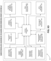
- FIG. 1 B is a high-level network diagram showing the primary components of system network supporting the BIGADS system of the present invention reflected in FIG. 1 A including building networks with client and server systems interconnected therewith via TCP/IP, the data center of the system network of the present invention, cellular phone and SMS messaging systems deployed on the Internet, Web-enabled client machines (e.g. mobile computers, smartphones, laptop computers, workstation computers, etc.), email server systems, hand-held VR-enabled rooftop navigation and inspection devices, AR/VR-enabled control stations for remotely controlling VR-navigated and controlled snow removing robot systems deployed on building rooftops, and web, application and database servers of information sources such as weather forecasting, social media, financial markets, and the like;
- Web-enabled client machines e.g. mobile computers, smartphones, laptop computers, workstation computers, etc.
- email server systems e.g. mobile computers, smartphones, laptop computers, workstation computers, etc.
- AR/VR-enabled control stations for remotely controlling VR-navigated and controlled
- FIG. 1 C is a high-level network diagram showing the various client systems and users thereof connected to the system network supporting the BIGADS system of the present invention reflected in FIG. 1 A including, for example, (i) Web-enabled client machines (e.g. mobile computers, smartphones, laptop computers, workstation computers, etc.), (ii) hand-held VR/AR-enabled rooftop navigation and inspection devices for rooftop navigation, inspection and intelligence collection, storage and sharing, (iii) AR/VR-enabled control stations for remotely controlling VR-navigated and controlled snow removing robot systems deployed on building rooftops, (iv) AR/VR-enabled control stations for remotely controlling VR-navigated and controlled snow depth measuring aircraft systems deployed at specified building rooftops, and web, application and database servers of information sources such as weather forecasting, social media, financial markets, and the like;
- Web-enabled client machines e.g. mobile computers, smartphones, laptop computers, workstation computers, etc.
- AR/VR-enabled rooftop navigation and inspection devices for rooftop navigation, inspection
- FIG. 1 D illustrates the system architecture of an exemplary mobile client system (e.g. device) deployed on the system network of the present invention and supporting the many services offered by system network servers;
- exemplary mobile client system e.g. device
- FIG. 2 A is a schematic network diagram illustrating in greater detail a network of snow load monitoring systems (SLMS) deployed on a building rooftop as shown in FIG. 1 A , illustrating the use of conventional networking technologies to interconnect these wireless subsystems into subnetworks and connect these subnetworks to the internet infrastructure of the BIGADS system of the present invention;
- SLMS snow load monitoring systems
- FIG. 2 B is a schematic diagram illustrating the flow of various streams of intelligence (i.e. information) gathered by the communication, application and database servers in the data center of the BIGADS system, from the various subsystems that collect building rooftop intelligence, including, for example, rooftop snow load monitoring systems, unmanned snow depth measuring aircraft systems (i.e. drones), weather intelligence servers (e.g. weather reporting and forecasting services), mapping intelligence servers (e.g. map services), hand-held VR-enabled rooftop navigation and inspection systems, unmanned snow removing robot systems, unmanned snow conveying tunnel systems, and VR-enabled control stations;
- rooftop snow load monitoring systems i.e. drones
- weather intelligence servers e.g. weather reporting and forecasting services
- mapping intelligence servers e.g. map services
- hand-held VR-enabled rooftop navigation and inspection systems unmanned snow removing robot systems, unmanned snow conveying tunnel systems, and VR-enabled control stations
- unmanned snow depth measuring aircraft systems i.e. drones
- weather intelligence servers e.
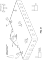
- FIG. 3 A is a perspective view of a generalized embodiment of the snow load monitoring system (i.e. station) of the present invention deployed on a GPS-indexed region of a building rooftop, as illustrated in FIG. 1 A , while networked with the wireless communication network deployed on the rooftop;
- the snow load monitoring system i.e. station
- FIG. 3 B is a perspective view of a first illustrative embodiment of the snow load monitoring system (i.e. station) of the present invention, shown comprising a gravitational force (GF) load sensing base station containing load sensors, and a communication and control (i.e. data processing) module mounted on a vertical support post, supporting a digital wind speed and direction and direction instrument (i.e. digital anemometer) connected to the communication and control module, and with a whip-type antenna extending from the communication and control (i.e. data processing) module and terminating in a stroboscopic LED-based illumination module to help human inspectors and workers visibly see the snow load measuring system mounted on the rooftop during deep snow accumulations and blustery snow conditions;
- GF gravitational force
- a communication and control (i.e. data processing) module mounted on a vertical support post, supporting a digital wind speed and direction and direction instrument (i.e. digital anemometer) connected to the communication and control module, and with a whip-type antenna
- FIG. 3 C is a block schematic diagram of the first illustrative embodiment of the snow load monitoring system of the present invention shown in FIG. 3 B , comprising various subsystems including a snow load sensing and measurement subsystem, a temperature measurement subsystem, a wind speed and direction measurement subsystem, a digital image and video capture and processing subsystem, a snow drone docking and battery charging subsystem, a data communication subsystem, a solar-powered battery storage recharging subsystem, a collision avoidance signaling subsystem for communication with snow removing and drone-based snow depth measuring subsystems, a stroboscopic visual signaling subsystem (for human rooftop inspectors), and a GPS-based referencing subsystem, all of which are integrated about a control subsystem, as shown, for controlling and managing the operations of the subsystems during system operation;
- various subsystems including a snow load sensing and measurement subsystem, a temperature measurement subsystem, a wind speed and direction measurement subsystem, a digital image and video capture and processing subsystem, a snow drone dock
- FIG. 3 D is a schematic block diagram showing an illustrative embodiment or realization of the snow load monitoring system of the first illustrative embodiment shown in FIG. 3 C , wherein various components are arranged and configured about a microprocessor and flash memory (i.e. control subsystem), including load cells, a GPS antenna, a GPS signal receiver, voltage regulator, an Xbee antenna, an Xbee radio transceiver, a voltage regulator, a photo-voltaic (PV) panel, an external power connector, a charge controller, a battery, thermistors, a power switch, a voltage regulator, external and internal temperature sensors, power and status indicator LEDs, programming ports, a wind speed and direction sensor, a digital/video camera, and other sensors, as shown;
- a microprocessor and flash memory i.e. control subsystem
- load cells including load cells, a GPS antenna, a GPS signal receiver, voltage regulator, an Xbee antenna, an Xbee radio transceiver, a voltage regulator,
- FIG. 4 A 1 is a perspective view of an airborne/flying unmanned snow depth measuring (SDM) drone subsystem illustrated in FIGS. 1 A and 2 A , shown comprising an aircraft body housing four vertically-mounted symmetrically arranged propeller-type rotors, supporting vertical takeoff (VTO) and pitched flight over building rooftops while (i) measuring the depth profile of snow loads on rooftops, using any one of the non-contact type methods and modules illustrated in FIG.
- SDM snow depth measuring
- FIG. 4 A 2 is a schematic representation illustrating six different types of energy-beam based methods of non-contact snow depth measurement that are supportable within the flying unmanned snow depth measuring aircraft subsystem (i.e. drone) illustrated in FIGS. 1 A, 2 A and 4 A 1 , either alone or in combination with each other, as illustrated in FIGS. 5 B 1 through 5 B 6 ;
- flying unmanned snow depth measuring aircraft subsystem i.e. drone
- FIG. 4 B 1 is a subsystem block diagram showing the primary functional blocks employed in the module used to carry out the LIDAR based snow depth measurement method of the present invention, wherein an amplitude modulated (AM) laser beam is generated and transmitted into a layer of snow, while the return laser signal is detected and processed to determine the time of flight of the laser beam through the snow, and thereby computing a measured depth of the snow on the building rooftop;
- AM amplitude modulated
- FIG. 4 B 2 is a subsystem block diagram showing the primary functional blocks employed in the module used to carry out the scanning LIDAR based snow depth measurement method of the present invention, wherein an amplitude modulated (AM) laser beam is generated and scanned across a layer of snow, while the return laser signal is detected and processed to determine the time of flight of the laser beam through the snow, and thereby compute a measured depth of the snow on the building rooftop;
- AM amplitude modulated
- FIG. 4 B 3 is a subsystem block diagram showing the primary functional blocks employed in the module used to carry out the optical range finding based snow depth measurement method of the present invention, wherein an LED-generated amplitude modulated light beam is generated and transmitted into a layer of snow, and the return light signal is detected and processed to determine the time of flight of the light beam through the snow, and thereby computing a measured depth of the snow on the building rooftop;
- FIG. 4 B 4 is a subsystem block diagram showing the primary functional blocks employed in the module used to carry out the RADAR based snow depth measurement method of the present invention, wherein an microwave energy beam is generated and transmitted into a layer of snow, and the return microwave signal is detected and processed to determine the time of flight of the beam through the snow, and thereby computing a measured depth of the snow on the building rooftop;
- FIG. 4 B 5 is a subsystem block diagram showing the primary functional blocks employed in the module used to carry out the SONAR based snow depth measurement method of the present invention, wherein an acoustic energy beam is generated and transmitted into a layer of snow, and the return acoustic signal is detected and processed to determine the time of flight of the beam through the snow, and thereby computing a measured depth of the snow on the building rooftop;
- FIG. 4 B 6 is a subsystem block diagram showing the primary functional blocks employed in the module used to carry out the multi-element optical range finding method of snow depth measurement of the present invention, wherein an optical energy beam is generated and transmitted into a layer of snow, and the return optical signal is detected and processed along different optical channels, to determine a measured depth of the snow at particular locations on the building rooftop;
- FIG. 4 C is a system block diagram for the unmanned snow depth measuring aircraft system of the present invention illustrated in FIGS. 4 A 1 and 4 A 2 , comprising a number of subsystems including a snow depth measurement subsystem, a flight/propulsion subsystem enabling vertical takeoff (VTO) flight using multi-rotor systems, a collision avoidance subsystem, an inertial navigation & guidance subsystem, a digital imaging (i.e. video camera) subsystem, a data communication subsystem, an altitude measurement and control subsystem, snow depth profiling subsystems, an auto-pilot subsystem, a GPS navigation subsystem, and a control subsystem for controlling and/or managing the other subsystems during system operation;
- FIG. 4 D 1 is a perspective view of a building in which the BIGADS system of the present invention has been deployed, and showing dome-type shelter system supported on the building rooftop for sheltering a remotely-controlled unmanned snow depth measuring aircraft, wherein the shelter system is shown arranged in its closed configuration and adapted for storing a unmanned snow depth measuring aircraft (drone) system (SDMAS) of the present invention, while its battery packs are reconditioned and recharged and diagnostic analysis is carried out during periodic maintenance operations;
- drone unmanned snow depth measuring aircraft
- FIG. 4 D 2 is an exploded view of the snow sheltering dome system of the present invention comprising a support post, a semi-spherical base portion supporting a planar landing platform on which a unmanned snow depth measuring aircraft system can land and be supported, and a pair of hinged quarter-spherical housing portions for enclosing the aircraft system during its closed configuration and revealing the same when configured in its open configuration;
- FIG. 4 D 3 is a perspective enlarged view of the building shown in FIG. 4 D 1 , showing the snow drone sheltering dome system of the present invention arranged in its closed mode, with its hinged housing portions closed about its unmanned snow depth measuring aircraft supported on its landing support platform;
- FIG. 4 D 4 is a perspective enlarged view of the building shown in FIG. 4 D 1 , showing the snow drone sheltering dome system of the present invention arranged in its open mode, with its hinged housing portions opened and removed away from the unmanned snow depth measuring aircraft supported on its landing support platform;
- FIG. 4 E is a perspective enlarged view of the snow drone sheltering dome system of the present invention arranged in its open mode and supported on the ground alongside a building being monitored by the BIGADS system of the present invention;
- FIGS. 4 F 1 , 4 F 2 and 4 F 3 show a perspective view of a building being monitored by the BIGADS system of the present invention, wherein the unmanned snow depth measuring aircraft system of the present invention illustrated in FIGS. 4 A 1 and 4 A 2 is profiling GPS-specified regions of the building rooftop using laser/light beam methods when no snow accumulations are present, and transferring digital information about such collected rooftop intelligence to the communication, application and database servers maintained at the remote data center of the BIGADS system illustrated in FIGS. 1 , 1 A and 1 B ;
- FIGS. 4 G 1 and 4 G 2 show a perspective view of a building being monitored by the BIGADS system of the present invention, wherein the unmanned snow depth measuring aircraft system illustrated in FIGS. 4 A 1 and 4 A 2 is shown profiling GPS-specified regions of the building rooftop using laser/light beam methods when snow accumulations are present on the rooftop, and transferring digital information about such collected rooftop intelligence to the communication, application and database servers maintained at the remote data center of the BIGADS system illustrated in FIGS. 1 , 1 A and 1 B ;
- FIG. 4 H 1 shows a perspective view of a building being monitored by the BIGADS system of the present invention, wherein the unmanned snow depth measuring aircraft system illustrated in FIGS. 4 A 1 and 4 A 2 is shown (i) profiling GPS-specified regions of the building rooftop using sonar/acoustic-based methods and real time kinematic (RTK) GPS referencing techniques (to enhance the precision of positioning) when snow accumulations are not present on the rooftop, and (ii) transferring digital information about such collected rooftop intelligence to the remote data center of BIGADS system;
- RTK real time kinematic
- FIG. 4 H 2 shows a perspective view of a building being monitored by the BIGADS system of the present invention, wherein the unmanned snow depth measuring aircraft system illustrated in FIGS. 4 A 1 and 4 A 2 is shown profiling GPS-specified regions of the building rooftop using sonar/acoustic-based methods and real time kinematic (RTK) GPS referencing techniques when snow accumulations are present on the rooftop, and transferring digital information about such collected rooftop intelligence to the remote data center of BIGADS system;
- RTK real time kinematic
- FIG. 5 A is a perspective view of one mobile automated snow conveying tunnel system (ASCTS) of the present invention shown supported on the building rooftop illustrated in FIGS. 1 and 2 A , in communication with a GPS system, RTK reference station, internet gateway and a cellular phone and SMS messaging system during snow loading and conveying operations, and having conveyor belt supported on snow-treading tracks propelled by its onboard propulsion subsystem, controlled by an onboard navigation and control subsystem remotely managed on the system network of the present invention;
- ASCTS automated snow conveying tunnel system
- FIG. 5 B is a block subsystem diagram for the automated snow conveying tunnel systems of the present invention illustrated in FIG. 5 A , shown comprising an optional hydraulically-powered conveyor belt covering subsystem, a conveyor snowbelt (snow-tractor-based) transport subsystem, conveyor belt de-icing subsystem, a plurality of digital camera subsystems providing various fields of view (FOV), a plurality of LED-based illumination subsystems for illuminating these FOVs, a data communication subsystem, a temperature sensing subsystem, a conveyor belt lubrication subsystem, a VR-guided control subsystem, a GPS navigation subsystem, and a subsystem control subsystem for controlling and/or managing the operation of these subsystems during system operation;
- FOV fields of view
- FIGS. 5 C 1 A and 5 C 1 B show top and bottom perspective views of the mobile automated snow conveying tunnel system (ASCTS) of FIG. 5 B , showing its pair of rotatably mounted propulsion tractors mounted beneath and at opposite ends of the conveyer belt structure of the present invention;
- ASCTS mobile automated snow conveying tunnel system
- FIGS. 5 C 2 A and 5 C 2 B show top and bottom side perspective views of the mobile automated snow conveying tunnel system (ASCTS) of FIG. 5 B , showing its pair of rotatably mounted propulsion tractors mounted beneath and at opposite end of the conveyer belt structure of the present invention, arranged in different configurations;
- ASCTS mobile automated snow conveying tunnel system
- FIG. 5 D is a perspective view of the mobile automated snow conveying tunnel system (MASCTS) of FIG. 5 A supported on a building rooftop surface, and provided with labeled references, namely, “longitudinal axis”, “lateral axis”, “low track drive rotation axis”, “high track drive rotation axis”, “high end” and “low end”;
- MASCTS mobile automated snow conveying tunnel system
- FIGS. 5 E 1 , 5 E 2 , 5 E 3 , 5 E 4 , 5 E 5 and 5 E 6 shows a set of plan views of the mobile automated snow conveying tunnel system (MASCTS) of the present invention showing how during States 1 and 2, both the high and low track drives of the system are rotated about their track drive rotation axes, and then during States 4 and 5, the track drives rotate the conveyor belt structure about the central vehicle rotation axis so at State 6, the conveyor belt is arranged perpendicular to its original position/orientation shown in State 1;
- MASCTS mobile automated snow conveying tunnel system
- FIGS. 5 F 1 , 5 F 2 , 5 F 3 , 5 F 4 , 5 F 5 and 5 F 6 shows a set of plan views of the mobile automated snow conveying tunnel system (MASCTS) of the present invention showing how during States 1, 2 and 3, only the high track drive is rotated about its track drive rotation axis, and then during States 4 and 5, the high track drive rotates the conveyor belt structure about the “low” track drive rotation axis so at State 6, the conveyor belt is arranged perpendicular to its original position/orientation shown in State 1, relative to the low track drive rotation axis;
- MASCTS mobile automated snow conveying tunnel system
- FIGS. 5 G 1 and 5 G 2 shows a set of plan views of the mobile automated snow conveying tunnel system (MASCTS) of the present invention showing how the conveyor belt system moves in a lateral translation manner by having the low and high drive tracks arranged orthogonal to the longitudinal axis, then moving together to achieve lateral translation of the conveyor belt structure, as shown;
- MASCTS mobile automated snow conveying tunnel system
- FIGS. 5 H 1 and 5 H 2 shows a set of plan views of the mobile automated snow conveying tunnel system (MASCTS) of the present invention showing how the conveyor belt system moves in a longitudinal translation manner by having the low and high drive tracks arranged in a co-axial manner to the longitudinal axis, then moving together to achieve longitudinal translation of the conveyor belt structure, as shown;
- MASCTS mobile automated snow conveying tunnel system
- FIG. 5 I is a first perspective view of the mobile automated snow conveying tunnel system (MASCTS) of the present invention showing on a building rooftop, with snow being loaded on the conveyor belt using a snow moving robot system as shown in FIGS. 5 N through 5 Q 2 ;
- MASCTS mobile automated snow conveying tunnel system
- FIG. 5 J is a perspective view of three (3) mobile automated snow conveying tunnel systems (MASCTS) of the present invention shown supported on the building rooftop, and arranged in a first straight-type configuration, and cooperating together to assist in removing snow from the building rooftop;
- MASCTS mobile automated snow conveying tunnel systems
- FIG. 5 K is a perspective view of three (3) mobile automated snow conveying tunnel systems (ASCTS) of the present invention shown supported on the building rooftop, and arranged in a second straight-type configuration, and cooperating together to assist in removing snow from the building rooftop;
- ASCTS automated snow conveying tunnel systems
- FIG. 5 L is a perspective view of three (3) mobile automated snow conveying tunnel systems (MASCTS) of the present invention shown supported on the building rooftop, and arranged in a second T-type configuration, and cooperating together to assist in removing snow from the building rooftop;
- MASCTS mobile automated snow conveying tunnel systems
- FIG. 5 M 1 is a perspective view of the mobile automated snow conveying tunnel system (MASCTS) of FIG. 5 L shown transporting snow off the rooftop to the ground below for collection by an automated snow moving robot system of the present invention, shown in FIGS. 5 N through 5 Q 2 ;
- MASCTS mobile automated snow conveying tunnel system
- FIG. 5 M 2 is a perspective view of the mobile automated snow conveying tunnel system (ASCTS) of FIG. 5 L shown transporting snow off the rooftop and into snow collection/dump truck on the ground below, used during semi-automated rooftop snow removal operations;
- ASCTS mobile automated snow conveying tunnel system
- FIG. 5 N is a front perspective view of a first illustrative embodiment of the VR-guided (i.e. VR-navigated) snow removing robot system of the present invention represented in FIGS. 1 and 2 A , and shown comprising a compact lightweight body, with a traction-type drive system powered by an electric motor (and/or fossil-fuel engine), and having a snow moving tool (e.g.
- snow shovel, snow blower, or the like movable under hydraulic control, along with weatherized digital video camera systems providing field of views (FOVS) in the front and rear of the robotic vehicle, and having multi-band wireless radio control and communications, GPS-supported navigation and collision avoidance capabilities, allowing the vehicle to be safely operated by a human operator remotely situated in front a VR-guided workstation, wearing VR display goggles or viewing a stereoscopic-display panel, as illustrated in FIG. 7 A through 7 B 3 ;
- FIG. 5 O is a block subsystem diagram for the VR-navigated snow removing robot systems of the present inventions illustrated in FIGS. 5 N , 5 P 1 , 5 P 2 , 5 E 3 , 5 Q 1 and 5 Q 2 , shown comprising a snow-depth measurement subsystem, a propulsion/drive subsystem, collision avoidance subsystem, digital camera subsystems providing various (i.e.
- FOVs front, rear and side fields of views
- LED-based illumination subsystems for illuminating these FOVs
- a data communication subsystem for illuminating these FOVs
- a temperature & moisture measurement subsystem for illuminating these FOVs
- snow-depth profiling subsystem for illuminating these FOVs
- a VR-guided and auto-pilot subsystem for adjusting the attitude of these subsystems during system operation
- a control subsystem for controlling and/or managing the operation of these subsystems during system operation
- FIG. 5 P 1 is a first rear perspective view of the VR-guided snow removing robot system of the present invention depicted in FIG. 5 N , showing its snow shovel tool mounted to its front end, as well as being fully equipped with side, front and rear navigational camera systems, side, front and rear ranging sensors, a GPS receiver, RTK antenna, a 900 MHZ antenna, and a refuel/recharging port mounted in the rear of the system;
- FIG. 5 P 2 is a second rear perspective view of the VR-guided snow removing robot system of the present invention depicted in FIG. 5 N , showing side, front and rear navigational camera systems, side, front and rear ranging sensors, a GPS receiver, RTK antenna, a 900 MHZ antenna, and refuel/recharging port mounted in the rear of the system;
- FIG. 5 P 3 is a top perspective view of the VR-guided snow removing robot system of the present invention depicted in FIG. 5 N , showing side, front and rear navigational camera systems, side, front and rear ranging sensors, a GPS receiver, a RTK antenna, a 900 MHZ antenna, and refuel/recharging port mounted in the rear of the system;
- FIG. 5 P 4 is a perspective view of a building rooftop involved in the BIGADS system of the present invention, showing the snow shelter system of the present invention installed on the rooftop, and adapted for protecting the snow removing robot system of FIG. 5 N , from snow and other forms of harsh outdoor weather, while refueling and recharging the robot system as required to satisfy its energy/power requirements;
- FIG. 5 P 5 is a perspective view of the snow shelter system of the present invention shown installed on the rooftop in FIG. 5 P 4 , wherein a snow removing robot system shown in FIG. 5 N is parked out of the reach of snow and other forms of harsh outdoor weather, while the refueling and recharging ports of the robot system are docked with the refueling/recharging port of the snow shelter system;
- FIG. 5 P 6 is a perspective view of the snow shelter system of the present invention shown installed on the rooftop in FIG. 5 P 4 , wherein no snow removing robot system is parked, revealing the refueling/recharging port of the snow shelter system;
- FIG. 5 Q 1 is a rear perspective view of a second illustrative embodiment of the VR-guided snow removing robot system of the present invention, showing a snow blowing tool mounted to its front end, as well as being fully equipped with side, front and rear navigational camera systems, side, front and rear ranging sensors, a GPS receiver, a RTK antenna, a 900 MHZ antenna, and a refuel/recharging port mounted in the rear of the vehicular system;
- FIG. 5 Q 2 is a front perspective view of the VR-guided snow removing robot system of the present invention depicted in FIG. 5 Q 1 , showing side, front and rear navigational camera systems, side, front and rear ranging sensors, a GPS receiver, a RTK antenna, a 900 MHZ antenna, and a refuel/recharging port mounted in the rear of the vehicular system;
- FIG. 6 A is a schematic representation of a building rooftop registered in the BIGADS system of the present invention, and on which a human operator/inspector, carrying a hand-held mobile augmented-reality (AR) based rooftop navigation and inspection system shown in FIG. 6 C , is standing and viewing the rooftop through the field of view (FOV) of the digital video camera aboard the hand-held rooftop navigation and inspection system, while GPS-indexed icons of rooftop-mounted snow load measuring stations are displayed on the LCD display panel to assist the operator while navigating the rooftop, inspecting the situation, and identifying where snow load monitoring stations (SLMS) have been installed and where excessive snow loads have been automatically detected and reported to building management and maintenance team members by the BIGADS system;
- SLMS snow load monitoring stations
- FIG. 6 A 1 is a perspective view of the hand-held augmented-reality (AR) based rooftop navigation and inspection system of the present invention, shown in FIG. 6 A ;
- AR augmented-reality
- FIG. 6 B is a subsystem block schematic diagram of the mobile augmented-reality (AR) based rooftop navigation and inspection system illustrated in FIGS. 6 A and 6 A 1 ;
- AR augmented-reality
- FIG. 6 C is a schematic representation of an exemplary display screen of the augmented-reality (AR) based rooftop navigation and inspection system illustrated in FIGS. 6 A and 6 A 1 , showing AR images containing graphical icons indicating the GPS location of snow load monitoring systems mounted on the rooftop, and possibly buried in snow cover;
- AR augmented-reality
- FIG. 6 D is a flow chart describing the primary steps involved when carrying out the method monitoring rooftop snow loads using the mobile augmented-reality (AR) based rooftop navigation and inspection system illustrated in FIGS. 6 A and 6 A 1 , comprising the steps of (a) receiving a snow load alarm notification from the BIGADS system, and accessing a hand-held AR-guided rooftop navigation and inspection device of the present invention, (b) holding the hand-held AR-guided rooftop navigation and inspection device on the operator's hand, viewing the device's Field of View (FOV) while (i) observing augmented reality (AR) icons of GPS-indexed snow load measuring stations, (ii) inspecting rooftop conditions, (iii) making audio and video recordings of the rooftop, and (iv) taking notes and linking the same to the snow load alarm event, and (c) sending the operator's snow load event inspection report to the building management and maintenance team members, and determine a plan of resolution for the snow load alarm event (e.g. make and execute a snow removal plan);
- FIG. 7 A is a schematic representation of an automated system for monitoring, detecting and removing excessive snow loads from building rooftop surfaces using the VR-guided snow removing robot system of the present invention, guided and controlled by an remotely-situated human operator working before an snow removing robot navigation and control station supporting virtual reality (VR) and augmented-reality (AR) viewing experiences, as illustrated in FIG. 7 B 3 ;
- VR virtual reality
- AR augmented-reality
- FIG. 7 B 1 is a block subsystem diagram of the virtual and augmented reality supported snow robot navigation and control station of the present invention illustrated in FIGS. 7 B 1 and 7 B 2 , comprising a stereoscopic 3D display subsystem, a network communication subsystem, data keyboard and mouse, 3D controllers, motion trackers (e.g. head tracker, eye tracker, face-tracker, and 3D gloves), an audio subsystem, VR control console subsystem, a RAID subsystem for local storage, and processor and memory subsystem;
- a stereoscopic 3D display subsystem e.g. head tracker, eye tracker, face-tracker, and 3D gloves
- an audio subsystem e.g. head tracker, eye tracker, face-tracker, and 3D gloves
- VR control console subsystem e.g. head tracker, eye tracker, face-tracker, and 3D gloves
- FIG. 8 A is a perspective view of the second illustrative embodiment of the snow load monitoring system of the present invention, comprising (i) an injection-molded plastic base station designed for measuring snow load on its surface using a single load cell configured in a deflection method of measurement, (ii) a control, data processing and communication module supported on a vertical mast/post mounted to the base station, and (iii) a whip antenna terminated with a stroboscopic illumination module and flexible photo-voltaic (PV) panel wrapped about the vertical mast;
- PV photo-voltaic
- FIG. 8 B is a perspective view of the second illustrative embodiment of the snow load monitoring system of the present invention illustrated in FIG. 8 A , with its weigh plate (i.e. weigh panel) removed from its injection-molded plastic base station;
- weigh plate i.e. weigh panel
- FIG. 8 C is a perspective top view of the plastic base station component removed from the second illustrative embodiment of the snow load monitoring system of the present invention shown in FIG. 8 A ;
- FIG. 8 D is a perspective bottom view of the plastic base station component removed from the second illustrative embodiment of the snow load monitoring system of the present invention shown in FIG. 8 A ;
- FIG. 8 E is an elevated side view of the plastic base station component removed from the second illustrative embodiment of the now load monitoring system of the present invention shown in FIG. 8 A ;
- FIG. 8 F is an exploded view of the second illustrative embodiment of the snow load monitoring system of the present invention, shown comprising (i) an injection-molded plastic base station designed for measuring snow load on its surface using a single load cell configured in a deflection method of measurement, (ii) a control, data processing and communication module supported on a vertical mast/post mounted to the base station, and (iii) a whip antenna terminated with a stroboscopic illumination module and flexible photo-voltaic (PV) panel wrapped about the vertical mast;
- PV photo-voltaic
- FIG. 8 G is an exploded view of plastic base portion component of the second illustrative embodiment of the snow load monitoring system of the present invention, showing the base station and its single load cell and trapezoidal-shaped lead weights for providing stability to the snow load measurement system on windy building rooftop surfaces;
- FIG. 9 A is a perspective view of the third illustrative embodiment of snow load monitoring system of the present invention, showing the base station supporting a wind speed and direction instrument mounted on a mast, about which a thin-film photo-voltaic (PV) panel is wrapped for solar energy collection while offering minimal wind resistance to the rooftop-mounted system;
- PV photo-voltaic
- FIG. 9 B is a perspective view of the third illustrative embodiment of the snow load monitoring system of the present invention, showing its weigh plate (i.e. panel) removed to reveal its PCB-based control, data processing and communication module mounted inside the base station, while its thin-film photo-voltaic (PV) panel wrapped about the mast or pole of the system;
- weigh plate i.e. panel
- PV photo-voltaic
- FIG. 9 C is a perspective view of plastic base portion component of the third illustrative embodiment of the snow load monitoring system of the present invention, with its weigh panel removed to reveal its single load cell mounted in the center of the base station according to a deflection measurement method, and a PCB-based control/computing module mounted inside the base station;
- FIG. 10 is an exploded view of plastic base portion component of the third illustrative embodiment of the snow load monitoring system of the present invention, shown comprising a flexible weight panel, a single load cell mounted in the center of a base station according to a deflection measurement method, a PCB-based control/computing module mounted inside the base station, trapezoidal-shaped weights for mounting in matched recesses in the base station, a mast for mounting in a hole in the base portion, and a wind speed and direction instrument mounted on the mast with a stroboscopic illumination module mounted at the distal portion of the mast;
- FIG. 11 is an exploded view of the wind speed and direction instrument mounted on the mast of the third illustrative embodiment of the snow load monitoring system of the present invention, comprising the wind speed and direction measuring module coupled to a stroboscopic illumination module that is mounted on the top of the instrument;
- FIGS. 12 A, 12 B and 12 C set forth a series of cross-sectional views of the fourth illustrative embodiment of the base station of the present invention, wherein a single load cell is configured according to a deflection method of measuring distributed snow loads, progressively showing from FIG. 12 A to FIG. 12 B to FIG. 12 C , precisely how the flexible weigh panel deflects in response to the application of a spatially-distributed snow load, and the single load center mounted in the center of the base station responds to the applied snow load, and deflection of the flexible weigh panel, and generates electrical signals corresponding to the intensity of the distributed snow load;
- FIGS. 13 A, 13 B, 13 C and 13 D show perspective views of the upper portion of the mast-mounted control, data processing and communication module, interfaced with the wind speed and direction and direction instrument and stroboscopic illumination module assembly of the present invention employed in the second illustrative embodiment of the snow load monitoring system of the present invention;
- FIG. 13 E shows an exploded view of the upper portion of the mast-mounted apparatus illustrated in FIGS. 13 A through 13 D , comprising the control, data processing and communication module, interfaced with the wind speed and direction and direction instrument and the stroboscopic illumination module assembly of the present invention;
- FIGS. 13 F and 13 G are perspective views of the mast mounted control module employed in the apparatus illustrated in FIGS. 13 A and 13 B , showing an integrated spring mechanism that allows the mast to elastically deform and bend in response to wind forces applied to the snow load monitoring system of the present invention mounted on a building rooftop surface;
- FIG. 13 H is an perspective view of the mast mounted control module employed in the apparatus illustrated in FIGS. 13 A and 13 B , shown with its cover panel removed to reveal its internal printed circuit board (PCB) on which the data processing module used to compute snow loads measured by the base station is realized, along with wireless communication circuits and the like;
- PCB printed circuit board
- FIG. 14 A is a perspective view of the base station portion of the fourth illustrative embodiment of the snow load monitoring system of the present invention, wherein the base plate is constructed from a folded sheet metal bonded together, and the base station is constructed from sheet metal using a single load cell configured using the deflection measurement method;
- FIG. 14 B is a perspective view showing how the mast is connected to the base station of FIG. 14 A using a bracket and a pair of bolts and nuts;
- FIG. 14 C is a perspective view of the base station component of the fourth illustrative embodiment of the snow load monitoring system of the present invention, shown with its base weigh plate removed to reveal the load sensor and stabilizing weigh plates;
- FIG. 14 D is a perspective view of the base station component of the fourth illustrative embodiment of the snow load monitoring system of the present invention, shown with its base weigh plate removed to reveal the load sensor and stabilizing weigh plates removed as well;
- FIG. 14 E is an elevated side view off the base station component of the fourth illustrative embodiment of the snow load monitoring system of the present invention, shown with its base weigh plate and stabilizing weigh plates are removed to reveal the load sensor;
- FIG. 14 F is a perspective partially fragmented view of the base station component of the fourth illustrative embodiment of the snow load monitoring system of the present invention, showing the single load cell mounted in a load cell support bar mounted in a base frame, designed to provide overload protection when an excessive load is applied to the base weight plate;
- FIG. 14 G is an exploded view of several primary base station components of the fourth illustrative embodiment of the snow load monitoring system of the present invention, showing the single load cell, the load cell support, and the base frame;
- FIG. 14 H is a perspective view of the single load cell supported in the load cell support employed in the base station of the fourth illustrative embodiment of the snow load monitoring system of the present invention.
- FIG. 14 I is a perspective view of the single load cell supported in the load cell support employed in the base station of the fourth illustrative embodiment of the snow load monitoring system of the present invention, shown with the load cell housing removed to reveal the load sensor mounted on the load cell support;
- FIG. 14 J is a plan view of the single load cell supported in the load cell support employed in the base station of the fourth illustrative embodiment of the snow load monitoring system of the present invention.
- FIGS. 15 A, 15 B and 15 C set forth a series of cross-sectional views of the base station of the fourth illustrative embodiment of the snow load monitoring system of the present invention illustrating automatic load cell protection, wherein the single load cell automatically protected from force overloads applied to the base weigh plate by virtue of the fact that the load cell support deflects in response to excessive loads and protects the load cell sensor from such excessive forces;
- FIG. 16 A is an exploded view apparatus that can be used to calibrate the force-based load sensor (load cell) used in calibrating a snow load monitoring systems of the present invention, wherein, for purposes of illustration, the fourth illustrative embodiment of the base station, is placed inside a water-sealed box or container, and then the load cell sensor to be calibrated is placed in the center of the base station and then a load-bearing flexible weigh (deflection) panel is placed over the load cell and surrounding base station;
- load cell force-based load sensor
- FIG. 16 B is a perspective view of the apparatus shown in FIG. 16 A assembled and ready for the practice of the load sensor calibration procedure used in connection with the fourth illustrative embodiment of the snow load monitoring system of the present invention
- FIGS. 17 A 1 , 17 A 2 and 17 A 3 set forth a series of cross-sectional views of the fourth illustrative embodiment of the base station during the load cell calibration procedure of the present invention, wherein a single load cell configured according to a deflection method is gradually exposed to the load of water added to the test container box, and the flexible weigh panel progressively deflects in response to the application of a spatially-distributed water load, and the single load center mounted in the center of the base station responds to the applied snow load, and deflection of the flexible weigh panel, and generates electrical signals corresponding to the intensity of the distributed snow load;
- FIG. 17 B is a flow chart describing the primary steps carried out while practicing the method of calibrating the load sensor and programming the snow load data processing module (i.e. control, data processing and communication module) based on deflection-based measurement principles of physics, comprising the steps of (a) mounting snow load sensing module to be tested in the bottom of a box like structure wherein the walls of the box like structure spatially correspond with the perimeter boundaries of the snow load sensing surface, (b) installing a flexible fluid containing membrane over the sensor inside the box like structure, (c) adding quantified amounts of snow/ice loading material into the box, and measuring the electrical output of the sensor in the snow load sensing module, (d) correlating the depth of the snow/ice loading material with the voltage output of the sensor, (e) using the depth vs. voltage data to create a mathematical formula that provides a voltage in response to snow pressure, and (f) loading the mathematical formula into persistent (i.e. flash) memory associated with the data processing module;
- the snow load data processing module i.e. control
- FIG. 18 is a perspective view of the fifth illustrative embodiment of the snow load monitoring system of the present invention, based on the fifth illustrative embodiment, with the added feature of having a Bluetooth® data communication link with a mobile smart phone running an application designed for programming and monitoring the snow load monitoring system/station;
- FIG. 19 A is a perspective view of a strain gauge force sensor (i.e. load cell) according to first illustrative embodiment of the present invention, having an injection-molded housing and being employable in any of the illustrative embodiments of snow load monitoring systems of the present invention;
- a strain gauge force sensor i.e. load cell
- FIG. 19 B is an exploded view of the strain gauge force sensor (i.e. load cell) according to first illustrative embodiment of the present invention illustrated in FIG. 19 A , shown comprising an injection-molded base housing having a cylindrical load cell mounting recess, a strain-gauge sensor mounted in mounting recess of the base housing component, and co-molded cover housing portion having an elastic load sensing region disposed above in close contact with the load sensor, and a rubber gasket for insertion between the cover housing portion and the base housing portion;
- a strain gauge force sensor i.e. load cell
- FIG. 19 C is an elevated cross-sectional view of the strain gauge force sensor (i.e. load cell) according to first illustrative embodiment of the present invention illustrated in FIGS. 19 A and 19 B ;
- FIG. 20 A is an exploded view of the strain gauge force sensor (i.e. load cell) according to second illustrative embodiment of the present invention, shown comprising an injection-molded base housing having a cylindrical load cell mounting recess, a strain-gauge sensor mounted in mounting recess of the base housing component, a co-molded cover housing portion having an elastic load sensing region disposed above in close contact with the load sensor, a rubber gasket for insertion between the cover housing portion and the base housing portion, and a base-mounted force-overload protection spring mounted between the load sensor and bottom surface of the base housing and adapted to reduce the magnitude of force that the load cell sensor experiences when excessive force overloads are applied to the elastic load sensing region of the strain gauge force sensing device;
- a strain gauge force sensor i.e. load cell
- FIG. 20 B is a cross-sectional view of the strain gauge force sensor (i.e. load cell) according to second illustrative embodiment of the present invention shown in FIG. 19 A , where the load sensor is shown supported between the base-mounted force-overload protection spring and the elastic load sensing region of the co-molded cover housing portion;
- strain gauge force sensor i.e. load cell
- FIGS. 20 C 1 , 20 C 2 and 20 C 3 are a set of cross-sectional views showing the strain gauge force sensor according to second illustrative embodiment illustrated in FIG. 19 A , being exposed to excessive loads (e.g. a heavy person stepping over the load sensor) and how the base-mounted force-overload protection spring mounted between the load sensor and bottom surface of the base housing adapts its size and geometry to reduce the magnitude of force that the load cell sensor experiences when excessive force overloads are applied to the elastic load sensing region;
- excessive loads e.g. a heavy person stepping over the load sensor
- FIG. 21 A is an exploded view of the strain gauge force sensor (i.e. load cell) according to third illustrative embodiment of the present invention, shown comprising an injection-molded base housing having a cylindrical load cell mounting recess, a strain-gauge sensor mounted in mounting cup having a pair of support flanges, a co-molded cover housing portion having an elastic load sensing region disposed above in close contact with the load sensor, a rubber gasket for insertion between the cover housing portion and the base housing portion, and a set of force-overload protection springs mounted between the support flanges and the bottom surface of the base housing and adapted to reduce the magnitude of force that the load cell sensor experiences when excessive force overloads are applied to the elastic load sensing region of the strain gauge force sensing device;
- a set of force-overload protection springs mounted between the support flanges and the bottom surface of the base housing and adapted to reduce the magnitude of force that the load cell sensor experiences when excessive force overloads are applied to the elastic load sensing region of the strain gauge force sens
- FIG. 21 B is a cross-sectional view of the strain gauge force sensor (i.e. load cell) according to second illustrative embodiment of the present invention shown in FIG. 19 A , where the load sensor is shown supported within the mounting cup and the between a pair of force-overload protection springs are mounted between the support flanges and the bottom of base housing portion, to reduce the magnitude of force that the load cell sensor experiences when excessive force overloads are applied to the elastic load sensing region;
- the strain gauge force sensor i.e. load cell
- FIG. 22 A is a perspective view of the strain gauge force sensor (i.e. load cell) according to fourth illustrative embodiment of the present invention, shown comprising a strain-gauge sensor mounted within a rubber bellows-like structure between rigid plates;
- FIG. 22 B is an exploded view of the strain gauge force sensor according to fourth illustrative embodiment of the present invention, shown comprising a strain-gauge sensor, a bellows-like structure and a pair of rigid plates;
- FIG. 22 C is a cross-sectional view of the strain gauge force sensor according to fourth illustrative embodiment of the present invention, shown comprising a strain-gauge sensor, a bellows-like structure and a pair of rigid plates;
- FIG. 23 A is a perspective view of the strain gauge force sensor (i.e. load cell) according to fifth illustrative embodiment of the present invention, shown comprising a piezo-gauge sensor mounted between two injection-molded plastic housing components;
- strain gauge force sensor i.e. load cell
- FIG. 23 B is an exploded view of the strain gauge force sensor according to fifth illustrative embodiment of the present invention, shown comprising a piezo-gauge sensor, a first injection-molded plastic housing component having a recess for receiving the piezo-gauge sensor, a second co-molded plastic housing component having a rubber load force region that establishes contact with the piezo-gauge sensor, and rubber gasket seal that sits in a seats formed within the first and second housing components, and a set of screws for fastening together the first and second housing components;
- FIG. 23 C is a cross-sectional view of the strain gauge force sensor according to fifth illustrative embodiment of the present invention.
- FIG. 23 D is a perspective view of a strain guide sensor for use in the force sensor shown in FIGS. 23 A through 23 C ;
- FIG. 24 A is a perspective view of the first illustrative embodiment of the base station that can be used to construct a snow load monitoring system in accordance with the principles of the present invention, wherein a force sensor recess (i.e. mounting well) is stamped into a piece of sheet metal, and the weigh plate is bonded or welded to the sheet metal;
- a force sensor recess i.e. mounting well
- FIG. 24 B is an exploded view of the first illustrative embodiment of the base station shown in FIG. 24 A , comprising a force sensor mounted in a force sensor mounting recess (i.e. well) stamped into a piece of sheet metal, and a weigh plate bonded or welded to the stamped piece of sheet metal;
- FIG. 24 C is a perspective underside view of the first illustrative embodiment of the base station shown in FIG. 24 A , shown comprising a force sensor mounted in a force sensor mounting well stamped into a piece of sheet metal, and a weigh plate bonded or welded to the stamped piece of sheet metal;
- FIG. 24 D is an elevated cross-sectional view of the first illustrative embodiment of the base station shown in FIG. 24 A , showing the force sensor mounted in the force sensor mounting well stamped into a piece of sheet metal, with the weigh plate bonded or welded to a stamped piece of sheet metal;
- FIG. 25 A is a perspective view of the second illustrative embodiment of the base station that can be used to construct a snow load monitoring system in accordance with the principles of the present invention, wherein an extruded frame is used with slide-in flat top and bottom plates, to form the base station with the force sensor mounted in a support frame fixed to the bottom plate;
- FIG. 25 B is an exploded view of the second illustrative embodiment of the base station shown in FIG. 25 A , comprising an extruded frame having four frame portions are assembled like a picture frame, and flat top and bottom plates are slid-into the frame like a picture frame, to form the base station with the force sensor mounted in a support frame fixed to the bottom plate;
- FIG. 25 C is an elevated cross-sectional view of the second illustrative embodiment of the base station shown in FIG. 25 A , showing the force sensor mounted between the top and bottom plates contained with the assembled frame structure;
- FIG. 26 A is a perspective view of the third illustrative embodiment of the base station that can be used to construct a snow load monitoring system in accordance with the principles of the present invention, wherein an injection-molded plastic weight plate and base housing contain a single load sensor configured according to the deflection measurement method, and the mast is mounted on the side of the base station;
- FIG. 26 B is a first exploded view of the third illustrative embodiment of the base station shown in FIG. 26 A comprising an injection-molded plastic weight plate and base housing containing a single load sensor;
- FIG. 26 C is a second exploded view of the third illustrative embodiment of the base station shown in FIG. 26 A comprising an injection-molded plastic weight plate and base housing containing a single load sensor;
- FIG. 26 D is an elevated cross-sectional view of the third illustrative embodiment of the base station shown in FIG. 26 A , showing the force sensor mounted between the plastic weight plate and the bottom surface of the base housing;
- FIG. 27 A is a perspective view of the fourth illustrative embodiment of the base station that can be used to construct a snow load monitoring system in accordance with the principles of the present invention, wherein a weight plate is affixed and sealed to the base housing framework containing four load sensors configured according to a translational measurement method, and the mast is mounted on the side of the base station;
- FIG. 27 B is an exploded view of the fourth illustrative embodiment of the base station shown in FIG. 27 A , with the weigh plate removed from the base housing framework to reveal four load sensors and two weight discs to provide stability during strong winds;
- FIG. 27 C is a cross-sectional view of the fourth illustrative embodiment of the base station shown in FIG. 27 A , showing the force sensors mounted between the weigh plate and the bottom surface of the frame structure;
- FIG. 28 A is a perspective view of the fifth illustrative embodiment of the base station that can be used to construct a snow load monitoring system in accordance with the principles of the present invention, wherein a flexible gasket is disposed between a flat weight and base plates with four load sensors mounted on the base plate and configured according to a translational measurement method, and the mast mounted on the side of the base station;
- FIG. 28 B is an exploded view of the sixth illustrative embodiment of the base station shown in FIG. 28 A , shown comprising a flexible gasket disposed between a flat weight and base plates with four load sensors mounted on the base plate and configured according to a translational measurement method, and the mast is mounted on the side of the base station;
- FIG. 28 C is an elevated cross-sectional view of the sixth illustrative embodiment of the base station shown in FIG. 28 A , showing the force sensors mounted between the weigh and base plates;
- FIG. 29 A is a perspective view of the sixth illustrative embodiment of the base station that can be used to construct a snow load monitoring system in accordance with the principles of the present invention, wherein a weight plate supported on a single load sensors configured according to a bathroom-scale measurement method and cantilever support structures mounted on the base plate of the base framework, with its mast being mounted on the side of the base station;
- FIG. 29 B is an exploded view of the sixth illustrative embodiment of the base station shown in FIG. 29 A , comprising a weight plate, a load sensor, bathroom-scale cantilever load distribution structures and a base framework with a bottom base plate;
- FIG. 29 C is a cross-sectional view of the sixth illustrative embodiment of the base station shown in FIG. 29 A , showing the force sensor mounted between the weigh plate and the cantilever load distribution structures;
- FIG. 29 D is a perspective view of the sixth illustrative embodiment of the base station, with its weigh plate removed to reveal the single load sensor and the load distribution cantilever structure mounted thereon;
- FIG. 29 E is a perspective view of a cantilever-type load distribution structure that contacts the load sensor and rest upon supports spaced away from the load sensor;
- FIG. 30 A is a perspective view of the seventh illustrative embodiment of the base station that can be used to construct a snow load monitoring system in accordance with the principles of the present invention, wherein a plurality of piezo-type load sensors molded into a compliant (rubber-like) casing position between flat weigh and base plates;
- FIG. 30 B is an exploded view of the seventh illustrative embodiment of the base station shown in FIG. 30 A , comprising flat weight and base plates, a plurality of piezo-type load sensors, and rubber-like casing into which the piezo-type load sensors are molded;
- FIG. 30 C is perspective view of the seventh illustrative embodiment of the base station shown in FIG. 30 A , is shown with its weigh plate remove revealing the piezo-type load sensors molded into the rubber-like casing;
- FIG. 30 D is a perspective view of a pair of piezo-type load sensors employed in the seventh illustrative embodiment of the base station shown in FIG. 30 A ;
- FIG. 30 E is an elevated side view of the seventh illustrative embodiment of the base station shown in FIG. 30 A , showing plurality of piezo-type load sensors molded in the rubber-like casing disposed between the flat weight and base plates;
- FIG. 31 is a perspective view of a building having a rooftop, on which is mounted a group of snow load sensing subsystems (SLSS), each employing one or more snow load sensing base units, whose output measurements are collected and processed by a data processing hub and transferred to a digital signal transmitter transmission to a remote data center, for remote snow load monitoring and snow weight equivalent (SWE) monitoring;
- SLSS snow load sensing subsystems
- FIG. 31 A is a perspective view of the roof-top mounted snow load measurement system constructed from four (4) interfaced snow load sensing base units;
- FIG. 31 B is a perspective view of the roof-top mounted snow load measurement system constructed from nine (9) interfaced snow load sensing base units;
- FIG. 31 C is a perspective view of the roof-top mounted snow load measurement system constructed from sixteen (16) interfaced snow load sensing base units;
- FIG. 32 is a perspective view of the ground-supported snow load measurement system constructed from nine (9) snow load sensing base units, in communication with a GPS system, a cellular phone and SMS messaging system, and an Internet gateway;
- FIG. 33 is a schematic diagram of the ground-supported multi-unit snow load sensing system of the present invention constructed from sixteen (16) snow load sensing base units;
- FIG. 34 is a flow chart describing the primary steps involved when carrying out a first method processing load data collected from multiple spatially-distributed snow load sensing base units, each using multiple load sensor for snow load measurement;
- FIG. 35 is a flow chart describing the primary steps involved when carrying out a method processing load data collected from multiple snow load sensing base units, each using a single load sensor for snow load measurement;
- FIG. 36 is a network diagram showing a plurality of client systems operably connected to the cloud (i.e. TCP/IP infrastructure) and the data center of the present invention, being used by various system stakeholders being served by the network, including administrators, managers, operators (e.g. drones, snow moving robots, conveyors and operators), and viewers (e.g. insurance, inspection and service companies);
- the cloud i.e. TCP/IP infrastructure
- the data center of the present invention being used by various system stakeholders being served by the network, including administrators, managers, operators (e.g. drones, snow moving robots, conveyors and operators), and viewers (e.g. insurance, inspection and service companies);
- FIG. 37 is schematic representation of an exemplary graphical user interface (GUI) presented to Admin, Manager, Operator and Viewer Users, showing the primary interface objects available for selection and when authorized users are logging into their user account maintained on the system network of the illustrative embodiment of the present invention;
- GUI graphical user interface
- FIG. 38 A is schematic representation of an exemplary graphical user interface (GUI) presented to Admin and Manager Users, showing the primary interface objects (i.e. pull-down menus) for managing Users, Buildings, Snow Load, Ariel Survey and Snow Removal, wherein the Users pull-down menu has been selected to show the Users GUI listing all “Users” assigned to a specific Client User Account maintained and supported on the system network of the present invention;
- GUI graphical user interface
- FIG. 38 B is schematic representation of an exemplary graphical user interface (GUI) showing the primary interface objects showing pull-down menus for managing Users, Buildings, Snow Load, Ariel Survey and Snow Removal, wherein the Users pull-down menu was selected to show the Users GUI for adding a New User to be assigned to a specific client user account maintained and supported on the system network of the present invention;
- GUI graphical user interface
- FIG. 39 is schematic representation of an exemplary graphical user interface (GUI) showing the primary interface objects showing pull-down menus for managing Users, Buildings, Snow Load, Ariel Survey and Snow Removal, wherein the Buildings pull-down menu was selected to show the Buildings GUI listing “Buildings” assigned to a specific client user account maintained and supported on the system network of the present invention;
- GUI graphical user interface
- FIG. 40 A is schematic representation of an exemplary graphical user interface (GUI) showing the primary interface objects showing pull-down menus for managing Users, Buildings, Snow Load, Ariel Survey and Snow Removal, wherein the Snow Load pull-down menu was selected to show the Station Map View GUI for viewing a Map of a selected Station (i.e. NH Office 3 ) assigned to a specific client user account maintained and supported on the system network of the present invention;
- GUI graphical user interface
- FIG. 40 B is schematic representation of an exemplary graphical user interface (GUI) showing the primary interface objects showing pull-down menus for managing Users, Buildings, Snow Load, Ariel Survey and Snow Removal, wherein the Snow Load pull-down menu was selected to show the Station Map View GUI for viewing and editing settings associated with a selected Station (i.e. NH Office 3 ) assigned to a specific client user account maintained and supported on the system network of the present invention;
- GUI graphical user interface
- FIG. 40 C is schematic representation of an exemplary graphical user interface (GUI) showing the primary interface objects showing pull-down menus for managing Users, Buildings, Snow Load, Ariel Survey and Snow Removal, wherein the Snow Load pull-down menu was selected to show the Station Table GUI for viewing a Station Table listing all of the snow load sensing stations (mounted on Buildings) assigned to a specific client user account maintained and supported on the system network of the present invention;
- GUI graphical user interface
- FIG. 40 D 1 is schematic representation of an exemplary graphical user interface (GUI) showing the primary interface objects showing pull-down menus for managing Users, Buildings, Snow Load, Ariel Survey and Snow Removal, wherein the Snow Load pull-down menu was selected to show the Zone Map View GUI for viewing Zones on Buildings assigned to a specific client user account maintained and supported on the system network of the present invention;
- GUI graphical user interface
- FIG. 40 D 2 is schematic representation of an exemplary graphical user interface (GUI) showing the primary interface objects showing pull-down menus for managing Users, Buildings, Snow Load, Ariel Survey and Snow Removal, wherein the Snow Load pull-down menu was selected to show the Zone Map View GUI for viewing and editing Zones on Buildings assigned to a specific client user account maintained and supported on the system network of the present invention;
- GUI graphical user interface
- FIG. 40 E is schematic representation of an exemplary graphical user interface (GUI) showing the primary interface objects showing pull-down menus for managing Users, Buildings, Snow Load, Ariel Survey and Snow Removal, wherein the Snow Load pull-down menu was selected to show the Zone Table GUI for viewing the Zone Table assigned to a specific client user account maintained and supported on the system network of the present invention;
- GUI graphical user interface
- FIG. 40 F is schematic representation of an exemplary graphical user interface (GUI) showing the primary interface objects showing pull-down menus for managing Users, Buildings, Snow Load, Ariel Survey and Snow Removal, wherein the Snow Load pull-down menu was selected to show the Data GUI for viewing the Station Data produced from each Station assigned to a specific client user account maintained and supported on the system network of the present invention;
- GUI graphical user interface
- FIG. 40 G is schematic representation of an exemplary graphical user interface (GUI) showing the primary interface objects showing pull-down menus for managing Users, Buildings, Snow Load, Ariel Survey and Snow Removal, wherein the Snow Load pull-down menu was selected to show the Settings GUI for viewing the Settings associated with the specific client user account maintained and supported on the system network of the present invention;
- GUI graphical user interface
- FIG. 41 A is schematic representation of an exemplary graphical user interface (GUI) showing the primary interface objects showing pull-down menus for managing Users, Buildings, Snow Load, Ariel Survey and Snow Removal, wherein the Aerial Survey pull-down menu was selected to show the Profile & Status GUI for viewing the Profile & Status assigned to a specific client user account maintained and supported on the system network of the present invention;
- GUI graphical user interface
- FIG. 41 B is schematic representation of an exemplary graphical user interface (GUI) showing the primary interface objects showing pull-down menus for managing Users, Buildings, Snow Load, Ariel Survey and Snow Removal, wherein the Aerial Survey pull-down menu was selected to show the Hazards & Keepouts GUI for viewing Hazards & Keepouts assigned to a specific client user account maintained and supported on the system network of the present invention;
- GUI graphical user interface
- FIG. 41 C is schematic representation of an exemplary graphical user interface (GUI) showing the primary interface objects showing pull-down menus for managing Users, Buildings, Snow Load, Ariel Survey and Snow Removal, wherein the Aerial Survey pull-down menu was selected to show the Mission GUI for Creating the Rooftop Snow Depth Mission associated with a particular Building assigned to a specific client user account maintained and supported on the system network of the present invention;
- GUI graphical user interface
- FIG. 41 D is schematic representation of an exemplary graphical user interface (GUI) showing the primary interface objects showing pull-down menus for managing Users, Buildings, Snow Load, Ariel Survey and Snow Removal, wherein the Aerial Survey pull-down menu was selected to show the Mission GUI for viewing the Mission Flight Path associated with a particular Building assigned to a specific client user account maintained and supported on the system network of the present invention;
- GUI graphical user interface
- FIG. 41 E is schematic representation of an exemplary graphical user interface (GUI) showing the primary interface objects showing pull-down menus for managing Users, Buildings, Snow Load, Ariel Survey and Snow Removal, wherein the Aerial Survey pull-down menu was selected to show the Mission GUI for Creating the Roadway for a Snow Depth Mission associated with a particular Building assigned to a specific client user account maintained and supported on the system network of the present invention;
- GUI graphical user interface
- FIG. 41 F is schematic representation of an exemplary graphical user interface (GUI) showing the primary interface objects showing pull-down menus for managing Users, Buildings, Snow Load, Ariel Survey and Snow Removal, wherein the Aerial Survey pull-down menu was selected to show the View Mission Flight GUI for Viewing the Mission Flight Path associated with a particular Building assigned to a specific client user account maintained and supported on the system network of the present invention;
- GUI graphical user interface
- FIG. 41 G is schematic representation of an exemplary graphical user interface (GUI) showing the primary interface objects showing pull-down menus for managing Users, Buildings, Snow Load, Ariel Survey and Snow Removal, wherein the Aerial Survey pull-down menu was selected to show the Controls & Display GUI for controlling and displaying the viewing the Mission Flight Path from the point of view of the Drone, associated with a particular Building assigned to a specific client user account maintained and supported on the system network of the present invention;
- GUI graphical user interface
- FIG. 41 H is schematic representation of an exemplary graphical user interface (GUI) showing the primary interface objects showing pull-down menus for managing Users, Buildings, Snow Load, Ariel Survey and Snow Removal, wherein the Aerial Survey pull-down menu was selected to show the Alerts & Notifications GUI for displaying Alerts & Notification associated with a particular client user account maintained and supported on the system network of the present invention;
- GUI graphical user interface
- FIG. 41 I is schematic representation of an exemplary graphical user interface (GUI) showing the primary interface objects showing pull-down menus for managing Users, Buildings, Snow Load, Ariel Survey and Snow Removal, wherein the Aerial Survey pull-down menu was selected to show the History GUI for displaying the history of past aerials surveys associated with a particular Building assigned to a specific client user account maintained and supported on the system network of the present invention;
- GUI graphical user interface
- FIG. 41 J is schematic representation of an exemplary graphical user interface (GUI) showing the primary interface objects showing pull-down menus for managing Users, Buildings, Snow Load, Ariel Survey and Snow Removal, wherein the Aerial Survey pull-down menu was selected to show the History and Viewer GUI for viewing the aerial survey history associated with a particular Building assigned to a specific client user account maintained and supported on the system network of the present invention;
- GUI graphical user interface
- FIG. 41 K is schematic representation of an exemplary graphical user interface (GUI) showing the primary interface objects showing pull-down menus for managing Users, Buildings, Snow Load, Ariel Survey and Snow Removal, wherein the Aerial Survey pull-down menu was selected to show the Settings GUI for controlling and displaying the settings associated with a particular client user account maintained and supported on the system network of the present invention;
- GUI graphical user interface
- FIG. 42 A is schematic representation of an exemplary graphical user interface (GUI) showing the primary interface objects showing pull-down menus for managing Users, Buildings, Snow Load, Ariel Survey and Snow Removal, wherein the Snow Removal pull-down menu was selected to show the Profile & Status GUI for displaying the Profile and Status associated with Robotic Snow Removers, Garage and Snow Conveyors associated with a Building associated with a client user account maintained and supported on the system network of the present invention;
- GUI graphical user interface
- FIG. 42 B 1 is schematic representation of an exemplary graphical user interface (GUI) showing the primary interface objects showing pull-down menus for managing Users, Buildings, Snow Load, Ariel Survey and Snow Removal, wherein the Snow Removal pull-down menu was selected to show the Hazards & Keepout GUI for displaying the Hazards & Keepouts (before selection) associated with a specific Building assigned to a specific client user account maintained and supported on the system network of the present invention;
- GUI graphical user interface
- FIG. 42 B 2 is schematic representation of an exemplary graphical user interface (GUI) showing the primary interface objects showing pull-down menus for managing Users, Buildings, Snow Load, Ariel Survey and Snow Removal, wherein the Snow Removal pull-down menu was selected to show the Hazards & Keepouts GUI for displaying the Hazards & Keepouts associated with a specific Building assigned to a client user account maintained and supported on the system network of the present invention;
- GUI graphical user interface
- FIG. 42 C is schematic representation of an exemplary graphical user interface (GUI) showing the primary interface objects showing pull-down menus for managing Users, Buildings, Snow Load, Ariel Survey and Snow Removal, wherein the Snow Removal pull-down menu was selected to show the Mission GUI for displaying the Mission associated with a specific Building assigned to a client user account maintained and supported on the system network of the present invention;
- GUI graphical user interface
- FIG. 42 D 1 is schematic representation of an exemplary graphical user interface (GUI) showing the primary interface objects showing pull-down menus for managing Users, Buildings, Snow Load, Ariel Survey and Snow Removal, wherein the Snow Removal pull-down menu was selected to show the Controls & Display GUI for displaying the Control & Display associated with a specific client user account maintained and supported on the system network of the present invention;
- GUI graphical user interface
- FIG. 42 D 2 is schematic representation of an exemplary graphical user interface (GUI) showing the primary interface objects showing pull-down menus for managing Users, Buildings, Snow Load, Ariel Survey and Snow Removal, wherein the Snow Removal pull-down menu was selected to show the Controls & Display GUI for displaying the Control & Display associated with a specific client user account maintained and supported on the system network of the present invention;
- GUI graphical user interface
- FIG. 42 E is schematic representation of an exemplary graphical user interface (GUI) showing the primary interface objects showing pull-down menus for managing Users, Buildings, Snow Load, Ariel Survey and Snow Removal, wherein the Snow Removal pull-down menu was selected to show the Alerts & Notifications GUI for displaying the Alerts & Notifications associated with a specific client user account maintained and supported on the system network of the present invention;
- GUI graphical user interface
- FIG. 42 F is schematic representation of an exemplary graphical user interface (GUI) showing the primary interface objects showing pull-down menus for managing Users, Buildings, Snow Load, Ariel Survey and Snow Removal, wherein the Snow Removal pull-down menu was selected to show the History GUI for displaying the History and Viewer associated with a specific client user account maintained and supported on the system network of the present invention;
- GUI graphical user interface
- FIG. 42 G is schematic representation of an exemplary graphical user interface (GUI) showing the primary interface objects showing pull-down menus for managing Users, Buildings, Snow Load, Ariel Survey and Snow Removal, wherein the Snow Removal pull-down menu was selected to show the Settings GUI for displaying the Settings associated with a specific client user account maintained and supported on the system network of the present invention;
- GUI graphical user interface
- FIG. 43 is a flow chart describing the high level steps carried out when practicing the method of rooftop snow depth profiling using unmanned snow depth measuring aircraft systems (i.e. SnowdroneTM Systems) deployed within the BIGADS system, comprising the steps of (a) deploying a unmanned snow depth measuring aircraft system (i.e.
- SnowdroneTM System registered with the BIGADS system, to profile the snow depth of a particular building rooftop, (b) selecting and enabling a non-contact unmanned snow depth measuring method on the unmanned snow depth measuring aircraft system, (c) collecting GPS-indexed snow depth profile data from the building rooftop, (d) transmitting collected GPS-indexed snow depth to the database server of the data center of the BIGADS system of the present invention, and (d) using a Web Browser to request and review snow depth profile data for a specified building rooftop;
- FIG. 44 is a flow chart describing the high-level steps carried out when practicing the method of forecasting the weather conditions at locations of specific buildings registered on a user account on the system network, comprising the steps of (a) accessing and processing historical weather data recorded in weather databases and creating a building weather database for a particular building being managed by the BIGADS system, (b) collecting and storing local weather data from rooftop-mounted snow load measuring stations (SLMS) and adding this data to the building weather database for the specified building registered in the BIGADS system, (c) collecting GPS-indexed snow depth profile data from the building rooftop, and add this snow depth profile data to the building weather database, (d) analyzing the data contained in the building weather database to identify patterns and trends useful for predicting and weather forecasting, and (e) Using a Web browser to request weather forecast reports based on data collected and processed in the building weather database, and using such reports to plan a course of action relating to expected requirements of rooftop snow load management during a particular time period;
- SLMS rooftop-mounted snow load measuring stations
- FIG. 45 is a schematic representation illustrating the primary models (i.e. a 3D Rooftop Geometry Model (3DRGM) and a Building Rooftop Snow-Load State Model (BRSSM)), supporting the development of the BIGADS system and other automated building rooftop snow load monitoring and removal systems of the present invention;
- 3DRGM 3D Rooftop Geometry Model
- BVSSM Building Rooftop Snow-Load State Model
- FIGS. 46 A, 46 B and 46 C taken together, set forth a flow chart describing the high-level steps carried out when practicing the method of designing, installing, deploying and operating an automated building rooftop snow load monitoring and removal system of the present invention, comprising the steps of comprising (a) during a pre-design and pre-installation phase, surveying and modeling rooftop building conditions, (b) during a design phase, developing 3D Rooftop Geometry Model (3DRGM) specifying various rooftop building parameters (i.e. rooftop boundary conditions, snow load measurement zones rated in pressure (i.e. 30 PSF), structures (e.g.
- 3DRGM 3D Rooftop Geometry Model
- IPG IP gateway
- BRSSM Building Rooftop Snow-Load State Model
- ABRSMRS automated building rooftop snow monitoring and removal system
- FIGS. 47 A and 47 B taken together, is a flow chart describing the high-level steps carried out when practicing the method of detecting, communicating, responding to, and resolving snow load alarm conditions on a building associated with a user account on the system network of a building intelligence gathering, assessment and decision-support (BIGADS) system, comprising the steps of (a) deploying a plurality of snow load monitoring systems (SLMS) on the surface of a specified building rooftop and configuring these SLMSs to the system network of the BIGADS system, (b) deploying a VR-guided snow removing robot system on the surface of a specified building rooftop and configuring the VR-guided snow removing robot system to the system network of the BIGADS system, (c) deploying a VR-enabled control station for remotely operating the VR-guided snow removing robot system on the surface of the specified building rooftop and configuring the VR-enabled control station to system network of the BIGADS system, (d) registering a team of building management and/maintenance members
- FIGS. 48 A and 48 B taken together, show a flow chart describing the high-level steps carried out when practicing the method of responding to snow load alarm notifications by making physical rooftop inspections using the hand-held AR-guided rooftop navigation and inspection systems of the present invention, comprising the steps of (a) receiving a snow load alarm notification from the building intelligence gathering, assessment and decision-support (BIGADS) system of the present invention illustrated in FIGS.
- BIGADS building intelligence gathering, assessment and decision-support
- FIG. 49 is a flow chart describing the high-level steps carried out when practicing the method of responding to snow load alarm notifications by deploying a snow load measuring aircraft (i.e. SnowdroneTM Systems) to the building for remote aerial inspection and intelligence collection operations for review by remotely situated building managers, comprising the steps of (a) a building management team member receiving a snow load alarm notification from a building intelligence gathering, assessment and decision-support (BIGADS) system, (b) deploying an unmanned snow depth measuring aircraft system (SDMS) registered with the building, to navigate and inspect the building rooftop specified in the snow load alarm notification and compare snow depth measurements against measured snow load conditions at the specified rooftop location, (c) capturing a digital video recording and snow depth measurements around and about the snow load alarm region, and transmitting the recording to a database server maintained at the data center of the BIGADS system, (d) others on the building management and maintenance team using a Web browser to access the database server and review the recording of the aerial building rooftop inspection made by the flying unmanned snow depth measuring aircraft system over the specified building rooftop;
- FIGS. 50 A and 50 B taken together, provides a flow chart describing the high-level steps carried out when practicing the method of removing specified snow loads on a rooftop using VR-guided robotically-controlled snow collection and removal systems illustrated in FIG. 4 D remotely controlled and operated by a human operator using a remotely-located VR/AR-enabled computer workstation configured for remotely controlling the operation of the snow collecting and removing robot system on the building rooftop, comprising the steps of (a) installing VR-guided snow removing robot system on building rooftop, and configuring at least one VR-guided robot navigation and control station with the building intelligence gathering, assessment and decision-support system of the present invention, (b) receiving a rooftop snow load condition message from the building intelligence gathering, assessment and decision-support system, (c) using the VR-guided robot navigation and control station to remotely control the VR-guided snow removing robot system on building rooftop and remove the identified rooftop snow load condition specified in the rooftop snow load condition message, (d) sending a rooftop snow load condition removal notification from the VR-guided robot navigation and control station
- FIGS. 51 A and 51 B taken together, provide a flow chart describing the high-level steps carried out when practicing the method of removing specified snow loads on a rooftop using AI-guided robotically controlled snow collection and removal systems (i.e. machines) illustrated in FIG.
- an AI-based navigational control server comprising the steps of (a) installing at least one AI-guided snow removing robot system on building rooftop, and configuring an AI-based NCS within the system network of the building intelligence gathering, assessment and decision-support system of the present invention, (b) receiving a rooftop snow load condition message from the building intelligence gathering, assessment and decision-support system, (c) using the AI-based NCS to remotely control the AI-guided snow removing robot system on building rooftop and remove the identified rooftop snow load condition specified in the rooftop snow load condition message, (d) sending a rooftop snow load condition removal notification from the AI-based NCS to the building intelligence gathering, assessment and decision-support system, (e) the building intelligence gathering, assessment and decision-support system transmitting the rooftop snow load condition removal notification to members of the building management team, and (f) the building management team members updating the system database upon receiving rooftop snow load condition removal notification.
- NCS AI-based navigational control server
- HUMINT Human Intelligence gathered from a person on the ground. This classification includes means such as espionage, friendly accredited diplomats, military attaches, non-governmental organizations (NGOs), patrolling (military police, patrols, etc.) prisoners of war, (POWs or detainees), refugees, strategic reconnaissance as by special forces, and traveler debriefing (e.g. CIA Domestic Contact Service).
- GEOINT stands for geospatial Intelligence gathered from satellite, aerial photography, mapping/terrain data. This classification includes Imagery Intelligence, gathered from satellite and aerial photography.
- MASINT stands for Measurement and Signature Intelligence collected or gathered using electro-optical, nuclear, geophysical, radar, material, and radiofrequency intelligence gathering means.
- OSINT stands for intelligence gathered from open sources which can be further segmented by source type; Internet/General, Scientific/Technical and various HUMINT specialties (e.g. trade shows, association meetings, interviews, etc.).
- TECHINT stands for Technical Intelligence gathered from the analysis of weapons and equipment used by the armed forces of foreign countries, or environmental conditions. This includes MEDINT—Medical Intelligence gathered from analysis of medical records and/or actual physiological examinations to determine health and/or particular ailments/allergenic conditions for consideration.
- CYBINT/DNINT stands for Cyber Intelligence/Digital Network Intelligence gathered from Cyber Space.
- FININT stands for Financial Intelligence gathered from analysis of monetary transactions.
- OPTRINT stands for Optronic Intelligence, an intelligence gathering discipline that collects and processes information gathered by laser and night vision equipment
- Meteorological Intelligence is defined as information measured, gathered, compiled, exploited, analyzed and disseminated by meteorologists, climatologists and hydrologists to characterize the current state and/or predict the future state of the atmosphere at a given location and time.
- Meteorological intelligence is a subset of Environmental Intelligence and is synonymous with the term Weather Intelligence.
- a primary object of the present invention is to provide an Internet-based system network that supports automated and semi-automated building rooftop intelligence gathering, assessment and decision-support operations so that building managers and maintenance personnel can make more informed, intelligent and timely decisions that reduce the risk of loss of property and life in connection with the management and operation of specific building properties located anywhere around the world.
- the building intelligence gathering, assessment and decision-support (BIGADS) system of the present invention 1 illustrated in FIGS. 1 A through 46 is designed to help building management team members in five (5) unique ways: (i) predict and forecast when excessive snow load conditions present serious risks to a building's structure; (ii) receive automatic notifications when snow load conditions are developing at specific regions on a building rooftop to warrant inspection and possibly automated mitigation through the use of VR-guided snow removing robot systems, or other suitable means available at the building rooftop site; (iii) collect various forms of intelligence about conditions developing on and about a building rooftop and storing such information with annotations, for use in supporting intelligent decision making processes; (iv) quickly, safely and efficiently remove dangerous risk-presenting snow load conditions on a building rooftop while minimizing risk to human workers and increasing building operating efficiency; and (v) automatically remove excessive snow load conditions at specified regions on a building's rooftop.
- the BIGADS 1 is also designed to help building owners and their investors in other significant ways, namely: (i) improve building maintenance worker safety; (ii) reduce the cost of maintaining a building in response to snow accumulation conditions, and (iii) reduce risk of property damage and worker injury; and (iv) reduce the risk of disruption of business and rental and/or operating income as a result of rooftop and other forms of structural damage caused by excessive snow loads and conditions caused thereby.
- building owners, occupants, property managers and maintenance personnel can align their activities and interests while reducing risks of property damage and human injury.
- system network can be readily integrated with (i) conventional building management systems, (ii) police and fire department emergency response networks, and (iii) other systems and networks, to support the goals and objectives of the present invention.
- FIGS. 1 A, 1 B and 1 C taken together, show the building intelligence gathering, assessment and decision-support (BIGADS) system 1 deployed across a portfolio of buildings 2 A, 2 B . . . 2 N, on the rooftops of which a network of snow load monitoring systems (SLMS) 4 are deployed, along with an automated building rooftop snow removal system (ABRSRS) 3 .
- BIGADS building intelligence gathering, assessment and decision-support
- the automated building rooftop snow removal system (ABRSRS) 3 comprises a number of subsystems integrated together around the BIGADS system 1 , including, for example: (i) wireless snow load monitoring systems (i.e. stations) 4 , 4 ′ through 4 ′′′′′′′; (ii) one or more VR-guided snow removing robot systems (SRRS) 6 ; (iii) one or more automated snow conveying tunnel systems 5 installed and configured together on the rooftop surface of a specified building registered with the BIGADS system 1 ; (iv) flying unmanned snow depth measuring aircraft systems 8 having real-time snow depth measuring and profiling and digital video image capturing capabilities; (v) one or more VR/AR-enabled computer-based navigation and operation control stations 7 A situated anywhere with Internet-access, for remotely controlling the navigation and operation of VR-guided snow removing robot systems 6 during rooftop snow removal operations; (vi) one or more VR/AR-enabled computer-based control stations 7 B for remotely controlling the navigation and operation of VR-guided snow
- VR/AR-enabled computer-based control stations 7 C for remotely controlling the navigation and operation of VR-guided snow depth measuring aircraft systems 8 during rooftop snow depth measuring, profiling and surveying operations;
- unmanned snow-melt pellets distribution system 9 for distributing snow-melting material to the surface of a building rooftop; and
- VR-enabled controls station 7 D for controlling the navigation and operation of the snow-melt distribution system 9 ;
- hand-held VR/AR-enabled rooftop navigation and inspection system 14 and a plurality of mobile Web-based client systems 15 running web browser and native application software to establish communication with the web, application and database servers within the data center 10 .
- all such subsystems are integrated with and in communication with the communication, application and database servers maintained at the data center 10 and Internet (TCP/IP) infrastructure 12 of the system network of system 1 , and are tracked in real-time using a GPS referencing system 25 , and robust state monitoring technologies provided aboard each system component in the system network.
- TCP/IP Internet
- FIGS. 1 B and 1 C show other components of system network supporting the BIGADS system 1 comprising: wireless and wired building networks and subnetworks 26 with client and server systems interconnected therewith via TCP/IP; cellular phone and SMS messaging systems 21 deployed on the Internet, Web-enabled client machines (e.g. mobile computers, smartphones, laptop computers, workstation computers, etc.) 15 ; email server systems 9 and SMS servers 20 ; and web, application and database servers 16 , 17 and 18 providing diverse and valuable information resources such as, for example, weather forecasting, financial market forecasting, social media, financial markets, and the like.
- client machines e.g. mobile computers, smartphones, laptop computers, workstation computers, etc.
- email server systems 9 and SMS servers 20 e.g. email server systems 9 and SMS servers 20
- web, application and database servers 16 , 17 and 18 providing diverse and valuable information resources such as, for example, weather forecasting, financial market forecasting, social media, financial markets, and the like.
- the various client systems and users thereof are connected to the system network supporting the BIGADS system 1 .
- Such users include building owners, building management team members, building maintenance members, including operators of VR-guided/operated snow removing robot systems 6 , and VR-guided snow depth measuring aircraft (drone) systems 8 , as well as human inspectors using hand-held rooftop navigation and inspection systems 14 identified above.
- These system network users will have access to various kinds of client systems, including, for example, (i) Web-enabled client machines (e.g.
- VR/AR-enabled rooftop navigation and inspection devices 14 for rooftop navigation, inspection and intelligence gathering, assessment and decision-support processes
- AR/VR-enabled control stations 7 A for remotely controlling unmanned VR-navigated and controlled snow removing robot systems 6 deployed on building rooftops
- AR/VR-enabled control stations 7 C for remotely controlling VR-navigated and controlled snow depth measuring aircraft systems 8 deployed at specified building rooftops
- web, application and database servers 27 of diverse kinds of information resources such as, for example, weather forecasting, social media, financial markets, and the like.
- FIG. 2 B shows a Zigbee® wireless network deployed on a building rooftop to internetwork a set of wireless solar/battery powered snow load monitoring systems (SLMS) 4 (i.e. 4 ′ through 4 ′′′′′′′) deployed as a wireless subnetwork 26 deployed on a building rooftop 2 as shown in FIG. 1 A .
- SLMS wireless solar/battery powered snow load monitoring systems
- various streams of building rooftop intelligence are simultaneously collected by rooftop snow load monitoring systems 4 , unmanned snow depth measuring aircraft systems (i.e. drones) 8 , weather intelligence servers 27 A, mapping intelligence servers 27 B, hand-held VR-enabled rooftop navigation and inspection systems, unmanned snow removing robot systems 6 , unmanned snow conveying tunnel systems 5 , snow/ice-melt pellet distributing/spreading systems 9 , and VR-enabled control stations 7 A through 7 D, and flow into the communication and application and servers of the data center of the BIGADS system, and ultimately stored in the system database servers 18 .
- unmanned snow depth measuring aircraft systems i.e. drones
- weather intelligence servers 27 A i.e. drones
- mapping intelligence servers 27 B hand-held VR-enabled rooftop navigation and inspection systems
- unmanned snow removing robot systems 6 unmanned snow conveying tunnel systems 5
- snow/ice-melt pellet distributing/spreading systems 9 unmanned snow conveying tunnel systems 5 .
- VR-enabled control stations 7 A through 7 D and
- GPS referencing system 25 supporting the BIGADS system 1 transmits GPS signals from satellites to the Earth's surface, and local GPS receivers located on each networked device or machine on the system network receive the GPS signals and compute locally GPS coordinates indicating the location of the networked device within the GPS referencing system 25 .
- FIG. 1 B illustrates the network architecture of system network of the present invention 1 for the case where the system of the present invention is implemented as a stand-alone platform designed to work independent from but alongside of one or more networks deployed on the Internet. As shown in FIG.
- the Internet-based system network 1 is shown comprising various system components, including an cellular phone and SMS messaging systems 19 , and one or more industrial-strength data centers 10 , preferably mirrored with each other and running Border Gateway Protocol (BGP) between its router gateways, and each data center 10 comprising: a cluster of communication servers 16 for supporting http and other TCP/IP based communication protocols on the Internet; cluster of application servers 17 ; a cluster of email processing servers 20 ; cluster of SMS servers 19 ; and a cluster of RDBMS servers 18 configured within an distributed file storage and retrieval ecosystem/system 22 , and interfaced around the TCP/IP infrastructure of the Internet 12 well known in the art.
- Border Gateway Protocol BGP
- each data center 10 comprising: a cluster of communication servers 16 for supporting http and other TCP/IP based communication protocols on the Internet; cluster of application servers 17 ; a cluster of email processing servers 20 ; cluster of SMS servers 19 ; and a cluster of RDBMS servers 18 configured within an distributed file storage and retrieval ecosystem/system 22 ,
- the system network architecture further comprises; a plurality of video and other media servers 22 (e.g. NOAA, Google, Facebook, etc.) operably connected to the infrastructure of the Internet 12 ; a plurality of Web-enabled client machines 15 (e.g. desktop computers, mobile computers such as iPad, and other Internet-enabled computing devices with graphics display capabilities, etc.) running native mobile applications and mobile web browser applications supported modules supporting client-side and server-side processes on the system network of the present invention.
- video and other media servers 22 e.g. NOAA, Google, Facebook, etc.
- Web-enabled client machines 15 e.g. desktop computers, mobile computers such as iPad, and other Internet-enabled computing devices with graphics display capabilities, etc.
- system of the present invention will be in almost all instances realized as an industrial-strength, carrier-class Internet-based network of object-oriented system design. Also, the system will be deployed over a global data packet-switched communication network comprising numerous computing systems and networking components, as shown. As such, the information network of the present invention is often referred to herein as the “system” or “system network”.
- the Internet-based system network can be implemented using any object-oriented integrated development environment (IDE) such as for example: the Java Platform, Enterprise Edition, or Java EE (formerly J2EE); Web sphere IDE by IBM; Weblogic IDE by BEA; a non-Java IDE such as Microsoft's .NET IDE; or other suitably configured development and deployment environment well known in the art.
- IDE object-oriented integrated development environment
- the entire system of the present invention would be designed according to object-oriented systems engineering (DOSE) methods using UML-based modeling tools such as ROSE by Rational Software, Inc. using an industry-standard Rational Unified Process (RUP) or Enterprise Unified Process (EUP), both well known in the art.
- DOSE object-oriented systems engineering
- UML-based modeling tools such as ROSE by Rational Software, Inc. using an industry-standard Rational Unified Process (RUP) or Enterprise Unified Process (EUP), both well known in the art.
- ROSE Rational Unified Process
- EUP Enterprise Unified Process
- Implementation programming languages can include C, Objective C, C ⁇ , Java, PHP, Python, Google's GO, and other computer programming languages known in the art.
- the system network is deployed as a three-tier server architecture with a double-firewall, and appropriate network switching and routing technologies well known in the art.
- the system architecture of the present invention comprising: (i) a cluster of communication servers 3 (supporting http and other TCP/IP based communication protocols on the Internet and hosting Web sites) accessed by web-enabled clients (e.g.
- a data schema will be created for the object-oriented system-engineered (DOSE) software component thereof, for execution on a client-server architecture.
- the software component of the system network will consist of classes, and these classes can be organized into frameworks or libraries that support the generation of graphical interface objects within GUI screens, control objects within the application or middle layer of the enterprise-level application, and enterprise or database objects represented within the system database (RDBMS) 18 .
- the RDBMS will be structured according to a database schema comprising enterprise objects, represented within the system database (e.g.
- RDBMS RDBMS
- building owner building manager
- building insurer system user ID
- building ID building location
- building property value vehicle ID for unmanned VR-guided snow removing robot system 6
- vehicle ID for identifying each unmanned snow depth measuring aircraft system 8 deployed on the system network
- client device ID for identifying each hand-held AV/VR-enabled rooftop navigation and inspection device 14 deployed on the system network
- client workstation ID for identifying each VR-enabled computer workstation deployed on the system network for remotely controlling one or more deployed unmanned VR-guided snow load measuring aircraft systems 6
- client workstation ID for identifying each VR-enabled computer workstation 7 A deployed on the system network for remotely controlling one or more unmanned VR-guided snow removing robot systems 6
- Each software module contains classes (written in an object-oriented programming language) supporting the system network of the present invention including, for example, the user registration module, unmanned VR-enabled snow removing system registration module, unmanned snow depth measuring aircraft registration module, remote VR-enabled control-station registration module, hand-held rooftop navigation/inspection system registration module, user account management module, log-in module, settings module, contacts module, search module, data synchronization module, help module, and many other modules supporting the selection, delivery and monitoring of building-related services supported on the system network of the present invention.
- classes written in an object-oriented programming language supporting the system network of the present invention including, for example, the user registration module, unmanned VR-enabled snow removing system registration module, unmanned snow depth measuring aircraft registration module, remote VR-enabled control-station registration module, hand-held rooftop navigation/inspection system registration module, user account management module, log-in module, settings module, contacts module, search module, data synchronization module, help module, and many other modules supporting the selection, delivery and monitoring of building-
- the enterprise-level system network of the present invention is supported by a robust suite of hosted services delivered to (i) Web-based client subsystems 15 using an application service provider (ASP) model, and also to (ii) unmanned VR-guided snow depth measuring aircraft systems 8 , (iii) unmanned VR-guided snow removing robotic systems 6 , (iv) AR-enabled hand-held rooftop navigation and inspection systems 14 , and (v) remotely-situated VR-enabled control-stations 7 A, 7 B, 7 C for remotely controlling unmanned VR-guided snow removing robot systems 6 as well as unmanned VR-guided snow depth measuring aircraft systems 8 , and snow conveying tunnel subsystems 5 , described above.
- ASP application service provider
- the Web-enabled mobile clients 15 can be realized using a web-browser application running on the operating system (OS) of a computing device 15 (e.g. Linux, Application IOS, etc.), to support online modes of system operation. It is understood, however, that some or all of the services provided by the system network can be accessed using Java clients, or a native client application running on the operating system (OS) of a client computing device 6 , 8 , 14 and 15 , to support both online and limited off-line modes of system operation.
- OS operating system
- OS operating system
- FIG. 1 D illustrates the system architecture of an exemplary mobile client system (e.g. device) 15 deployed on the system network of the present invention and supporting the many services offered by system network servers.
- the mobile device 15 can include a memory interface 202 , one or more data processors, image processors and/or central processing units 204 , and a peripherals interface 206 .
- the memory interface 202 , the one or more processors 204 and/or the peripherals interface 206 can be separate components or can be integrated in one or more integrated circuits.
- One or more communication buses or signal lines can couple the various components in the mobile device. Sensors, devices, and subsystems can be coupled to the peripherals interface 206 to facilitate multiple functionalities.
- a motion sensor 210 can be coupled to the peripherals interface 206 to facilitate the orientation, lighting, and proximity functions.
- Other sensors 216 can also be connected to the peripherals interface 206 , such as a positioning system (e.g., GPS receiver), a temperature sensor, a biometric sensor, a gyroscope, or other sensing device, to facilitate related functionalities.
- a camera subsystem 220 and an optical sensor 222 e.g., a charged coupled device (CCD) or a complementary metal-oxide semiconductor (CMOS) optical sensor, can be utilized to facilitate camera functions, such as recording photographs and video clips.
- CCD charged coupled device
- CMOS complementary metal-oxide semiconductor
- Communication functions can be facilitated through one or more wireless communication subsystems 224 , which can include radio frequency receivers and transmitters and/or optical (e.g., infrared) receivers and transmitters.
- the specific design and implementation of the communication subsystem 224 can depend on the communication network(s) over which the mobile device 8 B, 8 C is intended to operate.
- a mobile device 100 may include communication subsystems 224 designed to operate over a GSM network, a GPRS network, an EDGE network, a Wi-Fi or WiMax network, and a BluetoothTM network.
- the wireless communication subsystems 224 may include hosting protocols such that the device 100 may be configured as a base station for other wireless devices.
- An audio subsystem 226 can be coupled to a speaker 228 and a microphone 230 to facilitate voice-enabled functions, such as voice recognition, voice replication, digital recording, and telephony functions.
- the I/O subsystem 240 can include a touch screen controller 242 and/or other input controller(s) 244 .
- the touch-screen controller 242 can be coupled to a touch screen 246 .
- the touch screen 246 and touch screen controller 242 can, for example, detect contact and movement or break thereof using any of a plurality of touch sensitivity technologies, including but not limited to capacitive, resistive, infrared, and surface acoustic wave technologies, as well as other proximity sensor arrays or other elements for determining one or more points of contact with the touch screen 246 .
- the other input controller(s) 244 can be coupled to other input/control devices 248 , such as one or more buttons, rocker switches, thumb-wheel, infrared port, USB port, and/or a pointer device such as a stylus.
- the one or more buttons can include an up/down button for volume control of the speaker 228 and/or the microphone 230 .
- Such buttons and controls can be implemented as a hardware objects, or touch-screen graphical interface objects, touched and controlled by the system user. Additional features of mobile computing device 15 can be found in U.S. Pat. No. 8,631,358 incorporated herein by reference in its entirety.
- a building manager can open a user account and deploy custom configurations of snow load monitoring systems 4 through 4 ′′, VR-operated or AI-operated snow removing robot systems, AR-navigated or AI-navigated snow depth measuring aircraft systems 8 , remotely-controlled snow conveying tunnel/tube systems 5 , AR-enabled mobile rooftop navigation and inspection systems 14 , and VR-enabled control stations 7 A, 7 B, 7 C for remotely controlling and operating VR-guided snow removing robot systems 6 , snow depth measuring aircraft systems 8 , and the like, for any particular building whose construction may not yet be completed and received a certificate of occupancy.
- all kinds of useful intelligence i.e. information
- the building managers can deploy under its user account, a Building Rooftop Intelligence Gathering, Assessment and Decision-Support System 1 customized for specified building whose construction has been completed, and received its certificate of occupancy.
- a Building Rooftop Intelligence Gathering, Assessment and Decision-Support System 1 customized for specified building whose construction has been completed, and received its certificate of occupancy.
- all kinds of useful intelligence can be gathered, assessed and shared among members of a building management team for use in various decision-support processes.
- FIG. 3 A shows a generalized embodiment of the snow load monitoring system (i.e. station) 4 deployed on a GPS-indexed region of a building rooftop 2 , as illustrated in FIG. 1 , while networked with the wireless rooftop communication network having a network gateway 11 , and operably connected to the TCP/IP infrastructure of the Internet.
- SLMS wireless snow load monitoring system
- FIG. 2 B shows a network of snow load monitoring stations 4 placed strategically on a building rooftop 2 , as illustrated in FIG. 2 B , to sense and measure in real-time the physical load (measured in PSF) experienced by a region of rooftop in response to snow accumulations over that region. How best to strategically place these snow load monitoring stations 4 will be discussed in greater detail hereinafter during the design phase of a system network, with reference to FIGS. 46 A through 46 C .
- the force imposed on the weigh plate by the snow at any given moment in time is transferred through the weigh plate to the force sensor(s) so as to generate an electrical signal that is calibrated to provide an accurate representation of the magnitude of the force applied by the gravitational load on the weigh plate.
- the wind speed and direction instrument measures these wind characteristics and generate electrical signal(s) encoded with such wind-related information.
- the temperature sensors and barometric pressure sensors if provided) also take environmental measurements and encode such gathered information onto electrical signals. All of these electrical signals are transmitted to the microprocessor/microcontroller for processing and encoding onto the digital carrier signal generated by the communication module of the station, for wireless transmission communication, application and database servers maintained at the data center 10 of the system.
- Digital images are also captured periodically by onboard digital cameras and transmitted to the programmed microprocessor (i.e. subsystem controller) for storage and processing to support the various services delivered over the system network of the present invention.
- FIG. 3 B shows a first illustrative embodiment of the snow load monitoring system 4 ′ comprising: a gravitational force (GF) load sensing base station 30 containing one or more load sensors 32 (e.g. based on strain-gauge or piezo-electrical principles of physics, in which the electrical resistance of the device is a function of strain or pressure, measured in an electrical circuit); and a control, data processing and communication module 33 mounted on a vertical support post 34 , supporting a digital wind speed and direction and direction instrument (i.e. digital anemometer) 35 connected to the communication and control module 33 , and with a whip-type antenna 36 extending from the communication and control (i.e.
- GF gravitational force
- a photo-voltaic (PV) solar energy collection panel 38 is mounted on the module housing 33 for collecting solar power and recharging onboard internal battery power storage modules 44 .
- FIG. 3 C shows the subsystem architecture of the snow load monitoring system 4 ′ as comprising: a snow load sensing and measurement subsystem 38 ; a temperature measurement subsystem 39 ; a wind speed and direction measurement subsystem 40 realized as instrument 35 ; a digital image and video capture and processing subsystem 41 ; a snow drone docking and battery charging subsystem 42 ; a data communication subsystem 43 ; a solar-powered battery storage recharging subsystem 44 ; a collision avoidance signaling subsystem 45 for communication with snow removing and drone-based snow depth measuring subsystems; and stroboscopic visual signaling subsystem 46 for human rooftop inspectors, realized as module 35 ; and a GPS-based referencing subsystem 47 . As shown, all of these subsystems are integrated about a control subsystem 48 for controlling and managing the operations of the subsystems during system operation.
- a control subsystem 48 for controlling and managing the operations of the subsystems during system operation.
- the stroboscopic module 37 comprises an array of high-intensity light emitting diodes (LEDs) driven by a stroboscopic driving circuit that drives the LED array.
- the stroboscopic driving circuit is powered by a battery storage pack mounted in the control, data processing and communications module 33 .
- the wind speed and direction instrument 35 includes a wind-responsive vane structure, mounted on two axes of rotation that allow the vane structure to spin in response to wind currents, and rotate onto the direction of the wind.
- the instrument 35 generates an electrical signal having electrical characteristics that are encoded/modulated with the speed and direction of the wind at any moment in time.
- An electrical signal processing circuit is provided for processing this modulated electrical signal to obtain digital information that is provided to the digital communication modulation circuit in the module 33 , in a manner well known in the communications arts.
- FIG. 3 D shows a particular implementation of the snow load monitoring system 4 ′ generally illustrated in FIG. 3 C , wherein various components are arranged and configured about a microprocessor and flash memory (i.e. control subsystem) 50 , including load cells 51 , a GPS antenna 52 A, a GPS signal receiver 52 B, voltage regulator 52 C, an Xbee antenna 53 A, an Xbee radio transceiver 53 B, a voltage regulator 53 C, a photo-voltaic (PV) panel 54 , an external power connector 55 , a charge controller 56 , a battery 57 , thermistors 58 , a power switch 59 , a voltage regulator 60 , external and internal temperature sensors 61 , power and status indicator LEDs 62 , programming ports 63 , a wind speed and direction sensor 64 , a digital/video camera 65 , a solar power density sensor 66 for measuring the power density of solar radiation incident on a specified rooftop (at specified moments in time), and other environment sensors 67 adapted for collecting
- a photocell sensor will be mounted on the module 33 for automatically detecting and determining that the snow load level about the station is not sufficient high to cover photocell sensor on the communication module 33 . If the snow level covers the photocell sensor, then the module 33 will automatically activate the stroboscopic LED illumination module 37 so that its slow stroboscopic illumination signals are generated making the location of the snow load monitoring station conspicuously visible to human building managers, inspectors and workers on the building rooftop.
- the snow load monitoring system 4 ′ has a computing platform 68 , network-connectivity (i.e. IP Address), and is provided with native application software installed on the system as client application software designed to communicate over the system network and cooperate with application server software running on the application servers 17 of the system, thereby fully enabling the functions and services supported by the system 1 , as described above.
- network-connectivity i.e. IP Address
- the force imposed on the weigh plate by the snow at any given moment in time is transferred through the weigh plate to the force sensor(s) so as to generate an electrical signal that is calibrated to provide an accurate representation of the magnitude of the force applied by the gravitational load on the weigh plate.
- the wind speed and direction instrument measures these wind characteristics and generate electrical signal(s) encoded with such wind-related information.
- the temperature sensors and barometric pressure sensors if provided) also take environmental measurements and encode such gathered information onto electrical signals.
- All of these electrical signals are transmitted to the microprocessor/microcontroller for processing and encoding onto the digital carrier signal generated by the communication module of the station, for wireless transmission to the communication, application and database servers maintained at the data center 10 of the system.
- Digital images are also captured periodically by onboard digital cameras and transmitted to the programmed microprocessor (i.e. subsystem controller) for storage and processing to support the various services delivered over the system network of the present invention.
- the stroboscopic LED illumination module mounted on top of the radio whip antenna of the station can be operated periodically, or under the control of the data center 10 to control battery power aboard each snow load monitoring station deployed on a building rooftop.
- the stroboscopic LED illumination module could be activated from the data center, via manager control, to assist building managers and maintenance workers while conducting rooftop inspections as well as snow removing operations.
- On board collision avoidance signal generation can also be activated by remote control from the data center 10 to assist in preventing collisions between snow removing robot systems 6 and snow load monitoring stations 4 buried deep beneath the snow.
- FIG. 4 A 1 shows an unmanned snow depth measuring aircraft (i.e. drone) system 8 illustrated in FIGS. 1 A and 2 A , comprising: an aircraft body 70 housing four vertically-mounted symmetrically arranged propeller-type rotors 71 A through 71 D, supporting vertical-takeoff (VTO) and pitched flight over building rooftops while (i) measuring the depth profile of snow loads on rooftops, using any one of the non-contact type methods and modules 72 A through 72 F illustrated in FIG.
- VTO vertical-takeoff
- FIG. 4 A 2 illustrates six different types of energy-beam based methods of and modules for performing non-contact snow depth measurement that are supportable within the flying unmanned snow depth measuring aircraft (i.e. drone) subsystem illustrated in FIGS. 1 A, 2 A and 4 A 1 , either alone or in combination with each other, as illustrated in FIGS. 5 B 1 through 5 B 6 .
- flying unmanned snow depth measuring aircraft i.e. drone
- FIG. 4 B 1 shows the primary functional blocks employed in the module 72 A used to carry out the LIDAR based snow depth measurement method of the present invention, wherein an amplitude modulated (AM) laser beam is generated and transmitted into a layer of snow, while the return laser signal is detected and processed (at different moments in time) to determine the time of flight of the laser beam from the drone 8 to the surface of the rooftop/ground and from the drone 8 to the surface of the snow on the rooftop/ground, and thereby computing a measured depth of the snow on the building rooftop, using the differential-type snow depth measurement method described above.
- AM amplitude modulated
- FIG. 4 B 2 shows the primary functional blocks employed in the module 72 B used to carry out the scanning LIDAR based snow depth measurement method of the present invention, wherein an amplitude modulated (AM) laser beam is generated and scanned across a layer of snow, while the return laser signal is detected and processed (at different moments in time) to determine the time of flight of the laser beam from the drone 8 to the surface of the rooftop/ground and also from the drone 8 to the surface of the snow on the rooftop/ground, and thereby compute a measured depth of the snow on the building rooftop, using the differential-type snow depth measurement method described above.
- AM amplitude modulated
- FIG. 4 B 3 shows the primary functional blocks employed in the module 72 C used to carry out the optical range finding based snow depth measurement method of the present invention, wherein an LED-generated amplitude modulated light beam is generated and transmitted from the drone 8 towards a rooftop surface or a layer of snow on the rooftop, and the return light signal is detected and processed (at different moments in time) to determine the time of flight of the light beam from the drone 8 to the surface of the snow on the rooftop/ground, and thereby computing a measured depth of the snow on the building rooftop, using the differential-type snow depth measurement method described above.
- FIG. 4 B 4 shows the primary functional blocks employed in the module 72 D used to carry out the RADAR based snow depth measurement method of the present invention, wherein an microwave energy beam is generated and transmitted into a layer of snow, and the return microwave signal is detected and processed (at different moments in time or same time when using different signaling frequencies) to determine the time of flight of the beam from the drone 8 to the surface of the rooftop/ground and also to the surface of the snow, and thereby computing a measured depth of the snow on the building rooftop, using the differential-type snow depth measurement method described above.
- FIG. 4 B 5 shows the primary functional blocks employed in the module 72 E used to carry out the SONAR based snow depth measurement method of the present invention, wherein an acoustic energy beam is generated and transmitted into a layer of snow, and the return acoustic signal is detected and processed (at different moments in time or same time when using different signaling frequencies) to determine the time of flight of the beam from the drone to the surface of the rooftop/ground and to the surface of the snow, and thereby computing a measured depth of the snow on the building rooftop using the differential-type snow depth measurement method described above.
- FIG. 4 B 6 shows the primary functional blocks employed in the module 72 F used to carry out the multi-element optical range finding method of snow depth measurement of the present invention, wherein optical energy beam is generated and transmitted towards a rooftop surface or a layer of snow on the rooftop surface, and the return optical signal is detected and processed along different optical channels, to determine different ranges from the drone 8 to the rooftop surface and from the drone 8 to surface of snow on the rooftop surface, so that the depth of the snow on the rooftop can be measured at particular locations on the building rooftop, using the differential-type snow depth measurement method described above.
- FIG. 4 C shows the subsystem architecture of the unmanned snow depth measuring aircraft system 8 illustrated in FIGS. 4 A 1 and 4 A 2 , comprising: a snow depth measurement subsystem 75 , a flight/propulsion subsystem 76 enabling vertical takeoff (VTO) flight using multi-rotor systems, a collision avoidance subsystem 77 , an inertial navigation & guidance subsystem 78 , a digital imaging (i.e. video camera) subsystem 79 , a data communication subsystem 80 , altitude measurement and control subsystem 81 , snow depth profiling subsystems 82 , auto-pilot navigation subsystem 83 , GPS navigation subsystem 84 , and a control subsystem 85 for controlling and/or managing the other subsystems during system operation.
- a snow depth measurement subsystem 75 a flight/propulsion subsystem 76 enabling vertical takeoff (VTO) flight using multi-rotor systems
- a collision avoidance subsystem 77 enabling vertical takeoff (VTO) flight using multi-rotor systems
- the unmanned snow depth measuring aircraft system 8 has an onboard computing platform with network-connectivity (i.e. IP Address), and is provided with native application software installed on the system as client application software designed to communicate over the system network and cooperate with application server software running on the application servers 18 of the system, thereby fully enabling the functions and services supported by the system 1 , as described above.
- IP Address network-connectivity
- FIG. 4 D 1 shows a building in which the BIGADS system 1 has been deployed, and where a dome-type shelter system 28 is supported on the building rooftop for sheltering an unmanned snow depth measuring aircraft system 8 .
- the shelter system 28 is arranged in its closed configuration and adapted for storing an unmanned snow depth measuring aircraft system 8 , while its battery packs are reconditioned and recharged and diagnostic analysis is carried out during periodic maintenance operations.
- the snow sheltering dome system 28 comprises: a support post 90 , a semi-spherical base portion 91 A supporting a planar landing platform 92 on which a unmanned snow depth measuring aircraft system 8 can land and be supported, and a pair of hinged quarter-spherical housing portions 93 A and 93 B for enclosing the aircraft system 8 during its closed configuration and revealing the same when configured in its open configuration.
- An RTK GPS antenna and transceiver 94 is mounted on pole 90 A extending from post structure 90 .
- FIG. 4 D 3 shows the snow drone sheltering dome system 28 arranged in its closed mode, with its hinged housing portions 93 A and 93 B closed about its unmanned snow depth measuring aircraft system 8 supported on its landing support platform 92 .
- FIG. 4 D 4 shows the snow drone sheltering dome system 28 arranged in its open mode, with its hinged housing portions 93 A and 93 B opened and removed away from the unmanned snow depth measuring aircraft system 8 supported on its landing support platform 92 .
- FIG. 4 E shows the snow drone sheltering dome system 28 arranged in its open mode and supported on the ground alongside a building being monitored by the BIGADS system of the present invention 1 .
- this differential-type snow depth measuring and profiling method will involve several steps performed over a period of time, namely: (i) a first range measurement is made between the building rooftop surface or ground surface at a first time of year when there is no snow present, and the RTK GPS is used to determine its relative XYZ position to a stationary reference point, and this XYZ and first range measurement data is stored as a snow range map in a system database; (ii) a second range measurement is made between the snow on the building rooftop surface or ground surface at a second time of year when there is snow present, and the RTK GPS is used to determine its relative XYZ position to a stationary reference point, and this XYZ and second range measurement data is stored as a snow range map in the system database; and (iii) the first and second range measurements at each corresponding position XY
- snow depth profile maps of ground cover and rooftops may be determined using alternative methods, particularly when using SONAR or RADAR sending/ranging methods, rather than LADAR or LIDAR, because when using different signaling frequencies, RADAR and SONAR have the capacity to penetrate and travel through an entire column of snow on a building rooftop, and therefore measure the distance from the snow depth profiling drone system 8 to the snow surface on the rooftop, as well as from the system 8 to the rooftop surface, using time of flight measurement techniques known in the art, in contrast to LADAR or LIDAR using light beams which are quickly absorbed by snow and fail to generate the necessary reflections to make accurate snow depth measurements.
- FIGS. 4 F 1 , 2 F 2 and 2 F 3 show the unmanned snow depth measuring aircraft system 8 illustrated in FIGS. 4 A 1 and 4 A 2 profiling GPS-specified regions of the building rooftop 2 using energy beam methods when no snow accumulations are present, and transferring digital information about such gathered rooftop intelligence to the communication, application and database servers maintained at the remote data center 10 of the BIGADS system 1 , illustrated in FIGS. 1 A, 1 B and 1 C .
- FIGS. 4 G 1 and 4 G 2 show the unmanned snow depth measuring aircraft system 8 illustrated in FIGS. 4 A 1 and 4 A 2 profiling GPS-specified regions of the building rooftop 2 using energy beam methods when snow accumulations are present on the rooftop, and transferring digital information about such gathered rooftop intelligence to the communication, application and database servers maintained at the remote data center 10 of the BIGADS system 1 , illustrated in FIGS. 1 A, 1 B and 1 C .
- FIG. 4 H 1 shows the unmanned snow depth measuring aircraft system 8 illustrated in FIGS. 4 A 1 and 4 A 2 ( i ) profiling GPS-specified regions of the building rooftop 2 using sonar/acoustic-based methods and real time kinematic (RTK) GPS referencing techniques (to enhance the precision of positioning) when snow accumulations are not present on the rooftop, and (ii) transferring digital information about such collected rooftop intelligence to the communication, application and database servers maintained at the remote data center 10 of the BIGADS system 1 , illustrated in FIGS. 1 A, 1 B and 1 C .
- RTK real time kinematic
- FIG. 4 H 2 shows the unmanned snow depth measuring aircraft system 8 illustrated in FIGS. 4 A 1 and 4 A 2 profiling GPS-specified regions of the building rooftop 2 using sonar/acoustic-based methods and real time kinematic (RTK) GPS referencing station 95 when snow accumulations 96 are present on the rooftop, and transferring digital information about such collected rooftop intelligence to the communication, application and database servers maintained at the remote data center 10 of the BIGADS system 1 , illustrated in FIGS. 1 A, 1 B and 1 C .
- RTK real time kinematic
- This snow depth profile measure can be achieved by subtracting (i) the measured height distance of H(GPS(x,y,z),T1) at time T1 (e.g.
- snow depth measuring aircraft system will gather height distance measures at each GPS sample location, and the application servers back at the data center 10 will perform calculations at these different GPS coordinates, using a spatial resolution that is determined by the interspacing of snow load monitoring stations 4 deployed on the building rooftop.
- computed depth samples in generated snow depth profile maps will be spaced closely apart to correspond to snow load measurements made by the snow load monitoring stations deployed on the rooftop of the building.
- the system of the present invention can also calculate the weight density of depth-profiled snow regions, which can be compared with actual snow load measurements by rooftop snow monitoring stations, to ensure accuracy of data and corresponding decision-support operations.
- the unmanned snow depth measuring aircraft system 8 will be autonomously navigated over a predefined course above a building rooftop, designed by a flight planner, and this preprogrammed course will be followed by the unmanned aircraft system 8 under computer navigation control using an AI-based navigation control server (NCS) maintained at the data center 10 of the BIGADS system 1 .
- NCS AI-based navigation control server
- the unmanned snow depth measuring aircraft system 8 can be VR-guided/operated meaning that the its onboard cameras will capture live video feeds from its different fields of view (FOV) and display these live video feeds through video application servers to the display screen on a VR-enabled control station 7 C modified slightly from the system illustrated in FIGS. 7 A , 7 B 1 , 7 B 2 and 7 B 3 .
- a GUI-based instrument panel 152 indicated in FIG. 7 B 3 will be displayed below or above the live video feeds displaying the status on the various states and modes of operation (e.g. Up, Down, Forward, Reverse, Rotate Left, Rotate Right, Stationary, Idle, Snow Depth Scanning/Profiling, etc.) supported by VR-operated/guided snow depth measuring aircraft system 8 , as well as a physical VR-enabled control console subsystem 7 C that emulates the motion and operational controls of a pilot operating a manned version of the aircraft system.
- states and modes of operation e.g. Up, Down, Forward, Reverse, Rotate Left, Rotate Right, Stationary, Idle, Snow Depth Scanning/Profiling, etc.
- the VR-enabled control console subsystem 7 C will be arranged about a console control box requiring the use of the operators left and right hands so that the operator is fully engaged while wearing VR-type display goggles 150 or viewing a stereoscopic display LCD panel 151 as shown in FIG. 7 A or other control interface represented in FIG. 7 B 1 .
- Such an VR-enabled control station 7 C will also follow conventional VR communication, display and control techniques well known in the art and described in the following US Patents, incorporated herein by reference in their entirety: U.S. Pat. Nos. 9,392,920; 9,392,743, 6,011,581; and 6,108,031.
- FIG. 5 A shows a mobile automated snow conveying system (ASCS) 8 of the present invention shown supported on the building rooftop illustrated in FIGS. 1 A and 2 A , in communication with a GPS system 25 , RTK reference station, internet gateway and a cellular phone and SMS messaging system during snow loading and conveying operations, and having conveyor belt structure supported on set sets of snow-treading tracks propelled by its onboard propulsion subsystem, controlled by an onboard navigation and control subsystem remotely managed on the system network of the present invention.
- ASCS automated snow conveying system
- FIG. 5 B shows the subsystem architecture of the automated snow conveying systems of the present invention illustrated in FIG. 5 A , comprising: a hydraulically-powered conveyor (belt) covering subsystem 102 ; a conveyor snow belt transport subsystem 100 ; a conveyor belt de-icing subsystem 103 : digital camera subsystems 104 providing various fields of view (FOV) about the system; LED-based illumination subsystems 105 for adequately illuminating these FOVs under dark and blustery rooftop conditions when snow removal operations might be carried out; a data communication subsystem 106 for internetwork connectivity; a temperature sensing subsystem 107 ; a conveyor belt lubrication subsystem 108 ; a VR-guided control subsystem 109 ; a GPS-referencing subsystem 110 ; and a control subsystem 11 for controlling and/or managing the operation of these subsystems during system operation, including network communications with the system network.
- a hydraulically-powered conveyor (belt) covering subsystem 102 a conveyor snow belt transport subsystem 100 ;
- each automated mobile snow conveying system 8 has a computing platform, network-connectivity (i.e. IP address), and be provided with native application software installed on the system as client application software designed to communicate over the system network and cooperate with application server software running on the application servers 17 of the system, thereby fully enabling the functions and services supported by the system 1 , as described above.
- network-connectivity i.e. IP address
- each mobile snow conveying system 5 will have an assigned IP address, for establishing network connectivity and remote control.
- the VR-enabled control-station 7 A used to navigate and operate a VR-guided snow removing robot system 6 on a building rooftop will also support remote control and operation of each automated mobile snow conveying system 8 illustrated in FIG. 5 A .
- a single remote operator will operate and control both the VR-guided snow removing robot system 6 and the automated snow conveying tunnel system 5 , or in other situations, two or more remote operators will use two or more VR-enabled control stations 7 B to safely orchestrate rooftop snow removal operations to remove dangerous snow load conditions detected by the snow load monitoring systems 4 .
- FIGS. 5 C 1 A and 5 C 1 B show top and bottom perspective views of the mobile automated snow conveying system (ASCS) 5 of FIG. 5 B , showing its pair of rotatably mounted propulsion tractors mounted beneath and at opposite end of the conveyer belt structure of the present invention.
- ASCS mobile automated snow conveying system
- FIGS. 5 C 2 A and 5 C 2 B show top and bottom side perspective views of the mobile automated snow conveying system (ASCS) 5 of FIG. 5 B , showing its pair of rotatably mounted propulsion tractors mounted beneath and at opposite end of the conveyer belt structure of the present invention, arranged in different configurations.
- ASCS mobile automated snow conveying system
- FIGS. 5 E 1 , 5 E 2 , 5 E 3 , 5 E 4 , 5 E 5 and 5 E 6 shows a set of plan views of the mobile automated snow conveying system (ASCS) of the present invention showing how during States 1 and 2, both the high and low track drives of the system are rotated about their track drive rotation axes, and then during States 4 and 5, the track drives rotate the conveyor belt structure about the central vehicle rotation axis so at State 6, the conveyor belt is arranged perpendicular to its original position/orientation shown in State 1.
- ASCS mobile automated snow conveying system
- FIGS. 5 F 1 , 5 F 2 , 5 F 3 , 5 F 4 , 5 F 5 and 5 F 6 shows a set of plan views of the mobile automated snow conveying system (ASCS) of the present invention showing how during States 1, 2 and 3, only the high track drive is rotated about its track drive rotation axis, and then during States 4 and 5, the high track drive rotates the conveyor belt structure about the “low” track drive rotation axis so at State 6, the conveyor belt is arranged perpendicular to its original position/orientation shown in State 1, relative to the low track drive rotation axis.
- ASCS mobile automated snow conveying system
- FIGS. 5 G 1 and 5 G 2 shows a set of plan views of the mobile automated snow conveying system (ASCS) of the present invention showing how the conveyor belt system moves in a lateral translation manner by having the low and high drive tracks arranged orthogonal to the longitudinal axis, then moving together to achieve lateral translation of the conveyor belt structure, as shown.
- ASCS mobile automated snow conveying system
- FIG. 5 J is a perspective view of three (3) mobile automated snow conveying systems (ASCS) of the present invention shown supported on the building rooftop, and arranged in a first straight-type configuration, and cooperating together to assist in removing snow from the building rooftop.
- ASCS automated snow conveying systems
- FIG. 5 K is a perspective view of three (3) mobile automated snow conveying systems (ASCS) of the present invention shown supported on the building rooftop, and arranged in a second straight-type configuration, and cooperating together to assist in removing snow from the building rooftop.
- ASCS automated snow conveying systems
- FIG. 5 L is a perspective view of three (3) mobile automated snow conveying systems (ASCS) of the present invention shown supported on the building rooftop, and arranged in a second T-type configuration, and cooperating together to assist in removing snow from the building rooftop.
- ASCS automated snow conveying systems
- FIG. 5 M 1 is a perspective view of the mobile automated snow conveying system (ASCS) of FIG. 5 L shown transporting snow off the rooftop to the ground below for collection by an automated snow moving robot system of the present invention, shown in FIGS. 5 N through 5 Q 2 .
- ASCS mobile automated snow conveying system
- FIG. 5 M 2 is a perspective view of the mobile automated snow conveying system (ASCS) of FIG. 5 L shown transporting snow off the rooftop and into snow collection/dump truck on the ground below, used during semi-automated rooftop snow removal operations.
- ASCS mobile automated snow conveying system
- FIG. 5 N shows the VR-guided or navigated/operated snow removing robot system 6 represented in FIGS. 1 and 2 A , and comprising: a compact lightweight body 115 , transported by a traction-type drive system 116 powered by an electric motor (and/or fossil-fuel engine) 117 , and having a snow moving tool (e.g.
- snow shovel, snow blower, or the like 118 , 118 ′′ movable under hydraulic control 119 , along with weatherized digital video camera systems 120 providing field of views (FOVS) in the front and rear of the robotic vehicle with LED-based illumination modules 121 A, 121 B, 121 C and 121 D, front, rear and side ranging sensors 122 A, 122 B, 122 C and 122 D, and a snow depth sensing module 123 and having multi-band wireless radio control and communications 124 , GPS-supported navigation and collision avoidance capabilities, allowing the vehicle to be safely operated by a human operator remotely situated in front a VR-guided workstation 7 A, wearing VR display goggles 150 or viewing a stereoscopic-display panel 151 , as illustrated in FIG. 7 A through 7 B 3 .
- FOVS field of views
- FIGS. 5 P 1 , 5 P 2 and 5 P 3 show the VR-guided snow removing robot system 6 depicted in FIG. 5 D , with a snow shovel tool 118 mounted to its front end, as well as being fully equipped with side, front and rear navigational camera systems 120 A- 120 D, side, front and rear ranging sensors 122 A- 122 D, a GPS receiver 124 , an RTK antenna 125 , a 900 MHZ antenna 126 , and refuel/recharging port 127 mounted in the rear of the vehicular robot system 6 .
- FIG. 5 O shows the subsystem architecture of the VR-navigated snow removing robot system 6 illustrated in FIGS. 5 N , 5 P 1 , 5 P 2 and 5 P 3 .
- the VR-navigated snow removing robot system 6 comprises: a snow-depth measurement subsystem 130 ; a propulsion/drive subsystem 131 ; a collision avoidance subsystem 132 ; digital camera subsystems 134 providing various (i.e.
- FOVs front, rear and side fields of views
- LED-based illumination subsystems 135 for illuminating these FOVs
- a data communication subsystem 136 for interfacing with and communicating over the Internet infrastructure
- a temperature & moisture measurement subsystem 137 snow-depth profiling subsystem 138
- a VR-guided and auto-pilot navigation subsystem 139 a GPS navigation subsystem 140
- a control subsystem 141 for controlling and/or managing the operation of these subsystems during system operation.
- the VR-guided snow removing robot system 6 has a computing platform with backup battery support, network-connectivity (i.e. IP Address), and is provided with native application software installed on the system as client application software designed to communicate over the system network and cooperate with application server software running on the application servers 17 , thereby fully enabling the functions and services supported by the VR-guided snow removing robot system 6 , as described above.
- network-connectivity i.e. IP Address
- the snow removing robot system 6 will be VR-guided and VR-operated meaning that the its onboard cameras 134 will capture live video feeds from its different fields of view (FOV) and display these live video feeds through video application servers to the display screen 151 on a VR-enabled control station 7 A illustrated in FIGS. 7 A , 7 B 1 , 7 B 2 and 7 B 3 .
- a GUI-based instrument panel 152 indicated in FIG. 7 B 3 will be displayed below or above the live video feeds displaying the status on the various states and modes of operation (e.g.
- VR-operated/guided snow removal robot system 6 supports VR-operated/guided snow removal robot system 6 , as well as a physical VR-enabled control console subsystem 7 A that emulates the motion and operational controls of a manned version of snow removing robot system (e.g. similar to a BobCat brand tractor).
- the VR-enabled control console subsystem 7 A will be arranged about a stationary chair, requiring the use of the operators left and right hands, as well as his feet, so that the operator is fully engaged while wearing VR-type display goggles 150 or viewing a stereoscopic display LCD panel 151 as shown in FIG.
- FIG. 7 B 1 Such an VR-enabled control station 7 A will follow conventional VR communication, display and control techniques well known in the art and described in the following US Patents, incorporated herein by reference in their entirety: U.S. Pat. Nos. 9,392,920; 9,392,743; 6,011,581; and 6,108,031.
- FIG. 5 P 5 shows a building rooftop 2 involved in the BIGADS system 1 , on which the snow shelter system 29 is installed and adapted for protecting the unmanned snow removing robot system 6 of FIG. 5 D , from snow and other forms of harsh outdoor weather, while refueling and recharging the robot system 6 as required to satisfy its energy/power requirements.
- FIG. 5 P 5 shows the snow shelter system 29 installed on the rooftop in FIG. 5 P 4 , wherein the snow removing robot system 6 of FIG. 5 D is parked out of the reach of snow and other forms of harsh outdoor weather, while the refueling and recharging ports 127 A of the robot system are docked with the refueling/recharging port 29 A of the snow shelter system.
- FIG. 5 P 6 shows the snow shelter system 29 installed on the rooftop in FIG. 5 P 4 , in which no snow removing robot system 6 is parked, revealing the refueling/recharging port 27 A of the snow shelter system 29 .
- the snow shelter system 29 will have a computing platform with solar-power charged batteries, network-connectivity (i.e. IP Address), and be provided with a web-based or native application software installed on the system as client application software designed to communicate over the system network and cooperate with application server software running on the application servers 17 of the system, thereby fully enabling diagnostic and service functions supported by the shelter system 29 , as described above.
- IP Address network-connectivity
- FIGS. 5 Q 1 and 5 Q 2 show a second illustrative embodiment of the VR-guided snow removing robot system 6 , having a snow blowing tool 118 mounted to its front end (rather than a snow shovel tool), as well as being fully equipped with side, front and rear navigational camera systems 120 A- 120 D, LED-based illumination modules 121 A- 121 D, side, front and rear ranging sensors 122 A- 122 D, a GPS receiver 124 , an RTK antenna 125 , a 900 MHZ antenna 126 , and a refuel/recharging port 127 A mounted in the rear of the vehicular system 6 .
- FIG. 5 O shows the subsystem architecture of the VR-navigated snow removing robot system 6 illustrated in FIGS. 5 Q 1 through 5 Q 2 .
- the VR-navigated snow removing robot system comprises: a snow-depth measurement subsystem 130 ; a propulsion/drive subsystem 131 ; a collision avoidance subsystem 132 ; digital camera subsystems 134 providing various (i.e.
- FOVs front, rear and side fields of views
- LED-based illumination subsystems 135 for illuminating these FOVs
- a data communication subsystem 136 for interfacing with and communicating over the Internet infrastructure
- a temperature & moisture measurement subsystem 137 snow-depth profiling subsystem 138
- rechargeable/refuelable power storage subsystem 137 a VR-guided and auto-pilot navigation subsystem 139
- GPS navigation subsystem 140 a GPS navigation subsystem 140
- control subsystem 141 for controlling and/or managing the operation of these subsystems during system operation.
- the VR-guided snow removing robot system 6 has a computing platform with backup batteries and network-connectivity (i.e. IP Address), and provided with native application software installed on the system as client application software designed to communicate over the system network and cooperate with application server software running on the application servers 17 of the system, thereby fully enabling the functions and services supported by the VR-guided snow removing robot system 6 , as described above.
- IP Address network-connectivity
- the snow removing robot system 6 is similar to snow removing robot system 6 described above.
- FIG. 5 N is a front perspective view of a first illustrative embodiment of the VR-guided (i.e. VR-navigated) snow removing robot system of the present invention represented in FIGS. 1 and 2 A , and shown comprising a compact lightweight body, with a traction-type drive system powered by an electric motor (and/or fossil-fuel engine), and having a snow moving tool (e.g.
- snow shovel, snow blower, or the like movable under hydraulic control, along with weatherized digital video camera systems providing field of views (FOVS) in the front and rear of the robotic vehicle, and having multi-band wireless radio control and communications, GPS-supported navigation and collision avoidance capabilities, allowing the vehicle to be safely operated by a human operator remotely situated in front a VR-guided workstation, wearing VR display goggles or viewing a stereoscopic-display panel, as illustrated in FIG. 7 A through 7 B 3 .
- FOVS field of views
- FIG. 5 O is a block subsystem diagram for the VR-navigated snow removing robot systems of the present inventions illustrated in FIGS. 5 N , 5 P 1 , 5 P 2 , 5 P 3 , 5 Q 1 and 5 Q 2 , shown comprising a snow-depth measurement subsystem, a propulsion/drive subsystem, collision avoidance subsystem, digital camera subsystems providing various (i.e.
- FOVs front, rear and side fields of views
- LED-based illumination subsystems for illuminating these FOVs
- a data communication subsystem for illuminating these FOVs
- a temperature & moisture measurement subsystem for illuminating these FOVs
- snow-depth profiling subsystem for illuminating these FOVs
- a VR-guided and auto-pilot subsystem for adjusting the attitude of these subsystems during system operation.
- FIG. 5 P 1 is a first rear perspective view of the VR-guided snow removing robot system of the present invention depicted in FIG. 5 N , showing its snow shovel tool mounted to its front end, as well as being fully equipped with side, front and rear navigational camera systems, side, front and rear ranging sensors, a GPS receiver, RTK antenna, a 900 MHZ antenna, and a refuel/recharging port mounted in the rear of the system.
- FIG. 5 P 2 is a second rear perspective view of the VR-guided snow removing robot system of the present invention depicted in FIG. 5 N , showing side, front and rear navigational camera systems, side, front and rear ranging sensors, a GPS receiver, RTK antenna, a 900 MHZ antenna, and refuel/recharging port mounted in the rear of the system.
- FIG. 5 P 3 is a top perspective view of the VR-guided snow removing robot system of the present invention depicted in FIG. 5 N , showing side, front and rear navigational camera systems, side, front and rear ranging sensors, a GPS receiver, a RTK antenna, a 900 MHZ antenna, and refuel/recharging port mounted in the rear of the system.
- FIG. 5 P 4 is a perspective view of a building rooftop involved in the BIGADS system of the present invention, showing the snow shelter system of the present invention installed on the rooftop, and adapted for protecting the snow removing robot system of FIG. 5 N , from snow and other forms of harsh outdoor weather, while refueling and recharging the robot system as required to satisfy its energy/power requirements.
- FIG. 5 P 5 is a perspective view of the snow shelter system of the present invention shown installed on the rooftop in FIG. 5 P 4 , wherein a snow removing robot system shown in FIG. 5 N is parked out of the reach of snow and other forms of harsh outdoor weather, while the refueling and recharging ports of the robot system are docked with the refueling/recharging port of the snow shelter system.
- FIG. 5 P 6 is a perspective view of the snow shelter system of the present invention shown installed on the rooftop in FIG. 5 P 2 , wherein no snow removing robot system is parked, revealing the refueling/recharging port of the snow shelter system.
- FIG. 5 Q 1 is a rear perspective view of a second illustrative embodiment of the VR-guided snow removing robot system of the present invention, showing a snow blowing tool mounted to its front end, as well as being fully equipped with side, front and rear navigational camera systems, side, front and rear ranging sensors, a GPS receiver, a RTK antenna, a 900 MHZ antenna, and a refuel/recharging port mounted in the rear of the vehicular system.
- FIG. 5 Q 2 is a front perspective view of the VR-guided snow removing robot system of the present invention depicted in FIG. 5 Q 1 , showing side, front and rear navigational camera systems, side, front and rear ranging sensors, a GPS receiver, a RTK antenna, a 900 MHZ antenna, and a refuel/recharging port mounted in the rear of the vehicular system.
- the VR-enabled control-station 7 B used to navigate and operate a VR-guided snow removing robot system 6 on a building rooftop will also support remote control and operation of the automated snow conveying tunnel system 5 illustrated in FIG. 5 A .
- a single remote operator will operate and control both the VR-guided snow removing robot system 6 and the automated snow conveying tunnel system 5 .
- two or more remote operators can be used to two or more VR-enabled control stations 7 A, 7 B to safely orchestrate rooftop snow removal operations to remove dangerous snow load conditions detected by the snow load monitoring systems 4 .
- FIGS. 6 A and 6 A 1 shows a building rooftop registered on the BIGADS system network, and on which a human operator/inspector, carrying a hand-held mobile augmented-reality (AR) based rooftop navigation and inspection system 114 shown in FIG. 6 C , is standing up and viewing the rooftop 2 through the field of view (FOV) of the digital video camera 220 aboard the hand-held rooftop navigation and inspection device 114 , while GPS-indexed icons of rooftop-mounted snow load measuring systems/stations 4 are displayed on the LCD display panel 246 to assist the operator while navigating the rooftop, inspecting the situation, and identifying where snow load monitoring stations (SLMS) 4 have been installed and where excessive snow loads have been automatically detected and reported to building management and maintenance team members by the BIGADS system 1 .
- SLMS snow load monitoring stations
- FIG. 6 B shows the subsystem architecture of the mobile AR-based rooftop navigation and inspection system 14 illustrated in FIGS. 6 A and 6 A 1 .
- the mobile device 114 can include a memory interface 202 , one or more data processors, image processors and/or central processing units 204 , and a peripherals interface 206 .
- the memory interface 202 , the one or more processors 204 and/or the peripherals interface 206 can be separate components or can be integrated in one or more integrated circuits.
- the various components in the mobile device can be coupled by one or more communication buses or signal lines. Sensors, devices, and subsystems can be coupled to the peripherals interface 206 to facilitate multiple functionalities.
- a motion sensor 210 can be coupled to the peripherals interface 206 to facilitate the orientation, lighting, and proximity functions.
- Other sensors 216 can also be connected to the peripherals interface 206 , such as a positioning system (e.g., GPS receiver), a temperature sensor, a biometric sensor, a gyroscope, or other sensing device, to facilitate related functionalities.
- a camera subsystem 220 and an optical sensor 222 e.g., a charged coupled device (CCD) or a complementary metal-oxide semiconductor (CMOS) optical sensor, can be utilized to facilitate camera functions, such as recording photographs and video clips.
- CCD charged coupled device
- CMOS complementary metal-oxide semiconductor
- Communication functions can be facilitated through one or more wireless communication subsystems 224 , which can include radio frequency receivers and transmitters and/or optical (e.g., infrared) receivers and transmitters.
- the specific design and implementation of the communication subsystem 224 can depend on the communication network(s) over which the mobile device 8 B, 8 C is intended to operate.
- a mobile device 100 may include communication subsystems 224 designed to operate over a GSM network, a GPRS network, an EDGE network, a Wi-Fi or WiMax network, and a BluetoothTM network.
- the wireless communication subsystems 224 may include hosting protocols such that the device 100 may be configured as a base station for other wireless devices.
- An audio subsystem 226 can be coupled to a speaker 228 and a microphone 230 to facilitate voice-enabled functions, such as voice recognition, voice replication, digital recording, and telephony functions.
- the I/O subsystem 240 can include a touch screen controller 242 and/or other input controller(s) 244 .
- the touch-screen controller 242 can be coupled to a touch screen 246 .
- the touch screen 246 and touch screen controller 242 can, for example, detect contact and movement or break thereof using any of a plurality of touch sensitivity technologies, including but not limited to capacitive, resistive, infrared, and surface acoustic wave technologies, as well as other proximity sensor arrays or other elements for determining one or more points of contact with the touch screen 246 .
- the other input controller(s) 244 can be coupled to other input/control devices 248 , such as one or more buttons, rocker switches, thumb-wheel, infrared port, USB port, and/or a pointer device such as a stylus.
- the one or more buttons can include an up/down button for volume control of the speaker 228 and/or the microphone 230 .
- Such buttons and controls can be implemented as a hardware objects, or touch-screen graphical interface objects, touched and controlled by the system user. Additional features of device can be found in U.S. Pat. No. 8,631,358 incorporated herein by reference in its entirety.
- the mobile augmented-reality (AR) based rooftop navigation and inspection system 14 will be provided with a web-based or native application software installed on the system as client application software designed to communicate over the system network and cooperate with application server software running on the application servers 17 of the system, thereby fully enabling the functions and services supported by the AR-based rooftop navigation and inspection system 14 , as described hereinbelow.
- AR augmented-reality
- FIG. 6 C shows an exemplary display screen of the augmented-reality (AR) based rooftop navigation and inspection system 14 held in the hands of a human inspector on a building rooftop, showing AR images containing graphical icons indicating the GPS location of snow load monitoring systems 4 mounted on the rooftop, and possibly buried in deep snow cover.
- AR augmented-reality
- FIG. 6 D describes a method of monitoring rooftop snow loads using the mobile augmented-reality (AR) based rooftop navigation and inspection system 14 illustrated in FIGS. 6 A and 6 A 1 , comprising the steps of: (a) receiving a snow load alarm notification from the BIGADS system 1 , and accessing a hand-held AR-guided rooftop navigation and inspection system 14 ; (b) holding the hand-held AR-guided rooftop navigation and inspection system 14 on the operator's hand, viewing the device's field of view (FOV) while (i) observing augmented reality (AR) icons of GPS-indexed snow load measuring stations 4 on the rooftop to help find and locate these stations when buried deep in snow, (ii) inspecting rooftop conditions, (iii) making audio and video recordings of the rooftop, and (iv) taking notes and linking the same to the snow load alarm event; and (c) finally sending the operator's snow load event inspection report to the system database 18 where then the building management and maintenance team members can access and report the report, and determine a plan of resolution for the snow load
- AR augmented reality
- FIG. 7 A illustrates an automated system 40 for monitoring, detecting and removing excessive snow loads from building rooftop surfaces using the VR-guided snow removing robot system 6 , guided and controlled by an remotely-situated human operator 154 working before an snow removing robot operation control station 7 A supporting virtual reality (VR) and augmented-reality (AR) viewing experiences, as illustrated in FIG. 7 B 3 .
- VR virtual reality
- AR augmented-reality
- FIG. 7 B 1 illustrates the subsystem architecture of the virtual and augmented reality supported snow robot operation control station 7 A illustrated in FIGS. 7 B 1 and 7 B 2 , comprising: a stereoscopic 3D display subsystem 151 ; a network communication subsystem 152 ; data keyboard and mouse 153 ; 3D controllers 154 ; motion trackers (e.g. head tracker, eye tracker, face-tracker, 3D gloves) 153 ; an audio subsystem 156 with pre-amplification, amplification and audio-speakers: VR control console subsystem 158 ; a RAID subsystem 157 for local storage; and processor and memory subsystem 159 , configured as shown.
- a stereoscopic 3D display subsystem 151 e.g. a stereoscopic 3D display subsystem 151 ; a network communication subsystem 152 ; data keyboard and mouse 153 ; 3D controllers 154 ; motion trackers (e.g. head tracker, eye tracker, face-tracker, 3D
- the VR/AR-enabled control station 7 A has a computing platform with backup battery support and network-connectivity (i.e. IP Address), and is provided with native application software installed on the system as client application software designed to communicate over the system network and cooperate with application server software running on the application servers 17 of the system, thereby fully enabling the functions and services supported by the VR/AR-enabled control station 7 A, as described above.
- IP Address i.e. IP Address
- FIG. 7 B 2 shows a pair of stereoscopic VR-enabled viewing goggles 150 adapted for with the AR/VR-enabled control station 7 A illustrated in FIGS. 7 A and 7 B .
- FIG. 7 B 3 shows the display screen supported on the virtual and augmented-reality enabled snow robot operation control station 7 A illustrated in FIGS. 7 B 1 and 7 C, showing split screens displaying (i) the front and rear field of views (FOVs) of the digital video cameras 120 A- 120 D aboard the VR-guided snow removing robot system 6 , and (ii) the videos and images captured by the unmanned snow depth measuring aircraft system 8 to help the operator safely navigate on the snow-covered rooftop during rooftop snow removal operations.
- FOVs front and rear field of views
- FIG. 8 A shows the second illustrative embodiment of the snow load monitoring system 4 ′′ comprising: (i) an injection-molded plastic base station 30 designed for measuring snow load on its surface using a single load cell 32 configured in a deflection method of measurement; (ii) a control, data processing and communication module 33 supported on a vertical mast/post 34 mounted to the base station 31 ; and (iii) a whip antenna 36 terminated with a stroboscopic illumination module 37 and flexible photo-voltaic (PV) panel 40 wrapped about the vertical mast 34 .
- PV photo-voltaic
- FIG. 8 B shows the second illustrative embodiment of the snow load monitoring system 4 ′′ illustrated in FIG. 8 A , with its weigh plate (i.e. weigh panel) 38 removed from its injection-molded plastic base station 31 .
- weigh plate i.e. weigh panel
- FIG. 8 C shows the plastic base station component 31 removed from the second illustrative embodiment of the snow load monitoring system 4 ′′ shown in FIG. 8 A .
- FIG. 8 D shows the plastic base station component 31 removed from the second illustrative embodiment of the snow load monitoring system 4 ′′ shown in FIG. 8 A .
- FIG. 8 E shows the plastic base station component removed from the second illustrative embodiment of the snow load monitoring system 4 ′′ shown in FIG. 8 A .
- FIG. 8 F shows the second illustrative embodiment of the snow load monitoring system 4 ′′ comprising: (i) an injection-molded plastic base station 31 designed for measuring snow load on its weigh surface 38 using a single load cell 32 configured in a deflection method of measurement; (ii) a control, data processing and communication module 33 supported on a vertical mast/post 34 mounted to the base station 30 ; and (iii) a whip antenna 36 terminated with a stroboscopic illumination module 37 and flexible photo-voltaic (PV) panel 40 wrapped about the vertical mast 34 .
- PV photo-voltaic
- FIG. 8 G shows the plastic base portion component of the second illustrative embodiment of the snow load monitoring system 4 ′′ comprising: base station 30 and its single load cell 32 and trapezoidal-shaped lead weights 39 for providing stability to the snow load measurement system 4 ′′ on windy building rooftop surfaces 2 .
- the force imposed on the weigh plate by the snow at any given moment in time is transferred through the weigh plate to the force sensor(s) so as to generate an electrical signal that is calibrated to provide an accurate representation of the magnitude of the force applied by the gravitational load on the weigh plate.
- the wind speed and direction instrument measures these wind characteristics and generate electrical signal(s) encoded with such wind-related information.
- the temperature sensors and barometric pressure sensors if provided) also take environmental measurements and encode such gathered information onto electrical signals.
- All of these electrical signals are transmitted to the microprocessor/microcontroller for processing and encoding onto the digital carrier signal generated by the communication module of the station, for wireless transmission to the communication, application and database servers maintained at the data center 10 of the system.
- Digital images are also captured periodically by onboard digital cameras and transmitted to the programmed microprocessor (i.e. subsystem controller) for storage and processing to support the various services delivered over the system network of the present invention.
- the stroboscopic LED illumination module mounted on top of the radio whip antenna of the station can be operated periodically, or under the control of the data center 10 to control battery power aboard each snow load monitoring station deployed on a building rooftop.
- the stroboscopic LED illumination module could be activated from the data center, via manager control, to assist building managers and maintenance workers while conducting rooftop inspections as well as snow removing operations.
- On board collision avoidance signal generation can also be activated by remote control from the data center 10 to assist in preventing collisions between snow removing robot systems 6 and snow load monitoring stations 4 ′′ buried deep beneath the snow.
- FIG. 9 A shows the third illustrative embodiment of snow load monitoring system 4 ′′′ comprising: a base station 30 supporting a wind speed and direction instrument 35 mounted on a vertical mast 34 , about which a thin-film photo-voltaic (PV) solar energy collection panel 40 is wrapped for solar energy collection while offering minimal wind resistance to the rooftop-mounted system.
- PV photo-voltaic
- FIG. 9 B shows the third illustrative embodiment of the snow load monitoring system 4 ′′′ with its weigh plate (i.e. panel) 39 removed to reveal PCB-based control, data processing and communication module 33 mounted inside the base station 30 , while its thin-film photo-voltaic (PV) panel 40 is wrapped about the mast or pole structure 34 of the system.
- weigh plate i.e. panel
- PV photo-voltaic
- FIG. 9 C shows the weigh panel removed to reveal its single load cell 32 mounted in the center of the base station according to a deflection measurement method, and a PCB-based control, data processing and communication module 33 mounted inside the base station.
- FIG. 10 shows the third illustrative embodiment of the snow load monitoring system 4 ′′′ as comprising: a flexible weight panel 38 ; a single load cell 32 mounted in the center of a base station according to a deflection measurement method; a PCB-based control, data processing (i.e. computing) and communication module 33 mounted inside the base station; trapezoidal-shaped weights 39 for mounting in matched recesses in the base station; mast structure 34 for mounting in a hole 29 A in the base portion; and a wind speed and direction instrument 35 mounted on the mast structure 34 with a stroboscopic illumination module 37 mounted at the distal portion of the mast structure 34 .
- FIG. 11 shows the wind speed and direction instrument 35 mounted on the mast of the snow load monitoring system 4 ′′′, and comprising: the wind speed and direction measuring module 35 coupled to a stroboscopic illumination module 37 that is mounted on the top of the instrument housing.
- digital signals generated by the wind speed and direction module 35 are provided to the data communication module 33 under the control of the subsystem controller, enabling wireless data packet transmission over the system communication network.
- the force imposed on the weigh plate by the snow at any given moment in time is transferred through the weigh plate to the force sensor(s) so as to generate an electrical signal that is calibrated to provide an accurate representation of the magnitude of the force applied by the gravitational load on the weigh plate.
- the wind speed and direction instrument measures these wind characteristics and generate electrical signal(s) encoded with such wind-related information.
- the temperature sensors and barometric pressure sensors if provided) also take environmental measurements and encode such gathered information onto electrical signals.
- All of these electrical signals are transmitted to the microprocessor/microcontroller for processing and encoding onto the digital carrier signal generated by the communication module of the station, for wireless transmission to the communication, application and database servers maintained at the data center 10 of the system.
- Digital images are also captured periodically by onboard digital cameras and transmitted to the programmed microprocessor (i.e. subsystem controller) for storage and processing to support the various services delivered over the system network of the present invention.
- the stroboscopic LED illumination module mounted on top of the radio whip antenna of the station can be operated periodically, either under local automatic control, or remote control by the data center 10 , thereby conserving battery power aboard each snow load monitoring station 4 ′′′ deployed on a building rooftop.
- the stroboscopic LED illumination module could be activated from the data center, via manager control, to assist building managers and maintenance workers while conducting rooftop inspections as well as snow removing operations.
- On board collision avoidance signal generation can also be activated by remote control from the data center 10 to assist in preventing collisions between snow removing robot systems 6 and snow load monitoring stations 4 ′′′ buried deep beneath the snow.
- FIGS. 12 A and 12 B show the snow load monitoring system of the fourth illustrative embodiment 4 ′′′′, wherein the PCB-based control and communication module 4 ′′′′ is mounted inside the base station 30 , while thin-film photo-voltaic panel 40 is mounted on the top surface of the weigh panel 38 , and the wind speed and direction module 35 and stroboscopic illumination module 37 are mounted at the distal portion of its vertically supported mast structure.
- FIG. 12 C shows the fourth illustrative embodiment of the snow load monitoring system 4 ′′′′ comprising: a PCB-based control, data processing and communication module 33 mounted inside a base station 30 ; and a thin-film photo-voltaic panel 40 mounted on the top surface of the weigh panel 38 ; while a wind speed and direction instrument 35 and a stroboscopic illumination module 37 are mounted at the distal portion of a vertically supported mast structure 34 .
- FIGS. 13 A, 13 B, 13 C and 13 D show how the flexible weigh panel 38 in the fourth illustrative embodiment of the base station 30 ′ progressively deflects in response to the application of a spatially-distributed snow load, while its single load cell 32 ′ mounted in the center of the base station 30 ′ responds to the applied snow load and deflection of the flexible weigh panel 38 , and generates electrical signals corresponding to the intensity of the distributed snow load.
- the force imposed on the weigh plate by the snow at any given moment in time is transferred through the weigh plate to the force sensor(s) so as to generate an electrical signal that is calibrated to provide an accurate representation of the magnitude of the force applied by the gravitational load on the weigh plate.
- the wind speed and direction instrument measures these wind characteristics and generate electrical signal(s) encoded with such wind-related information.
- the temperature sensors and barometric pressure sensors if provided) also take environmental measurements and encode such gathered information onto electrical signals.
- All of these electrical signals are transmitted to the microprocessor/microcontroller for processing and encoding onto the digital carrier signal generated by the communication module of the station 4 ′′′′, for wireless transmission to communication, application and database servers maintained at the data center 10 of the system.
- Digital images are also captured periodically by onboard digital cameras and transmitted to the programmed microprocessor (i.e. subsystem controller) for storage and processing to support the various services delivered over the system network of the present invention.
- the stroboscopic LED illumination module mounted on top of the radio whip antenna of the station can be operated periodically, either under local automatic control, or remote control by the data center 10 , thereby conserving battery power aboard each snow load monitoring station 4 ′′′′ deployed on a building rooftop.
- the stroboscopic LED illumination module could be activated from the data center, via manager control, to assist building managers and maintenance workers while conducting rooftop inspections as well as snow removing operations.
- On board collision avoidance signal generation can also be activated by remote control from the data center 10 to assist in preventing collisions between snow removing robot systems 6 and snow load monitoring stations 4 ′′′′ buried deep beneath the snow.
- FIGS. 14 A and 14 B shows the fourth illustrative embodiment of the snow load monitoring system 4 ′′′′, wherein the base plate is constructed from a folded sheet metal bonded together, and the base station is constructed from sheet metal using a single load cell configured using the deflection measurement method.
- FIG. 14 B shows that the mast is connected to the base station 30 using bracket and a pair of bolts and nuts.
- FIG. 14 C shows the base station component of the fourth illustrative embodiment of the snow load monitoring system 4 ′′′′ comprising: a single load cell 32 ′ mounted in a load cell support bar 30 B′ mounted in a base frame 29 B, along with a set of disc-like weights 39 ′ mounted about the load cell to provide stability in the presence of wind, and a base weigh plate 39 supported over the base frame.
- FIG. 14 D shows the base station component of the fourth illustrative embodiment of the snow load monitoring system 4 ′′′′ shown with its base weigh plate removed to reveal the load sensor 32 ′ without stabilizing weigh plates 39 .
- FIG. 14 E shows the single load cell 32 ′ mounted in a load cell support bar 30 B′ mounted in a base frame 29 B, along with its set of disc-like weights 39 mounted about the load cell 32 ′ to provide stability in the presence of wind; and a base weigh plate 38 ′ supported over the base frame.
- FIG. 14 F shows the single load cell 32 ′ mounted in a load cell support bar 30 A′ mounted in a base frame 30 B′, designed to provide overload protection when an excessive load is applied to the base weight plates 39 .
- FIGS. 14 G, 14 H, 14 I and 14 J shows primary base station components of the fourth illustrative embodiment of the snow load monitoring system 4 ′′′′ comprising single load cell 32 ′, the load cell support 32 A′, and the base frame 30 A′.
- FIGS. 15 A, 15 B and 15 C shows a series of cross-sectional views of the base station of the fourth illustrative embodiment of the snow load monitoring system 4 ′′′′ illustrating automatic load cell protection.
- the single load cell automatically protected from force overloads applied to the base weigh plate by virtue of the fact that the load cell support deflects in response to excessive loads and protects the load cell sensor from such excessive forces.
- the force imposed on the weigh plate by the snow at any given moment in time is transferred through the weigh plate to the force sensor(s) so as to generate an electrical signal that is calibrated to provide an accurate representation of the magnitude of the force applied by the gravitational load on the weigh plate.
- the wind speed and direction instrument measures these wind characteristics and generate electrical signal(s) encoded with such wind-related information.
- the temperature sensors and barometric pressure sensors if provided) also take environmental measurements and encode such gathered information onto electrical signals.
- All of these electrical signals are transmitted to the microprocessor/microcontroller for processing and encoding onto the digital carrier signal generated by the communication module of the station 4 ′′′′, for wireless transmission to the communication, application and database servers maintained at the data center 10 of the system.
- Digital images are also captured periodically by onboard digital cameras and transmitted to the programmed microprocessor (i.e. subsystem controller) for storage and processing to support the various services delivered over the system network of the present invention.
- the stroboscopic LED illumination module mounted on top of the radio whip antenna of the station can be operated periodically, either under local automatic control, or remote control by the data center 10 , thereby conserving battery power aboard each snow load monitoring station 4 ′′′ deployed on a building rooftop.
- the stroboscopic LED illumination module could be activated from the data center, via manager control, to assist building managers and maintenance workers while conducting rooftop inspections as well as snow removing operations.
- On board collision avoidance signal generation can also be activated by remote control from the data center 10 to assist in preventing collisions between snow removing robot systems 6 and snow load monitoring stations 4 ′′′′ buried deep beneath the snow.
- FIGS. 16 A through 16 D A method of calibrating the load cell within a snow load station of the present invention is disclosed in FIGS. 16 A through 16 D based on the deflection-based method of measurement.
- FIG. 16 A shows apparatus that can be used to calibrate the force-based load sensor (load cell) used in calibrating a snow load monitoring systems of the present invention.
- the fourth illustrative embodiment of the base station 4 ′′′′ is placed inside a water-sealed box or container 45 , and then the load cell sensor 32 to be calibrated is placed in the center of the base station 30 , and then a load-bearing flexible weigh (deflection) panel 38 is placed over the load cell and surrounding base station.
- FIG. 14 B shows the apparatus in FIG. 14 A assembled and ready for the practice of the load sensor calibration procedure used in connection with the fourth illustrative embodiment of the snow load monitoring system 4 ′′′′.
- FIGS. 17 C 1 , 17 C 2 and 17 C 3 show the fourth illustrative embodiment of the base station during the load cell calibration procedure.
- a single load cell 32 configured according to a deflection method is gradually exposed to the load of water added to the test container box, and the flexible weigh panel 38 progressively deflects in response to the application of a spatially-distributed water load, and the single load cell 32 mounted in the center of the base station responds to the applied snow load and deflection of the flexible weigh panel 38 and generates electrical signals corresponding to the intensity of the distributed snow load.
- the output of the load cell is an analog signal which can be subsequently converter to a digital signal using an A/D converter and other conventional signal processing methods well known in the art.
- FIG. 17 B describes the primary steps carried out while practicing the method of calibrating the load sensor and programming the snow load data processing module (i.e. control, data processing and communication module) based on deflection-based measurement principles of physics.
- the method comprises a series of steps.
- the first step (a) involves mounting a snow load sensing module 4 (with any mast and communication module removed) to be tested in the bottom of a box like structure wherein the walls of the box like structure spatially correspond with the perimeter boundaries of the snow load sensing surface.
- the second step (b) involves installing a flexible fluid containing membrane over the sensing module 32 inside the box like structure 45 (e.g. plastic bag opened and mounted inside the box structure 45 ).
- the third step (c) involves adding quantified amounts of snow/ice loading material into the box, and measuring the electrical output of the sensor in the snow load sensing module 32 .
- the fourth step (d) involves correlating the depth of the snow/ice loading material with the voltage output of the sensing module 32 .
- the fifth step (e) involves using the depth vs. voltage data to create a mathematical formula that provides a voltage in response to snow pressure.
- the sixth step (f) involves loading the mathematical formula into persistent (i.e. flash) memory associated with the data processing module 33 .
- FIG. 18 shows the fifth illustrative embodiment of the snow load monitoring system (SLMS) 4 ′′′′′ of the present invention, based on the fifth illustrative embodiment, with the added feature of having a Bluetooth® data communication link 319 with a mobile smart phone 320 running an application 321 designed for programming and monitoring the snow load monitoring system 4 ′′′′′ employing base station 30 ′.
- the advantage of this configuration would be that no user controls would be necessary on the control, data processing and communications module 33 of the snow load monitoring station, however realized, and that the GUI display screen on the mobile application would provide the user with touch-screen buttons and controls for modifying parameters (e.g. IP Address), enabling functions (e.g. enable solar-power recharging panel), and monitor states (e.g. battery power remaining, base station temperature, static snow load, etc.) within the snow load monitoring system 4 ′′′′′ and configuring the system as desired or required for any given end-user application.
- parameters e.g. IP Address
- enabling functions e.g. enable
- system 4 ′′′′′ shown in FIG. 18 can be further modified to support remote access and management over the system network, from anywhere over the system network, by an authorized client or server using suitable networking protocols that establish a communication connection with the snow load monitoring system and the remote client or server establishing remote access and management.
- the force imposed on the weigh plate by the snow at any given moment in time is transferred through the weigh plate to the force sensor(s) so as to generate an electrical signal that is calibrated to provide an accurate representation of the magnitude of the force applied by the gravitational load on the weigh plate.
- the wind speed and direction instrument measures these wind characteristics and generate electrical signal(s) encoded with such wind-related information.
- the temperature sensors and barometric pressure sensors if provided) also take environmental measurements and encode such gathered information onto electrical signals.
- All of these electrical signals are transmitted to the microprocessor/microcontroller for processing and encoding onto the digital carrier signal generated by the communication module of the station 4 ′′′′′ for wireless transmission communication, application and database servers maintained at the data center 10 of the system.
- Digital images are also captured periodically by onboard digital cameras and transmitted to the programmed microprocessor (i.e. subsystem controller) for storage and processing to support the various services delivered over the system network of the present invention.
- the stroboscopic LED illumination module 37 mounted on top of the radio whip antenna of the station can be operated periodically, or under the control of the data center 10 to control battery power aboard each snow load monitoring station deployed on a building rooftop. For example, after a deep snow load, the stroboscopic LED illumination module could be activated from the data center 10 , via manager control, to assist building managers and maintenance workers while conducting rooftop inspections as well as snow removing operations.
- a photocell sensor can be mounted on the module 33 to automatically detect and determine that the snow load level is not covering the communication module 33 , and if so, then the module 33 can activate the stroboscopic LED illumination module 37 so that its slow stroboscopic illumination signals are conspicuously visual to human building managers, inspectors and workers on the building rooftop.
- On board collision avoidance signal generation can also be activated by remote control from the data center 10 to assist in preventing collisions between snow removing robot systems 6 and snow load monitoring stations 4 ′′′′′ buried deep beneath the snow.
- FIG. 19 A shows a strain gauge force sensor (i.e. load cell) 32 A according to first illustrative embodiment having an injection-molded housing and being employable in any of the illustrative embodiments of snow load monitoring systems of the present invention.
- load cell strain gauge force sensor
- FIG. 19 B shows the strain gauge force sensor (i.e. load cell) 32 A comprising: an injection-molded base housing 161 having a cylindrical load cell mounting recess 162 ; a strain-gauge sensor 163 mounted in mounting recess 162 of the base housing component 161 , and co-molded cover housing portion 164 having an elastic load sensing region 164 A disposed above in close contact with the load sensor 163 for applying forces transmitted to the load sensing region 164 A through the central post 164 B to the strain-gauge sensor 163 ; and a rubber gasket 165 for insertion between the cover housing portion 164 and the base housing portion 161 A.
- load cell load cell
- FIG. 19 C shows the strain gauge force sensor 163 according to first illustrative embodiment illustrated in FIGS. 19 A and 19 B .
- the strain gauge sensor 163 includes a strain-gauge element made from a specific material and arranged in an electrical circuit such as a Wheatstone bridge circuit.
- the electrical resistance of the strain metal element changes in response to exposure to strain-type forces acting on the metallic sensor element employed in the sensor.
- the electrical circuit, in which the strain-gauge metallic element is configured produces an electrical signal that corresponds to the forces imposed on the strain gauge element and represents a measure of load that caused the material strain and change in electrical resistance of the strain metal element.
- the strain gauge sensor can be calibrated for use in the snow load monitoring systems of the present invention.
- FIG. 20 A shows the strain gauge force sensor (i.e. load cell) according to second illustrative embodiment 32 B comprising: an injection-molded base housing 161 having a cylindrical load cell mounting recess 162 ; a strain-gauge sensor 163 mounted in mounting recess 162 of the base housing component 161 ; a co-molded cover housing portion 164 having an elastic load sensing region 164 A disposed above in close contact with the load sensor 163 ; a rubber gasket 165 for insertion between the cover housing portion 164 and the base housing portion 162 ; and a base-mounted force-overload protection spring 166 mounted between the load sensor 163 and bottom surface 161 B of the base housing 161 and adapted to reduce the magnitude of force that the load cell sensor 163 experiences when excessive force overloads are applied to the elastic load sensing region 164 A of the strain gauge force sensing device.
- an injection-molded base housing 161 having a cylindrical load cell mounting recess 162 ; a strain-gauge sensor 163 mounted in mounting reces
- FIG. 20 B shows the load sensor 163 in strain gauge force sensor 32 B of FIG. 19 A , supported between the base-mounted force-overload protection spring 166 and the elastic load sensing region 164 A of the co-molded cover housing portion.
- FIGS. 20 C 1 , 20 C 2 and 20 C 3 shows the strain gauge force sensor 32 B of FIG. 19 A , being exposed to excessive loads (e.g. a heavy person stepping over the load sensor) and how the base-mounted force-overload protection spring 166 mounted between the load sensor 163 and bottom surface 161 B of the base housing adapts its size and geometry to reduce the magnitude of force that the load cell sensor 163 experiences when excessive force overloads are applied to the elastic load sensing region 164 A.
- excessive loads e.g. a heavy person stepping over the load sensor
- FIG. 21 A shows the strain gauge force sensor 32 C according to third illustrative embodiment comprising: an injection-molded base housing 161 having a cylindrical load cell mounting recess 162 ; a strain-gauge sensor 163 mounted in a mounting cup 167 having a pair of support flanges 167 A and 167 B; a co-molded cover housing portion 164 having an elastic load sensing region 164 A disposed above in close contact with the load sensor 163 ; a rubber gasket 165 for insertion between the cover housing portion 164 and the base housing portion 161 ; and a set of force-overload protection springs 168 A and 168 mounted between the support flanges 167 A and 167 B and the bottom surface 161 B of the base housing and adapted to reduce the magnitude of force that the load cell sensor 163 experiences when excessive force overloads are applied to the elastic load sensing region 164 A of the strain gauge force sensing device.
- FIG. 21 B shows the load sensor 163 supported within the mounting cup 167 with the pair of force-overload protection springs 168 A and 168 B mounted between the support flanges 167 A and 167 B, and the bottom face 161 B of base housing portion, to reduce the magnitude of force that the load cell sensor 163 experiences when excessive force overloads are applied to the elastic load sensing region.
- FIGS. 22 A, 22 B and 22 C show the strain gauge force sensor 32 D according to fourth illustrative embodiment comprising: a strain-gauge sensor 163 mounted within a foam ring structure 170 between a pair of rigid plates 171 and 172 .
- the rubber bellows-like structure 170 can be made from elastomeric rubber material, and the plates 171 and 172 can be made of any suitable stiff material (e.g. plastic or metal material) that will remain substantially rigid during device operation so forces applied to the top plate 171 will be suitably transmitted to the strain-gauge sensor 163 .
- any suitable adhesive can be used to glue the plate 171 and 172 to the bellows-like structure 170 , with the electrically conductive wires 163 B from the sensor 163 extending outwardly, as shown.
- the sensor 163 is fastened to the bottom plate 172 by a set of screws and lock nuts, and the conductive wires 163 B can be fastened to the bottom plate 172 as well using a strap fastener 173 known the art.
- FIG. 23 A shows the strain gauge force sensor (i.e. load cell) 32 E constructed according to fifth illustrative embodiment of the present invention, comprising: a piezo-gauge sensor 174 mounted between two injection-molded plastic housing components 175 and 176 fastened together by a pair of screws 178 A through 178 D.
- a piezo-gauge sensor 174 mounted between two injection-molded plastic housing components 175 and 176 fastened together by a pair of screws 178 A through 178 D.
- FIG. 23 B shows the strain gauge force sensor of FIG. 23 A as comprising: a piezo-gauge sensor 174 ; a first injection-molded plastic housing component 176 having a recess 176 A for receiving the piezo-gauge sensor 174 a second co-molded plastic housing component 175 having a rubber load force region 175 A that establishes contact with the piezo-gauge sensor 174 ; and rubber gasket seal 177 that sits in narrow seats 176 B and 175 C respectively, formed in top flange of the housing component 176 ; and set of screws 178 for fastening together the first and second housing components 175 and 176 .
- FIG. 23 C shows the piezo-gauge sensor 174 mounted between the first and second housing components 175 and 176 , with the rubber load force load region 175 B engaging closely the piezo-gauge sensor 174
- FIG. 23 D shows the strain-gauge sensor 177 that is used in the force sensor 32 E shown in FIGS. 23 A through 23 C , with tunnels 177 A and 177 B extending away 32 E from sensing region.
- FIG. 24 A shows the first illustrative embodiment of the base station 30 A that can be used to construct a snow load monitoring system in accordance with the principles of the present invention.
- FIG. 24 B shows the first illustrative embodiment of the base station 30 A comprising: a force sensor 32 (e.g. 32 A- 32 E) mounted in a force sensor mounting recess (i.e. well) 180 A stamped into a piece of sheet metal 180 and a weigh plate 181 bonded or welded to the stamped piece of sheet metal 180 . Ring washer and mounting ring 182 and 183 are mounted to sensor 32 from below the sheet metal plate 180 .
- a force sensor 32 e.g. 32 A- 32 E
- a force sensor mounting recess i.e. well
- FIGS. 24 C and 24 D show the force sensor 32 mounted in the force sensor mounting well 180 A stamped into a piece of sheet metal 180 ; and the weigh plate 181 bonded or welded to the stamped piece of sheet metal 180 .
- the force imposed on the weigh plate 181 is transferred through the weigh plate 181 to the force sensor 32 so as to generate an electrical signal that is calibrated to provide an accurate representation of the magnitude of the force applied by the gravitational load on the weigh plate 181 .
- FIG. 25 A shows the second illustrative embodiment of the base station 29 B that can be used to construct a snow load monitoring system in accordance with the principles of the present invention, wherein an extruded frame 187 is used with slide-in flat top and bottom plates 185 and 186 , to form the base station with the force sensor 32 mounted in a support frame fixed to the bottom plate 186 .
- FIG. 25 B shows the base station 29 B comprising: an extruded frame 187 having four frame portions 187 A through 187 D assembled together like a picture frame; and flat top weigh plate 185 and a flat bottom plate 186 are slid-into the extruded frame, to form the base station 187 with the force sensor 32 mounted in a support frame 187 fixed to the bottom plate 186 .
- FIG. 25 C show the force sensor 32 mounted between the top and bottom plates 185 and 186 contained with the assembled frame structure 187 .
- the extruded frame portions can be made from any suitable material such as metal, plastic or even wood, if necessary.
- the top and bottom plates can be made from plastic, metal or wood, provided these components are sufficiently stiff to enable forces to be transmitted to the force sensor 32 mounted below the top weigh plate 185 , as shown.
- the force imposed on the weigh plate 185 is transferred through the weigh plate 185 to the force sensor 32 so as to generate an electrical signal that is calibrated to provide an accurate representation of the magnitude of the force applied by the gravitational load on the weigh plate 185 .
- FIG. 26 A shows the third illustrative embodiment of the base station 29 C that can be used to construct a snow load monitoring system in accordance with the principles of the present invention, wherein an injection-molded plastic weight plate 190 and base housing 191 contain a single load sensor 32 configured according to the deflection measurement method, and a mast mounting structure 190 A is mounted on the side of the base station 29 C.
- FIGS. 26 B and 26 C shows the third illustrative embodiment of the base station 29 C comprising: an injection-molded plastic weight plate 190 , and base housing 191 containing a single load sensor 32 .
- FIG. 26 D shows the force sensor 32 in the base station of FIG. 26 A being mounted between the weight plate 190 and the bottom surface of the base housing 191 .
- weigh plate 190 has molded flange 190 C extending about the outer perimeter of the plastic weigh plate 190 , which engages with molded flange 191 C about the outer perimeter of the plastic base housing 191 , so as to fasten the plastic housing halves together securely, sealed off from the environment.
- the force imposed on the weigh plate 190 is transferred through the weigh plate 190 to the single force sensor 32 so as to generate an electrical signal that is calibrated to provide an accurate representation of the magnitude of the force applied by the gravitational load on the weigh plate 190 .
- FIG. 27 A shows the fourth illustrative embodiment of the base station 29 D that can be used to construct a snow load monitoring system in with the principles of the present invention, wherein an injection-molded plastic weight plate 192 and base housing 193 containing four load sensors 32 A through 32 D configured according to a deflection measurement method, and the mast structure support 192 A is mounted on the center of the base station.
- FIGS. 27 B and 27 C show the base station 193 of FIG. 27 A as comprising: an injection-molded plastic weight plate 192 ; a base housing 193 containing four load sensors 32 A through 32 D; and a mast support structure 192 A mounted on the center of the plastic weight plate 192 .
- FIG. 27 D show the force sensors 32 A through 32 D mounted between the weight plate 192 and the base housing 193 , with the edge flange 192 C on the weigh plate 192 engaging with the outer edge flange 193 C on the base housing 193 , so as to fasten the plastic housing halves together securely, sealed off from the environment.
- the force imposed on the weigh plate 192 is transferred through the weigh plate 192 to the force sensors 32 A and 32 D so as to generate a composite electrical signal that is calibrated to provide an accurate representation of the magnitude of the force applied by the gravitational load on the weigh plate 192 .
- FIG. 28 A shows the fifth illustrative embodiment of the base station 30 F that can be used to construct a snow load monitoring system 30 F in accordance with the principles of the present invention, wherein a flexible gasket 302 is disposed between a flat weigh plate 300 and a base plate 301 with four load sensors 32 A through 32 D mounted on the base plate 301 and configured according to a translational measurement method, and a vertical mast support structure 301 A mounted on the side of the base station 30 F.
- FIGS. 28 B and 28 C show the base station 30 F of FIG. 29 A comprising: a flexible gasket 302 disposed between flat weight plate 300 and base plate 301 with four load sensors 32 A through 32 D mounted on the base plate 301 and configured according to a translational measurement method, with the mast support structure 301 A mounted on the side of the base station.
- the rubber gasket 302 provides resilient support between the weight plate 301 and base plate 301 , with the load sensors 32 A through 32 D bearing the gravitational load exerted on the weigh plate 301 .
- the force imposed on the weigh plate 301 is transferred through the weigh plate 301 to the force sensor 32 so as to generate an electrical signal that is calibrated to provide an accurate representation of the magnitude of the force applied by the gravitational load on the weigh plate 301 .
- FIG. 29 A shows the sixth illustrative embodiment of the base station 30 G that can be used to construct a snow load monitoring system in accordance with the principles of the present invention, wherein a weight plate 308 supported on a single load sensor 32 configured according to a bathroom-scale measurement method and an x-configured cantilever support structure 306 , mounted on a support 310 on the load sensor 32 and four supports 307 mounted on the base plate 309 of the base framework, with a mast support structure 305 A being mounted on the side of the base station.
- the base station 30 G comprises: weight plate 308 , load sensor 32 , bathroom-scale cantilever load distribution structure 306 , and base framework 305 having a bottom base plate 309 .
- the base station 30 G with the force sensor 32 is mounted between the weigh plate 308 and the cantilever load distribution structures 306 .
- FIGS. 29 D and 29 E show the load sensor 32 and load distribution cantilevers 306 mounted thereon.
- the force imposed on the weigh plate 308 is transferred through the weigh plate 308 to cantilever structure 306 , and then to the force sensor 32 , so as to generate an electrical signal that is calibrated to provide an accurate representation of the magnitude of the force applied by the gravitational load on the weigh plate 308 .
- FIG. 30 A shows the seventh illustrative embodiment of the base station 30 H that can be used to construct a snow load monitoring system in accordance with the principles of the present invention, wherein a plurality of piezo-type load sensors 32 E molded into a compliant (rubber-like) casing 313 position between a flat weigh plate 311 and a base plate 312 .
- the base station shown of FIG. 30 A comprises: flat weight plate 311 and plate base plate 312 ; a plurality of piezo-type load sensors 32 E; and rubber-like casing 313 into which the piezo-type load sensors 32 E are molded.
- the weigh plate is removed to reveal the piezo-type load sensors 32 E molded into the rubber-like casing 313 .
- a pair of piezo-type load sensors 32 E are employed in the base station 30 H shown in FIG. 30 A .
- An interconnector 314 is provided for interconnecting sensors 32 E into a local network in communication with the data processing module 33 .
- FIG. 30 E shows the plurality of piezo-type load sensors 32 E being molded in the rubber-like casing 313 disposed between the flat weight and base plates 311 and 312 .
- FIG. 31 shows a building having a rooftop, on which is mounted a group of snow load sensing subsystems into an arrays 400 and 400 ′, each employing one or more snow load sensing base units 4 , described hereinabove, whose output measurements are collected and processed by a data processing hub 401 , 402 and transferred to a digital signal transmitter 403 transmission to the remote data center 10 , for remote now load monitoring and snow weight equivalent (SWE) monitoring using the methods described in FIGS. 34 and 35 .
- SWE snow weight equivalent
- the rooftop mounted snow load measurement system array 400 ′ is constructed from four (4) interfaced snow load sensing base units 4 .
- the rooftop mounted snow load measurement system array 400 ′′ is constructed from nine (9) interfaced snow load sensing base units 4 .
- the rooftop mounted snow load measurement system array 400 ′′′ is constructed from sixteen (16) interfaced snow load sensing base units 4 . Larger arrays can be easily constructed using the snow load sensing base units 4 in accordance with the principles of the present invention.
- FIG. 32 shows the ground-supported snow load measurement system array 400 ′′ constructed from nine (9) snow load sensing base units 4 , in wireless communication with a GPS system 25 , a cellular phone and SMS messaging system, and an Internet gateway, and drone-based system as described hereinabove.
- the multi-unit ground-supported snow load sensing system of the present invention comprising: a grid of sixteen (16) snow data collection modules (SDCMs) 4 operably connected to the central data processing module (CDPM) 401 by way of a data multiplexing and power distribution module (DMPDM) 402 , operably connected to data signal transmittal 403 .
- SDCMs snow data collection modules
- CDPM central data processing module
- DMPDM data multiplexing and power distribution module
- different grid-size arrays e.g. 2 ⁇ 2 grid, 3 ⁇ 3 grid, and 4 ⁇ 4 grid
- FIG. 34 describes the primary steps involved when carrying out a first method of processing load data collected from multiple spatially-distributed snow load sensing base units 400 through 400 ′′′, each using multiple load sensor for snow load measurement.
- the first step of the method involves: (i) sampling and storing each SDCM load cell value (volts); and (ii) determining snow pressure for each SDCM 4 using the formula:
- FIG. 35 describes the primary steps involved when carrying out a method of processing load data collected from multiple snow load sensing base units 400 through 400 ′′′, each using a single load sensor for snow load measurement.
- FIGS. 36 through 42 G presents exemplary graphical user interfaces (GUIs) supporting the deployment and management of snow load monitoring stations 4 ′ through 4 ′′, as well as other systems deployed on the system network.
- GUIs graphical user interfaces
- these systems include, for example: (i) unmanned snow depth measuring aircraft systems 8 ; (ii) unmanned snow removing robot systems 6 ; (iii) automated snow conveying tunnel/tube systems 5 ; and (iv) VR-enabled rooftop navigation and inspection systems 14 assigned to specified building rooftops.
- GUI graphical user interface
- the exemplary graphical user interface also support enterprise-level services on the system network including, for example: (i) profiling buildings and generating rooftop snow depth maps using unmanned snow depth measuring aircraft systems 8 ; (ii) reviewing building rooftop snow depth maps and models maintained and periodically updated by the BIGADS system 1 ; and (iii) forecasting weather conditions for a specified building.
- FIG. 36 shows a plurality of client systems operably connected to the cloud (i.e. TCP/IP infrastructure) and the data center of the present invention, being used by various system stakeholders being served by the network, including administrators, managers, operators (e.g. drones, snow moving robots, conveyors and operators), and viewers (e.g. insurance, inspection and service companies).
- Each client system on the system network 1 is served one or more GUI screens from the system network servers (e.g. within the data center) while the user is requesting and receiving services over the system network 1 .
- each client user may be an Administrator, a Manager, an Operator or simply a Viewer, and can request specific services that have been programmed and configured for particular classes of users, in any given system embodiment.
- the Administrator class of users may request at least the following services: add/remove administrators; add/remove managers; add/remove viewers; change & view settings; control systems; view users; view equipment; and view data & history.
- the Manager class of users may request at least the following services: ad/remove managers; add/remove viewers; change & view settings; control systems; view users; view equipment; and view data and history.
- the Operator class of users may request at least the following services: change & view settings; control systems; view users; view equipment; and view data and history.
- the Viewer class of users may request at least the following services: view users; view equipment; and view data and history.
- FIGS. 37 through 42 G there is shown exemplary sets of GUI screens that are displayed on the client systems when users are requesting particular services on the system network of the present invention. These GUI screens will be described below with reference to FIGS. 37 through 42 G , illustrating the primary interface objects in the GUI screens.
- FIG. 37 presents an exemplary graphical user interface (GUI) presented to Admin, Manager, Operator and Viewer Users, showing the primary interface objects available for selection and when authorized users are logging into their user account maintained on the system network of the illustrative embodiment of the present invention.
- GUI graphical user interface
- FIG. 38 A presents an exemplary graphical user interface (GUI) presented to Admin and Manager Users, showing the primary interface objects (i.e. pull-down menus) for managing Users, Buildings, Snow Load, Ariel Survey and Snow Removal, wherein the Users pull-down menu has been selected to show the Users GUI listing all “Users” assigned to a specific Client User Account maintained and supported on the system network of the present invention.
- GUI graphical user interface
- FIG. 38 B presents an exemplary graphical user interface (GUI) showing the primary interface objects showing pull-down menus for managing Users, Buildings, Snow Load, Ariel Survey and Snow Removal, wherein the Users pull-down menu was selected to show the Users GUI for adding a New User to be assigned to a specific client user account maintained and supported on the system network of the present invention.
- GUI graphical user interface
- FIG. 39 presents an exemplary graphical user interface (GUI) showing the primary interface objects showing pull-down menus for managing Users, Buildings, Snow Load, Ariel Survey and Snow Removal, wherein the Buildings pull-down menu was selected to show the Buildings GUI listing “Buildings” assigned to a specific client user account maintained and supported on the system network of the present invention.
- GUI graphical user interface
- FIG. 40 A presents an exemplary graphical user interface (GUI) showing the primary interface objects showing pull-down menus for managing Users, Buildings, Snow Load, Ariel Survey and Snow Removal, wherein the Snow Load pull-down menu was selected to show the Station Map View GUI for viewing a Map of a selected Station (i.e. NH Office 3 ) assigned to a specific client user account maintained and supported on the system network of the present invention.
- GUI graphical user interface
- FIG. 40 B presents an exemplary graphical user interface (GUI) showing the primary interface objects showing pull-down menus for managing Users, Buildings, Snow Load, Ariel Survey and Snow Removal, wherein the Snow Load pull-down menu was selected to show the Station Map View GUI for viewing and editing settings associated with a selected Station (i.e. NH Office 3 ) assigned to a specific client user account maintained and supported on the system network of the present invention.
- GUI graphical user interface
- FIG. 40 C presents an exemplary graphical user interface (GUI) showing the primary interface objects showing pull-down menus for managing Users, Buildings, Snow Load, Ariel Survey and Snow Removal, wherein the Snow Load pull-down menu was selected to show the Station Table GUI for viewing a Station Table listing all of the snow load sensing stations (mounted on Buildings) assigned to a specific client user account maintained and supported on the system network of the present invention.
- GUI graphical user interface
- FIG. 40 D 1 presents an exemplary graphical user interface (GUI) showing the primary interface objects showing pull-down menus for managing Users, Buildings, Snow Load, Ariel Survey and Snow Removal, wherein the Snow Load pull-down menu was selected to show the Zone Map View GUI for viewing Zones on Buildings assigned to a specific client user account maintained and supported on the system network of the present invention.
- GUI graphical user interface
- FIG. 40 D 2 presents an exemplary graphical user interface (GUI) showing the primary interface objects showing pull-down menus for managing Users, Buildings, Snow Load, Ariel Survey and Snow Removal, wherein the Snow Load pull-down menu was selected to show the Zone Map View GUI for viewing and editing Zones on Buildings assigned to a specific client user account maintained and supported on the system network of the present invention.
- GUI graphical user interface
- FIG. 40 E presents an exemplary graphical user interface (GUI) showing the primary interface objects showing pull-down menus for managing Users, Buildings, Snow Load, Ariel Survey and Snow Removal, wherein the Snow Load pull-down menu was selected to show the Zone Table GUI for viewing the Zone Table assigned to a specific client user account maintained and supported on the system network of the present invention.
- GUI graphical user interface
- FIG. 40 F presents an exemplary graphical user interface (GUI) showing the primary interface objects showing pull-down menus for managing Users, Buildings, Snow Load, Ariel Survey and Snow Removal, wherein the Snow Load pull-down menu was selected to show the Data GUI for viewing the Station Data produced from each Station assigned to a specific client user account maintained and supported on the system network of the present invention.
- GUI graphical user interface
- FIG. 40 G presents an exemplary graphical user interface (GUI) showing the primary interface objects showing pull-down menus for managing Users, Buildings, Snow Load, Ariel Survey and Snow Removal, wherein the Snow Load pull-down menu was selected to show the Settings GUI for viewing the Settings associated with the specific client user account maintained and supported on the system network of the present invention.
- GUI graphical user interface
- FIG. 41 A presents an exemplary graphical user interface (GUI) showing the primary interface objects showing pull-down menus for managing Users, Buildings, Snow Load, Ariel Survey and Snow Removal, wherein the Aerial Survey pull-down menu was selected to show the Profile & Status GUI for viewing the Profile & Status assigned to a specific client user account maintained and supported on the system network of the present invention.
- GUI graphical user interface
- FIG. 41 B presents an exemplary graphical user interface (GUI) showing the primary interface objects showing pull-down menus for managing Users, Buildings, Snow Load, Ariel Survey and Snow Removal, wherein the Aerial Survey pull-down menu was selected to show the Hazards & Keepouts GUI for viewing Hazards & Keepouts assigned to a specific client user account maintained and supported on the system network of the present invention.
- GUI graphical user interface
- FIG. 41 C presents an exemplary graphical user interface (GUI) showing the primary interface objects showing pull-down menus for managing Users, Buildings, Snow Load, Ariel Survey and Snow Removal, wherein the Aerial Survey pull-down menu was selected to show the Mission GUI for Creating the Rooftop Snow Depth Mission associated with a particular Building assigned to a specific client user account maintained and supported on the system network of the present invention.
- GUI graphical user interface
- FIG. 41 D presents an exemplary graphical user interface (GUI) showing the primary interface objects showing pull-down menus for managing Users, Buildings, Snow Load, Aerial Survey and Snow Removal, wherein the Aerial Survey pull-down menu was selected to show the Mission GUI for Viewing the Mission Flight Path associated with a particular Building assigned to a specific client user account maintained and supported on the system network of the present invention.
- GUI graphical user interface
- FIG. 41 E presents an exemplary graphical user interface (GUI) showing the primary interface objects showing pull-down menus for managing Users, Buildings, Snow Load, Ariel Survey and Snow Removal, wherein the Aerial Survey pull-down menu was selected to show the Mission GUI for Creating the Roadway for a Snow Depth Mission associated with a particular Building assigned to a specific client user account maintained and supported on the system network of the present invention.
- GUI graphical user interface
- FIG. 41 F presents an exemplary graphical user interface (GUI) showing the primary interface objects showing pull-down menus for managing Users, Buildings, Snow Load, Ariel Survey and Snow Removal, wherein the Aerial Survey pull-down menu was selected to show the View Mission Flight GUI for Viewing the Mission Flight Path associated with a particular Building assigned to a specific client user account maintained and supported on the system network of the present invention.
- GUI graphical user interface
- FIG. 41 G presents an exemplary graphical user interface (GUI) showing the primary interface objects showing pull-down menus for managing Users, Buildings, Snow Load, Ariel Survey and Snow Removal, wherein the Aerial Survey pull-down menu was selected to show the Controls & Display GUI for controlling and displaying the viewing the Mission Flight Path from the point of view of the Drone, associated with a particular Building assigned to a specific client user account maintained and supported on the system network of the present invention.
- GUI graphical user interface
- FIG. 41 H presents an exemplary graphical user interface (GUI) showing the primary interface objects showing pull-down menus for managing Users, Buildings, Snow Load, Ariel Survey and Snow Removal, wherein the Aerial Survey pull-down menu was selected to show the Alerts & Notifications GUI for displaying Alerts & Notification associated with a particular client user account maintained and supported on the system network of the present invention.
- GUI graphical user interface
- FIG. 41 I presents an exemplary graphical user interface (GUI) showing the primary interface objects showing pull-down menus for managing Users, Buildings, Snow Load, Ariel Survey and Snow Removal, wherein the Aerial Survey pull-down menu was selected to show the History GUI for displaying the history of past aerials surveys associated with a particular Building assigned to a specific client user account maintained and supported on the system network of the present invention.
- GUI graphical user interface
- FIG. 41 J presents an exemplary graphical user interface (GUI) showing the primary interface objects showing pull-down menus for managing Users, Buildings, Snow Load, Ariel Survey and Snow Removal, wherein the Aerial Survey pull-down menu was selected to show the History and Viewer GUI for viewing the aerial survey history associated with a particular Building assigned to a specific client user account maintained and supported on the system network of the present invention.
- GUI graphical user interface
- FIG. 41 K presents an exemplary graphical user interface (GUI) showing the primary interface objects showing pull-down menus for managing Users, Buildings, Snow Load, Ariel Survey and Snow Removal, wherein the Aerial Survey pull-down menu was selected to show the Settings GUI for controlling and displaying the settings associated with a particular client user account maintained and supported on the system network of the present invention.
- GUI graphical user interface
- FIG. 42 A presents an exemplary graphical user interface (GUI) showing the primary interface objects showing pull-down menus for managing Users, Buildings, Snow Load, Ariel Survey and Snow Removal, wherein the Snow Removal pull-down menu was selected to show the Profile & Status GUI for displaying the Profile and Status associated with Robotic Snow Removers, Snowbot Garage and Snow Conveyors associated with a Building associated with a client user account maintained and supported on the system network of the present invention.
- GUI graphical user interface
- FIG. 42 B 1 presents an exemplary graphical user interface (GUI) showing the primary interface objects showing pull-down menus for managing Users, Buildings, Snow Load, Ariel Survey and Snow Removal, wherein the Snow Removal pull-down menu was selected to show the Hazards & Keepout GUI for displaying the Hazards & Keepouts (before selection) associated with a specific Building assigned to a specific client user account maintained and supported on the system network of the present invention.
- GUI graphical user interface
- FIG. 42 B 2 presents an exemplary graphical user interface (GUI) showing the primary interface objects showing pull-down menus for managing Users, Buildings, Snow Load, Ariel Survey and Snow Removal, wherein the Snow Removal pull-down menu was selected to show the Hazards & Keepouts GUI for displaying the Hazards & Keepouts associated with a specific Building assigned to a client user account maintained and supported on the system network of the present invention.
- GUI graphical user interface
- FIG. 42 C presents an exemplary graphical user interface (GUI) showing the primary interface objects showing pull-down menus for managing Users, Buildings, Snow Load, Ariel Survey and Snow Removal, wherein the Snow Removal pull-down menu was selected to show the Mission GUI for displaying the Mission associated with a specific Building assigned to a client user account maintained and supported on the system network of the present invention.
- GUI graphical user interface
- FIG. 42 D 1 presents an exemplary graphical user interface (GUI) showing the primary interface objects showing pull-down menus for managing Users, Buildings, Snow Load, Ariel Survey and Snow Removal, wherein the Snow Removal pull-down menu was selected to show the Controls & Display GUI for displaying the Control & Display associated with a specific client user account maintained and supported on the system network of the present invention.
- GUI graphical user interface
- FIG. 42 D 2 presents an exemplary graphical user interface (GUI) showing the primary interface objects showing pull-down menus for managing Users, Buildings, Snow Load, Ariel Survey and Snow Removal, wherein the Snow Removal pull-down menu was selected to show the Controls & Display GUI for displaying the Control & Display associated with a specific client user account maintained and supported on the system network of the present invention.
- GUI graphical user interface
- FIG. 42 E presents an exemplary graphical user interface (GUI) showing the primary interface objects showing pull-down menus for managing Users, Buildings, Snow Load, Ariel Survey and Snow Removal, wherein the Snow Removal pull-down menu was selected to show the Alerts & Notifications GUI for displaying the Alerts & Notifications associated with a specific client user account maintained and supported on the system network of the present invention.
- GUI graphical user interface
- FIG. 42 F presents an exemplary graphical user interface (GUI) showing the primary interface objects showing pull-down menus for managing Users, Buildings, Snow Load, Ariel Survey and Snow Removal, wherein the Snow Removal pull-down menu was selected to show the History GUI for displaying the History and Viewer associated with a specific client user account maintained and supported on the system network of the present invention.
- GUI graphical user interface
- FIG. 42 G presents an exemplary graphical user interface (GUI) showing the primary interface objects showing pull-down menus for managing Users, Buildings, Snow Load, Ariel Survey and Snow Removal, wherein the Snow Removal pull-down menu was selected to show the Settings GUI for displaying the Settings associated with a specific client user account maintained and supported on the system network of the present invention.
- GUI graphical user interface
- FIG. 43 describes how to practice the method of rooftop snow depth profiling using unmanned snow depth measuring aircraft systems 8 deployed on the system network of the BIGADS system 1 .
- the method comprises the following sequence of steps: (a) deploying a unmanned snow depth measuring aircraft system 8 registered with the BIGADS system 1 , to profile (i.e.
- the snow depth of a particular building rooftop and automatically generate GPS-indexed time-date stamped snow depth maps of specified building rooftops; (b) selecting and enabling a non-contact unmanned snow depth measuring method on the unmanned snow depth measuring aircraft system 8 ; (c) collecting GPS-indexed snow depth profile data from the building rooftop; (d) transmitting collected GPS-indexed snow depth to the database server 18 of the data center 10 of the BIGADS system 1 ; and (d) using a Web browser to request and review snow depth profile data for a specified building rooftop.
- an authorized system user can request rooftop snow depth profiling on any specific building using a client system supporting a web browser.
- the system of the present invention 1 offers users a powerful alternative method of collecting intelligence regarding the conditions of snow accumulation and loading on GPS-specified building rooftops, thereby improving building safety, maintenance and management operations, in accordance with the spirit of the present invention.
- FIG. 44 describes a method of forecasting the weather conditions at locations of specific buildings registered on an user account on the system network of the BIGADS system 1 , comprising the steps of (a) accessing and processing historical weather data recorded in weather databases and creating a building (weather data containing) database 330 for a particular building being managed by the BIGADS system; (b) collecting and storing local weather data from rooftop-mounted snow load measuring stations (SLMS) 4 ′ through 4 ′′′′′, and adding this data to the building database 330 for the specified building registered in the BIGADS system; (c) collecting GPS-indexed snow depth profile data from the building rooftop, and add this snow depth profile data to the building database 330 ; (d) analyzing the data contained in the building database 330 to identify patterns and trends useful for predicting and weather forecasting; and (e) using a Web browser to request weather forecast reports based on data collected and processed in the building database 330 , and using such reports to plan a course of action relating to expected requirements of rooftop snow load management during a particular time period.
- the system of the present invention 1 offers users an alternative method of collecting weather forecast intelligence and how such forecasts may impact GPS-specified building rooftops, thereby improving building safety, maintenance and management operations, in accordance with the spirit of the present invention.
- FIG. 45 illustrates the primary models (i.e. a 3D Rooftop Geometry Model (3DRGM) and a Building Rooftop Snow-Load State Model (BRSSM)) supporting the development of the BIGADS system and other automated building rooftop snow load monitoring and removal systems of the present invention.
- 3DRGM 3D Rooftop Geometry Model
- BVSSM Building Rooftop Snow-Load State Model
- FIGS. 46 A, 46 B and 46 C describe how to practice the method of designing, installing, deploying and operating a building intelligence gathering, assessment and decision-support (BIGADS) system 1 in accordance with the principles of the present invention so as to provide an automated building rooftop snow load monitoring and removal system (ABRSMRS) for one or more specified building rooftops.
- BIGADS building intelligence gathering, assessment and decision-support
- ABRSMRS Automatic Building Rooftop Snow Load Monitoring And Removal System
- the method comprises the following sequence of steps: (a) during a pre-design and pre-installation phase, surveying and modeling rooftop building conditions; (b) during a design phase, developing 3D Rooftop Geometry Model (3DRGM) specifying various rooftop building parameters (i.e. rooftop boundary conditions, snow load measurement zones rated in pressure (i.e. 30 PSF), structures (e.g. antennas, cooling towers, walls, mechanical rooms, etc.), key areas of high snow depth, placement of SLMS 4 and other sensors, placement of IP gateway (IPG) 11 unless stations are using cellular connections at which time no IPG is required, passive depth marker placement, (i.e.
- 3DRGM 3D Rooftop Geometry Model
- BRSSM Building Rooftop Snow-Load State Model
- ABRSMRS automated building rooftop snow monitoring and removal system
- Step (A) in FIG. 46 A the predesign phase, the system designers will have at least two different methods from which to choose when surveying rooftop-building conditions, namely, local methods, or remote methods.
- Local Methods the following options will be typically available: Using a “Rooftop Setup” application (e.g. desktop or mobile) to determine locations for: snow load monitoring stations (SLMS) 4 , IP Gateways 11 , and drone hangers 28 (e.g. involving dropping pins as in Google Maps System); Using photographs, videos and other measurements captured by personnel on rooftop; Using (simple) unmanned aircraft systems 8 to capture aerial video and photography of rooftop, and mapping XYZ coordinate to photographs.
- Remote Methods the following options are typically available: Surveying the rooftop of building of interest by reviewing aerial (e.g. satellite-based) imagery, and/or reviewing a site such as the Google Earth/Map Database System.
- Step (B) in FIG. 46 A during the design phase, system designers will need to develop a 3D Rooftop Geometry Model (3DRGM) specifying the following parameters (i.e. rooftop boundary conditions; snow load measurement zones (rated in pressure, e.g. 30 psf); structures (e.g.
- 3DRGM 3D Rooftop Geometry Model
- Step (C) in FIG. 46 B the system designers generate a Building Rooftop Snow-load State Model (BRSSM) using current 3DRGM (reflecting snow load monitoring locations and asset locations at any instant in time).
- BSSSM Building Rooftop Snow-load State Model
- This step involves defining the following Snow Load State Model Parameters: Rooftop boundary coordinates; Snow load measurement zones coordinates (graphic polygon tool); Rooftop load pressure thresholds and ratings (i.e. warning at 30 psf, Safe Limit 50 psf); Rooftop temperature and wind thresholds; Existing structural location (e.g.
- Current Conditions e.g. temperature, wind speed
- Forecasted Conditions e.g. NWS, GRIB, etc.
- Step (D) in FIG. 46 B the Automated Building Rooftop Snow Monitoring and Removal System (ABRSMRS) is constructed and installed on the rooftop of the building(s), based on the BRSSM generated for the specified building rooftop.
- System installation will involve placing and assembling wireless SLMS 4 ( 4 ′ through 4 ′′′′′) on the building rooftop according to the BRSSM, as well as installing snow conveying tunnel systems 5 , and unmanned snow measuring aircraft systems (drones) 8 on the building rooftop 2 , as well as deploying hand-held AR-enabled rooftop navigation and inspection systems 14 , and remotely-located VR-enabled control stations 7 A, 7 B and 7 C for remotely controlling and operating such systems.
- Step (E) in FIG. 46 B the BIGADS system is deployed, tested, calibrated and adjusted.
- This steps involves each of the system components of the BIGADS system, namely: IP gateway (IPG) 11 unless the SLMS 4 use a cellular connection to establish an Internet connectivity; SLMS 4 ; automated snow conveying tunnel systems 5 ; unmanned snow removing robot systems 6 ; unmanned snow depth measuring aircraft systems 8 ; hanger dome systems 28 ; and shelter systems 29 ; and Passive Depth Markers (PDMs) installed on rooftops 2 for providing a visual snow depth reference in digital images captured by unmanned aircraft systems 8 surveying a building rooftop 2 .
- IPG IP gateway
- PDMs Passive Depth Markers
- Step (F) in FIG. 46 B the system is initialized which might typically involve the following tasks:
- the following program is carried out using the unmanned snow depth measuring aircraft system 8 to (i) determine the roof surface elevation when there is no snow is present (i.e. during summer months), and (ii) compares such stored measurements against winter measurements to compute the actual snow depth at specified GPS-indexed rooftop locations:
- the following program is carried out using a narrow acoustic or RF beam simultaneously to measure and compare distances to both the snow surface and the roof surface to determine snow depth:
- Step (G) in FIG. 46 C periodic updates of the state of the building rooftop are carried out using the following program:
- Step (H) in FIG. 46 C excessive snow load events are automatically detected by the BIGADS system 1 , and snow load alarm notifications/messages are generated and transmitted to all responsible members of the building management and maintenance team. Possible initial responses to such excessive snow load events will depend on various factors.
- the web or mobile application downloaded by each team member (to provide secure access to the user account and associated building rooftop notifications), receives a snow load measurement from one or more of the SLMS stations 4 in excess of the warning or safe load threshold defined for the relevant rooftop zone, then the system automatically generates an alert notification.
- the alert is displayed on the web app and sent to appropriate users via email and SMS text.
- a drone rooftop survey might be automatically conducted by unmanned snow depth measuring aircraft system 8 deployed by the system servers. If flight conditions are favorable, then a drone survey flight will be automatically initiated to gather needed rooftop intelligence. Survey data is uploaded to the video server on the system network, and if present, XYZ maps are uploaded to the database and made available to all users linked to the building rooftop. Manager level users will acknowledge receipt of the snow load alert via mobile or desktop web application, for system accountability.
- Step (I) in FIG. 46 C the system transmits weather forecasted snow alerts to users.
- the Web Application will use forecast data (land version of GRIB files) to estimate changes to roof loading. Also, predicted alerts and significant changes are forwarded to appropriate users.
- Step (J) in FIG. 46 C the building management and maintenance team members will assess all intelligence gathered from the building rooftop, and then decide how best to respond to the snow load alert event by executing a snow load removal plan or course of action (i.e. manual mode). Depending upon the level of the warning and other factors, the manager level users will determine what action to take. Options include: further investigate; leave snow as is for now; or create snow remove plan for immediate execution. Manager level users log their decision into the web application, and make the decision available to appropriate users such as managers, building owners and tenants. If snow load warnings continue for a period of time, then alerts will be sent out again.
- a snow load removal plan or course of action i.e. manual mode
- manager level users When deciding upon a snow removal plan (manual mode), manager level users will use available data from SLMS stations 4 , drone surveys and human inspection using rooftop navigation and inspection system 14 to determine snow removal areas. Using Web Application tools, areas for snow clearing will be prioritized and indicated on the roof map (OSRP—optimized snow removal plans).
- OSRP optimal snow removal plans
- the foreman When executing the snow removal plan, the foreman will use the Web Application to indicate the stages of the snow removal process. Workers mobilize for snow removal operation (shovels, snow blowers, ladders, cranes, personnel, safety equipment, etc.).
- control signals are sent to the VR-operated snow removing robot systems 6 ( i ) from VR-enabled control station 7 A when the robot system is VR-operated by a remote operator using a VR-enabled control station 7 A, or (ii) from the AI-based NCS when snow removal is carried out under AI-control.
- the snow conveying tunnel system 5 is activated and controlled as needed and described hereinabove, to move snow off of the rooftop into designated snow drop zones on the ground to subsequent handling and processing.
- the foreman of the snow removal plan will use the Web App to indicate when rooftop regions are cleared of snow, and report updated snow load conditions. Notifications will be periodically sent out to users reporting on the progress of the snow removal process. Video footage capture of the entire snow removal process can be captured and made available to team members.
- snow removing robot systems 6 When the snow removal plan is completed, snow removing robot systems 6 will ne parked in their designated shelter systems on the building rooftop, and undergo automated maintenance diagnostics, checkup operations, and serving, to prepare for the new snow removal plan.
- Step (K) in FIG. 46 C the system sends out snow removal confirmation when the foreman issues an appropriate command.
- SLMS 4 will make updated measurements which will be automatically posted to system servers.
- Snow depth profile surveys of the cleared building rooftop will be performed by the unmanned snow depth measuring aircraft system 8 to gather intelligence on (i) updated snow depth data, and (ii) video footage evidencing the cleared building rooftop.
- the system will then generate and transmit notifications (e.g. using email, SMS, telephone, radio-communication, and/or other automated messaging techniques) to managers, building owners and tenants indicating the status of the excessive snow load alert, and also of the snow removal plan.
- the system will also generate a multimedia snow removal report for managers, building owners, tenants and the building's insurance company, as needed.
- the method comprises the steps: (a) deploying a plurality of snow load monitoring systems (SLMS) 4 on the surface of a specified building rooftop and configuring these SLMSs to the system network of the BIGADS system; (b) deploying a VR-guided snow removing robot system 6 on the surface of a specified building rooftop and configuring the SMRS to the system network of the BIGADS system; (c) deploying a VR-enabled control station 7 A for remotely operating the snow removing robot system on the surface of the specified building rooftop and configuring the control station 7 A to system network of the BIGADS system; (d) registering a team of building management and/maintenance members with a User Account maintained on the system network of the BIGADS system; (e) in response to at least one of the SLMS 4 automatically detecting a snow load at a specified region of the rooftop that exceeds a preset threshold, generating and transmitting a snow load alarm notification to all team members; (f) at least one team member responding to the
- FIGS. 48 A and 48 B describe the method of responding to snow load alarm notifications by making physical rooftop inspections using the hand-held AR-guided rooftop navigation and inspection systems of the present invention. As shown, the method comprises the steps of: (a) receiving a snow load alarm notification from the building intelligence gathering, assessment and decision-support (BIGADS) system of the present invention illustrated in FIGS.
- BIGADS building intelligence gathering, assessment and decision-support
- FIG. 49 describes the method of responding to snow load alarm notifications by deploying a snow load measuring aircraft (i.e. SnowdroneTM Systems) to the building for remote aerial inspection and intelligence collection operations for review by remotely situated building managers.
- the method comprises the steps of: (a) a building management team member receiving a snow load alarm notification from a building intelligence gathering, assessment and decision-support (BIGADS) system; (b) deploying an unmanned snow depth measuring aircraft system (SDMS) registered with the building, to navigate and inspect the building rooftop specified in the snow load alarm notification and compare snow depth measurements against measured snow load conditions at the specified rooftop location; (c) capturing a digital video recording and snow depth measurements around and about the snow load alarm region, and transmitting the recording to a database server maintained at the data center of the BIGADS system; and (d) others on the building management and maintenance team using a Web browser to access the database server and review the recording of the aerial building rooftop inspection made by the flying unmanned snow depth measuring aircraft system over the specified building rooftop.
- BIGADS building intelligence gathering, assessment and
- FIGS. 50 A and 50 B describe how to practice the method of removing specified snow loads on a rooftop using VR-guided robotically-controlled snow collection and removal systems (i.e. machines) illustrated in FIG. 4 D when remotely controlled and operated by a human operator using a remotely-located VR/AR-enabled computer workstation configured for remotely controlling the operation of the snow collecting and removing robot system on the building rooftop.
- VR-guided robotically-controlled snow collection and removal systems i.e. machines
- the method comprises the steps of: (a) installing VR-guided snow removing robot system 6 on building rooftop 2 , and configuring at least one VR-guided robot navigation and control station 7 A with the building intelligence gathering, assessment and decision-support (BIGADS) system 1 ; (b) receiving a rooftop snow load condition message from the building intelligence gathering, assessment and decision-support system 1 ; (c) using the VR-guided robot navigation and control station 7 A to remotely control the VR-guided snow removing robot system 6 on building rooftop and remove the identified rooftop snow load condition specified in the rooftop snow load condition message; (d) sending a rooftop snow load condition removal notification from the VR-guided robot navigation and control station 7 A to the building intelligence gathering, assessment and decision-support system 1 ; (e) the building intelligence gathering, assessment and decision-support system 1 transmitting the rooftop snow load condition removal notification to members of the building management team; and (f) the building management team members updating the system database upon receiving rooftop snow load condition removal notification.
- BIGADS building intelligence gathering, assessment and decision-support
- FIGS. 51 A and 51 B describe how to practice the method of removing specified snow loads on a rooftop using AI-guided robotically controlled snow collection and removal systems (i.e. machines) illustrated in FIG. 4 D , remotely controlled and operated by an Artificial Intelligence (AI) based navigational control server (AI-based NCS) preferably maintained at the data center 10 of the system network.
- AI Artificial Intelligence
- AI-based NCS Artificial Intelligence based navigational control server
- the method comprises the steps of: (a) installing at least one AI-guided snow removing robot system 6 on building rooftop 2 , and optionally one or more mobile snow conveying structures 8 , and configuring an AI-based NCS within the system network of the building intelligence gathering, assessment and decision-support system 1 , for managing such systems 6 and 8 as an orchestrated team of snow removing vehicles cooperating and working together on a common mission (i.e.
- system 1 can be realized as a stand-alone application, or integrated as part of a larger system network possibly offering building environmental control services to building owners and managers.
- system configurations will depend on particular end-user applications and target markets for products and services using the principles and technologies of the present invention.
Landscapes
- Engineering & Computer Science (AREA)
- Aviation & Aerospace Engineering (AREA)
- Radar, Positioning & Navigation (AREA)
- Remote Sensing (AREA)
- Architecture (AREA)
- Structural Engineering (AREA)
- Civil Engineering (AREA)
- Physics & Mathematics (AREA)
- Automation & Control Theory (AREA)
- General Physics & Mathematics (AREA)
- Business, Economics & Management (AREA)
- Health & Medical Sciences (AREA)
- Artificial Intelligence (AREA)
- Evolutionary Computation (AREA)
- Game Theory and Decision Science (AREA)
- Medical Informatics (AREA)
- Testing Or Calibration Of Command Recording Devices (AREA)
- Arrangements For Transmission Of Measured Signals (AREA)
Abstract
Description
-
- wherein:
- p=pressure on SDCM weighing plate
- s=load cell sensitivity (force/volts)
- LCn=load cell value (volts)
- n=load cell number
- a=area of weighing plate
p=LC(x/2+x+c),
-
- wherein:
- p=the pressure on the SDCM weigh plate measured in lbs/square foot;
- x=the empirically determined variable, based upon the load cell sensitivity and scale geometry and material properties;
- c=empirically determined constant based on upon load cell sensitivity and scale geometry and material properties; and
- LC—load cell (volts).
Specification of the Building Intelligence Gathering and Processing System Network of the Present Invention
-
- (a) creating a customer User Account;
- (b) recording the IP Gateway MAC address(es) to the
system database 18; - (c) launching web applications on the set up computer and follow steps to setup account including: (i) adding users; (ii) identifying structures to be monitored (using aerial imagery); (iii) identifying specific roof zones and load ratings and warning limits (using aerial imagery and polygon tool); and (iv) turning on each
SLMS 4 andIP gateway 11; and - (d) using a mobile “Rooftop Setup” Application loaded on a Bluetooth-equipped
mobile device 15 to- (i) check system vitals (i.e. battery voltage and panel voltage (if sunny) and charge controller, GPS signal, communications with IP gateway, database and web app, error codes),
- (ii) tare scale and verify weighing functions using a test weight, and
- (iii) verify communications of measurement strings (data packets) to web and mobile apps.
-
- (a) Program inspection flight path;
- (b) Run flight path collecting video and return to hanger and charging station;
- (c) Upload video to a video server; and
- (d) Confirm suitable video capture of rooftop and passive snow depth markers (PDMs).
-
- (a) Program inspection flight path to create a pre-season XYZ terrain map of rooftop (roof deck, equipment, structures, etc. using (differential) DGPS altimeter and narrow-beam acoustic distance measurement or RADAR;
- (b) Run flight path collecting XYZ data and supplemental video;
- (c) Upload data to the database and supplemental video to a video server;
- (d) Place simulated snow targets (e.g. using several closed cardboard boxes positioned across the rooftop) and rerun flight path;
- (e) Return to hanger and charging station;
- (f) Upload data to the database and supplemental video to a video server;
- (g) Post flight review of 3D terrain map to confirm suitable rooftop coverage.
-
- (a) Program inspection flight path to create a pre-season XYZ terrain map of rooftop (roofing, equipment, structures, etc. using (differential) GPS;
- (b) Return to
hanger system 28 and integrated charging station; - (c)
Post flight review 3D terrain map to confirm suitable rooftop coverage; and - (d) Activate snow depth measuring
aircraft system 8 to autonomously explore and map rooftop for snow clearing and access to snow conveyors, and review and edit rooftop map as needed.
-
- (a) Performing snow drone flyovers with digital video capture and uploading to video server: SLMS Station Data (i.e. SLMS stations transmit load, temperature and system status measurements on regular interval typically every hour to the
IP gateway 11;IP Gateway 11 passes data through the LAN to the Internet to thesystem database 18; - (b) using a web application to query the system database and send “snow load alerts” if any, or “system status” notifications at a regular interval to users as appropriate; and t
- (c) using a web app to review local weather forecasts and passing along relevant forecast alerts to the appropriate users.
- (a) Performing snow drone flyovers with digital video capture and uploading to video server: SLMS Station Data (i.e. SLMS stations transmit load, temperature and system status measurements on regular interval typically every hour to the
Claims (23)
Priority Applications (1)
| Application Number | Priority Date | Filing Date | Title |
|---|---|---|---|
| US17/333,516 US12265387B2 (en) | 2017-10-26 | 2021-05-28 | Building rooftop intelligence gathering and decision-support system and methods of augmented-reality supported building inspection |
Applications Claiming Priority (2)
| Application Number | Priority Date | Filing Date | Title |
|---|---|---|---|
| US15/794,263 US11086315B2 (en) | 2017-10-26 | 2017-10-26 | Building rooftop intelligence gathering, decision-support and snow load removal system for protecting buildings from excessive snow load conditions, and automated methods for carrying out the same |
| US17/333,516 US12265387B2 (en) | 2017-10-26 | 2021-05-28 | Building rooftop intelligence gathering and decision-support system and methods of augmented-reality supported building inspection |
Related Parent Applications (1)
| Application Number | Title | Priority Date | Filing Date |
|---|---|---|---|
| US15/794,263 Continuation US11086315B2 (en) | 2017-10-26 | 2017-10-26 | Building rooftop intelligence gathering, decision-support and snow load removal system for protecting buildings from excessive snow load conditions, and automated methods for carrying out the same |
Publications (2)
| Publication Number | Publication Date |
|---|---|
| US20210397182A1 US20210397182A1 (en) | 2021-12-23 |
| US12265387B2 true US12265387B2 (en) | 2025-04-01 |
Family
ID=66242727
Family Applications (2)
| Application Number | Title | Priority Date | Filing Date |
|---|---|---|---|
| US15/794,263 Expired - Fee Related US11086315B2 (en) | 2017-10-26 | 2017-10-26 | Building rooftop intelligence gathering, decision-support and snow load removal system for protecting buildings from excessive snow load conditions, and automated methods for carrying out the same |
| US17/333,516 Active 2038-10-27 US12265387B2 (en) | 2017-10-26 | 2021-05-28 | Building rooftop intelligence gathering and decision-support system and methods of augmented-reality supported building inspection |
Family Applications Before (1)
| Application Number | Title | Priority Date | Filing Date |
|---|---|---|---|
| US15/794,263 Expired - Fee Related US11086315B2 (en) | 2017-10-26 | 2017-10-26 | Building rooftop intelligence gathering, decision-support and snow load removal system for protecting buildings from excessive snow load conditions, and automated methods for carrying out the same |
Country Status (2)
| Country | Link |
|---|---|
| US (2) | US11086315B2 (en) |
| CA (1) | CA3022235A1 (en) |
Cited By (1)
| Publication number | Priority date | Publication date | Assignee | Title |
|---|---|---|---|---|
| US20220198405A1 (en) * | 2020-12-22 | 2022-06-23 | Walt L. Pfeifer | Apparatus, system and method for building system diagnostics |
Families Citing this family (46)
| Publication number | Priority date | Publication date | Assignee | Title |
|---|---|---|---|---|
| US10727685B2 (en) | 2017-01-27 | 2020-07-28 | Otoy, Inc. | Drone-based VR/AR device recharging system |
| US11086315B2 (en) | 2017-10-26 | 2021-08-10 | 2KR Systems, LLC | Building rooftop intelligence gathering, decision-support and snow load removal system for protecting buildings from excessive snow load conditions, and automated methods for carrying out the same |
| KR102603886B1 (en) * | 2018-02-13 | 2023-11-21 | 엘지이노텍 주식회사 | Charging control apparatus for electrical vehicle |
| US11556995B1 (en) | 2018-10-17 | 2023-01-17 | State Farm Mutual Automobile Insurance Company | Predictive analytics for assessing property using external data |
| US11810202B1 (en) | 2018-10-17 | 2023-11-07 | State Farm Mutual Automobile Insurance Company | Method and system for identifying conditions of features represented in a virtual model |
| US10873724B1 (en) | 2019-01-08 | 2020-12-22 | State Farm Mutual Automobile Insurance Company | Virtual environment generation for collaborative building assessment |
| US11816600B1 (en) | 2019-02-07 | 2023-11-14 | State Farm Mutual Automobile Insurance Company | Systems and methods for detecting building events and trends |
| US11049072B1 (en) | 2019-04-26 | 2021-06-29 | State Farm Mutual Automobile Insurance Company | Asynchronous virtual collaboration environments |
| US11032328B1 (en) | 2019-04-29 | 2021-06-08 | State Farm Mutual Automobile Insurance Company | Asymmetric collaborative virtual environments |
| CN110297581A (en) * | 2019-06-24 | 2019-10-01 | 天津帕比特科技有限公司 | A kind of computer room cruising inspection system based on computer room crusing robot |
| RU2733979C1 (en) * | 2019-07-08 | 2020-10-08 | Федеральное государственное автономное образовательное учреждение высшего образования "Уральский федеральный университет имени первого Президента России Б.Н. Ельцина" | Snow loads monitoring method on buildings covers using unmanned aerial vehicles |
| US11631150B1 (en) | 2019-09-06 | 2023-04-18 | Alarm.Com Incorporated | Precipitation removal analytics |
| WO2021079021A1 (en) * | 2019-10-24 | 2021-04-29 | Universidad De Huelva | System and method for secure, controlled, orderly and collaborative access to secure data networks |
| CA3158473A1 (en) * | 2019-11-15 | 2021-05-20 | Rich Robinson | Integrated roofing accessories for unmanned vehicle navigation and methods and systems including the same |
| IT201900025747A1 (en) * | 2019-12-30 | 2021-06-30 | Prinoth Spa | TRACKED VEHICLE INCLUDING A USER INTERFACE |
| JP7421212B2 (en) * | 2020-05-27 | 2024-01-24 | 公立大学法人秋田県立大学 | Atmospheric environment measurement method |
| WO2021247961A1 (en) * | 2020-06-05 | 2021-12-09 | Ppg Industries Ohio, Inc. | System for asset management and coating maintenance |
| US20210396625A1 (en) * | 2020-06-23 | 2021-12-23 | Malcolm Elias Masri | Building strain monitoring system |
| US11682307B2 (en) * | 2020-07-07 | 2023-06-20 | Honeywell International Inc. | Situation-aware, intelligent data-synchronization methods for UAV-inspection applications |
| US11423258B2 (en) * | 2020-08-17 | 2022-08-23 | At&T Intellectual Property I, L.P. | AI-based, semi-supervised interactive map enrichment for radio access network planning |
| US11846103B2 (en) * | 2020-08-20 | 2023-12-19 | Kautz Construction Company | System and method for monitoring rooftop access |
| CN113624374B (en) * | 2020-10-16 | 2022-08-05 | 上海交通大学 | Bridge inhaul cable group cable force synchronous monitoring system and method based on microwave full-field sensing |
| US11782167B2 (en) * | 2020-11-03 | 2023-10-10 | 2KR Systems, LLC | Methods of and systems, networks and devices for remotely detecting and monitoring the displacement, deflection and/or distortion of stationary and mobile systems using GNSS-based technologies |
| WO2022117210A1 (en) * | 2020-12-04 | 2022-06-09 | Abb Schweiz Ag | A safety network for a mobile robot fleet |
| JP7512912B2 (en) * | 2021-01-21 | 2024-07-09 | トヨタ自動車株式会社 | CONTROL DEVICE, SYSTEM, AND PROPOSED METHOD |
| US11347305B1 (en) * | 2021-03-03 | 2022-05-31 | Dell Products L.P. | Managing software files of a data center via augmented reality |
| DE102021106914A1 (en) | 2021-03-19 | 2022-09-22 | PatWert Patent- und Produktverwertung UG (haftungsbeschränkt) | Snow load measurement using a flight platform |
| US12001276B2 (en) | 2021-03-22 | 2024-06-04 | Dell Products L.P. | System for efficient enterprise dispatching |
| US11431557B1 (en) | 2021-04-13 | 2022-08-30 | Dell Products L.P. | System for enterprise event analysis |
| US11996996B2 (en) | 2021-04-16 | 2024-05-28 | Dell Products L.P. | System for view-only command center mode |
| US12062376B2 (en) | 2021-04-28 | 2024-08-13 | Dell Products L.P. | System for enterprise voice signature login |
| US11606246B2 (en) | 2021-04-28 | 2023-03-14 | Dell Products L.P. | System for enterprise alert timeline of a system and service |
| CN114200978B (en) * | 2021-08-04 | 2023-08-18 | 南开大学 | Greenhouse Monitoring System |
| US12186907B2 (en) | 2021-10-26 | 2025-01-07 | International Business Machines Corporation | Dynamic use of artificial intelligence (AI) models on an autonomous AI enabled robotic device |
| CN114510512B (en) * | 2021-12-21 | 2023-10-31 | 大唐可再生能源试验研究院有限公司 | A short-term power forecasting method for wind power based on deep learning and multiple integration |
| CN114623808A (en) * | 2022-03-11 | 2022-06-14 | 山东省水利科学研究院 | Hydraulic engineering surveying and mapping method |
| US12487596B1 (en) * | 2022-06-08 | 2025-12-02 | AIM Intelligent Machines, Inc. | Autonomous control of operations of earth-moving vehicles using data from simulated vehicle operation |
| NO347617B1 (en) * | 2022-10-12 | 2024-01-29 | Zygizo As | System and method for monitoring a snowpack, and use of the system |
| EP4383160B1 (en) * | 2022-12-06 | 2025-09-24 | Volvo Truck Corporation | A method for handling state machines of production assets |
| CN116148284A (en) * | 2022-12-07 | 2023-05-23 | 国网甘肃省电力公司庆阳供电公司 | Non-destructive transmission line detection method based on UAV X-ray |
| CN116029862B (en) * | 2023-03-29 | 2023-06-06 | 中建三局集团华南有限公司 | Visual safety management system of wisdom building |
| CN116296517B (en) * | 2023-05-08 | 2023-07-25 | 四川经准特种设备检验有限公司 | Lifting machinery comprehensive performance detection device and detection method |
| SE547580C2 (en) * | 2023-06-25 | 2025-10-21 | Daniel Juhlin | Autonomous robot for clearing snow from roofs |
| NO20230756A1 (en) * | 2023-07-06 | 2025-01-07 | Zygizo As | Device, aircraft, system and method for monitoring a snowpack |
| US20250139964A1 (en) * | 2023-10-26 | 2025-05-01 | CECC Maintenance Drone Co. | Systems and methods for surveying roofing structures |
| CN121026243B (en) * | 2025-10-29 | 2026-01-23 | 陕西金合信息科技股份有限公司 | Sensor-based intelligent inspection monitoring method and system for unmanned aerial vehicle |
Citations (97)
| Publication number | Priority date | Publication date | Assignee | Title |
|---|---|---|---|---|
| GB191420267A (en) | 1914-09-28 | 1915-09-28 | Power Progress Ltd | An Improved Method of and Means for taking Energy from a Source of Natural or Waste Heat into a Closed Cycle of Thermal Operations. |
| GB516444A (en) | 1937-06-26 | 1940-01-02 | Chem Ind Basel | Manufacture of acetylene derivatives of the cyclopentanopolyhydrophenanthrene series |
| GB946087A (en) | 1960-09-28 | 1964-01-08 | Dow Chemical Co | Resins containing urea and method for their production |
| GB1112553A (en) | 1964-10-13 | 1968-05-08 | Nippon Shiryo Kogyo Kk | A process for producing crystallized granules |
| US4047042A (en) | 1974-06-15 | 1977-09-06 | Rikagaku Kenkyusho | Method of determining the water equivalent depth of snowfall using neutrons of cosmic rays |
| US4843372A (en) | 1988-01-21 | 1989-06-27 | Thomas Savino | Bridge sway and deflection detection system |
| US4927232A (en) | 1985-03-18 | 1990-05-22 | G2 Systems Corporation | Structural monitoring system using fiber optics |
| US4936060A (en) | 1988-10-14 | 1990-06-26 | J. W. Welsh & Associates, Inc. | Flexible roof control system |
| US5594250A (en) | 1995-04-03 | 1997-01-14 | Condreva; Kenneth J. | Method for detecting water equivalent of snow using secondary cosmic gamma radiation |
| US5850185A (en) | 1996-04-03 | 1998-12-15 | Canty; Jeffery N. | Deflection monitoring system |
| WO1999033272A1 (en) | 1997-12-19 | 1999-07-01 | Rod Abramson | Apparatus and methods for remote inspection of structure facades |
| WO2000047966A1 (en) | 1999-02-11 | 2000-08-17 | Deha Ankersysteme Gmbh & Co. Kg | Device for determining the bending stress of components |
| US20020194922A1 (en) | 2002-08-05 | 2002-12-26 | Schaefer Garry L. | Detector and system for indicating pressure change and methods of use |
| WO2003068537A1 (en) | 2002-02-12 | 2003-08-21 | Shinichi Nakamura | Tire cover |
| US6727841B1 (en) | 2003-04-03 | 2004-04-27 | The United States Of America As Represented By The Secretary Of The Air Force | Position-adaptive UAV radar for urban environments |
| US6826664B2 (en) | 2003-01-10 | 2004-11-30 | Onset Computer Corporation | Interleaving synchronous data and asynchronous data in a single data storage file |
| US6957166B1 (en) | 1998-04-30 | 2005-10-18 | The United States Of America As Represented By The Department Of Health And Human Services | Method and apparatus for load rate monitoring |
| US6988661B2 (en) | 1999-06-07 | 2006-01-24 | Metrologic Instruments, Inc. | Automated object identification and attribute acquisition system having a multi-compartment housing with optically-isolated light transmission apertures for operation of a planar laser illumination and imaging (pliim) based linear imaging subsystem and a laser-base |
| US20060249622A1 (en) | 2005-05-04 | 2006-11-09 | Lockheed Martin Corporation | Autonomous Environmental Control System and Method For Post-Capture and Pre-Launch Management of an Unmanned Air Vehicle |
| US7139471B1 (en) | 2004-10-12 | 2006-11-21 | Brian Durham | Apparatus for removing snow/ice from a roof |
| US20070135989A1 (en) | 2005-12-08 | 2007-06-14 | Honeywell International Inc. | System and method for controlling vehicular traffic flow |
| EP1806461A1 (en) | 2006-01-06 | 2007-07-11 | Hermanus Johannes Visser | Method and device for monitoring roof loads |
| US20080087837A1 (en) | 2006-10-11 | 2008-04-17 | Darin Desilets | Non-invasive method for measuring soil water content or snow water equivalent depth using cosmic-ray neutrons |
| CA2573711A1 (en) | 2007-01-10 | 2008-07-10 | Hydro Quebec | Gamma monitoring of snow water equivalent and soil moisture content |
| US20080278311A1 (en) | 2006-08-10 | 2008-11-13 | Loma Linda University Medical Center | Advanced Emergency Geographical Information System |
| US7516094B2 (en) | 1996-10-25 | 2009-04-07 | Ipf, Inc. | Internet-based system for managing and delivering consumer product information to consumers at web-based retailer store sites on the world wide web (WWW), using consumer product information (CPI) requesting and graphical user interface (GUI) display subsystems, driven by server-side components embodying universal product numbers (UPNs) and driven by UPN/URL links managed by product manufacturer team members and/or their agents |
| US20090120179A1 (en) | 2005-09-07 | 2009-05-14 | Pauli Nylander | Precipitation Weighing Gauge and a Method for Precipitation Measurement |
| WO2009129496A2 (en) | 2008-04-17 | 2009-10-22 | The Travelers Indemnity Company | A method of and system for determining and processing object structure condition information |
| US20100076624A1 (en) | 2008-09-25 | 2010-03-25 | Hinnant Jr Harris O | Methods and systems for active wing and lift surface control using integrated aeroelasticity measurements |
| WO2010059125A1 (en) | 2008-11-19 | 2010-05-27 | Nanyang Polytechnic | Automated gutter control system |
| US20110073771A1 (en) | 2009-02-26 | 2011-03-31 | Jeff L Frolik | Distributive, non-destructive real-time system and method for snowpack monitoring |
| US20110115816A1 (en) * | 2009-11-16 | 2011-05-19 | Alliance For Sustainable Energy, Llc. | Augmented reality building operations tool |
| US8040273B2 (en) | 2009-07-14 | 2011-10-18 | Raytheon Company | Radar for imaging of buildings |
| US20120044106A1 (en) | 2009-03-04 | 2012-02-23 | Eni S.P.A. | Apparatus and method for measuring spatial movements of plant structures |
| US20120212406A1 (en) | 2010-02-28 | 2012-08-23 | Osterhout Group, Inc. | Ar glasses with event and sensor triggered ar eyepiece command and control facility of the ar eyepiece |
| US20120212499A1 (en) | 2010-02-28 | 2012-08-23 | Osterhout Group, Inc. | System and method for display content control during glasses movement |
| US20120235886A1 (en) | 2010-02-28 | 2012-09-20 | Osterhout Group, Inc. | See-through near-eye display glasses with a small scale image source |
| WO2013049248A2 (en) | 2011-09-26 | 2013-04-04 | Osterhout Group, Inc. | Video display modification based on sensor input for a see-through near-to-eye display |
| CN103093586A (en) | 2011-10-28 | 2013-05-08 | 上海博泰悦臻网络技术服务有限公司 | Reporting and monitoring method of vehicle state, vehicle-mounted terminal and service center |
| US8467133B2 (en) | 2010-02-28 | 2013-06-18 | Osterhout Group, Inc. | See-through display with an optical assembly including a wedge-shaped illumination system |
| US20130173062A1 (en) | 2009-12-08 | 2013-07-04 | Pamela Koenig-Richardson | Smart building unified managed solutions |
| US8594936B1 (en) | 2008-12-31 | 2013-11-26 | The Weather Channel, Llc | Providing current estimates of precipitation accumulations |
| WO2013186438A1 (en) | 2012-06-13 | 2013-12-19 | Halton Marine Oy | Arrangement for preventing freezing of the air intake in an air conditioning system |
| US20140249693A1 (en) | 2013-02-15 | 2014-09-04 | Disney Enterprises, Inc. | Controlling unmanned aerial vehicles as a flock to synchronize flight in aerial displays |
| WO2014151819A2 (en) | 2013-03-15 | 2014-09-25 | Beldon Technologies, Inc. | Roof monitoring method and system |
| US20140316614A1 (en) | 2012-12-17 | 2014-10-23 | David L. Newman | Drone for collecting images and system for categorizing image data |
| EP2813870A1 (en) | 2013-06-11 | 2014-12-17 | Ceská Zemedelská Univerzita V Praze | Device for measuring of the time course of snow height, air temperature and temperature profile of snow layer |
| US20140366648A1 (en) | 2012-10-25 | 2014-12-18 | Avatech, Inc. | Methods, apparatus and systems for measuring snow structure and stability |
| US20140379179A1 (en) | 2013-06-24 | 2014-12-25 | Honeywell International Inc. | Systems and methods for autonomous landing using a three dimensional evidence grid |
| US8964298B2 (en) | 2010-02-28 | 2015-02-24 | Microsoft Corporation | Video display modification based on sensor input for a see-through near-to-eye display |
| US8982207B2 (en) | 2010-10-04 | 2015-03-17 | The Boeing Company | Automated visual inspection system |
| US20150120094A1 (en) | 2013-10-26 | 2015-04-30 | Amazon Technologies, Inc. | Unmanned aerial vehicle delivery system |
| JP2015102529A (en) | 2013-11-28 | 2015-06-04 | 三菱電機株式会社 | Hazard monitoring system and hazard warning terminal |
| US9057804B2 (en) | 2012-10-25 | 2015-06-16 | Avatech, Inc. | Methods, apparatus and systems for measuring snow structure and stability |
| WO2015102706A2 (en) | 2013-12-13 | 2015-07-09 | Aai Corporation | Payload shroud for air vehicle |
| US9082015B2 (en) | 2013-03-15 | 2015-07-14 | State Farm Mutual Automobile Insurance Company | Automatic building assessment |
| US20150219767A1 (en) | 2014-02-03 | 2015-08-06 | Board Of Regents, The University Of Texas System | System and method for using global navigation satellite system (gnss) navigation and visual navigation to recover absolute position and attitude without any prior association of visual features with known coordinates |
| US20150236779A1 (en) | 2014-02-17 | 2015-08-20 | Ahmad Jalali | Broadband access system via drone/uav platforms |
| WO2015123623A1 (en) | 2014-02-17 | 2015-08-20 | Ubiqomm | Broadband access system via drone/uav platforms |
| US9134534B2 (en) | 2010-02-28 | 2015-09-15 | Microsoft Technology Licensing, Llc | See-through near-eye display glasses including a modular image source |
| US9139310B1 (en) | 2014-08-08 | 2015-09-22 | SZ DJI Technology Co., Ltd | Systems and methods for UAV battery exchange |
| US20150336667A1 (en) | 2014-05-20 | 2015-11-26 | Verizon Patent And Licensing Inc. | Unmanned aerial vehicle platform |
| US20150347854A1 (en) | 2014-04-25 | 2015-12-03 | Huntington Ingalls Incorporated | System and Method for Using Augmented Reality Display in Surface Treatment Procedures |
| US20160001878A1 (en) | 2013-02-25 | 2016-01-07 | Nes&Tec Co.,Ltd. | Easy landing drone |
| US20160004795A1 (en) | 2014-07-01 | 2016-01-07 | Scanifly, LLC | Device, method, apparatus, and computer-readable medium for solar site assessment |
| US20160001884A1 (en) | 2013-11-10 | 2016-01-07 | Google Inc. | Methods and Systems for Alerting and Aiding an Emergency Situation |
| US20160033966A1 (en) | 2014-07-31 | 2016-02-04 | Emmett Farris | System and method for controlling drone delivery or pick up during a delivery or pick up phase of drone operation |
| US9262788B1 (en) | 2013-03-15 | 2016-02-16 | State Farm Mutual Automobile Insurance Company | Methods and systems for capturing the condition of a physical structure via detection of electromagnetic radiation |
| US9262789B1 (en) | 2012-10-08 | 2016-02-16 | State Farm Mutual Automobile Insurance Company | System and method for assessing a claim using an inspection vehicle |
| WO2016057098A2 (en) | 2014-07-15 | 2016-04-14 | Richard Postrel | System and method for automated traffic management of intelligent unmanned aerial vehicles |
| US20160115323A1 (en) | 2010-08-12 | 2016-04-28 | Benjamin Lear Belcher | Biodegradable Environmental Marking Material And Method For Marking An Outdoor Environmental Location |
| US20160144358A1 (en) | 2016-01-28 | 2016-05-26 | Nilesh Patel | Dynamic Lab on a Chip Based Point-Of-Care Device For Analysis of Pluripotent Stem Cells, Tumor Cells, Drug Metabolites, Immunological Response, Glucose Monitoring, Hospital Based Infectious Diseases, and Drone Delivery Point-of-Care Systems |
| US20160144978A1 (en) | 2013-06-21 | 2016-05-26 | Airnov | Drone equipped with an imaging device and with means of protecting the imaging device |
| WO2016083897A2 (en) | 2014-11-24 | 2016-06-02 | Kitov Systems Ltd. | Automated inspection |
| US20160159496A1 (en) | 2014-12-09 | 2016-06-09 | Dan O'Toole | Drone Docking Station and Delivery System |
| US20160179096A1 (en) | 2014-05-23 | 2016-06-23 | Lily Robotics, Inc. | Launching unmanned aerial copter from mid-air |
| US9420042B2 (en) | 2012-05-15 | 2016-08-16 | Raymond & Lae Engineering, Inc. | Facilities management system |
| US20160327653A1 (en) | 2014-02-03 | 2016-11-10 | Board Of Regents, The University Of Texas System | System and method for fusion of camera and global navigation satellite system (gnss) carrier-phase measurements for globally-referenced mobile device pose determination |
| FR3038069A1 (en) | 2015-06-29 | 2016-12-30 | Altran Tech - Altran | METHOD FOR DETECTING A SEISM AND SYSTEM IMPLEMENTING SAID METHOD |
| US20170180460A1 (en) | 2015-12-16 | 2017-06-22 | Wal-Mart Stores, Inc. | Systems and methods of capturing and distributing imaging content captured through unmanned aircraft systems |
| US9784887B1 (en) | 2013-08-12 | 2017-10-10 | Physical Optics Corporation | Meteorological sensing systems and methods |
| US20180092295A1 (en) | 2016-09-30 | 2018-04-05 | Deere & Company | Controlling ground engaging elements based on images |
| CN108398074A (en) | 2017-12-07 | 2018-08-14 | 北京佳讯飞鸿电气股份有限公司 | A kind of snow depth monitoring system, method and device |
| JP2018179734A (en) | 2017-04-12 | 2018-11-15 | 清水建設株式会社 | Displacement measurement method and displacement measurement system |
| US20190107646A1 (en) | 2016-04-08 | 2019-04-11 | Board Of Regents Of The Nevada System Of Higher Education, On Behalf Of The Univ. Of Nevada, Reno | Systems and methods for determining snowpack characteristics |
| CA3022235A1 (en) | 2017-10-26 | 2019-04-26 | 2KR Systems, LLC | Building rooftop intelligence gathering, decision-support and snow load removal system for protecting buildings from excessive snow load conditions, and automated methods for carrying out the same |
| JP6602176B2 (en) | 2015-11-27 | 2019-11-06 | 株式会社熊谷組 | Building damage assessment method |
| EP3567341A1 (en) | 2018-05-08 | 2019-11-13 | Leica Geosystems AG | Augmented reality-based system |
| US20190383967A1 (en) | 2018-06-15 | 2019-12-19 | Wisys Technology Foundation, Inc. | Spatially Diverse Snowpack Sensing System |
| US10539787B2 (en) | 2010-02-28 | 2020-01-21 | Microsoft Technology Licensing, Llc | Head-worn adaptive display |
| US10579028B1 (en) | 2015-02-19 | 2020-03-03 | State Farm Mutual Automobile Insurance Company | Systems and methods for monitoring building health |
| CN111736170A (en) | 2020-07-24 | 2020-10-02 | 杭州都市高速公路有限公司 | A device and method for monitoring the deformation degree of cutting side slope |
| US10889989B1 (en) | 2019-01-07 | 2021-01-12 | V2T Ip, Llc | Roof monitoring system |
| US20220137235A1 (en) | 2020-11-03 | 2022-05-05 | 2KR Systems, LLC | Methods of and systems, networks and devices for remotely detecting and monitoring the displacement, deflection and/or distortion of stationary and mobile systems using gnss-based technologies |
| US20220274703A1 (en) | 2021-02-28 | 2022-09-01 | Michele Di Cosola | Autonomous Inspection System within a Smart Self-Healing Node Centric Blockchain Network for Safety and Quality Management |
| US11698205B2 (en) | 2019-09-18 | 2023-07-11 | Johnson Controls Tyco IP Holdings LLP | Smart building level control for improving compliance of temperature, pressure, and humidity |
| US20230222610A1 (en) | 2018-12-10 | 2023-07-13 | Wells Fargo Bank, N.A. | Virtual Re-Inspection Process for a Property |
-
2017
- 2017-10-26 US US15/794,263 patent/US11086315B2/en not_active Expired - Fee Related
-
2018
- 2018-10-26 CA CA3022235A patent/CA3022235A1/en active Pending
-
2021
- 2021-05-28 US US17/333,516 patent/US12265387B2/en active Active
Patent Citations (109)
| Publication number | Priority date | Publication date | Assignee | Title |
|---|---|---|---|---|
| GB191420267A (en) | 1914-09-28 | 1915-09-28 | Power Progress Ltd | An Improved Method of and Means for taking Energy from a Source of Natural or Waste Heat into a Closed Cycle of Thermal Operations. |
| GB516444A (en) | 1937-06-26 | 1940-01-02 | Chem Ind Basel | Manufacture of acetylene derivatives of the cyclopentanopolyhydrophenanthrene series |
| US2267257A (en) | 1937-06-26 | 1941-12-23 | Ciba Pharm Prod Inc | Process for the manufacture of acetylene derivatives of the cyclopentano-polyhydrophenanthrene series |
| GB946087A (en) | 1960-09-28 | 1964-01-08 | Dow Chemical Co | Resins containing urea and method for their production |
| GB1112553A (en) | 1964-10-13 | 1968-05-08 | Nippon Shiryo Kogyo Kk | A process for producing crystallized granules |
| US4047042A (en) | 1974-06-15 | 1977-09-06 | Rikagaku Kenkyusho | Method of determining the water equivalent depth of snowfall using neutrons of cosmic rays |
| US4927232A (en) | 1985-03-18 | 1990-05-22 | G2 Systems Corporation | Structural monitoring system using fiber optics |
| US4843372A (en) | 1988-01-21 | 1989-06-27 | Thomas Savino | Bridge sway and deflection detection system |
| US4936060A (en) | 1988-10-14 | 1990-06-26 | J. W. Welsh & Associates, Inc. | Flexible roof control system |
| US5594250A (en) | 1995-04-03 | 1997-01-14 | Condreva; Kenneth J. | Method for detecting water equivalent of snow using secondary cosmic gamma radiation |
| US5850185A (en) | 1996-04-03 | 1998-12-15 | Canty; Jeffery N. | Deflection monitoring system |
| US7516094B2 (en) | 1996-10-25 | 2009-04-07 | Ipf, Inc. | Internet-based system for managing and delivering consumer product information to consumers at web-based retailer store sites on the world wide web (WWW), using consumer product information (CPI) requesting and graphical user interface (GUI) display subsystems, driven by server-side components embodying universal product numbers (UPNs) and driven by UPN/URL links managed by product manufacturer team members and/or their agents |
| WO1999033272A1 (en) | 1997-12-19 | 1999-07-01 | Rod Abramson | Apparatus and methods for remote inspection of structure facades |
| US6957166B1 (en) | 1998-04-30 | 2005-10-18 | The United States Of America As Represented By The Department Of Health And Human Services | Method and apparatus for load rate monitoring |
| WO2000047966A1 (en) | 1999-02-11 | 2000-08-17 | Deha Ankersysteme Gmbh & Co. Kg | Device for determining the bending stress of components |
| US6988661B2 (en) | 1999-06-07 | 2006-01-24 | Metrologic Instruments, Inc. | Automated object identification and attribute acquisition system having a multi-compartment housing with optically-isolated light transmission apertures for operation of a planar laser illumination and imaging (pliim) based linear imaging subsystem and a laser-base |
| WO2003068537A1 (en) | 2002-02-12 | 2003-08-21 | Shinichi Nakamura | Tire cover |
| US20020194922A1 (en) | 2002-08-05 | 2002-12-26 | Schaefer Garry L. | Detector and system for indicating pressure change and methods of use |
| US6832522B2 (en) | 2002-08-05 | 2004-12-21 | The United States Of America As Represented By The Secretary Of The Army | Detector and system for indicating pressure change and methods of use |
| US6826664B2 (en) | 2003-01-10 | 2004-11-30 | Onset Computer Corporation | Interleaving synchronous data and asynchronous data in a single data storage file |
| US6727841B1 (en) | 2003-04-03 | 2004-04-27 | The United States Of America As Represented By The Secretary Of The Air Force | Position-adaptive UAV radar for urban environments |
| US7139471B1 (en) | 2004-10-12 | 2006-11-21 | Brian Durham | Apparatus for removing snow/ice from a roof |
| US20060249622A1 (en) | 2005-05-04 | 2006-11-09 | Lockheed Martin Corporation | Autonomous Environmental Control System and Method For Post-Capture and Pre-Launch Management of an Unmanned Air Vehicle |
| US20090120179A1 (en) | 2005-09-07 | 2009-05-14 | Pauli Nylander | Precipitation Weighing Gauge and a Method for Precipitation Measurement |
| US20070135989A1 (en) | 2005-12-08 | 2007-06-14 | Honeywell International Inc. | System and method for controlling vehicular traffic flow |
| EP1806461A1 (en) | 2006-01-06 | 2007-07-11 | Hermanus Johannes Visser | Method and device for monitoring roof loads |
| US20070164874A1 (en) | 2006-01-06 | 2007-07-19 | Visser Hermanus J | Method and device for monitoring roof loads |
| US7646309B2 (en) | 2006-01-06 | 2010-01-12 | Hermanus Johannes Visser | Method and device for monitoring roof loads |
| US20080278311A1 (en) | 2006-08-10 | 2008-11-13 | Loma Linda University Medical Center | Advanced Emergency Geographical Information System |
| US20080087837A1 (en) | 2006-10-11 | 2008-04-17 | Darin Desilets | Non-invasive method for measuring soil water content or snow water equivalent depth using cosmic-ray neutrons |
| CA2573711A1 (en) | 2007-01-10 | 2008-07-10 | Hydro Quebec | Gamma monitoring of snow water equivalent and soil moisture content |
| WO2009129496A2 (en) | 2008-04-17 | 2009-10-22 | The Travelers Indemnity Company | A method of and system for determining and processing object structure condition information |
| US20100076624A1 (en) | 2008-09-25 | 2010-03-25 | Hinnant Jr Harris O | Methods and systems for active wing and lift surface control using integrated aeroelasticity measurements |
| WO2010059125A1 (en) | 2008-11-19 | 2010-05-27 | Nanyang Polytechnic | Automated gutter control system |
| US8594936B1 (en) | 2008-12-31 | 2013-11-26 | The Weather Channel, Llc | Providing current estimates of precipitation accumulations |
| US8552396B2 (en) | 2009-02-26 | 2013-10-08 | The University Of Vermont And State Agricultural College | Distributive, non-destructive real-time system and method for snowpack monitoring |
| US20110073771A1 (en) | 2009-02-26 | 2011-03-31 | Jeff L Frolik | Distributive, non-destructive real-time system and method for snowpack monitoring |
| US20120044106A1 (en) | 2009-03-04 | 2012-02-23 | Eni S.P.A. | Apparatus and method for measuring spatial movements of plant structures |
| US8040273B2 (en) | 2009-07-14 | 2011-10-18 | Raytheon Company | Radar for imaging of buildings |
| US20110115816A1 (en) * | 2009-11-16 | 2011-05-19 | Alliance For Sustainable Energy, Llc. | Augmented reality building operations tool |
| US20130173062A1 (en) | 2009-12-08 | 2013-07-04 | Pamela Koenig-Richardson | Smart building unified managed solutions |
| US9134534B2 (en) | 2010-02-28 | 2015-09-15 | Microsoft Technology Licensing, Llc | See-through near-eye display glasses including a modular image source |
| US8467133B2 (en) | 2010-02-28 | 2013-06-18 | Osterhout Group, Inc. | See-through display with an optical assembly including a wedge-shaped illumination system |
| US10539787B2 (en) | 2010-02-28 | 2020-01-21 | Microsoft Technology Licensing, Llc | Head-worn adaptive display |
| US20120235886A1 (en) | 2010-02-28 | 2012-09-20 | Osterhout Group, Inc. | See-through near-eye display glasses with a small scale image source |
| US20120212406A1 (en) | 2010-02-28 | 2012-08-23 | Osterhout Group, Inc. | Ar glasses with event and sensor triggered ar eyepiece command and control facility of the ar eyepiece |
| US20120212499A1 (en) | 2010-02-28 | 2012-08-23 | Osterhout Group, Inc. | System and method for display content control during glasses movement |
| US8964298B2 (en) | 2010-02-28 | 2015-02-24 | Microsoft Corporation | Video display modification based on sensor input for a see-through near-to-eye display |
| US20160115323A1 (en) | 2010-08-12 | 2016-04-28 | Benjamin Lear Belcher | Biodegradable Environmental Marking Material And Method For Marking An Outdoor Environmental Location |
| US8982207B2 (en) | 2010-10-04 | 2015-03-17 | The Boeing Company | Automated visual inspection system |
| WO2013049248A2 (en) | 2011-09-26 | 2013-04-04 | Osterhout Group, Inc. | Video display modification based on sensor input for a see-through near-to-eye display |
| CN103093586A (en) | 2011-10-28 | 2013-05-08 | 上海博泰悦臻网络技术服务有限公司 | Reporting and monitoring method of vehicle state, vehicle-mounted terminal and service center |
| US9420042B2 (en) | 2012-05-15 | 2016-08-16 | Raymond & Lae Engineering, Inc. | Facilities management system |
| WO2013186438A1 (en) | 2012-06-13 | 2013-12-19 | Halton Marine Oy | Arrangement for preventing freezing of the air intake in an air conditioning system |
| US9262789B1 (en) | 2012-10-08 | 2016-02-16 | State Farm Mutual Automobile Insurance Company | System and method for assessing a claim using an inspection vehicle |
| US9057804B2 (en) | 2012-10-25 | 2015-06-16 | Avatech, Inc. | Methods, apparatus and systems for measuring snow structure and stability |
| US20140366648A1 (en) | 2012-10-25 | 2014-12-18 | Avatech, Inc. | Methods, apparatus and systems for measuring snow structure and stability |
| US20140316614A1 (en) | 2012-12-17 | 2014-10-23 | David L. Newman | Drone for collecting images and system for categorizing image data |
| US20140249693A1 (en) | 2013-02-15 | 2014-09-04 | Disney Enterprises, Inc. | Controlling unmanned aerial vehicles as a flock to synchronize flight in aerial displays |
| US20160001878A1 (en) | 2013-02-25 | 2016-01-07 | Nes&Tec Co.,Ltd. | Easy landing drone |
| WO2014151819A2 (en) | 2013-03-15 | 2014-09-25 | Beldon Technologies, Inc. | Roof monitoring method and system |
| US9082015B2 (en) | 2013-03-15 | 2015-07-14 | State Farm Mutual Automobile Insurance Company | Automatic building assessment |
| US9292630B1 (en) | 2013-03-15 | 2016-03-22 | State Farm Mutual Automobile Insurance Company | Methods and systems for capturing the condition of a physical structure via audio-based 3D scanning |
| US9262788B1 (en) | 2013-03-15 | 2016-02-16 | State Farm Mutual Automobile Insurance Company | Methods and systems for capturing the condition of a physical structure via detection of electromagnetic radiation |
| EP2813870A1 (en) | 2013-06-11 | 2014-12-17 | Ceská Zemedelská Univerzita V Praze | Device for measuring of the time course of snow height, air temperature and temperature profile of snow layer |
| US20160144978A1 (en) | 2013-06-21 | 2016-05-26 | Airnov | Drone equipped with an imaging device and with means of protecting the imaging device |
| US20140379179A1 (en) | 2013-06-24 | 2014-12-25 | Honeywell International Inc. | Systems and methods for autonomous landing using a three dimensional evidence grid |
| EP2818957A1 (en) | 2013-06-24 | 2014-12-31 | Honeywell International Inc. | System and method for UAV landing |
| US9784887B1 (en) | 2013-08-12 | 2017-10-10 | Physical Optics Corporation | Meteorological sensing systems and methods |
| US20150120094A1 (en) | 2013-10-26 | 2015-04-30 | Amazon Technologies, Inc. | Unmanned aerial vehicle delivery system |
| US20160001884A1 (en) | 2013-11-10 | 2016-01-07 | Google Inc. | Methods and Systems for Alerting and Aiding an Emergency Situation |
| JP2015102529A (en) | 2013-11-28 | 2015-06-04 | 三菱電機株式会社 | Hazard monitoring system and hazard warning terminal |
| WO2015102706A2 (en) | 2013-12-13 | 2015-07-09 | Aai Corporation | Payload shroud for air vehicle |
| US20150219767A1 (en) | 2014-02-03 | 2015-08-06 | Board Of Regents, The University Of Texas System | System and method for using global navigation satellite system (gnss) navigation and visual navigation to recover absolute position and attitude without any prior association of visual features with known coordinates |
| US20160327653A1 (en) | 2014-02-03 | 2016-11-10 | Board Of Regents, The University Of Texas System | System and method for fusion of camera and global navigation satellite system (gnss) carrier-phase measurements for globally-referenced mobile device pose determination |
| US20150236779A1 (en) | 2014-02-17 | 2015-08-20 | Ahmad Jalali | Broadband access system via drone/uav platforms |
| US20160105233A1 (en) | 2014-02-17 | 2016-04-14 | Ubiqomm, LLC | Broadband access system via drone/uav platforms |
| WO2015123623A1 (en) | 2014-02-17 | 2015-08-20 | Ubiqomm | Broadband access system via drone/uav platforms |
| US20150347854A1 (en) | 2014-04-25 | 2015-12-03 | Huntington Ingalls Incorporated | System and Method for Using Augmented Reality Display in Surface Treatment Procedures |
| US20150336667A1 (en) | 2014-05-20 | 2015-11-26 | Verizon Patent And Licensing Inc. | Unmanned aerial vehicle platform |
| US20160179096A1 (en) | 2014-05-23 | 2016-06-23 | Lily Robotics, Inc. | Launching unmanned aerial copter from mid-air |
| US20160004795A1 (en) | 2014-07-01 | 2016-01-07 | Scanifly, LLC | Device, method, apparatus, and computer-readable medium for solar site assessment |
| WO2016057098A2 (en) | 2014-07-15 | 2016-04-14 | Richard Postrel | System and method for automated traffic management of intelligent unmanned aerial vehicles |
| US20160033966A1 (en) | 2014-07-31 | 2016-02-04 | Emmett Farris | System and method for controlling drone delivery or pick up during a delivery or pick up phase of drone operation |
| US9346560B2 (en) | 2014-08-08 | 2016-05-24 | SZ DJI Technology Co., Ltd. | Systems and methods for UAV battery exchange |
| US9139310B1 (en) | 2014-08-08 | 2015-09-22 | SZ DJI Technology Co., Ltd | Systems and methods for UAV battery exchange |
| WO2016083897A2 (en) | 2014-11-24 | 2016-06-02 | Kitov Systems Ltd. | Automated inspection |
| US20160159496A1 (en) | 2014-12-09 | 2016-06-09 | Dan O'Toole | Drone Docking Station and Delivery System |
| US11644805B1 (en) | 2015-02-19 | 2023-05-09 | State Farm Mutual Automobile Insurance Company | Systems and methods for monitoring building health |
| US10579028B1 (en) | 2015-02-19 | 2020-03-03 | State Farm Mutual Automobile Insurance Company | Systems and methods for monitoring building health |
| FR3038069A1 (en) | 2015-06-29 | 2016-12-30 | Altran Tech - Altran | METHOD FOR DETECTING A SEISM AND SYSTEM IMPLEMENTING SAID METHOD |
| JP6602176B2 (en) | 2015-11-27 | 2019-11-06 | 株式会社熊谷組 | Building damage assessment method |
| US20170180460A1 (en) | 2015-12-16 | 2017-06-22 | Wal-Mart Stores, Inc. | Systems and methods of capturing and distributing imaging content captured through unmanned aircraft systems |
| US20160144358A1 (en) | 2016-01-28 | 2016-05-26 | Nilesh Patel | Dynamic Lab on a Chip Based Point-Of-Care Device For Analysis of Pluripotent Stem Cells, Tumor Cells, Drug Metabolites, Immunological Response, Glucose Monitoring, Hospital Based Infectious Diseases, and Drone Delivery Point-of-Care Systems |
| US20190107646A1 (en) | 2016-04-08 | 2019-04-11 | Board Of Regents Of The Nevada System Of Higher Education, On Behalf Of The Univ. Of Nevada, Reno | Systems and methods for determining snowpack characteristics |
| US20180092295A1 (en) | 2016-09-30 | 2018-04-05 | Deere & Company | Controlling ground engaging elements based on images |
| JP2018179734A (en) | 2017-04-12 | 2018-11-15 | 清水建設株式会社 | Displacement measurement method and displacement measurement system |
| CA3022235A1 (en) | 2017-10-26 | 2019-04-26 | 2KR Systems, LLC | Building rooftop intelligence gathering, decision-support and snow load removal system for protecting buildings from excessive snow load conditions, and automated methods for carrying out the same |
| US20190127985A1 (en) | 2017-10-26 | 2019-05-02 | 2KR Systems, LLC | Building rooftop intelligence gathering, decision-support and snow load removal system for protecting buildings from excessive snow load conditions, and automated methods for carrying out the same |
| CN108398074A (en) | 2017-12-07 | 2018-08-14 | 北京佳讯飞鸿电气股份有限公司 | A kind of snow depth monitoring system, method and device |
| EP3567341A1 (en) | 2018-05-08 | 2019-11-13 | Leica Geosystems AG | Augmented reality-based system |
| US20190347860A1 (en) | 2018-05-08 | 2019-11-14 | Leica Geosystems Ag | Augmented reality-based system |
| US20190383967A1 (en) | 2018-06-15 | 2019-12-19 | Wisys Technology Foundation, Inc. | Spatially Diverse Snowpack Sensing System |
| US20230222610A1 (en) | 2018-12-10 | 2023-07-13 | Wells Fargo Bank, N.A. | Virtual Re-Inspection Process for a Property |
| US10889989B1 (en) | 2019-01-07 | 2021-01-12 | V2T Ip, Llc | Roof monitoring system |
| US11698205B2 (en) | 2019-09-18 | 2023-07-11 | Johnson Controls Tyco IP Holdings LLP | Smart building level control for improving compliance of temperature, pressure, and humidity |
| CN111736170A (en) | 2020-07-24 | 2020-10-02 | 杭州都市高速公路有限公司 | A device and method for monitoring the deformation degree of cutting side slope |
| US20220137235A1 (en) | 2020-11-03 | 2022-05-05 | 2KR Systems, LLC | Methods of and systems, networks and devices for remotely detecting and monitoring the displacement, deflection and/or distortion of stationary and mobile systems using gnss-based technologies |
| US20220274703A1 (en) | 2021-02-28 | 2022-09-01 | Michele Di Cosola | Autonomous Inspection System within a Smart Self-Healing Node Centric Blockchain Network for Safety and Quality Management |
Non-Patent Citations (75)
| Title |
|---|
| "Advances in GNSS-RTK for Structural Deformation Monitoring in Regions of High Ionospheric Activity", Chris Rizos, Joël van Cranenbroeck and Vincent Lui, Fig Congress 2010, Facing The Challenges—Building the Capacity, Apr. 2010 (13 Sheets). |
| "Analytical Computation of the Spatial Resolution in GNSS-R and Experimental Validation at L1 and L5" by Adriano Camps, and Joan Francesc Munoz-Martin, Remote Sensing, 2020, vol. 12, No. 3910, MDPI, Nov. 2020 (15 Sheets). |
| "Automatic Roof Plane Detection and Analysis in Airborne Lidar Point Clouds for Solar Potential Assessment", Andreas Jochem, Bernhard Hofle , Martin Rutzinger and Norbert Pfeifer, Sensors, 2009, vol. 9, Jul. 2019, pp. 5241-5262 (22 Sheets). |
| "Commercial Roof Drains and Drainage Systems" Guide to Commerical Roof Drains, Siphonic Drains for Flat Roofs, IKO Commerical, published Apr. 15, 2019, at https://www.iko.com/comm/blog/commercial-roof-drains/, captured Dec. 11, 2019 (17 Sheets). |
| "Deep Learning for Detecting Building Defects Using Convolutional Neural Networks", Husein Perez, Joseph H. Tah and Amir Mosavi, Sensors, 2019, vol. 19, 3556, MDPI, Aug. 2019, (22 Sheets). |
| "Geomembrane Linear Failure: Modelling of its Influence on Containment Transfer", by V. Nosko and N. Touze-Foltz, EuroGeo 2—2000, Bologna Italy—vol. 2 2000 (4 Sheets). |
| "GNSS Receiver Architecture for Remote Sensing Applications", Sara J. Hrbek, Phd Thesis, University of Colorado, Department of Aeospace Engineering Sciences, 2019, (164 Sheets). |
| "GNSS/INS Integration with Integrity Monitoring for UAV No-Fly Zone Management" by Rui Sun, Wenyu Zhang, Jiazhu Zheng, and Washington Yotto Ochieng, Remote Sensing, 2020, vol. 12, No. 524, MDPI, Feb. 2020 (22 Sheets). |
| "GPS Accuracy" by GPS.Gov, published at https://www.gps.gov/systems/gps/performance/accuracy/, captured Jul. 3, 2020 (3 Sheets). |
| "GPS Monitoring of Slow-Moving Landslides", Richard Giraud and Greg McDonald, Utah Geological Surey, Survey Notes, vol. 43, No. 1, Jan. 2011 (2 Pages), also published as text at https://geology.utah.gov/map-pub/survey-notes/gps-monitoring-of-slow-moving-landslides/#:˜:text. |
| "Heat Mapping Drones: An Autonomous Computer Vision-based Procedure for Building Envelope Inspection using Unmanned Aerial Systems (UAS ) " Tarek Rakha, Amanda Linberty, Alice Gorodetsky, Burak Kakillioglu, and Senem Velipasalar, Jan. 2, 2018, Technology|Architecture + Design, vol. 2, Issue 1 (41 Sheets). |
| "Heat Mapping Drones: An Autonomous Computer Vision-based Procedure for Building Envelope Inspection using Unmanned Aerial Systems (UAS ) " Tarek Rakha, Amanda Linberty, Alice Gorodetsky, Burak Kakillioglu, and Senem Velipasalar, Sept. 23-26, 2018, International Building Physics Conference (IBPC) 2018, Proceedings, Syracuse, NY, USA, (7 Sheets). |
| "Landslide Mapping on the Wasatch Plateau: Comparision of Methods Including High-Resolution LIDAR" by Greg McDoland, Richard Giraud (Utah Geological Survey) and Karl Boyer (Manti-La Sal National Forest), Utah Geological Survey, Digital Mapping Techniques 2015, presented at DNT' 15—May 17-20, 2015, Utah Geological Survey, Salt Lake City, Utah (34 Sheets). |
| "Methods for Detection of Inapropriate Discharges to Storm Drainage Systems—Background Literature and Summary of Findings", by Robert Pitt, Department of Civil and Environmental Engineering, the University of Alabama, Contract EPA No. X-82907801-0, Nov. 2001, (431 Sheets). |
| "Permanent, autonomous monitoring of landslide movements with GPS", L. Manetti, M. Frapolli, and A. Knecht, by GEODEV Earth Technologies SA, Manno, Switzerland, published in the book titled Landslides, 1st Edition, Published by Routledge, 2002 (6Sheets). |
| "Recent Advances of Structures Monitoring and Evaluation Using GPS-Time Series Monitoring Systems: A Review", Mosbeh R. Kaloop, Emad Elbeltagi, Jong Wan Hu, and Ahmed Elrefai, ISPRS, 2017, vol. 6, No. 682, MDPI, Nov. 2017 (17 Sheets). |
| "Risk Control Bulletin Safe Work Practices on Snow-Covered Roofs," CNA Financial Corporation, 2010 (2 Sheets). |
| "Risk Control Bulletin: The Snow Loading and Roof Collapse Preparation Guide", CNA Financial Corporation, RC156M RC Roof FL 120915, 2015 (3 Sheets). |
| "Rooftop Unit Embedded Diagnostics: Automated Fault Detection and Diagnostics (AFDD) Development, Field Testing and Validation", S. Katipamula, W. Kim, R. Lutes, RM Underhill, Prepared for US Department of Energy (DOE), PNNL-2379, Sep. 2015 (126 Sheets). |
| "Vertical Deformation Monitoring of the Suspension Bridge Tower Using GNSS: A Case Study of the Forth Road Bridge in the UK", Qusen Chen , Weiping Jiang , Xiaolin Meng , Peng Jiang, Kaihua Wang, Yilin Xie, and Jun Ye, Remote Sensing, 2018, vol. 10, No. 365, MDPI, (19 Sheets). |
| 2KR Systems, "Snow Sentry Brochure", Jan. 2017, (pp. 1-9). |
| ABS Guide for Hull Condition Monitoring Systems, American Bureau of Shipping, Jul. 2020 (31 Sheets). |
| Alpine Hydromet, "FSP: Fluidless Snow Pillow", Jan. 2017, (pp. 1-2). |
| Applicant's Response to Written Opinion dated Nov. 19, 2022 filed in PCT Application No. PCT/US2021/67933 (8 Sheets). |
| Applicant's Response to Written Opinion dated Nov. 21, 2022 filed in PCT Application No. PCT/US2021/67964 (9 Sheets). |
| Bayern Innovativ, "Snow Patrol", Jan. 2017, (pp. 1-14). |
| C. Inal et al., The Comparison of KOSAGA and CORS-TR in Real Time Kinematic Positioning, International Refereed Journal of Engineering And Sciences, 17 pages, 2015 (Year: 2015). |
| Campbell Scientific, "CS725 Instruction Manual", Jan. 2012, (pp. 1-48). |
| Campbell Scientific, "CS725 Snow Water Equivalent Sensor", Jan. 2017, (pp. 1-2). |
| CNA, "Risk Control Bulletin: Safe Work Practices on Snow Covered Roofs", Jan. 2010, (pp. 1-2). |
| CNA, "Risk Control Bulletin: The Snow Loading and Roof Collapse Preparation Guide", Dec. 2015, (pp. 1-3). |
| Data Sheet for ADS RainAlert® III Rainfall Monitoring System, Doc # RAIII-Jul. 11, 2022, by ADS LLC, Jul. 2022 (2 Sheets). |
| Data Sheet for ONSET® RXW-RGF-XXX Sensor—HOBONet Rainfall Sensor, by Onset Computer Corporation, Bourne, MA, 2018 (3 Sheets). |
| Data Sheet for ZED-F9P Module—by U-Bloc For High Precision GNSS Module, Document # UBX-17051259—R05, U-BLOX AG, 2020 (24 Sheets). |
| Hydrological Systems, "Snow Load Roof Monitor", Nov. 2013, (pp. 1-2). |
| Indiegogo, "Weather Flow: Smart Weather Stations", Dec. 2016, (pp. 1-31). |
| Installation Instructions for Honeywell 24PC Series Pressure Sensors 50047629 (Issue 1), Honeywell Sensing and Control, Honeywell International, Inc. 2009 (4 Sheets). |
| Intellicom Innovation, "NetBiter Case Study: Snow Load Scales", Jan. 2017, (pp. 1-2). |
| International Preliminary Report on Patentability (IPRP-Chapter II) dated Apr. 28, 2023 issued in PCT Application No. PCT/US2021/057933 (8 Sheets). |
| International Preliminary Report on Patentability (IPRP-Chapter II) dated Jan. 19, 2023 issued in PCT Application No. PCT/US2021/057964 (8 Sheets). |
| International Search Report (ISR) and Written Opinion issued in PCT Application No. PCT/US2021/67933 dated Mar. 7, 2022 (56 Sheets). |
| International Search Report (ISR) and Written Opinion issued in PCT Application No. PCT/US2021/67964 dated Apr. 22, 2022 (68 Sheets). |
| J. Yu et al., Global Navigation Satellite System-based positioning technology for structural health monitoring: a review, Struct Control Health Monit. 27 pages, Oct. 2019 (Year: 2019). |
| Lendzioch et al. "Combined Study of Snow Depth Determination and Winter Leaf Area Index Retrieval by Unmanned Aerial Vehicle Photogrammetry" 19th EGU General Assembly, EGU2017, proceedings from the conference held Apr. 23-28, 2017 in Vienna, Austria., p. 7016 (Year: 2017). |
| Lockton Inc., Lucas Pfannenstiel, "Extending the Life of Your Company's Roof", Sep. 2018, (pp. 1-4). |
| Lockton Inc., Lucas Pfannenstiel, "How Well Will Your Property Weather the Winter Weather?", Nov. 2017, (pp. 1-4). |
| NH Business Review, "N.H. firm may have solution for roof snow loads", Mar. 2015, (pp. 1-7). |
| Notice of Allowance dated Mar. 3, 2021 for U.S. Appl. No. 15/794,263 (pp. 1-9). |
| Notice of Allowance dated Sep. 10, 2020 for U.S. Appl. No. 15/794,283 (pp. 1-5). |
| Office Action (Non-Final Rejection) dated Oct. 31, 2022 for U.S. Appl. No. 17/087,629 (pp. 1-16). |
| Office Action (Notice of Allowance and Fees Due (PTOL-85)) dated May 30, 2023 for U.S. Appl. No. 17/087,629 (pp. 1-10). |
| Office Action dated Feb. 28, 2020 for U.S. Appl. No. 15/794,283 (pp. 1-8). |
| Office Action dated Jun. 22, 2020 for U.S. Appl. No. 15/794,263 (pp. 1-15). |
| Product Brochure for ZED-F9P Module—by U-Bloc For High Precision GNSS Module, Document #UBX-17005151, RO6, U-BLOX AG, 2020 (2 Sheets). |
| Product Specification Sheet for St LPS33HW MEMS Pressure Sensor, STMicroelectronics NV., Doc. # 030522 Rev 1, Jul. 2017, (50 Sheets). |
| Promicron Inc., "Snow Load Sensor", Jul. 2014, (pp. 1-3). |
| Pro-Micron, "SnowCheck: Early Warning System for Excessive Roof Loads", Jan. 2015, (pp. 1-3). |
| Pro-Micron, "SnowCheck: Snow Load Sensor", Sep. 2015, (pp. 1-4). |
| Robotex Inc., "Avatar II Brochure", Jun. 2012, (pp. 1-7). |
| Roof Guards GMBH, "Roof Guard and NetBiter", Nov. 2013, (pp. 1-3). |
| Roof Guards GMBH, "Roof Guards", Jan. 2013, (pp. 1-3). |
| Ruuki, "Roof Snow Load System", Nov. 2013, (pp. 1). |
| Ruukki, "Ruukki Smart Roof Now Ready", Jan. 2014, (pp. 1-3). |
| Ruukki, "Ruukki's Design Toolbox", Jan. 2014, (pp. 1-4). |
| Ruukki, "Ruukki's Load-Bearing Roof Solution", Jan. 2010, (pp. 1-11). |
| Ruukki, "Smart Roof Sensor", Nov. 2011, (pp. 1). |
| Ruukki, "Smart Roof", Jan. 2014, (pp. 1-3). |
| Safe Roof Systems Inc., "Roof Deflection Monitoring", Jan. 2017, (pp. 1-7). |
| Sommer Messtechnik, "Snow Scale Screenshots", Jan. 2017, (pp. 1-15). |
| Sommer Messtechnik, "Snow Scale SSG", Dec. 2014, (pp. 1-4). |
| Sommer Messtechnik, "Snow Scales SSG", Aug. 2016, (pp. 1-2). |
| Specification Sheet for DIGI XBEE-PRO 900HP RF Module, DIGI International Inc., 2018, Document #91002310 B5/518, 2018 (3 Sheets). |
| Specification Sheet for ST VL53L1X Time of Flight Sensor, STMicroelectronics NV, DocID 0311281, Nov. 2018 (35 Sheets). |
| U-Bloc GNSS Product Overview, Document # UBX-14000426-R14, U-Blox AG, 2021 (4 Pages). |
| Y.J. Morton et al., Position, Navigation, and Timing Technologies in the 21st Century: Integrated Satellite Navigation, Sensor Systems, and Civil Applications, vol. 2, Wiley-IEEE Press, p. 1713-1733, Jan. 2020 (Year: 2020). |
Cited By (1)
| Publication number | Priority date | Publication date | Assignee | Title |
|---|---|---|---|---|
| US20220198405A1 (en) * | 2020-12-22 | 2022-06-23 | Walt L. Pfeifer | Apparatus, system and method for building system diagnostics |
Also Published As
| Publication number | Publication date |
|---|---|
| CA3022235A1 (en) | 2019-04-26 |
| US11086315B2 (en) | 2021-08-10 |
| US20210397182A1 (en) | 2021-12-23 |
| US20190127985A1 (en) | 2019-05-02 |
Similar Documents
| Publication | Publication Date | Title |
|---|---|---|
| US12265387B2 (en) | Building rooftop intelligence gathering and decision-support system and methods of augmented-reality supported building inspection | |
| US11561251B2 (en) | Remote autonomous inspection of utility system components utilizing drones and rovers | |
| US20250376073A1 (en) | Unmanned Aerial Vehicle Remote Flight Planning System | |
| US11501483B2 (en) | Removable sensor payload system for unmanned aerial vehicle performing media capture and property analysis | |
| US11275376B2 (en) | Large scale unmanned monitoring device assessment of utility system components | |
| AU2021200446B2 (en) | Drone box | |
| US10671767B2 (en) | Smart construction with automated detection of adverse structure conditions and remediation | |
| US20200065433A1 (en) | Method and apparatus for construction and operation of connected infrastructure | |
| US10850840B2 (en) | Drone and rover preplacement for remote autonomous inspection of utility system components | |
| US11782167B2 (en) | Methods of and systems, networks and devices for remotely detecting and monitoring the displacement, deflection and/or distortion of stationary and mobile systems using GNSS-based technologies | |
| US20140316614A1 (en) | Drone for collecting images and system for categorizing image data | |
| US11127071B2 (en) | Drone station marketplace | |
| BRPI0910573B1 (en) | system for processing a property insurance claim | |
| US11585960B2 (en) | Effective agriculture and environment monitoring | |
| RU2467298C1 (en) | System of satellite monitoring of engineering facilities displacements using satellite navigation systems glonass/gps | |
| Meyer et al. | Design considerations for long endurance unmanned aerial vehicles | |
| Neuberger | An exploration of commercial unmanned aerial vehicles (uavs) through life cycle assessments | |
| Nagai et al. | UAV‐Based Sensor Web Monitoring System | |
| Mehmood et al. | Autonomous detection and geolocalization of targets using unmanned aerial vehicles for search and rescue (SAR) operations | |
| US20240346935A1 (en) | Autonomous reconnaissance system for utilities | |
| Suciu et al. | Sensors fusion approach using UAVs and body sensors | |
| Oancea et al. | Evaluation of the Use of LiDAR Type Systems in Environmental Protection | |
| Sayal et al. | Explainable AI for Drone Data Analytics in Aerial Computing | |
| US20250389673A1 (en) | Assessment of utility components using airborne remote sensing | |
| Mannan | Design and Prototyping of a Sustainable, Portable, and Solar-Powered Drone Vertiport System |
Legal Events
| Date | Code | Title | Description |
|---|---|---|---|
| FEPP | Fee payment procedure |
Free format text: ENTITY STATUS SET TO UNDISCOUNTED (ORIGINAL EVENT CODE: BIG.); ENTITY STATUS OF PATENT OWNER: SMALL ENTITY |
|
| FEPP | Fee payment procedure |
Free format text: ENTITY STATUS SET TO SMALL (ORIGINAL EVENT CODE: SMAL); ENTITY STATUS OF PATENT OWNER: SMALL ENTITY |
|
| AS | Assignment |
Owner name: 2KR SYSTEMS, LLC, NEW HAMPSHIRE Free format text: ASSIGNMENT OF ASSIGNORS INTEREST;ASSIGNORS:MELVIN, PATRICK;DUNDORF, CHRISTOPHER C.;SIGNING DATES FROM 20180108 TO 20180111;REEL/FRAME:057375/0969 |
|
| STPP | Information on status: patent application and granting procedure in general |
Free format text: DOCKETED NEW CASE - READY FOR EXAMINATION |
|
| STPP | Information on status: patent application and granting procedure in general |
Free format text: NOTICE OF ALLOWANCE MAILED -- APPLICATION RECEIVED IN OFFICE OF PUBLICATIONS |
|
| ZAAA | Notice of allowance and fees due |
Free format text: ORIGINAL CODE: NOA |
|
| ZAAB | Notice of allowance mailed |
Free format text: ORIGINAL CODE: MN/=. |
|
| STPP | Information on status: patent application and granting procedure in general |
Free format text: PUBLICATIONS -- ISSUE FEE PAYMENT VERIFIED |
|
| STPP | Information on status: patent application and granting procedure in general |
Free format text: AWAITING TC RESP, ISSUE FEE PAYMENT VERIFIED |
|
| STPP | Information on status: patent application and granting procedure in general |
Free format text: PUBLICATIONS -- ISSUE FEE PAYMENT VERIFIED |
|
| STCF | Information on status: patent grant |
Free format text: PATENTED CASE |