US12251487B2 - Electric light radiant energy control systems - Google Patents
Electric light radiant energy control systems Download PDFInfo
- Publication number
- US12251487B2 US12251487B2 US18/242,332 US202318242332A US12251487B2 US 12251487 B2 US12251487 B2 US 12251487B2 US 202318242332 A US202318242332 A US 202318242332A US 12251487 B2 US12251487 B2 US 12251487B2
- Authority
- US
- United States
- Prior art keywords
- disinfecting
- light
- space
- energy
- amount
- Prior art date
- Legal status (The legal status is an assumption and is not a legal conclusion. Google has not performed a legal analysis and makes no representation as to the accuracy of the status listed.)
- Active
Links
Images


Classifications
-
- A—HUMAN NECESSITIES
- A61—MEDICAL OR VETERINARY SCIENCE; HYGIENE
- A61L—METHODS OR APPARATUS FOR STERILISING MATERIALS OR OBJECTS IN GENERAL; DISINFECTION, STERILISATION OR DEODORISATION OF AIR; CHEMICAL ASPECTS OF BANDAGES, DRESSINGS, ABSORBENT PADS OR SURGICAL ARTICLES; MATERIALS FOR BANDAGES, DRESSINGS, ABSORBENT PADS OR SURGICAL ARTICLES
- A61L2/00—Methods or apparatus for disinfecting or sterilising materials or objects other than foodstuffs or contact lenses; Accessories therefor
- A61L2/24—Apparatus using programmed or automatic operation
-
- A—HUMAN NECESSITIES
- A61—MEDICAL OR VETERINARY SCIENCE; HYGIENE
- A61L—METHODS OR APPARATUS FOR STERILISING MATERIALS OR OBJECTS IN GENERAL; DISINFECTION, STERILISATION OR DEODORISATION OF AIR; CHEMICAL ASPECTS OF BANDAGES, DRESSINGS, ABSORBENT PADS OR SURGICAL ARTICLES; MATERIALS FOR BANDAGES, DRESSINGS, ABSORBENT PADS OR SURGICAL ARTICLES
- A61L2/00—Methods or apparatus for disinfecting or sterilising materials or objects other than foodstuffs or contact lenses; Accessories therefor
- A61L2/02—Methods or apparatus for disinfecting or sterilising materials or objects other than foodstuffs or contact lenses; Accessories therefor using physical phenomena
- A61L2/08—Radiation
- A61L2/084—Visible light
-
- A—HUMAN NECESSITIES
- A61—MEDICAL OR VETERINARY SCIENCE; HYGIENE
- A61L—METHODS OR APPARATUS FOR STERILISING MATERIALS OR OBJECTS IN GENERAL; DISINFECTION, STERILISATION OR DEODORISATION OF AIR; CHEMICAL ASPECTS OF BANDAGES, DRESSINGS, ABSORBENT PADS OR SURGICAL ARTICLES; MATERIALS FOR BANDAGES, DRESSINGS, ABSORBENT PADS OR SURGICAL ARTICLES
- A61L2/00—Methods or apparatus for disinfecting or sterilising materials or objects other than foodstuffs or contact lenses; Accessories therefor
- A61L2/02—Methods or apparatus for disinfecting or sterilising materials or objects other than foodstuffs or contact lenses; Accessories therefor using physical phenomena
- A61L2/08—Radiation
- A61L2/10—Ultraviolet radiation
-
- A—HUMAN NECESSITIES
- A61—MEDICAL OR VETERINARY SCIENCE; HYGIENE
- A61L—METHODS OR APPARATUS FOR STERILISING MATERIALS OR OBJECTS IN GENERAL; DISINFECTION, STERILISATION OR DEODORISATION OF AIR; CHEMICAL ASPECTS OF BANDAGES, DRESSINGS, ABSORBENT PADS OR SURGICAL ARTICLES; MATERIALS FOR BANDAGES, DRESSINGS, ABSORBENT PADS OR SURGICAL ARTICLES
- A61L2/00—Methods or apparatus for disinfecting or sterilising materials or objects other than foodstuffs or contact lenses; Accessories therefor
- A61L2/26—Accessories or devices or components used for biocidal treatment
- A61L2/28—Devices for testing the effectiveness or completeness of sterilisation, e.g. indicators which change colour
-
- A—HUMAN NECESSITIES
- A61—MEDICAL OR VETERINARY SCIENCE; HYGIENE
- A61L—METHODS OR APPARATUS FOR STERILISING MATERIALS OR OBJECTS IN GENERAL; DISINFECTION, STERILISATION OR DEODORISATION OF AIR; CHEMICAL ASPECTS OF BANDAGES, DRESSINGS, ABSORBENT PADS OR SURGICAL ARTICLES; MATERIALS FOR BANDAGES, DRESSINGS, ABSORBENT PADS OR SURGICAL ARTICLES
- A61L9/00—Disinfection, sterilisation or deodorisation of air
- A61L9/16—Disinfection, sterilisation or deodorisation of air using physical phenomena
- A61L9/18—Radiation
- A61L9/20—Ultraviolet radiation
-
- A—HUMAN NECESSITIES
- A61—MEDICAL OR VETERINARY SCIENCE; HYGIENE
- A61L—METHODS OR APPARATUS FOR STERILISING MATERIALS OR OBJECTS IN GENERAL; DISINFECTION, STERILISATION OR DEODORISATION OF AIR; CHEMICAL ASPECTS OF BANDAGES, DRESSINGS, ABSORBENT PADS OR SURGICAL ARTICLES; MATERIALS FOR BANDAGES, DRESSINGS, ABSORBENT PADS OR SURGICAL ARTICLES
- A61L12/00—Methods or apparatus for disinfecting or sterilising contact lenses; Accessories therefor
- A61L12/02—Methods or apparatus for disinfecting or sterilising contact lenses; Accessories therefor using physical phenomena, e.g. electricity, ultrasonics or ultrafiltration
- A61L12/06—Radiation, e.g. ultraviolet or microwaves
- A61L12/063—Ultraviolet radiation
-
- A—HUMAN NECESSITIES
- A61—MEDICAL OR VETERINARY SCIENCE; HYGIENE
- A61L—METHODS OR APPARATUS FOR STERILISING MATERIALS OR OBJECTS IN GENERAL; DISINFECTION, STERILISATION OR DEODORISATION OF AIR; CHEMICAL ASPECTS OF BANDAGES, DRESSINGS, ABSORBENT PADS OR SURGICAL ARTICLES; MATERIALS FOR BANDAGES, DRESSINGS, ABSORBENT PADS OR SURGICAL ARTICLES
- A61L2/00—Methods or apparatus for disinfecting or sterilising materials or objects other than foodstuffs or contact lenses; Accessories therefor
- A61L2/0005—Methods or apparatus for disinfecting or sterilising materials or objects other than foodstuffs or contact lenses; Accessories therefor for pharmaceuticals, biologicals or living parts
- A61L2/0011—Methods or apparatus for disinfecting or sterilising materials or objects other than foodstuffs or contact lenses; Accessories therefor for pharmaceuticals, biologicals or living parts using physical methods
- A61L2/0029—Radiation
- A61L2/0047—Ultraviolet radiation
-
- A—HUMAN NECESSITIES
- A61—MEDICAL OR VETERINARY SCIENCE; HYGIENE
- A61L—METHODS OR APPARATUS FOR STERILISING MATERIALS OR OBJECTS IN GENERAL; DISINFECTION, STERILISATION OR DEODORISATION OF AIR; CHEMICAL ASPECTS OF BANDAGES, DRESSINGS, ABSORBENT PADS OR SURGICAL ARTICLES; MATERIALS FOR BANDAGES, DRESSINGS, ABSORBENT PADS OR SURGICAL ARTICLES
- A61L2/00—Methods or apparatus for disinfecting or sterilising materials or objects other than foodstuffs or contact lenses; Accessories therefor
- A61L2/0005—Methods or apparatus for disinfecting or sterilising materials or objects other than foodstuffs or contact lenses; Accessories therefor for pharmaceuticals, biologicals or living parts
- A61L2/0011—Methods or apparatus for disinfecting or sterilising materials or objects other than foodstuffs or contact lenses; Accessories therefor for pharmaceuticals, biologicals or living parts using physical methods
- A61L2/0029—Radiation
- A61L2/0052—Visible light
-
- A61L2103/05—
-
- A61L2103/75—
-
- A—HUMAN NECESSITIES
- A61—MEDICAL OR VETERINARY SCIENCE; HYGIENE
- A61L—METHODS OR APPARATUS FOR STERILISING MATERIALS OR OBJECTS IN GENERAL; DISINFECTION, STERILISATION OR DEODORISATION OF AIR; CHEMICAL ASPECTS OF BANDAGES, DRESSINGS, ABSORBENT PADS OR SURGICAL ARTICLES; MATERIALS FOR BANDAGES, DRESSINGS, ABSORBENT PADS OR SURGICAL ARTICLES
- A61L2202/00—Aspects relating to methods or apparatus for disinfecting or sterilising materials or objects
- A61L2202/10—Apparatus features
- A61L2202/11—Apparatus for generating biocidal substances, e.g. vaporisers, UV lamps
-
- A—HUMAN NECESSITIES
- A61—MEDICAL OR VETERINARY SCIENCE; HYGIENE
- A61L—METHODS OR APPARATUS FOR STERILISING MATERIALS OR OBJECTS IN GENERAL; DISINFECTION, STERILISATION OR DEODORISATION OF AIR; CHEMICAL ASPECTS OF BANDAGES, DRESSINGS, ABSORBENT PADS OR SURGICAL ARTICLES; MATERIALS FOR BANDAGES, DRESSINGS, ABSORBENT PADS OR SURGICAL ARTICLES
- A61L2202/00—Aspects relating to methods or apparatus for disinfecting or sterilising materials or objects
- A61L2202/10—Apparatus features
- A61L2202/14—Means for controlling sterilisation processes, data processing, presentation and storage means, e.g. sensors, controllers, programs
-
- A—HUMAN NECESSITIES
- A61—MEDICAL OR VETERINARY SCIENCE; HYGIENE
- A61L—METHODS OR APPARATUS FOR STERILISING MATERIALS OR OBJECTS IN GENERAL; DISINFECTION, STERILISATION OR DEODORISATION OF AIR; CHEMICAL ASPECTS OF BANDAGES, DRESSINGS, ABSORBENT PADS OR SURGICAL ARTICLES; MATERIALS FOR BANDAGES, DRESSINGS, ABSORBENT PADS OR SURGICAL ARTICLES
- A61L2202/00—Aspects relating to methods or apparatus for disinfecting or sterilising materials or objects
- A61L2202/20—Targets to be treated
- A61L2202/25—Rooms in buildings, passenger compartments
-
- A—HUMAN NECESSITIES
- A61—MEDICAL OR VETERINARY SCIENCE; HYGIENE
- A61L—METHODS OR APPARATUS FOR STERILISING MATERIALS OR OBJECTS IN GENERAL; DISINFECTION, STERILISATION OR DEODORISATION OF AIR; CHEMICAL ASPECTS OF BANDAGES, DRESSINGS, ABSORBENT PADS OR SURGICAL ARTICLES; MATERIALS FOR BANDAGES, DRESSINGS, ABSORBENT PADS OR SURGICAL ARTICLES
- A61L2209/00—Aspects relating to disinfection, sterilisation or deodorisation of air
- A61L2209/10—Apparatus features
- A61L2209/11—Apparatus for controlling air treatment
- A61L2209/111—Sensor means, e.g. motion, brightness, scent, contaminant sensors
-
- G—PHYSICS
- G01—MEASURING; TESTING
- G01N—INVESTIGATING OR ANALYSING MATERIALS BY DETERMINING THEIR CHEMICAL OR PHYSICAL PROPERTIES
- G01N31/00—Investigating or analysing non-biological materials by the use of the chemical methods specified in the subgroup; Apparatus specially adapted for such methods
- G01N31/22—Investigating or analysing non-biological materials by the use of the chemical methods specified in the subgroup; Apparatus specially adapted for such methods using chemical indicators
- G01N31/226—Investigating or analysing non-biological materials by the use of the chemical methods specified in the subgroup; Apparatus specially adapted for such methods using chemical indicators for investigating the degree of sterilisation
Definitions
- aspects of the present disclosure generally relate to electric light systems, methods, and apparatus for using, generating, controlling or detecting radiant energy.
- aspects of the present disclosure relate to controlling electric light sources that emit radiation in at least the near-ultraviolet portion of the light spectrum.
- the disclosure relates generally to illumination, and more particularly, to control systems for a disinfecting light emitting diode (LED) lighting system and methods of regulating operations of the disinfecting LED lighting systems.
- LED light emitting diode
- Light-emitting devices are a primary requirement in most indoor occupied environments to provide illumination of the area, of tasks being completed in the area, and of the area's occupants and objects.
- Alternative light sources have been created with additional performance factors in mind that utilize emitted light in different manners.
- Lighting fixtures and devices for horticulture, health, warmth, and disinfection have been demonstrated.
- these lighting fixtures and devices are tuned to provide increased outputs of certain regions of radiation to accomplish the additional performance factor.
- the light emissions can be balanced to achieve an acceptable level of each function.
- One of the functions can be general illumination (e.g., when the multiple-function lighting fixtures and devices are used in spaces occupied by humans), in which case, achieving a relatively high luminous efficacy of the emitted light is balanced not only against achieving desirable color characteristics of the emitted light, but also of achieving the one or more other functions to an acceptable or desired level.
- New laws and regulations around energy efficiency in residential and commercial spaces means that these multiple function light sources must also have control systems to balance energy efficiency in addition to their desired effects.
- UV ultraviolet light
- white disinfecting light can be used on 24 hour/7 days without harming the occupants of a room.
- UV systems require extensive safety measures to prevent accidental exposure or unknown occupants and have emergency shut off switches in situations of accidental occupancy. UV systems include remote controlled robots and lockable rooms, which can only be used when a room is not occupied, which is not always feasible. Disinfecting white light does not require such safety features.
- a first aspect of the disclosure provides a control system for a disinfecting light system including a disinfecting light fixture, the control system including: a controller operably coupled to the disinfecting light fixture, the disinfecting light fixture illuminating a space, where the controller regulates an operation of the disinfecting light fixture by performing processes including at least one of: adjusting an amount of disinfecting energy provided to the space by the disinfecting light fixture in response to at least one of: determining an amount of disinfecting energy provided to the space by the disinfecting light fixture does not meet a disinfecting energy threshold, determining a sensed bacterial load of the space does not meet a bacterial load threshold, or determining the amount of disinfecting energy provided to the space by the disinfecting light fixture does not meet a preferred amount of disinfecting energy associated with a detected, environmental characteristic of the space; or adjusting an amount of illuminating light provided to the space by the disinfecting light fixture in response to determining the amount of illuminating light provided to the space by the disinfecting light fixture does not meet a preferred amount of illuminating light
- a second aspect of the disclosure provides a method of regulating operations of a disinfecting light fixture of a disinfecting light system, the method including: obtaining data relating to a space illuminated by the disinfecting light fixture, the data including at least one of: an amount of disinfecting energy provided to the space by the disinfecting light fixture, a bacterial load of the space illuminated by the disinfecting light fixture, or an environmental characteristic of the space; and adjusting at least one of: the amount of disinfecting energy provided to the space by the disinfecting light fixture in response to at least one of: determining the amount of disinfecting energy provided to the space by the disinfecting light fixture does not meet a disinfecting energy threshold, determining the bacterial load of the space does not meet a bacterial load threshold, or determining the amount of disinfecting energy provided to the space by the disinfecting light fixture does not meet a preferred amount of disinfecting energy associated with the environmental characteristic of the space; or an amount of illuminating light provided to the space by the disinfecting light fixture in response to determining the amount of illuminating light provided to the
- FIG. 1 shows a schematic view of an illustrative environment including a disinfecting light system and a control system, according to embodiments of the disclosure.
- FIG. 2 shows a flow chart of example processes for regulating disinfecting energy generated by a disinfecting light system within a space, according to embodiments of the disclosure.
- FIG. 3 shows a flow chart of example additional processes for regulating disinfecting energy generated by a disinfecting light system within a space as shown in FIG. 2 , according to embodiments of the disclosure.
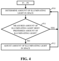
- FIG. 4 shows a flow chart of example processes for regulating illuminating light generated by a disinfecting light system within a space, according to embodiments of the disclosure.
- FIG. 5 shows a flow chart of example processes for regulating disinfecting energy generated by a disinfecting light system within a space, according to additional embodiments of the disclosure.
- FIG. 6 shows a schematic view of a disinfecting light system including a control system, according to embodiments of the disclosure.
- FIG. 7 shows a schematic view of a control system including a controller that regulates disinfecting energy generated by a disinfecting light system, according to embodiments of the disclosure.
- FIG. 8 shows a schematic view of an illustrative environment including a disinfecting light system and a control system, according to additional embodiments of the disclosure.
- FIG. 9 shows a schematic view of an illustrative environment including a disinfecting light system, a control system and a single sensor, according to embodiments of the disclosure.
- FIGS. 10 and 11 show schematic views of an illustrative environment including a disinfecting light system providing distinct amounts of disinfecting energy and/or illuminating light, according to embodiments of the disclosure.
- FIGS. 12 and 13 show schematic views of an illustrative environment including a disinfecting light system providing distinct amounts of disinfecting energy and/or illuminating light, according to additional embodiments of the disclosure.
- FIG. 14 shows a schematic view of an illustrative environment made up of a plurality of spaces in a single room of the environment, according to embodiments of the disclosure.
- the environment also includes a light system, a control system and a plurality of sensors.
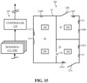
- FIG. 15 shows a schematic view of an illustrative environment made up of a plurality of spaces in two distinct rooms of the environment, according to embodiments of the disclosure.
- the environment also includes a light system, a control system and a plurality of sensors.
- the disclosure relates generally to illumination, and more particularly, to control systems for a disinfecting light emitting diode (LED) lighting system and methods of regulating operations of the disinfecting LED lighting systems.
- LED light emitting diode
- FIGS. 1 - 15 These and other embodiments are discussed below with reference to FIGS. 1 - 15 . However, those skilled in the art will readily appreciate that the detailed description given herein with respect to these Figures is for explanatory purposes only and should not be construed as limiting.
- FIG. 1 shows a schematic view of an illustrative environment including a disinfecting light system and a control system.
- FIG. 1 shows environment 10 and a disinfecting light system 100 that may be at least partially positioned within and/or may interact with environment 10 .
- environment 10 may be a room within a building.
- disinfecting light system 100 may illuminate environment 10 , as well as provide disinfecting energy within environment 10 in order to disinfect environment 10 .
- environment 10 may include a plurality of rooms and/or distinct areas that include disinfecting light system 100 .
- environment 10 may include at least one of the items and/or objects included therein.
- environment 10 may include a plurality of items and/or objects positioned within environment 10 .
- environment 10 formed as a room may include a window 12 formed in one of a plurality of walls 18 of environment.
- the window may provide an opening to environment 10 which may allow sunlight or natural light 20 to enter and/or be emitted into environment 10 .
- environment 10 may also include a door 22 to allow user(s) ( FIGS. 12 and 13 ) to access environment 10 and/or the items or objects positioned therein.
- environment 10 may also include a chair 24 , desk or workstation 26 (hereafter, “workstation 26 ”), and cabinets 28 .
- workstation 26 may be a “clean” or “sterile” workstation or area that may be used for specific, sterile procedures and/or processing (e.g., sterile table for microchip inspection).
- the items and/or objects e.g., window 12 , chair 24 , workstation 26 , and so on
- characteristics and/or properties of environment 10 may also be accounted for and/or may affect the regulation of operations of disinfecting light system 100 , and more specifically the regulation of the disinfecting energy and/or illuminating light provided to environment 10 , as discussed herein.
- the color of paint on walls 18 /door 22 may be accounted for and/or may affect the regulation of the disinfecting energy and/or illuminating light provided to environment 10 by disinfecting light system 100 .
- Environment 10 may include one or more spaces defined therein.
- environment 10 may include and/or be “divided” into a plurality of distinct spaces 30 , 32 .
- environment 10 e.g., room
- second space 32 may be included within first space 30 .
- second space 32 may be defined as distinct and/or unique from first space 30 by disinfecting light system 100 . That is, the spaces 30 , 32 of environment 10 may be based on and/or may be defined by, at least in part, disinfecting light system 100 of environment 10 and its various components (e.g., light fixtures), as discussed herein.
- the plurality of spaces 30 , 32 of environment 10 may be based on and/or may be defined by, at least in part, items and/or objects of environment 10 (e.g., sterile workstation 26 ), and/or characteristics and/or properties of environment 10 , as discussed herein (see, FIGS. 14 and 15 ).
- the number of spaces 30 , 32 shown in FIG. 1 and included within environment 10 are merely illustrative. As such, although two spaces 30 , 32 are shown and discussed herein, it is understood that environment 10 may include more or less spaces. In other non-limiting examples where environment 10 includes a plurality of rooms, spaces of environment 10 may be defined as each individual room making up environment 10 (see, FIG. 15 ). Additionally, or alternatively in the non-limiting examples, each of the plurality of rooms of environment may include one or more spaces similar to those discussed herein with respect to FIG. 1 (see, FIG. 14 ).
- Disinfecting light system 100 included and/or operating within environment 10 may include at least one disinfecting light fixture 102 , 104 .
- Disinfecting light fixture(s) 102 , 104 may be positioned within, exposed to, illuminate and/or may provide (light) energy to environment That is, and as discussed herein, disinfecting light fixture(s) 102 , 104 may be positioned within and/or exposed to environment 10 to provide illuminating light and/or disinfecting energy to environment 10 .
- a first disinfecting light fixture 102 may be positioned within environment 10 and may be coupled to a ceiling 34 of environment 10 .
- a second disinfecting light fixture 104 may be positioned within environment 10 and may be coupled to cabinets 28 , adjacent workstation 26 .
- the plurality of disinfecting light fixture(s) 102 , 104 within environment 10 may define, at least in part, space(s) 30 , 32 of environment 10 .
- the position of each of disinfecting light fixture(s) 102 , 104 within environment 10 and/or the area of environment in which the plurality of disinfecting light fixtures(s) 102 , 104 may illuminate and/or provide disinfecting energy may, at least in part, define space(s) 30 , 32 of environment 10 .
- First disinfecting light fixture 102 coupled to ceiling 34 of environment 10 may illuminate and/or provide disinfecting energy to substantially all of environment 10 (e.g., room). Therefore, the light emitted by first disinfecting light fixture 102 may define, at least in part, first space 30 . Additionally, second disinfecting light fixture 104 coupled to cabinet 28 of environment 10 may illuminate and/or provide disinfecting energy to workstation 26 . As such, the light emitted by second disinfecting light fixture 104 may define, at least in part, second space 32 .
- the plurality of disinfecting light fixture(s) 102 , 104 of disinfecting light system 100 may be any suitable light fixture, component, or assembly that is capable of providing a spectral range of light energy, illumination, and/or illuminating light, as well as, disinfecting energy to environment 10 .
- the plurality of disinfecting light fixture(s) 102 , 104 may be any suitable light fixture, component, or assembly that is capable of switching between providing only illuminating light, only disinfecting energy, or both illuminating light and disinfecting energy simultaneously.
- the plurality of disinfecting light fixture(s) 102 , 104 of disinfecting light system 100 may include light fixtures similar to those described in U.S. Pat. Nos. 9,333,274, 9,439,989, and U.S. Pat. Pub. No. 2017/0030555 the entirety of which is hereby incorporated herein by reference.
- the plurality of disinfecting light fixture(s) 102 , 104 of disinfecting light system 100 may also be any suitable light fixture, component, or assembly that is capable of adjusting and/or varying the brightness or lumen output of the illuminating light and/or the operational function, output, dosage, and/or intensity (hereafter, “operational intensity”) of the disinfecting energy during operation of disinfecting light fixture(s) 102 , 104 . That is, and as discussed herein, the plurality of disinfecting light fixture(s) 102 , 104 may be configured to and/or capable of adjusting the lumen output of the illuminating light and/or the operational intensity of the disinfecting energy provided to environment 10 .
- first disinfecting light fixture 102 may emit only light energy and/or illuminating light 106 (hereafter, “illuminating light 106 ”) to first space of environment 10 .
- second disinfecting light fixture 104 may emit both illuminating light 106 , as well as, disinfecting energy 108 to second space 32 of environment 10 .
- the output (e.g., illuminating light 106 , disinfecting energy 108 ) of each of the plurality of disinfecting light fixture(s) 102 , 104 may be based on sensed or measured characteristics of space(s) 30 , 32 of environment 10 , characteristics and/or properties of space(s) 30 , 32 of environment 10 , and/or predetermined information (e.g., scheduled outputs) for environment 10 .
- the number of disinfecting light fixture(s) 102 , 104 included within environment 10 is understood to be illustrative. As such, although disinfecting light system 100 is shown to include two disinfecting light fixture(s) 102 , 104 , it is understood that disinfecting light system 100 may include more or less disinfecting light fixture(s). Additionally, the position of disinfecting light fixture(s) 102 , 104 included within environment 10 , as shown in the non-limiting example of FIG. 1 , is understood to be illustrative.
- Disinfecting light fixture(s) 102 , 104 of disinfecting light system 100 may be positioned anywhere within, adjacent to, and/or exposed to environment 10 to provide illuminating light 106 and/or disinfecting energy 108 to a defined space within environment as discussed herein.
- illuminating light 106 may generate visible light energy within the spectral range of approximately 380 nanometers (nm) to approximately 750 nm, and disinfecting energy 108 may be a disinfecting energy within the spectral range of approximately 380 nm to approximately 420 nm (e.g., 405 nm). That is, illuminating light 106 may include visible light energy within a spectral range that may illuminate and/or provide light to space(s) 30 , 32 of environment 10 .
- disinfecting energy 108 generated by disinfecting light fixture(s) 102 , 104 may include disinfecting energy within the spectral range that may alter, adjust, and/or control the bacterial load, bioburden, and/or microbial load (e.g., disinfect, or sterilize) within space(s) 30 , 32 receiving disinfecting energy 108 (e.g., violet light).
- disinfecting energy 108 may include ultraviolent (UV) light having disinfecting properties and including a spectral range of approximately 100 nm to approximately 400 nm.
- UV ultraviolent
- illuminating light 106 and/or disinfecting energy 108 may be varied and/or adjusted.
- the plurality of disinfecting light fixture(s) 102 , 104 may be capable of varying and/or adjusting the lumen output of illuminating light 106 and/or the operational intensity of disinfecting light 108 during operation of disinfecting light fixture(s) 102 , 104 of disinfecting light system 100 .
- the lumen output of illuminating light 106 may be adjusted to increase or decrease the brightness of illuminating light 106
- the operational intensity of disinfecting energy 108 may be adjusted to increase or decrease the amount of disinfecting energy 108 provided to space(s) 30 , 32 .
- illuminating light 106 may be emitted within the spectral range of approximately 380 nm to approximately 750 nm, and disinfecting energy 108 may be emitted within the spectral range of approximately 380 nm to approximately 420 nm, or alternatively approximately 100 nm to approximately 420 nm. Additionally in a non-limiting example, the illuminating light 106 and/or disinfecting energy 108 may be adjusted and/or varied independent of the function and/or operation of one another.
- disinfecting light fixture(s) 102 , 104 may adjust the lumen output of the emitted illuminating light 106 when disinfecting light fixture(s) 102 , 104 is not emitting disinfecting energy 108 , or alternatively, without adjusting or varying the operational intensity of the emitted disinfecting energy 108 when disinfecting light fixture(s) 102 , 104 is emitting disinfecting energy 108 along with illuminating light 106 .
- disinfecting light fixture(s) 102 , 104 may adjust the operational intensity of the emitted disinfecting energy 108 when disinfecting light fixture(s) 102 , 104 is not emitting illuminating light 106 , or alternatively, without adjusting or varying the lumen output of the emitted illuminating light when disinfecting light fixture(s) 102 , 104 is emitting illuminating light 106 along with disinfecting energy 108 .
- the lumen output of illuminating light 106 and the operational intensity of disinfecting energy 108 may be adjusted and/or varied simultaneously.
- the lumen output of illuminating light 106 and the operational intensity of disinfecting energy 108 may be adjusted and/or varied independent of one another (e.g., increase in the lumen output of illuminating light 106 , decrease in the operational intensity of disinfecting energy 108 ).
- the lumen output of illuminating light 106 and the operational intensity of disinfecting energy 108 may be adjusted and/or varied based on sensed or measured characteristics of space(s) 30 , 32 of environment characteristics and/or properties of space(s) 30 , 32 of environment 10 , and/or predetermined information (e.g., scheduled outputs) for environment 10 .
- a quality of visible light generated by and/or provided to space(s) 30 , 32 by disinfecting light fixtures 102 , 104 may be affected.
- an output ratio may be between approximately 70-90% of illuminating light 106 and approximately 10-30% disinfecting energy 108 .
- a user of space(s) 30 , 32 may not detect any change in quality (e.g., color rendering) in illuminating light 106 based on the inclusion or emission of disinfecting energy 108 (e.g., violet light).
- disinfecting energy 108 e.g., violet light
- the quality of light provided to space(s) 30 , 32 by illuminating light 106 may be affected.
- the violet light may become more apparent and/or visible to a user of space(s) 30 , 32 , and/or certain colors forming illuminating light 106 may be come over or under saturated by violet light of disinfecting energy 108 .
- certain circumstances and/or situations for space(s) 30 , 32 may require more or less illuminating light 106 and/or disinfecting energy 108 , and may be performed or carried out within space(s) 30 , 32 with less disinfecting energy 108 and high light quality, or alternatively, may be performed with more disinfecting energy 108 and low light quality.
- disinfecting energy system 100 can include a control system 109 including at least one controller 110 configured to control operation of disinfecting light fixture(s) 102 , 104 . That is, controller 110 of control system 109 may be configured to regulate illuminating light 106 and disinfecting energy 108 (e.g., vary/adjust lumen output/operational intensity) provided to space(s) 30 , 32 of environment 10 via disinfecting light fixture(s) 102 , 104 . Controller 110 can be hard-wired and/or wirelessly connected to, operably coupled to, and/or in communication with disinfecting light fixture(s) 102 , 104 via any suitable electronic and/or mechanical communication component or technique. Controller 110 , and its various components discussed herein (see, FIG.
- controller 110 may be a single stand-alone system that functions separate from another system (e.g., computing device) (not shown) that may control and/or adjust operations or functions of other portions of environment (e.g., HVAC system).
- controller 110 may be integrally formed within, in communication with and/or formed as a part of a larger control system (e.g., computing device) (not shown) that may control and/or adjust operations or functions of environment 10 .
- controller 110 of control system 109 may be configured or formed as a microcontroller or similarly embedded system on a chip (SOC) component running a real-time operating system (RTOS).
- SOC system on a chip
- RTOS real-time operating system
- control system 109 for disinfecting light system 100 may also include one or more sensors 112 , 118 , 120 A, 120 B, 120 C, 122 , 124 operably coupled to and/or in communication with controller 110 for aiding controller 110 in controlling the operation of disinfecting light fixture(s) 102 , 104 .
- controller 110 may utilize data, real-time information, and/or environment characteristics of space(s) 30 , 32 of environment 10 , as determined by sensor(s) 112 , 118 , 120 A, 120 B, 120 C, 122 , 124 , to control the operation of disinfecting light fixture(s) 102 , 104 to ultimately regulate illuminating light 106 and disinfecting energy 108 provided to space(s) 30 , 32 of environment 10 .
- controller 110 of control system 109 may be operably coupled to, in electrical and/or mechanical communication with sensor(s) 112 , 118 , 120 A, 120 B, 120 C, 122 , 124 positioned throughout environment 10 (e.g., one shown). Additionally, and as shown in the non-limiting example of FIG. 1 , controller 110 may be wirelessly connected to, and/or in communication with sensor(s) 112 , 118 , 120 A, 120 B, 120 C, 122 , 124 . Sensor(s) 112 , 118 , 120 A, 120 B, 120 C, 122 , 124 may be positioned in various locations and/or throughout environment 10 , and more specifically space(s) 30 , 32 .
- the position and/or location of sensor(s) 112 , 118 , 120 A, 120 B, 120 C, 122 , 124 within space(s) 30 , 32 of environment 10 may be dependent, at least in part, on the type of sensor, and/or the data, information, and/or characteristic of space(s) 30 , 32 the sensor is measuring, detecting, and/or sensing.
- Sensor(s) 112 , 118 , 120 A, 120 B, 120 C, 122 , 124 in communication with controller 110 of control system 109 may be any suitable sensor or device configured to detect and/or determine data, information, and/or characteristics relating to environment 10 .
- sensor(s) 112 , 118 , 120 A, 120 B, 120 C, 122 , 124 positioned within space(s) 32 may be any suitable sensor configured to detect, measure, sense, and/or determine an amount of disinfecting energy 108 provided to space(s) 30 , 32 by disinfecting light fixture(s) 102 , 104 , a bacterial load for space(s) 30 , 32 , and/or environmental characteristics (e.g., occupancy, daylight) for space(s) 30 , 32 .
- environmental characteristics e.g., occupancy, daylight
- environment 10 may include a first sensor 112 .
- first space 30 of environment 10 may include first sensor 112 positioned therein and in (wireless) communication with and/or operably connected to controller 110 of control system 109 .
- first sensor 112 may be positioned on and/or coupled to ceiling 34 within first space 30 .
- First sensor 112 may be configured as any suitable sensor capable of measuring an amount of disinfecting energy 108 provided to space 30 by first disinfecting light fixture 102 of disinfecting light system 100 .
- first sensor 112 of disinfecting light system 100 may include or be formed as a spectrometer, a photodiode, a watt meter, or any other suitable sensor that may be capable of measuring and/or detecting the amount of disinfecting energy 108 provided to first space 30 by first disinfecting light fixture 102 .
- the amount of disinfecting energy 108 provided to first space 30 by first disinfecting light fixture 102 may be provided or transmitted to controller 110 to aid in controller's regulation of disinfecting energy 108 generated by first disinfecting light fixture 102 of disinfecting light system 100 .
- controller 110 may compare the measured amount of disinfecting energy 108 provided to first space 30 by first disinfecting light fixture 102 to a disinfecting energy threshold, and may adjust the amount of disinfecting energy 108 provided to space 30 by adjusting the output of first disinfecting light fixture 102 .
- first sensor 112 may be positioned anywhere within first space 30 so long as first sensor 112 is capable of measuring the amount of disinfecting energy 108 provided to first space 30 by first disinfecting light fixture 102 .
- environment 10 may also include a second sensor 118 .
- first space 30 of environment 10 may include second sensor 118 positioned therein and in (wireless) communication with and/or operably connected to controller 110 of control system 109 .
- second sensor 118 may be positioned on and/or coupled to wall 18 within first space 30 .
- Second sensor 118 may be configured as any suitable sensor capable of sensing a bacterial load of space 30 . More specifically, second sensor 118 may be any suitable sensor capable of sensing bacterial load, bioburden, and/or microbial load within space 30 of environment 10 .
- second sensor 118 of disinfecting light system 100 may include or be formed as an optical sensor, oxygen-depletion sensor, luminometer, or any other suitable sensor that may be capable of sensing a bacterial load within first space 30 .
- second sensor 118 may sense the bacterial load of first space 30 by measuring the bacterial load of the air within first space 30 , and/or measuring the bacterial load on a surface of an object or item (e.g., window 12 , wall 20 , door 22 , chair 24 , and so on) positioned within first space 30 .
- an object or item e.g., window 12 , wall 20 , door 22 , chair 24 , and so on
- the bacterial load of first space 30 may be based on a correlated measurement.
- the correlated measurement may be a calculated or determined bacterial load based on collected data that may be correlated to a bacterial load measurement. That is, data collected, measured, determined, and/or sensed by second sensor 118 may be provided to controller 110 , which in turn may process and/or utilize the data from second sensor 118 to calculate or determined the bacterial load forming the correlated measurement.
- the data collected by second sensor 118 may not be data including and/or pertaining directly to bacteria, microbial, and/or bioburden data, but rather may be data that can be utilized to calculate or determined the bacterial load, as discussed herein.
- the bacterial load of first space 30 may change based on changes within first space 30 .
- the bacterial load of first space 30 may increase as a result of increased room occupancy by users, when new items or objects are introduced to first space 30 of environment and/or over a period of time where first disinfecting light fixture 102 is not providing disinfecting energy 108 to first space 30 .
- the bacterial load of space 30 sensed by second sensor 118 , may be provided or transmitted to controller 110 to aid in controller's regulation of disinfecting energy 108 generated by first disinfecting light fixture 102 of disinfecting light system 100 .
- controller 110 may compare the sensed bacterial load of first space 30 to a bacterial load threshold, and may adjust the amount of disinfecting energy 108 provided to space 30 by adjusting the output of first disinfecting light fixture 102 . That is, the bacterial load sensed by second sensor 118 within first space 30 may be directly affected and/or impacted by the amount of disinfecting energy 108 provided to space by first disinfecting light fixture 102 . Although shown as being coupled to wall 18 within space 30 of environment 10 , it is understood that second sensor 118 may be positioned anywhere within space 30 so long as second sensor 118 is capable of sensing the bacterial load of first space 30 .
- First space 30 of environment 10 may also include at least one additional, third sensor 120 A, 120 B, 120 C positioned therein and in (wireless) communication with and/or operably connected to controller 110 of control system 109 .
- control system 109 may include a plurality of third sensors 120 A, 120 B, 120 C positioned throughout first space 30 of environment 10 .
- Each of the plurality of third sensors 120 A, 120 B, 120 C may be configured as environmental characteristic sensors, and/or may be sensors configured to measure or detect environmental characteristics of first space 30 of environment 10 .
- a preferred amount of disinfecting energy for and/or to be provided to first space 30 may be associated with the environmental characteristics detected by third sensors 120 A, 120 B, 120 C within first space 30 .
- controller 110 may compare the measured amount of disinfecting energy 108 within first space 30 (e.g., first sensor) with the preferred amount of disinfecting energy associated with detected environmental characteristics of first space 30 , and may adjust the amount of disinfecting energy 108 provided to space 30 by adjusting the output of first disinfecting light fixture 102 .
- each of the environmental characteristics detected by third sensors 120 A, 120 B, 120 C may include a preferred amount or level of illuminating light that may be associated with the detected environmental characteristic(s). That is, a preferred amount of illuminating light for and/or to be provided to first space 30 may be associated with the environmental characteristics detected by third sensors 120 A, 120 B, 120 C within first space Additionally, controller 110 may compare a measured amount of illuminating light 106 provided to first space 30 (e.g., third sensor, disinfecting light fixture) with the preferred amount of illuminating light associated with detected environmental characteristics of first space 30 , and may adjust the amount of illuminating light 106 provided to space 30 by adjusting the output of first disinfecting light fixture 102 .
- first space 30 e.g., third sensor, disinfecting light fixture
- the plurality of third sensors 120 A, 120 B, 120 C configured to detect environmental characteristics of first space 30 may all be the distinct types of sensors and/or may detect distinct environmental characteristics of first space 30 .
- the plurality of third sensors 120 A, 120 B, 120 C may all be the same type of sensor and/or may detect the same environmental characteristics of first space 30 .
- Third sensor 120 A may be positioned on and/or coupled to a wall 36 within first space 30 . Additionally, third sensor 120 A may be coupled to wall 36 , above cabinet 28 included within first space 30 . Third sensor 120 A may be configured as any suitable sensor capable of measuring or detecting an occupancy level (e.g., environmental characteristic) for first space 30 .
- the detected occupancy level for first space 30 may include whether or not first space 30 is being occupied and/or includes a user(s) positioned therein, the number of users that may occupy first space 30 and/or a (real-time) change in occupancy for first space 30 .
- third sensor 120 A of control system 109 may include or be formed as an infrared sensor, an automated camera system (e.g., image processing with camera based sensors), radar sensor, Lidar sensor, audio sensor, (tomographic) motion sensor, microwave sensor, ultrasonic sensor, or any other suitable sensor that may be capable of detecting an occupancy level of first space 30 .
- the occupancy level of first space 30 may be provided or transmitted to controller 110 to aid in controller's regulation of disinfecting energy 108 generated by first disinfecting light fixture 102 of disinfecting light system 100 .
- controller 110 may receive the occupancy level of first space 30 from third sensor 120 A, along with a preferred amount of disinfecting energy associated with the occupancy level of first space 30 . Additionally, controller 110 may compare the measured amount of disinfecting energy 108 of first space 30 (e.g., first sensor 112 ) with the preferred amount of disinfecting energy associated with the occupancy level of first space 30 detected by third sensor 120 A, and may adjust the amount of disinfecting energy 108 provided to space 30 by adjusting the output of first disinfecting light fixture 102 .
- controller 110 may adjust the amount of illuminating light 106 provided to space 30 by adjusting the output of first disinfecting light fixture 102 based on the preferred amount of illuminating light that may be associated with the detected, occupancy level of first space 30 .
- third sensor 120 A may be positioned anywhere within first space 30 so long as third sensor 120 A is capable of detecting the occupancy level of first space 30 .
- Third sensor 120 B may be positioned on and/or coupled to floor 38 of environment 10 . Specifically, third sensor 120 B may be coupled to floor 38 with first space 30 , substantially adjacent, aligned with, below and/or within proximity of window 12 included within first space 30 of environment 10 . Additionally, as shown in FIG. 1 , third sensor 120 B may be positioned substantially below, aligned with, and/or within proximity of first disinfecting light fixture 102 of disinfecting light system 100 . Third sensor 120 B may be configured as any suitable sensor capable of detecting an amount of visible light (e.g., illuminating light 106 , natural light) in first space 30 .
- visible light e.g., illuminating light 106 , natural light
- third sensor 120 B of control system 109 may include or be formed as a spectrometer, a photodiode, a watt meter, or any other suitable sensor that may be capable of sensing an amount of visible light (e.g., illuminating light 106 , natural light) within first space 30 .
- third sensor 120 B may be configured as a daylight sensor that may sense an amount of natural light 20 included within first space 30 .
- the amount of natural light of first space 30 may be provided or transmitted to controller 110 to aid in controller's regulation of disinfecting energy 108 generated by first disinfecting light fixture 102 of disinfecting light system 100 .
- controller 110 may receive the amount of natural light 20 of first space 30 from third sensor 120 B, along with a preferred amount of disinfecting energy associated with the detected amount of natural light 20 of first space 30 .
- controller 110 may compare the measured amount of disinfecting energy 108 of first space 30 (e.g., first sensor 112 ) with the preferred amount of disinfecting energy associated with the amount of natural light 20 of first space 30 detected by third sensor 120 B, and may adjust the amount of disinfecting energy 108 provided to space by adjusting the output of first disinfecting light fixture 102 .
- the amount of natural light 20 sensed by third sensor 120 B may also include a known, calculated, predetermined, and/or measurable amount of natural disinfecting energy (e.g., spectral energy of approximately 405 nm), which may be provided to first space 30 .
- third sensor 120 B of control system 109 may be configured to measure an amount of natural disinfecting energy 40 provided to first space 30 along with natural light 20 .
- the amount of natural disinfecting energy from natural light 20 may be calculated or determined based on a variety of factors including, but not limited to, the time of day, the date, the position of first space 30 and/or window 12 (e.g., facing east), and characteristics of window 12 (e.g., double-pane, blue light blocker, tinted, and so on).
- controller 110 of control system 109 may receive the measured amount of natural disinfecting energy 40 , or determine the amount of natural disinfecting energy 40 , provided to first space 30 via natural light 20 sensed by third sensor 120 B, and may adjust the amount of disinfecting energy 108 provided to space 30 by adjusting the output of first disinfecting light fixture 102 .
- third sensor 120 B may be configured as a visible light sensor that may sense the amount of illuminating light 106 provided to first space 30 by first disinfecting light fixture 102 .
- the amount of illuminating light 106 provided to first space 30 by first disinfecting light fixture 102 , and sensed by third sensor 120 B, may be provided or transmitted to controller 110 to aid in the controller's regulation of illuminating light 106 generated by first disinfecting light fixture 102 .
- controller 110 may receive the amount of illuminating light 106 of first space 30 from third sensor 120 B, along with a preferred amount of illuminating light associated with first space 30 .
- the preferred amount of illuminating light may be based on sensed or measured characteristics of first space 30 (e.g., occupancy level, amount of natural light 20 , task(s), and so on), characteristics and/or properties of first space 30 , and/or predetermined information (e.g., scheduled outputs) for first space 30 . Additionally, controller 110 may compare the measured amount of illuminating light 106 of first space 30 with the preferred amount of illuminating light for first space 30 , and may adjust the amount of illuminating light 106 provided to first space 30 by adjusting the output of first disinfecting light fixture 102 .
- third sensor 120 B may be configured as a visible light sensor that may sense a total amount of visible light (e.g., combination or sum of illuminating light 106 and natural light 20 ) within first space 30 , as well as sense natural light 20 provided to first space 30 , as discussed herein.
- third sensor 120 B may provide the total amount of visible light and natural light 20 provided to first space 30 , and sensed by third sensor 120 B, to controller 110 .
- controller 110 may analyze and/or compare the total amount of visible light and natural light 20 provided to first space 30 to determine the amount of illuminating light 106 provided to first space 30 by first disinfecting light fixture 102 .
- Controller 110 may then compare the determined amount of illuminating light 106 of first space 30 with a preferred amount of illuminating light for first space 30 , and may adjust the amount of illuminating light 106 provided to first space 30 by adjusting the output of first disinfecting light fixture 102 .
- third sensor 120 B may be positioned anywhere within first space 30 so long as third sensor 120 B is capable of sensing the amount of natural light 20 for first space 30 .
- third sensor 120 C of control system 109 may be positioned within first space 30 of environment 10 .
- third sensor 120 C may be coupled to door 22 within first space 30 .
- Third sensor 120 C may be configured as any suitable sensor capable of identifying at least one task being carried out in first space 30 . That is, third sensor 120 C may be a task-identifying sensor that may detect, sense, and/or identify task(s) being carried out and/or performed within first space 30 of environment 10 .
- the identified task being carried out and/or performed within the first space 30 may require a predetermined or preferred amount of illuminating light 106 and/or disinfecting energy 108 to be provided to first space 30 by first disinfecting light fixture 102 when performing the task.
- third sensor 120 C of control system 109 may include or be formed as a camera sensor (e.g., image processing with camera based sensors) and/or a scanner sensor that may detect certain work pieces and/or users associated with a predetermined task are positioned or located within first space 30 . Additionally in another non-limiting, third sensor 120 C may be formed as a component-detection sensor, which may be configured to identify when an object, and/or item (e.g., microscope (not shown)) of first space 30 that is associated with and/or used specifically for a certain task is being utilized within first space 30 .
- a camera sensor e.g., image processing with camera based sensors
- scanner sensor e.g., a scanner sensor that may detect certain work pieces and/or users associated with a predetermined task are positioned or located within first space 30 .
- third sensor 120 C may be formed as a component-detection sensor, which may be configured to identify when an object, and/or item (e.g., microscope (not shown)) of
- Controller 110 may identify that a task(s) is being carried out in first space 30 , via third sensor 120 C, and may adjust the amount of disinfecting energy 108 provided to space 30 by adjusting the output of first disinfecting light fixture 102 . That is, controller 110 may receive the task(s) being carried out in first space 30 , as identified by third sensor 120 C, along with a preferred amount of disinfecting energy associated with the identified task being carried out in first space 30 .
- controller 110 may compare the measured amount of disinfecting energy 108 of first space 30 (e.g., first sensor 112 ) with the preferred amount of disinfecting energy associated with the identified task(s) of first space 30 , identified by third sensor 120 C, and may adjust the amount of disinfecting energy 108 to space 30 by adjusting the output by first disinfecting light fixture 102 .
- controller 110 may adjust the amount of illuminating light 106 provided to space 30 by adjusting the output of first disinfecting light fixture 102 based on the preferred amount of illuminating light that may be associated with the detected, task(s) being carried out in first space 30 . That is, a preferred amount of illuminating light for and/or to be provided to first space 30 may be associated with the task(s) to be performed in first space 30 , and detected by third sensor 102 C.
- controller 110 may compare a measured amount of illuminating light 106 provided to first space 30 (e.g., third sensor 120 B, disinfecting light fixture) with the preferred amount of illuminating light associated with the detected task(s) for first space 30 , and may adjust the amount of illuminating light 106 provided to space 30 by adjusting the output of first disinfecting light fixture 102 .
- third sensor 120 C may be positioned anywhere within first space 30 so long as third sensor 120 C is capable of that a task(s) is being carried out within first space 30 .
- control system 109 of disinfecting light system 100 is shown to include five sensors 112 , 118 , 120 A, 120 B, 120 C within first space 30 , it is understood that control system 109 may include more or less sensors for providing data and/or information to controller 110 (see, FIGS. 8 - 13 ).
- first space 30 is shown to include five sensors 112 , 118 , 120 A, 120 B, 120 C, it is understood that controller 110 may adjust the amount of illuminating light 106 and/or disinfecting energy 108 provided to space 30 by adjusting the output of first disinfecting light fixture 102 based on only a portion of the five sensors 112 , 118 , 120 A, 120 B, 120 C.
- control system 109 may include first sensor 112 and one or more third sensors 120 A, 120 B, 120 C.
- control system 109 may include first sensor 112 and second sensor 118 .
- control system 109 may include second sensor 118 and one or more third sensors 120 A, 120 B, 120 C.
- control system 109 may utilize additional components to aid in the measuring, sensing, and/or detected of characteristics relating to space(s) 30 , 32 , as discussed herein. For example, and as discussed in detail herein with respect to FIG.
- third sensor 120 A configured to detect an occupancy level of space(s) 30 , 32 of environment 10 may be configured as a video surveillance system that may monitor activity within space(s) 30 , 32 , and may be utilized to provide data to third sensor 120 A regarding the occupancy level, which in turn may be provided to controller 110 of control system 109 , as similarly discussed herein.
- sensors 112 , 118 , 120 A, 120 B, 120 C providing or transmitting data and/or information relating to disinfecting light system 100 and/or space(s) 32 to controller 110
- some of the data may be provided from distinct components within disinfecting light system 100 .
- data and/or information relating to an amount of illuminating light 106 and/or disinfecting energy 108 provided to first space 30 by first disinfecting light fixture 102 may be provided to controller 110 by first disinfecting light fixture 102 of disinfecting light system 100 .
- control system 109 of disinfecting light system 100 may also include at least one access control component 126 .
- access control component 126 may be positioned within first space 30 of environment 10 .
- access control component 126 may be positioned on wall 42 , adjacent door 22 , within first space 30 .
- Access control component 126 may be operably coupled to and/or in communication with controller 110 for providing data, information, and/or input to controller for controlling the operation of disinfecting light fixture(s) 102 and more specifically, regulating illuminating light 106 and disinfecting energy 108 provided to first space 30 of environment 10 .
- access control component 126 may provide an override selector or option that may be configured to temporarily permit switching controller 110 off and/or suspending the operational processes performed by controller 110 of control system 109 .
- a user(s) may utilize access control component 126 to manually adjust the operation of controller 110 for controlling illuminating light 106 and/or disinfecting energy 108 provided to first space 30 by first disinfecting light fixture 102 , independent of the data provided to controller 110 by sensors 112 , 118 , 120 A, 120 B, 120 C.
- first disinfecting light fixture 102 maintaining a continuous disinfecting energy 108 within first space 30 , or alternatively, maintaining an average disinfection level or amount of disinfecting energy 108 in first space 30 at a minimum level.
- the continuous disinfecting energy 108 or average disinfection level of disinfecting energy 108 may be maintained despite changes in first space objects or items (e.g., moving chair 24 ), changes in first space 30 characteristics (e.g., changing wall 18 paint reflectivity, opening/closing curtains on window 12 ), and/or detected and/or sensed data (e.g., change in bacterial load sensed by second sensor 118 , occupancy level detected by third sensor 120 A).
- access control component 126 may provide a user(s) located in first space 30 the option to manually input a predetermined task to be carried out within first space 30 .
- third sensor 120 C may not be included within first space 30 , or alternatively, third sensor 120 C may not be able to detect the task to be carried out in first space 30 due to circumstances surrounding the task; for example, a workpiece for the task is not yet within first space 30 , or first space 30 needs to have a detected amount of disinfecting energy 108 before a workpiece is brought into first space 30 for the task.
- controller 110 for controlling illuminating light 106 and/or disinfecting energy 108 provided to first space 30 by disinfecting light system 102 may be adjusted independent of the data provided to controller 110 by third sensors 120 C. That is, user(s) may manually adjust illuminating light 106 and/or disinfecting energy 108 using access control component 126 , based on a detected or identified task(s) to be performed with first space 30 , independent of the data obtained, sensed, measured, and/or detected by the sensors 112 , 118 , 120 A, 120 B, 120 C of control system 109 , as discussed herein.
- access control component 126 may include a security access system to allow users access to first space 30 of environment 10 .
- a code associated with a user(s) such as an input code or keycard, may be input, detected, and/or registered with access control component 126 , and may provide information, data and/or input from access control component 126 to controller 110 relating to first space 30 .
- access control component 126 may provide information or data relating to an occupancy level of first space 30 based on the user's accessing first space 30 to controller 110 .
- user(s) may be associated with a specific task to be performed within first space 30 .
- the specific task associated with the user to be performed in the first space may require a predetermined amount of illuminating light 106 and/or disinfecting energy 108 to be provided to first space 30 by first disinfecting light fixture 102 when performing the task.
- access control component 126 may provide the user information and/or data to controller 110 , which may include the specific task associated with the user, and controller 110 may adjust illuminating light 106 and/or disinfecting energy 108 accordingly, as discussed herein.
- access control component 126 may include and/or be formed as an operational schedule system for first space 30 of environment 10 . More specifically, access control component 126 may include and/or be formed as an operational schedule system and/or a system capable of providing a predetermined, operational schedule to controller 110 for controlling the operation of first disinfecting light fixture 102 and/or adjusting illuminating light 106 and/or disinfecting energy 108 provided to first space 30 by first disinfecting light fixture 102 .
- the predetermined, operational schedule provided to controller 110 from access control component 126 may be defined or created by a user(s) and/or operator of disinfecting light system 100 (e.g., building owner or maintenance person for the building include the room forming environment 10 ).
- the predetermined operational schedule which determines how controller 110 adjusts illuminating light 106 and/or disinfecting energy 108 to be provided to first space 30 , may be based on a plurality of data, factors, information, and/or operational scenarios surrounding the operation of disinfecting light system 100 .
- the predetermined operational schedule provided to controller 110 may be defined and/or created based on schedule data which includes a time of day and/or a day in a week. That is, controller 110 may adjust illuminating light 106 and/or disinfecting energy 108 provided to first space 30 by first disinfecting light fixture 102 based on the time of day (e.g., day vs. night), and/or the day in the week (e.g., weekday vs. weekend).
- the schedule data, information, and/or operational scenarios for the predetermined operational scheduled may also include associated, scheduled amounts of disinfecting energy to be provided to first space 30 .
- the scheduled amounts of disinfecting energy to be provided to first space 30 may include, for example, a minimum operational dosage or output of disinfecting energy 108 to be provided to first space 30 , and/or an average amount of disinfecting energy 108 (e.g., daily joule dosage, 6 joules per day) to be maintained over a predetermined period of time.
- the output of illuminating light 106 may be minimal when compared to a total or combined amount of output (e.g., illuminating light 106 and disinfecting energy 108 ) from first disinfecting light fixture 102 .
- controller 110 may control first disinfecting light fixture 102 such that first disinfecting light fixture 102 emits a maximum operational dosage and/or output (e.g., 100% intensity) or a high operational intensity (e.g., between approximately 75% to approximately 90% intensity) disinfecting energy 108 (e.g., scheduled amount of disinfecting energy).
- controller 110 may control first disinfecting light fixture 102 such that first disinfecting light fixture 102 emits a smaller, predetermined operational intensity (e.g., between approximately 10% to approximately 40% intensity) of disinfecting energy 108 .
- controller 110 may control first disinfecting light fixture 102 such that output from first disinfecting light fixture 102 is made up and/or includes the remaining percentage of disinfecting energy 108 .
- controller 110 may adjust illuminating light 106 and/or disinfecting energy 108 based on the predetermined operational schedule provided by access control component 126 to maintain appropriate illuminating light 106 when first space 30 is in use, and maintain a minimum dosage of disinfecting energy 108 with first space 30 (e.g., at night when first space 30 is not being used) (e.g., scheduled amount of disinfecting energy).
- an average amount of disinfecting energy 108 (e.g., daily joule dosage, 6 joules per day) can be maintained over a predetermined period of time while also maintaining illuminating light 106 as needed for use of first space 30 (e.g., scheduled amount of disinfecting energy).
- controller 110 may control first disinfecting light fixture 102 during evening hours such that first disinfecting light fixture 102 emits a predetermined amount of disinfecting energy 108 at a specific intensity during the evening hours to maintain a minimum dosage of disinfecting energy 108 in first space 30 .
- controller 110 may control first disinfecting light fixture 102 to emit disinfecting energy 108 at a minimum of 10% operational dosage intensity during the evening hours. Additionally, or alternatively, controller 110 may control first disinfecting light fixture 102 during evening hours such that first disinfecting light fixture 102 emits a predetermined amount disinfecting energy 108 at a specific or determined intensity during the evening hours to maintain an amount of disinfecting energy 108 over the predetermined amount of time. For example, the amount of disinfecting energy 108 over the predetermined amount of time is 6 joules per day. Additionally in the example, it may be determined that during 18-usage hours for first space 30 , first disinfecting light fixture 102 may emit disinfecting energy 108 at a 10% intensity to generate 3 joules of energy.
- controller 110 may control first disinfecting light fixture 102 to emit disinfecting energy 108 at a determined intensity over the next or remaining 6 hours to meet the amount of disinfecting energy 108 over the predetermined amount of time. That is, controller 110 may control first disinfecting light fixture 102 to adjust the disinfecting energy 108 , and specifically the intensity of disinfecting energy 108 emitted to first space 30 , over the remaining 6 hours to ensure first space 30 receives 6 joules of energy within the day (e.g., amount of disinfecting energy 108 over the predetermined amount of time).
- controller 110 may adjust the intensity of disinfecting energy 108 to approximately 30% operational intensity during the remaining 6 hours of the day to ensure first space 30 receives 6 joules of energy within a day.
- controller 110 may also stagger the intensity to account for potential or possible interruptions to the first space 30 and/or first disinfecting light fixture 102 . That is, in another non-limiting example, controller 110 may control or adjust the operation of first disinfecting light fixture 102 to meet the amount of disinfecting energy 108 over the predetermined amount of time before the predetermined amount of time has expired or past.
- the amount of disinfecting energy 108 over the predetermined amount of time is 6 joules per day, and it may be determined that during 18-usage hours for first space 30 , first disinfecting light fixture 102 may emit disinfecting energy 108 at a 10% intensity to generate 3 joules of energy. Rather than providing the remaining disinfecting energy 108 at a determined intensity over the remaining 6 hours (e.g., 30% intensity over 6 hours) to meet the amount of disinfecting energy 108 over the predetermined amount of time, controller 110 may control or adjust the operation of first disinfecting light fixture 102 over a shorter period of time.
- controller 110 may adjust the intensity of disinfecting energy 108 to approximately 60% operational intensity during 3 hours of the remaining 6 hours of the day to ensure first space 30 receives 6 joules of energy within a day.
- controller 110 may adjust or control the operation of first disinfecting light fixture 102 such that first disinfecting light fixture 102 emits disinfecting energy 108 at approximately 60% operational intensity for 3 hours, and approximately 0% operational intensity (e.g., no emitted disinfecting energy 108 ) for the distinct 3 hours.
- Adjusting the operation of first disinfecting light fixture 102 in this manner may provide a fail-safe for meeting the amount of disinfecting energy 108 over the predetermined amount of time, and/or may compensate for unscheduled or unplanned interruptions to first space 30 which may require a change in the operation of first disinfecting light fixture 102 (e.g., janitor enters the room, unscheduled/emergency maintenance during evening hours). Additionally, and as discussed herein, controller 110 may learn, adapt, and/or adjust data relating to first space 30 . As a result, and in the non-limiting example discussed herein, controller 110 may anticipate and/or determine a probability or likeliness that first space 30 may experience an unscheduled or unplanned interruption over time.
- controller 110 may be beneficial for controller 110 to utilize the learned or anticipated information relating to the probability or likeliness that first space 30 may experience an unscheduled or unplanned interruption, and control the operation of first disinfecting light fixture 102 in the fail-safe manner discussed herein to meet the amount of disinfecting energy 108 over the predetermined amount of time.
- the predetermined operational schedule provided to controller 110 may be defined and/or created based on schedule data that includes the cost of electricity for operating first disinfecting light fixture 102 .
- controller 110 may adjust illuminating light 106 and/or disinfecting energy 108 provided to first space 30 by first disinfecting light fixture 102 based on when electricity consumption for operating first disinfecting light fixture is at its highest (e.g., peak hours) and its lowest (e.g., off-peak hours).
- Controller 110 may control operation and/or adjust first disinfecting light fixture 102 to operate (e.g., provide disinfecting energy 108 ) at minimal power consumption when the electricity costs the most (e.g., peak hours), followed by increased operation (e.g., disinfecting energy 108 ) when electricity costs the least (e.g., off-peak hours), to maintain an average amount of disinfecting energy 108 (e.g., daily joule dosage) within free space 30 .
- first disinfecting light fixture 102 may consume, and/or require more energy to provide disinfecting energy 108 than illuminating light 106 . As such, and especially during peak hours, it may be more costly to provide disinfecting energy 108 to first space 30 than illuminating light 106 .
- control 110 may control operation and/or adjust first disinfecting light fixture 102 to provide the majority of disinfecting energy 108 during off-peak hours.
- evening hours e.g., 10:00 PM to 4:00 AM
- control 110 may control first disinfecting light fixture 102 to provide the majority of disinfecting energy 108 during evening hours to not only meet and/or maintain a minimum dosage of disinfecting energy 108 in first space 30 , but also to meet and/or maintain an average amount of disinfecting energy 108 over the predetermined amount of time. This in turn may regulate disinfecting energy 108 provided to space 30 , while also reducing the cost for operating disinfecting light system 100 , as discussed herein.
- controller 110 of control system 109 may adjust the operation of first disinfecting light fixture 102 based on a variety or plurality of data and/or information.
- controller 110 may receive and process the measured amount of disinfecting energy 108 from first sensor 112 and a corresponding disinfecting energy threshold, and the bacterial load for first space 30 sensed by second sensor 118 and a corresponding bacterial load threshold.
- controller 110 may receive and process environmental characteristic(s) (e.g., occupancy level, visible light, task(s), and so on) detected by third sensors 120 A, 120 B, 120 C and a corresponding preferred amount of disinfecting energy for each of the detected environmental characteristic(s). Furthermore, controller 110 may receive and process schedule data and scheduled amount of disinfecting energy associated with the schedule data from access control component 126 . Once controller 110 receives the data and/or information from a plurality of sensors 112 , 118 , 120 A, 120 B, 120 C and/or access control component 126 , controller 110 may analyze, and/or prioritize all of the data and/or information prior to adjusting the operation of first disinfecting light fixture 102 , as discussed herein.
- environmental characteristic(s) e.g., occupancy level, visible light, task(s), and so on
- controller 110 may prioritize the data and/or information based on the type of data and/or information received and/or the type of sensors 112 , 118 , 120 A, 120 B, 120 C, and/or access control component 126 included within first space 30 , and then may compare the prioritized data. For example, controller 110 may prioritize the sensed bacterial load and corresponding bacterial load threshold (e.g., second sensor 118 ) over or above the measured amount of disinfecting energy and disinfecting energy threshold (e.g., first sensor 112 ), environmental characteristic(s) and corresponding preferred amount of disinfecting energy (e.g., third sensors 120 A, 120 B, 120 C), and/or schedule data and the scheduled amount of disinfecting energy (e.g., access control component 126 ).
- the sensed bacterial load and corresponding bacterial load threshold e.g., second sensor 118
- the measured amount of disinfecting energy and disinfecting energy threshold e.g., first sensor 112
- environmental characteristic(s) and corresponding preferred amount of disinfecting energy e.
- controller 110 may adjust the operation of, and more specifically the amount of disinfecting energy 108 emitted by, first disinfecting light fixture 102 based solely on the sensed bacterial load and the bacterial load threshold, as discussed herein.
- controller 110 may compare the data and/or information.
- the prioritized bacterial load threshold and specifically the predetermined, preferred, or required disinfecting energy associated with the bacterial load threshold (e.g., second sensor 118 ) may be compared to the disinfecting energy threshold (e.g., first sensor 112 ), the preferred amount of disinfecting energy associated with the environmental characteristic(s) (e.g., third sensor 120 A, 120 B, 120 C), and/or the scheduled amount of disinfecting energy associated with the schedule data (e.g., access control component 126 ).
- controller 110 may determine how to adjust the operation, and more specifically adjust disinfecting energy 108 , of first disinfecting light fixture 102 .
- the predetermined, preferred, or required disinfecting energy associated with the prioritized bacterial load threshold may be greater than the disinfecting energy threshold, the preferred amount of disinfecting energy associated with the environmental characteristic(s), and/or the scheduled amount of disinfecting energy associated with the schedule data.
- controller 110 may adjust disinfecting energy 108 provided to first space 30 by first disinfecting light fixture 102 to equal and/or meet the predetermined, preferred, or required disinfecting energy associated with the prioritized bacterial load threshold.
- disinfecting energy 108 emitted by first disinfecting light fixture 102 By adjusting disinfecting energy 108 emitted by first disinfecting light fixture 102 to equal and/or meet the predetermined, preferred, or required disinfecting energy associated with the prioritized bacterial load threshold, which may be greater than the remaining disinfecting energies associated with the received data and/or information, it may ensure that the other disinfecting energy 108 requirements are also met.
- the predetermined, preferred, or required disinfecting energy associated with the prioritized bacterial load threshold may be less than the disinfecting energy threshold, the preferred amount of disinfecting energy associated with the environmental characteristic(s), and/or the scheduled amount of disinfecting energy associated with the schedule data.
- controller 110 may adjust disinfecting energy 108 provided to first space 30 by first disinfecting light fixture 102 to equal and/or meet the predetermined, preferred, or required disinfecting energy associated with the prioritized bacterial load threshold regardless of the other, greater disinfecting energies associated with the received data and/or information.
- controller 110 may adjust disinfecting energy 108 provided to first space 30 by first disinfecting light fixture 102 to equal and/or meet the disinfecting energy threshold, the preferred amount of disinfecting energy associated with the environmental characteristic(s), and/or the scheduled amount of disinfecting energy associated with the schedule data, rather than the disinfecting energy associated with the prioritized bacterial load threshold. Controller 110 may do this, even though the disinfecting energy associated with the prioritized bacterial load threshold is prioritized over the other associated disinfecting energies.
- disinfecting energy 108 emitted by first disinfecting light fixture 102 By adjusting disinfecting energy 108 emitted by first disinfecting light fixture 102 to equal and/or meet the disinfecting energy threshold, the preferred amount of disinfecting energy associated with the environmental characteristic(s), and/or the scheduled amount of disinfecting energy associated with the schedule data, it may ensure that both the disinfecting energy associated with the prioritized bacterial load threshold, as well as at least one additional, associated disinfecting energy is met.
- controller 110 may also consider additional information when prioritizing data and/or information for disinfecting light system 100 .
- controller 110 may also consider energy consumption and/or cost associated with electrical consumption periods when prioritizing the data and/or information.
- controller 110 may also consider illumination quality and/or lumen output by first disinfecting light fixture 102 , in addition to bacterial load and associated disinfecting energy, when prioritizing the data and/or information received by controller 110 relating to disinfecting light system 100 .
- controller 110 configured to control and/or adjust the operation of first disinfecting light fixture 102 (e.g., adjust illuminating light 106 , disinfecting energy 108 ) may also be configured to store past data and/or information relating to first space 30 , sensors 112 , 118 , 120 A, 120 B, 120 C, and/or access control component 126 . Specifically, controller 110 may store past data, learn/adapt/compare past data, and adjust data relating to first space 30 based on the learned/adapted/compared past data.
- controller 110 may utilize the learned or anticipated information relating to the probability or likeliness that first space 30 may experience an unscheduled or unplanned interruption, and may control the operation of first disinfecting light fixture 102 in the fail-safe manner discussed herein to meet the amount of disinfecting energy 108 over the predetermined amount of time.
- controller 110 over time may identify or learn that a previously identified task by third sensor 120 C may require more disinfecting energy 108 than the preferred amount of disinfecting energy originally associated with the identified task.
- Controller 110 may learn this over time by constantly determining that when the task is identified and the disinfecting energy 108 of first disinfecting light fixture 102 is adjusted to the preferred amount of disinfecting energy associated with the identified task, the sensed bacterial load is still above the bacterial load threshold. Alternatively, controller 110 may learn that the preferred amount of disinfecting energy originally associated with the identified task is inadequate as a result of the user(s) performing the identified task in first space 30 consistently adjusting (e.g., increasing) the amount of disinfecting energy 108 using access control component 126 . In non-limiting examples, controller 110 may learn, as discussed herein, using various feedback loop possibilities including, but not limited to, proportional control algorithms, or a Proportional-Integral-Derivative (PID) feedback loop.
- PID Proportional-Integral-Derivative
- second space 32 may include second disinfecting light fixture 104 which may be configured to provide illuminating light 106 and/or disinfecting energy 108 to second space 32 , and more specifically workstation 26 included within second space 32 . Additionally, second disinfecting light fixture 104 may be operably coupled to controller 110 of control system 109 .
- controller 110 may receive data from fourth sensor 122 and fifth sensor 124 included within second space 32 (e.g., positioned on workstation 26 ), and adjust illuminating light 106 and/or disinfecting energy 108 provided to second space 32 by second disinfecting light fixture 104 .
- Fourth sensor 122 and fifth sensor 124 positioned within second space 32 may be substantially similar to first sensor 112 and second sensor 118 , respectively, positioned within first space 30 . That is, fourth sensor 122 may be any suitable sensor capable of measuring an amount of disinfecting energy 108 provided to second space 32 by second disinfecting light fixture 104 of disinfecting light system 100 .
- fifth sensor 124 may be any suitable sensor capable of sensing bacterial load, bioburden, and/or microbial load within second space 32 of environment 10 . Redundant explanation of these components has been omitted for clarity.
- second space 32 may not include any third sensors 120 A, 120 B, 120 C configured as environmental characteristic sensors, and/or may be sensors configured to measure or detect environmental characteristics of second space 32 of environment 10 .
- controller 110 configured to adjust illuminating light 106 and/or disinfecting energy 108 provided to second space 32 by second disinfecting light fixture 104 , may utilize environmental characteristic data measured, obtained, sensed, and/or identified by third sensors 120 A, 120 B, 120 C positioned within first space 30 .
- second space 32 may include at least one additional sixth sensor that is substantially similar to third sensors 120 A, 120 B, 120 C of first space 30 . That is, the sixth sensor(s) included within second space 32 may be configured as environmental characteristic sensors, and/or may be sensors configured to measure or detect environmental characteristics of second space 32 of environment 10 .
- FIG. 2 shows a flow diagram illustrating non-limiting example processes of regulating disinfecting energy 108 generated by a disinfecting light system 100 within space(s) 30 , 32 of environment 10 .
- These processes can be performed, e.g., by at least one controller 110 of control system 109 for disinfecting light system 100 (see, FIG. 1 ), as described herein.
- these processes can be performed according to a computer-implemented method of regulating disinfecting energy 108 generated by a disinfecting light system 100 within space(s) 30 , 32 of environment 10 .
- these processes can be performed by executing computer program code on a computing device(s), causing the computing device(s), and specifically controller 110 , to regulate disinfecting energy 108 generated by a disinfecting light system 100 within space(s) 30 , 32 of environment 10 .
- the processes shown in the flow diagram of FIG. 2 are discussed in detail below.
- an amount of disinfecting energy in a space of an environment may be measured.
- an amount of disinfecting energy provided to the space of the environment by a disinfecting light fixture of a disinfecting light system may be measured, sensed, detected and/or determined.
- the measured amount of energy provided to the space of the environment by the disinfecting light fixture of the disinfecting light system may be measured by at least one sensor positioned within the space receiving the disinfecting energy.
- the measured amount of disinfecting energy provided to the space of the environment by the disinfecting light fixture of the disinfecting light system may be measured, sensed, provided, and/or determined by the disinfecting light fixture itself. That is, the disinfecting light fixture may sense, provide, and/or determine the amount of disinfecting energy it emits or provides to the space.
- the measured amount of disinfecting energy provided to the space of the environment may be compared to a predetermined disinfecting energy threshold to determine if the measured amount of disinfecting energy meets the disinfecting energy threshold. Specifically, it may be determined if the measured amount of disinfecting energy, provided to the space by the disinfecting light fixture of the disinfecting light system and measured or determined (e.g., sensor(s), disinfecting light fixture) within the space, meets the disinfecting energy threshold.
- the predetermined disinfecting energy threshold may be a predetermined or desired amount, level, minimum, and/or range of disinfecting energy to be provided to the space. That is, the predetermined disinfecting energy threshold may be based on maintaining the predetermined or desired amount, level, minimum, and/or range of disinfecting energy to be provided to the space.
- the predetermined or desired amount, level, minimum, and/or range of disinfecting energy to be provided to the space may be an instant or real-time desired amount of disinfecting energy, or alternatively, may be a desired amount of disinfecting energy provided over a predetermined period of time (e.g., daily dosage).
- the predetermined disinfecting energy threshold may be configured to maintain a predetermined average disinfection amount, level and/or range of the disinfecting energy provided to space over a predetermined time.
- the measured amount of disinfecting energy meets the disinfecting energy threshold when it is equal to or within the range of the desired, disinfecting energy to be provided to the space.
- the controller of the control system for the disinfecting light system may determine if the measured amount of disinfecting energy meets the disinfecting energy threshold. If it is determined that the measured amount of disinfecting energy does not meet the disinfecting energy threshold (e.g., “NO” at process P 2 ), the processes may proceed to process P 3 . Conversely, if it is determined that the measured amount of disinfecting energy does meet the disinfecting energy threshold (e.g., “YES” at process P 2 ), the processes may proceed to process P 4 .
- the amount of disinfecting energy in the space may be adjusted in process P 3 . That is, in process P 3 , the amount of disinfecting energy provided to the space by the disinfecting light fixture of the disinfecting light system may be adjusted, changed, and/or altered. The amount of disinfecting energy provided to the space may be adjusted by altering the operation of the disinfecting light fixture to one of increase or decrease the amount of disinfecting energy generated by the disinfecting light fixture and provided to the space.
- the disinfecting energy threshold e.g., “NO” at process P 2
- the amount of disinfecting energy in the space may be adjusted in process P 3 . That is, in process P 3 , the amount of disinfecting energy provided to the space by the disinfecting light fixture of the disinfecting light system may be adjusted, changed, and/or altered. The amount of disinfecting energy provided to the space may be adjusted by altering the operation of the disinfecting light fixture to one of increase or decrease the amount of disinfecting energy generated by the disinfecting light fixture and provided to the space.
- the amount of disinfecting energy provided to the space may be adjusted by the controller of the control system to maintain a predetermined or desired amount, level, minimum, and/or range of disinfecting energy to be provided to the space over a predetermined period of time. Additionally, or alternatively, adjusting the amount of disinfecting energy provided to the space may include maintaining a predetermined average disinfection amount, level, and/or range of the disinfecting energy provided to space over a predetermined time. Furthermore, the amount of disinfecting energy generated by the disinfecting light fixture can be altered or adjusted by increasing or decreasing the brightness or dynamically changing the violet content of the illuminating light provided to the space by the disinfecting light fixture. That is, in another non-limiting example, the amount of disinfecting energy generated by the disinfecting light fixture may be adjusted by adjusting and/or changing the amount of illuminating light generated by the disinfecting light fixture.
- a bacterial load of the space may be sensed in process P 4 .
- a bacterial load of the space of the environment may be sensed, measured, detected, and/or determined.
- the sensed bacterial load of the space of the environment may be sensed and/or detected by at least one sensor positioned within the space.
- the sensed bacterial load of the space of the environment may be determined and/or calculated using a correlated measurement.
- the sensed bacterial load meets the predetermined bacterial load threshold when it is equal to or within the range of the desired, bacterial load for the space.
- the controller of the control system for the disinfecting light system may determine if the sensed bacterial load meets the bacterial load threshold. If it is determined that the sensed bacterial load does not meet the bacterial load threshold (e.g., “NO” at process P 5 ), the processes may proceed to process P 3 . Conversely, if it is determined that the sensed bacterial load does meet the bacterial load threshold (e.g., “YES” at process P 5 ), the processes may proceed to process P 6 .
- the disinfecting energy generated by the disinfecting light fixture may alter, adjust, and/or control the bacterial load, bioburden, and/or microbial load within the space receiving the disinfecting energy.
- the controller may increase the amount of disinfecting energy provided to the space by the disinfecting light fixture until the sensed bacterial load meets the bacterial load threshold.
- the controller may decrease or maintain the amount of disinfecting energy provided to the space by the disinfecting light fixture until the sensed bacterial load meets the bacterial load threshold.
- the controller may stop the disinfecting light fixture from generating the disinfecting energy until the sensed bacterial load meets the bacterial load threshold.
- the amount of disinfecting energy generated by the disinfecting light fixture may be adjusted and/or changed independent of the amount of illuminating light provided to the space by the disinfecting light fixture.
- an environmental characteristic(s) of the space may be detected in process P 6 .
- an environmental characteristic(s) related to and/or associated with the space including the disinfecting light system may be detected.
- the environmental characteristic(s) of the space may be sensed and/or detected by at least one sensor positioned within the space.
- the environmental characteristic(s) of the space may be sensed and/or detected by additional components included within the environment and/or the control system including, but not limited to, an access control component.
- the environmental characteristic(s) of the space may be determined and/or provided by a manual input provided by a user(s) of the space in the environment.
- the detected environmental characteristic may include and/or be based upon an occupancy level of the space (e.g., if the space is occupied, the number of users that may occupy the space, a change in user-occupancy for the space) being provided the disinfecting energy by the disinfecting light fixture.
- the detected environmental characteristic may include and/or be based upon an amount of natural light in the space, and/or a predetermined amount of natural disinfecting energy associated with and/or included within or provided with the natural light.
- the detected environmental characteristic may include and/or be based upon at least one task being carried out in the space.
- a preferred amount of disinfecting energy associated with the detected environmental characteristic(s) may be identified. That is, detecting the environmental characteristic(s) in process P 6 may also include identifying a preferred amount of disinfecting energy associated with detected environmental characteristics that may be provided to the space by the disinfecting light fixture of the disinfecting light system. The preferred amount of disinfecting energy associated with the detected environmental characteristic(s) may be predefined and/or predetermined based on the environmental characteristic(s) and/or characteristics of the space provided the disinfecting energy.
- the preferred amount of disinfecting energy associated with the detected environmental characteristic(s) may be stored on the controller of the control system, or may be provided to the controller from an external source (e.g., storage device), such that when the detected environmental characteristic(s) is provided to the controller of the control system, the preferred amount of disinfecting energy associated with detected environmental characteristics may also be provided to and/or recognized by the controller.
- an external source e.g., storage device
- the preferred amount of disinfecting energy associated with detected environmental characteristics may be based on, related to, and/or associated with the space provided the disinfecting light.
- the preferred amount of disinfecting energy associated with the detected occupancy level of the space may include various preferred amounts of disinfecting energy based upon distinct occupancy levels of the space.
- the preferred amount of disinfecting energy associated with the detected natural light in the space and/or the amount of natural disinfecting energy associated with the natural light may include various preferred amounts of disinfecting energy based upon the amount of natural light and/or natural disinfecting energy in the space.
- the preferred amount of disinfecting energy associated with the detected task carried out in the space may include various preferred amounts of disinfecting energy based upon various tasks being carried out in the space.
- process P 7 it may be determined if the measured amount of disinfecting energy provided to the space by the disinfecting light system meets the preferred amount of disinfecting energy associated with the detected, environmental characteristic(s). Specifically, it may be determined if the measured amount of disinfecting energy provided to the space by the disinfecting light system (e.g., process P 1 ) meets the preferred amount of disinfecting energy associated with the detected, environmental characteristic(s) (e.g., process P 6 ). In a non-limiting example, the measured amount of disinfecting energy provided to the space by the disinfecting light system meets the preferred amount of disinfecting energy associated with the detected, environmental characteristic(s) when it is equal to or within the range of the preferred amount of disinfecting energy associated with the detected, environmental characteristic.
- the controller of the control system for the disinfecting light system may determine if the measured amount of disinfecting energy provided to the space by the disinfecting light system meets the preferred amount of disinfecting energy associated with the detected, environmental characteristic(s). If it is determined that the measured amount of disinfecting energy provided to the space does not meet the preferred amount of disinfecting energy associated with the detected, environmental characteristic(s) (e.g., “NO” at process P 7 ), the processes may proceed to process P 3 . Conversely, if it is determined that the measured amount of disinfecting energy provided to the space does meet the preferred amount of disinfecting energy associated with the detected, environmental characteristic(s) (e.g., “YES” at process P 7 ), the processes repeat and/or may proceed back to process P 1 and may begin again.
- the amount of disinfecting energy in the space may be adjusted in process P 3 . That is, in process P 3 , the amount of disinfecting energy provided to the space by the disinfecting light fixture of the disinfecting light system may be adjusted, changed, and/or altered. The amount of disinfecting energy provided to the space may be adjusted by altering the operation of the disinfecting light fixture to one of increase or decrease the amount of disinfecting energy generated by the disinfecting light fixture and provided to the space.
- the controller of the control system for the disinfecting light system may be operably coupled to the disinfecting light fixture and may be configured to control the operation of disinfecting light fixture to adjust (e.g., increase, decrease) the amount of disinfecting energy generated by the disinfecting light fixture.
- the controller may increase the amount of disinfecting energy provided to the space by the disinfecting light fixture until the measured amount of disinfecting energy meets the preferred amount of disinfecting energy.
- the controller may decrease or maintain the amount of disinfecting energy provided to the space by the disinfecting light fixture until the measured amount of disinfecting energy meets the preferred amount of disinfecting energy.
- the controller may stop the disinfecting light fixture from generating and providing disinfecting energy to the space until the measured amount of disinfecting energy meets the preferred amount of disinfecting energy.
- the amount of disinfecting energy generated by the disinfecting light fixture may be adjusted and/or changed independent of the amount of illuminating light provided to the space by the disinfecting light fixture.
- processes P 1 and P 4 may be performed concurrently, and subsequent processes P 2 and P 5 may also be performed concurrently after performing processes P 1 and P 4 .
- the order in which at least some of the processes of FIG. 2 for regulating the disinfecting energy are performed is illustrative. As such, some of the processes may be performed in a distinct order than that shown in the non-limiting example of FIG. 2 .
- processes P 4 and P 5 may be performed prior to performing processes P 1 and P 2 .
- processes P 6 and P 7 may be performed prior to performing processes P 4 and P 5 .
- the processes for regulating the disinfecting energy generated by the disinfecting light system may be performed independent of the operation and/or adjustment of the illuminating light generated by the disinfecting light system. That is, regulating the disinfecting energy by adjusting the amount of disinfecting energy provided to the space by the disinfecting light fixture may be performed independent of adjusting the amount of the illuminating light.
- the controller of the control system may adjust the amount of the illuminating light provided to space by the disinfecting light fixture based on the preferred amount of illuminating light that may be associated with the detected, environmental characteristics of the space and/or manually provided to the control system.
- FIG. 3 shows a flow diagram illustrating additional non-limiting example processes of regulating disinfecting energy 108 generated by a disinfecting light system 100 within space(s) 30 , 32 of environment 10 .
- FIG. 3 shows a flow diagram illustrating processes P 8 and P 9 , which may be performed with process P 1 -P 7 discussed herein with respect to FIG. 2 .
- These processes can be performed, e.g., by at least one controller 110 of control system 109 for disinfecting light system 100 (see, FIG. 1 ), as described herein.
- these processes can be performed according to a computer-implemented method of regulating disinfecting energy 108 generated by a disinfecting light system 100 within space(s) 30 , 32 of environment 10 .
- these processes can be performed by executing computer program code on a computing device(s), causing the computing device(s), and specifically controller 110 , to regulate disinfecting energy 108 generated by a disinfecting light system 100 within space(s) 30 , 32 of environment 10 .
- the processes shown in the flow diagram of FIG. 3 are discussed in detail below.
- the controller may receive and process the measured amount of the disinfecting energy from the first sensor, and the corresponding disinfecting energy threshold (e.g., processes P 1 and P 2 ), and the bacterial load for the space sensed by the second sensor and a corresponding bacterial load threshold (e.g., processes P 4 and P 5 ).
- the controller may receive and process the measured amount of the disinfecting energy from the first sensor, and the corresponding disinfecting energy threshold (e.g., processes P 1 and P 2 ), and the bacterial load for the space sensed by the second sensor and a corresponding bacterial load threshold (e.g., processes P 4 and P 5 ).
- the controller may receive and process environmental characteristic(s) (e.g., occupancy level, visible light, task(s), and so on) detected by third sensor(s) and a corresponding preferred amount of disinfecting energy for each of the detected environmental characteristic(s).
- environmental characteristic(s) e.g., occupancy level, visible light, task(s), and so on
- process P 8 may be performed before adjusting the amount of disinfecting energy provided to the space in process P 3 .
- the variety or plurality of data and/or information relating to the space may be prioritized. That is, the variety or plurality of data and/or information from various sensors and/or components of the disinfecting light system relating to the space may be prioritized, ordered, weighted, arranged, and/or ranked in process P 8 .
- the controller may prioritize the data and/or information based on the type of data and/or information received and/or the type of sensors, and/or the component(s) included within the space 30 , and/or by the importance of the data and/or information with respect to the disinfecting light system.
- the controller may prioritize the sensed bacterial load and corresponding bacterial load threshold (e.g., processes P 4 and P 5 ) over, higher than, and/or above the measured amount of disinfecting energy and disinfecting energy threshold (e.g., processes P 1 and P 2 ), and/or the environmental characteristic(s) and corresponding preferred amount of disinfecting energy (e.g., processes P 6 and P 7 ).
- the controller may adjust the amount of disinfecting energy as discussed herein with respect to process P 3 .
- the prioritized variety or plurality of data and/or information relating to the space may be compared. That is, the prioritized variety or plurality of data and/or information from various sensors and/or components of the disinfecting light system relating to the space may be compared in one another in process P 9 to determine if the prioritized data and/or information meets the other data and/or information.
- the prioritized bacterial load threshold and specifically the predetermined, preferred, or required disinfecting energy associated with the bacterial load threshold prioritized in process P 8 , may be compared to the disinfecting energy threshold and/or, the preferred amount of disinfecting energy associated with the environmental characteristic(s).
- the disinfecting energy associated with the prioritized bacterial load threshold may be greater than the disinfecting energy threshold, and/or the preferred amount of disinfecting energy associated with the environmental characteristic(s).
- the disinfecting energy provided to the space by the disinfecting light fixture may be adjusted to equal and/or meet the disinfecting energy associated with the prioritized bacterial load threshold.
- the disinfecting energy associated with the prioritized bacterial load threshold may be less than the disinfecting energy threshold, and/or the preferred amount of disinfecting energy associated with the environmental characteristic(s).
- the disinfecting energy provided to the space by the disinfecting light fixture may be adjusted to equal and/or meet the disinfecting energy associated with the prioritized bacterial load threshold regardless of the other, greater disinfecting energies associated with the received data and/or information.
- the disinfecting energy provided to the space by the disinfecting light fixture may be adjusted to equal and/or meet the disinfecting energy threshold, and/or the preferred amount of disinfecting energy associated with the environmental characteristic(s), rather than the disinfecting energy associated with the prioritized bacterial load threshold.
- the amount of disinfecting energy may be adjusted in this manner, even though the disinfecting energy associated with the prioritized bacterial load threshold is prioritized over the disinfecting energy threshold, and/or the preferred amount of disinfecting energy associated with the environmental characteristic(s).
- FIG. 4 shows a flow diagram illustrating non-limiting example processes of regulating illuminating light 106 generated by a disinfecting light system 100 within space(s) 30 , 32 of environment 10 (see, FIG. 1 ). These processes can be performed, e.g., by at least one controller 110 of control system 109 for disinfecting light system 100 (see, FIG. 1 ), as described herein. In other cases, these processes can be performed according to a computer-implemented method of regulating illuminating light 106 generated by a disinfecting light system 100 within space(s) 30 , 32 of environment 10 .
- these processes can be performed by executing computer program code on a computing device(s), causing the computing device(s), and specifically controller 110 , to regulate illuminating light 106 generated by a disinfecting light system 100 within space(s) 30 , 32 of environment 10 .
- an amount of illuminating light in a space of an environment may be determined. Specifically, an amount of illuminating light provided to the space of the environment by a disinfecting light fixture of a disinfecting light system (and/or natural light) may be measured, sensed, detected, and/or determined. The measured amount of illuminating light provided to the space of the environment by the disinfecting light fixture of the disinfecting light system may be measured by at least one sensor positioned within the space receiving the illuminating light. In another non-limiting example, the measured amount of illuminating light provided to the space of the environment by the disinfecting light fixture of the disinfecting light system may be measured, sensed, provided, and/or determined by the disinfecting light fixture itself.
- the disinfecting light fixture may sense, provide, and/or determine the amount of illuminating light it emits or provides to the space. Additionally, and where applicable, determining the amount of illuminating light in the space of the environment may include determining how much of a total visible light provided to the space is illuminating light provided by the disinfecting light fixture, and how of the total visible light is natural light provided to the space.
- a preferred amount of illuminating light may be identified. That is, determining the amount of illuminating light provided to the space in process P 10 may also include identifying a preferred amount of illuminating light.
- the preferred illuminating light may be based on sensed or measured characteristics of the space (e.g., occupancy level, amount of natural light/natural disinfecting light, task(s), and so on), characteristics and/or properties of the space, predetermined information (e.g., scheduled outputs) for space, and/or information or input manually provided by a user of the disinfecting light system.
- detecting the environmental characteristic(s) in process P 6 may also include identifying a preferred amount of illuminating light associated with detected environmental characteristics that may be provided to the space by the disinfecting light fixture of the disinfecting light system.
- the preferred amount of illuminating light associated with the detected environmental characteristic(s) may be predefined and/or predetermined based on the environmental characteristic(s) and/or characteristics of the space provided the illuminating light.
- the preferred amount of illuminating light associated with the detected environmental characteristic(s) may be stored on the controller of the control system, or may be provided to the controller from an external source (e.g., storage device), such that when the detected environmental characteristic(s) is provided to the controller of the control system, the preferred amount of illuminating light associated with detected environmental characteristics may also be provided to and/or recognized by the controller.
- an external source e.g., storage device
- the preferred amount of illuminating light associated with detected environmental characteristics may be based on, related to, and/or associated with the space provided the illuminating light.
- the preferred amount of illuminating light associated with the detected natural light, natural disinfecting energy, illuminating light, and/or total visible light in the space may include various preferred amounts of illuminating light based upon the amount of natural light, natural disinfecting energy, and current illuminating light being provided to the space.
- the preferred amount of illuminating light associated with the detected task carried out in the space may include various preferred amounts of illuminating light based upon various tasks being carried out in the space.
- various preferred amounts of illuminating light may be provided based on a variety of information pertaining to the predetermined operational schedule. That is, various preferred amounts of illuminating light may be provided, and may be based on and/or associated with predetermined times of the day (e.g., evening hours), days of the week (e.g., weekends), and/or electrical consumption periods (e.g., peak hours, off-peak hours).
- process P 11 it may be determined if the determined amount of illuminating light provided to the space by the disinfecting light system meets the preferred amount of illuminating light. Specifically, it may be determined if the determined amount of illuminating light provided to the space by the disinfecting light system (e.g., process P 10 ) meets the preferred amount of illuminating light associated with, for example, the detected, environmental characteristic(s) and/or the predetermined operational schedule (e.g., process P 6 ). In a non-limiting example, the determined amount of illuminating light provided to the space by the disinfecting light system meets the preferred amount of illuminating light when the determined amount of illuminating light is equal to or within the range of the preferred amount of illuminating light.
- the determined amount of illuminating light provided to the space by the disinfecting light system meets the preferred amount of illuminating light when the determined amount of illuminating light is equal to or within the range of the preferred amount of illuminating light.
- the controller of the control system for the disinfecting light system may determine if the determined amount of illuminating light provided to the space by the disinfecting light system meets the preferred amount of illuminating light (e.g., predetermined or desired amount, level, minimum, and/or range of illuminating light to be provided to the space (real-time/predetermined period of time), average illuminating light amount, level and/or range provided to space over predetermined time). If it is determined that the determined amount of illuminating light provided to the space does not meet the preferred amount of illuminating light (e.g., “NO” at process P 11 ), the processes may proceed to process P 12 .
- the preferred amount of illuminating light e.g., predetermined or desired amount, level, minimum, and/or range of illuminating light to be provided to the space (real-time/predetermined period of time), average illuminating light amount, level and/or range provided to space over predetermined time.
- the processes may repeat and/or may proceed back to process P 10 and may begin again.
- the amount of illuminating light in the space may be adjusted in process P 12 . That is, in process P 12 , the amount of illuminating light provided to the space by the disinfecting light fixture of the disinfecting light system may be adjusted, changed, and/or altered. The amount of illuminating light provided to the space may be adjusted by altering the operation of the disinfecting light fixture to one of increase or decrease the amount of illuminating light generated by the disinfecting light fixture and provided to the space.
- the controller of the control system for the disinfecting light system may be operably coupled to the disinfecting light fixture and may be configured to control the operation of disinfecting light fixture to adjust (e.g., increase, decrease) the amount of illuminating light generated by the disinfecting light fixture.
- the controller may increase the amount of illuminating light provided to the space by the disinfecting light fixture until the determined amount of illuminating light meets the preferred amount of illuminating light.
- the controller may decrease or maintain the amount of illuminating light provided to the space by the disinfecting light fixture until the measured amount of illuminating light meets the preferred amount of illuminating light.
- the amount of illuminating light generated by the disinfecting light fixture may be adjusted and/or changed independent of the amount of disinfecting energy provided to the space by the disinfecting light fixture.
- the processes of regulating the illuminating light emitted by the disinfecting light fixture may be performed in succession with and/or after processes P 1 -P 9 for regulating the disinfecting energy emitted by the disinfecting light fixture. Although shown in succession, it is understood that some of the processes illustrated in FIG. 4 for regulating the illuminating light generated by the disinfecting light system may be performed concurrently with the processes for regulating the disinfecting energy. For example, processes P 10 -P 12 may be performed concurrently with processes P 1 -P 9 discussed herein with respect to FIGS. 2 and 3 .
- processes P 10 -P 12 may be performed in a separate and/or distinct flow process or procedure than the processes for regulating the disinfecting energy (e.g., processes P 1 -P 9 ).
- FIG. 5 shows a flow diagram illustrating additional, non-limiting example processes of regulating disinfecting energy 108 generated by a disinfecting light system 100 within space(s) 30 , 32 of environment 10 (see, FIG. 1 ). These processes can be performed, e.g., by at least one controller 110 of control system 109 for disinfecting light system 100 (see, FIG. 1 ), as described herein. In other cases, these processes can be performed according to a computer-implemented method of regulating disinfecting energy 108 generated by a disinfecting light system 100 within space(s) 30 , 32 of environment 10 .
- these processes can be performed by executing computer program code on a computing device(s), causing the computing device(s), and specifically controller 110 , to regulate disinfecting energy 108 generated by a disinfecting light system 100 within space(s) 30 , 32 of environment 10 .
- real-time schedule data may be determined in process P 13 . That is, in process P 13 the real-time schedule data may be determined, detected, and/or sensed.
- the real-time schedule data may relate to data and/or information associated with or pertaining to an operational schedule. That is, the determined real-time schedule data may be based on, associated with, and/or may include a determined time of the day (e.g., 10:00 PM), a determined day of the week (e.g., Saturday), and/or a determined electrical consumption period (e.g., peak hours, off-peak hours).
- the real-time schedule data may be determined, detected, and/or sensed by a component included within the environment and/or a component in communication with the control system of the disinfecting light system.
- the real-time schedule data may be determined by an access control component positioned within the environment and in communication with the controller of the control system.
- the real-time schedule data may be determined by an additional component and/or system utilized by and/or within the environment including, but not limited to, a surveillance system, a security system, an information technology (IT) system, and/or a building management system (BMS)/building automation system (BAS) controlling additional components or systems (e.g., heat, ventilation, and air conditioning (HVAC) systems) of the environment.
- the real-time schedule data may be determined and/or provided by a manual input provided by a user(s) of the space in the environment.
- a scheduled amount of disinfecting energy associated with the real-time schedule data may be identified. That is, determining the real-time schedule data in process P 13 may also include identifying a scheduled amount of disinfecting energy, associated with the determined real-time schedule data, which may be provided to the space by the disinfecting light fixture of the disinfecting light system.
- the scheduled amount of disinfecting energy associated with the determined real-time schedule data may be predefined and/or predetermined based on the predetermined operational schedule (e.g., time of day, day of week, electrical consumption periods, and the like).
- the scheduled amount of disinfecting energy associated with the real-time schedule data may include various scheduled amounts of disinfecting energy based upon distinct times of the day.
- the scheduled amount of disinfecting energy associated with the real-time schedule data may include various scheduled amounts of disinfecting energy based upon each day of the week.
- the scheduled amount of disinfecting energy associated with the real-time schedule data may include a first scheduled amount of disinfecting energy corresponding to peak hours, and a second scheduled amount of disinfecting energy corresponding to off-peak hours.
- the scheduled amount of disinfecting energy associated with the real-time schedule data may include and/or be based on two (or more) determined data points (e.g., time of day, as well as, day of the week).
- the scheduled amount of disinfecting energy associated with the determined real-time schedule data may be stored on the controller of the control system, or may be provided to the controller from an external source (e.g., storage device).
- the scheduled amount of disinfecting energy associated with the real-time schedule data may also be provided to and/or recognized by the controller.
- process P 14 it may be determined if the measured amount of disinfecting energy provided to the space by the disinfecting light system meets the scheduled amount of disinfecting energy associated with the determined real-time schedule data. Specifically, it may be determined if the measured amount of disinfecting energy provided to the space by the disinfecting light system (e.g., process P 1 ) meets the scheduled amount of disinfecting energy associated with the determined real-time schedule data (e.g., process P 13 ). In a non-limiting example, the measured amount of disinfecting energy provided to the space by the disinfecting light system meets the scheduled amount of disinfecting energy associated with the determined real-time schedule data when it is equal to or within the range of the scheduled amount of disinfecting energy associated with the determined real-time schedule data.
- the controller of the control system for the disinfecting light system may determine if the measured amount of disinfecting energy provided to the space by the disinfecting light system meets the scheduled amount of disinfecting energy associated with the determined real-time schedule data. If it is determined that the measured amount of disinfecting energy provided to the space does not meet the scheduled amount of disinfecting energy associated with the determined real-time schedule data (e.g., “NO” at process P 14 ), the processes may proceed to process P 3 . Conversely, if it is determined that the measured amount of disinfecting energy provided to the space does meet the scheduled amount of disinfecting energy associated with the determined real-time schedule data (e.g., “YES” at process P 14 ), the processes repeat and/or may proceed back to process P 1 and may begin again.
- the amount of disinfecting energy in the space may be adjusted in process P 3 . That is, in process P 3 , the amount of disinfecting energy provided to the space by the disinfecting light fixture of the disinfecting light system may be adjusted, changed, and/or altered.
- the amount of disinfecting energy in the space may be adjusted in process P 3 shown in FIG. 5 in a similar manner and/or fashion as discussed herein with respect to process P 3 of FIG. 2 . Redundant explanation of this process has been omitted for brevity.
- the additional, non-limiting processes of regulating the disinfecting energy emitted by the disinfecting light fixture may be performed in succession with and/or after processes P 1 -P 9 .
- processes P 1 -P 9 may be performed concurrently with the processes P 2 and P 4 -P 7 . That is for example, after performing process P 1 , processes P 2 and P 13 may be performed concurrently and/or simultaneously.
- processes P 2 and P 4 -P 7 are shown in phantom as optional.
- processes P 13 and P 14 may be performed subsequent to and/or concurrently with processes P 2 and P 4 -P 7 to regulate the disinfecting energy emitted by the disinfecting light fixture of the disinfecting light system.
- processes P 2 and P 4 -P 7 may be omitted, and the disinfecting energy emitted by the disinfecting light fixture may be regulated by only performing processes P 1 , P 13 , P 14 , and P 3 , in that order.
- processes P 1 -P 14 shown and discussed herein with respect to FIGS. 2 - 5 may be performed to regulate the operation of the disinfecting light fixture of the disinfecting light system, as discussed herein. That is, the various processes discussed herein (e.g., processes P 1 -P 14 ) may be performed as single continuous/successive processes, or alternatively simultaneous processes, for regulating the operation of the disinfecting light fixture of the disinfecting light system, as discussed herein.
- the controller of the control system for the disinfecting light system may receive and process a variety of data and/or information from various sources (e.g., sensors, storage devices, and the like) before regulating the disinfecting energy. That is, the controller may receive and process a variety of distinct data and/or information, from various sources, before adjusting the amount of disinfecting energy generated by the disinfecting light fixture.
- FIG. 6 a non-limiting schematic view of disinfecting light system 100 including control system 109 is shown. Specifically, FIG. 6 shows a schematic view of disinfecting light system 100 including control system 109 , and a flow process of data and/or information through the various components of disinfecting light system 100 and/or control system 109 . It is understood that similarly numbered and/or named components may function in a substantially similar fashion. Redundant explanation of these components has been omitted for clarity.
- a plurality of sensors 112 , 118 , 120 A, 120 B of control system 109 may provide sensor output and/or data to controller 110 for aiding in the control of the operation of disinfecting light fixture 102 of disinfecting light system 100 .
- first sensor 112 may provide data and/or information relating to a measured amount of disinfecting energy 108 provided to a space, for example first space 30 , to controller 110 .
- second sensor 118 may provide data and/or information relating to a sensed bacterial load of first space 30
- third sensor 120 A may provide data and/or information relating to a detected occupancy level of first space 30
- third sensor 120 B may provide data and/or information relating to an amount of natural light 20 and/or amount of natural disinfecting energy 40 (see, FIG. 1 ) provided to first space 30 .
- controller 110 may receive additional information and/or data from external sources and/or components, such as external storage devices, to aid in the control aiding in the control of the operation of disinfecting light fixture 102 of disinfecting light system 100 .
- a disinfecting energy target component 128 may provide data and/or information which aids controller 110 in determining if disinfecting energy 108 provided to first space 30 by first disinfecting light fixture 102 needs to be adjusted.
- disinfecting energy target component 128 may provide data and/or information to determine if the amount of disinfecting energy 108 provided to first space 30 , and measured by first sensor 112 , is equal to or within the range of a predetermined or desired amount, level, minimum, and/or range of disinfecting energy 108 to be provided to first space 30 , as discussed herein.
- disinfecting energy target component 128 may include data or information relating to the predetermined disinfecting energy threshold, similarly discussed herein with respect to processes P 1 and P 2 of FIG. 2 .
- disinfecting energy target component 128 may include data or information relating to the preferred amount of disinfecting energy associated with detected environmental characteristics detected in first space 30 (e.g., occupancy level, amount of natural light, amount of natural disinfecting energy, task(s)), similarly discussed herein with respect to processes P 6 and P 7 of FIG. 2 . Additionally, disinfecting energy target component 128 may also be configured to prompt controller 110 to determine if a dosage target for disinfecting energy 108 is met.
- disinfecting energy target component 128 may also be configured to prompt controller 110 to determine if the amount of disinfecting energy 108 provided to first space 30 , and measured by first sensor 112 , is equal to or within the range of a predetermined or desired amount, level, minimum, and/or range of disinfecting energy 108 to be provided to first space 30 .
- illuminating light target component 130 may also be configured to prompt controller 110 to determine if white light illumination (e.g., illuminating light 106 ) is needed within first space 30 . That is, illuminating light target component 130 may also be configured to prompt controller 110 to determine if the amount of illuminating light 106 provided to first space 30 is equal to or within the range of the predetermined amount or range of illuminating light, or preferred amount of illuminating light associated with detected environmental characteristics, to be provided to first space 30 .
- white light illumination e.g., illuminating light 106
- a computer readable storage medium is not to be construed as being transitory signals per se, such as radio waves or other freely propagating electromagnetic waves, electromagnetic waves propagating through a waveguide or other transmission media (e.g., light pulses passing through a fiber-optic cable), or electrical signals transmitted through a wire.
- Computer readable program instructions described herein can be downloaded to respective computing/processing devices from a computer readable storage medium or to an external computer or external storage device via a network, for example, the Internet, a local area network, a wide area network and/or a wireless network.
- the network may comprise copper transmission cables, optical transmission fibers, wireless transmission, routers, firewalls, switches, gateway computers and/or edge servers.
- a network adapter card or network interface in each computing/processing device receives computer readable program instructions from the network and forwards the computer readable program instructions for storage in a computer readable storage medium within the respective computing/processing device.
- Computer readable program instructions for carrying out operations of the present invention may be assembler instructions, instruction-set-architecture (ISA) instructions, machine instructions, machine dependent instructions, microcode, firmware instructions, state-setting data, or either source code or object code written in any combination of one or more programming languages, including an object oriented programming language such as Java, Python, Smalltalk, C++ or the like, and conventional procedural programming languages, such as the “C” programming language or similar programming languages.
- the computer readable program instructions may execute entirely on the user's computer, partly on the user's computer, as a stand-alone software package, partly on the user's computer and partly on a remote computer or entirely on the remote computer or server.
- the remote computer may be connected to the user's computer through any type of network, including a local area network (LAN) or a wide area network (WAN), or the connection may be made to an external computer (for example, through the Internet using an Internet Service Provider).
- electronic circuitry including, for example, programmable logic circuitry, field-programmable gate arrays (FPGA), or programmable logic arrays (PLA) may execute the computer readable program instructions by utilizing state information of the computer readable program instructions to personalize the electronic circuitry, in order to perform aspects of the present invention.
- These computer readable program instructions may be provided to a processor of a general purpose computer, special purpose computer, or other programmable data processing apparatus to produce a machine, such that the instructions, which execute via the processor of the computer or other programmable data processing apparatus, create means for implementing the functions/acts specified in the flowchart and/or block diagram block or blocks.
- These computer readable program instructions may also be stored in a computer readable storage medium that can direct a computer, a programmable data processing apparatus, and/or other devices to function in a particular manner, such that the computer readable storage medium having instructions stored therein comprises an article of manufacture including instructions which implement aspects of the function/act specified in the flowchart and/or block diagram block or blocks.
- the computer readable program instructions may also be loaded onto a computer, other programmable data processing apparatus, or other device to cause a series of operational steps to be performed on the computer, other programmable apparatus or other device to produce a computer implemented process, such that the instructions which execute on the computer, other programmable apparatus, or other device implement the functions/acts specified in the flowchart and/or block diagram block or blocks.
- each block in the flowchart or block diagrams may represent a module, segment, or portion of instructions, which comprises one or more executable instructions for implementing the specified logical function(s).
- the functions noted in the block may occur out of the order noted in the figures.
- two blocks shown in succession may, in fact, be executed substantially concurrently, or the blocks may sometimes be executed in the reverse order, depending upon the functionality involved.
- Control system 109 may include any type of controller(s) 110 , which may include, for example, at least one processor 134 , storage component 136 , input/output (I/O) component(s) 138 (including users electronic devices discussed herein), and a communications pathway 140 .
- processor(s) 134 execute program code which is at least partially fixed in storage component 136 . While executing program code, processor(s) 134 can process data, which can result in reading and/or writing transformed data from/to storage component 136 and/or I/O component(s) 138 for further processing.
- the pathway 140 provides a communications link between each of the components in controller(s) 110 .
- I/O component 138 can comprise one or more human I/O devices, which enables user(s) 142 to interact with controller(s) 110 .
- Controller(s) 110 may also be implemented in a distributed manner such that different components reside in different physical locations.
- Storage component 136 may also include modules, data and/or electronic information relating to various other aspects of control system 109 . Specifically, operational modules, information, and/or data relating to disinfecting light system data 144 , disinfecting energy data 146 , bacterial load data 148 , environmental characteristic data 150 , space data 152 , task data 154 , and schedule data 156 . The operational modules and/or data may include the required information and/or may allow control system 109 , and specifically controller 110 , to perform the processes discussed herein for regulating disinfecting energy 108 generated by disinfecting light system 100 within space(s) 30 , 32 .
- sensors 112 , 118 , 120 A, 120 B, 120 C, 122 , 124 may in communication with control system 109 , and more specifically controller 110 of control system 109 , to transmit measured, sensed, and/or detected data (e.g., sensed bacterial load, measure amount of disinfecting light in space(s) 30 , 32 , and the like) to controller 110 .
- measured, sensed, and/or detected data e.g., sensed bacterial load, measure amount of disinfecting light in space(s) 30 , 32 , and the like
- controller 110 may utilize the transmitted data from sensors 112 , 118 , 120 A, 120 B, 120 C, 122 , 124 , and the operational modules, information, and/or data stored on storage component 136 (e.g., disinfecting light system data 144 , disinfecting energy data 146 , bacterial load data 148 , and so on) to regulate disinfecting energy 108 generated by disinfecting light system 100 within space(s) 30 , 32 , as discussed herein.
- storage component 136 e.g., disinfecting light system data 144 , disinfecting energy data 146 , bacterial load data 148 , and so on
- Control system 109 may also be in communication with an external storage component 158 .
- External storage component 158 may be configured to store various modules, data and/or electronic information relating to various other aspects of control system 109 , similar to storage component 136 of controller(s) 110 . Additionally, external storage component 158 may be configured to share (e.g., send and receive) data and/or electronic information with controller(s) 110 of control system 109 .
- external storage component 158 may include any or all of the operational modules and/or data shown to be stored on storage component 136 (e.g., data 144 - 156 ). In a non-limiting example, external storage component 158 may be a cloud-based storage component or system.
- controller(s) 110 of control system 109 or relevant components thereof may also be automatically or semi-automatically deployed into a computer system by sending the components to a central server or a group of central servers.
- the components are then downloaded into a target computer that will execute the components.
- the components are then either detached to a directory or loaded into a directory that executes a program that detaches the components into a directory.
- Another alternative is to send the components directly to a directory on a client computer hard drive.
- the process will select the proxy server code, determine on which computers to place the proxy servers' code, transmit the proxy server code, and then install the proxy server code on the proxy computer.
- the components will be transmitted to the proxy server and then it will be stored on the proxy server.
- FIG. 8 shows another non-limiting example of environment 10 including disinfecting light system 100 .
- environment 10 may include multiple spaces 30 , 32
- disinfecting light system 100 may include control system 109 , as similarly discussed herein with respect to FIG. 1 .
- Control system 109 and more specifically controller 110 , may be configured to regulate the operation of disinfecting light fixtures 102 , 104 , as discussed herein. It is understood that similarly numbered and/or named components may function in a substantially similar fashion. Redundant explanation of these components has been omitted for clarity.
- control system 109 shown in FIG. 8 may not include a single sensor (e.g., sensors 112 , 118 , 120 A, 120 B, 120 C). That is, control system 109 of disinfecting light system 100 shown in FIG. 8 may include controller 110 , but may not include a sensor(s) positioned within environment 10 and/or spaces(s) 30 , 32 . Rather in this non-limiting example, data, information, and/or characteristics relating to environment 10 may be detected and/or determined by other components of environment 10 and subsequently provided to controller 110 for regulating the operation of disinfecting light fixtures 102 , 104 .
- disinfecting light fixtures 102 , 104 of disinfecting light system 100 may be configured to provide data and/or information relating to an amount of illuminating light 106 and/or disinfecting energy 108 to controller 110 in place of first sensor 112 and/or third sensor 120 A. That is, in place of sensors 112 , 120 A, disinfecting light fixtures 102 , 104 , in communication with controller 110 of control system 109 , may be configured to determined and/or detect an amount of illuminating light 106 and/or disinfecting energy 108 being provided within environment 10 by disinfecting light fixtures 102 , 104 , and may transmits that information to controller 110 to aid in regulating the operation of disinfecting light fixtures 102 , 104 , as discussed herein.
- controller 110 may adjust illuminating light 106 and/or disinfecting energy 108 provided to first spaces 30 , 32 based on, at least in part, the data and/or information provided to controller 110 directly from first disinfecting light fixtures 102 , 104 .
- environment 10 may also include a camera 159 positioned therein.
- camera 159 may be positioned on, and/or adjacent to ceiling 34 of environment 10 .
- camera 159 may be operably coupled to and/or in communication with controller 110 of control system 109 for disinfecting light system 100 , and may provide visual data and/or information (e.g., real-time video data) for environment 10 , and more specifically spaces 30 , 32 of environment 10 .
- camera 159 may be part of a video surveillance system for environment 10 , and may be configured to provide visual data and/or information (e.g., real-time video recording) for environment 10 , and more specifically spaces 32 of environment 10 to the video surveillance system, which in turn may provide the data to controller 110 .
- camera 159 may be utilized to obtain data and/or information relating to an occupancy level of spaces 30 , 32 and/or task(s) being performed within space(s) 30 , 32 , and may provide the data and/or information to controller 110 to aid in the regulation of disinfecting light fixtures 102 , 104 of disinfecting light system 100 , as discussed herein.
- camera 159 (and video surveillance system) may replace sensors 120 B, 120 C previously included in the non-limiting example discussed herein with respect to FIG. 1 .
- environment 10 may or may not include access control component 126 . That is, access control component 126 is shown in phantom as optional. Access control component 126 may aid controller 110 in the regulation of disinfecting light fixtures 102 , 104 of disinfecting light system 100 by providing operational schedule information and/or allowing a user of environment 10 to manually input information for regulating and/or adjusting the operation of disinfecting light fixtures 102 , 104 .
- FIG. 9 shows an additional non-limiting example of environment 10 including and/or illuminated by disinfecting light system 100 .
- environment 10 may include multiple spaces 30 , 32
- disinfecting light system 100 may include control system 109 , as similarly discussed herein with respect to FIG. 1 .
- control system 109 shown in FIG. 9 may only include a single sensor 112 , 118 , 120 A, 120 B, 120 C.
- control system 109 may include a single sensor 112 , 118 , 120 A, 120 B, 120 C configured to obtain data, information, and/or characteristics relating to environment 10 (e.g., disinfecting energy, bacterial load, environmental characteristics, and so on), and subsequently provide the data, information, and/or characteristics to controller 110 for regulating the operation of disinfecting light fixtures 102 , 104 .
- the single sensor 112 , 118 , 120 A, 120 B, 120 C of control system 109 for disinfecting light system 100 may be positioned on, and/or coupled to ceiling 34 .
- the data, information, and/or characteristics obtained by the single sensor 112 , 118 , 120 A, 120 B, 120 C of control system 109 may be dependent on the type or configuration of sensor 112 , 118 , 120 A, 120 B, 120 C included within environment 10 .
- the single sensor of control system 109 may measure an amount of disinfecting energy provided to environment 10 , and more specifically spaces 30 , 32 , as previously discussed herein.
- the single sensor 112 , 118 , 120 A, 120 B, 120 C of control system 109 may aid controller 110 in regulating the operation of disinfecting light fixtures 102 , 104 as similarly discussed with respect to FIGS. 1 - 5 . Redundant explanation of the regulating processes has been omitted for brevity.
- FIGS. 10 and 11 show additional non-limiting examples of environment 10 including and/or illuminated by disinfecting light system 100 .
- Environment 10 including and/or illuminated by disinfecting light system 100 may show substantially the same space 30 /environment 10 under distinct conditions (e.g., amount of natural light 20 , natural disinfecting energy 40 , disinfecting energy 108 ), as discussed herein.
- environment 10 of FIGS. 10 and 11 may only include a single space (e.g., first space 30 ), a single disinfecting light fixture 102 , and may have items removed (e.g., door 22 , chair 24 , workstation 26 , and so on). These items are removed from environment 10 and/or first space 30 for the sake of clarity of the figures. However, it is understood that these items may be included within environment 10 as previously discussed herein.
- Controller 110 may regulate and/or adjust the operation of disinfecting light fixture 102 based on data relating to environment 10 and/or first space 30 . That is, controller 110 may regulate and/or adjust the operation of disinfecting light fixture 102 (e.g., emitted illuminating light 106 and/or disinfecting energy 108 ) based on obtained data, information, and/or characteristics relating to environment 10 (e.g., disinfecting energy, bacterial load, environmental characteristics, and so on). For example, and as shown in FIGS.
- controller 110 may regulate and/or adjust the operation of disinfecting light fixture 102 based on obtained, sensed, measured, and/or determined data relating to natural light 20 A, 20 B and/or natural disinfecting energy 40 A, 40 B provided to first space 30 via window 12 .
- the single sensor of control system 109 may be formed as third sensor 120 B, which may be configured to detect, determine, and/or measure an amount of natural light 20 A, 20 B, and natural disinfecting energy 40 A, 40 B.
- single sensor 120 B of control system 109 may be configured to detect, determine, and/or measure an amount of disinfecting energy 108 emitted by disinfecting light fixture 102 , or alternatively, disinfecting light fixture 102 itself may be configured to provide the amount of disinfecting energy 108 to controller 110 .
- the intensity for natural light 20 A, and natural disinfecting energy 40 A, 40 B may vary. That is, a first intensity of natural light 20 A and a first intensity of natural disinfecting energy 40 A, as shown in FIG. 10 , may vary and/or be distinct from a second intensity of natural light 20 B and a second intensity of natural disinfecting energy 40 B shown in FIG. 11 .
- the first intensity for natural light 20 A may be greater than the second intensity for natural light 20 B
- the first intensity for natural disinfecting energy 40 A may be greater than the second intensity for natural disinfecting energy 40 B.
- the change in intensity in the natural light 20 A, 20 B and natural disinfecting energy 40 A, 40 B may be a result of, for example, a change in the time of day (e.g., 12:00 PM ( FIG. 10 ) to 5:00 PM ( FIG. 11 )), a change in weather (e.g., cloud coverage), or the (partial) covering of the window with a blind (not shown).
- a change in the time of day e.g., 12:00 PM ( FIG. 10 ) to 5:00 PM ( FIG. 11
- a change in weather e.g., cloud coverage
- the (partial) covering of the window with a blind not shown.
- controller 110 may regulate and/or adjust the operation of disinfecting light fixture 102 . That is, and as discussed herein with respect to FIGS. 1 - 5 , because of the change in intensity of natural light 20 A, 20 B and natural disinfecting energy 40 A, 40 B in first space 30 controller 110 may adjust the operational dosage intensity of illuminating light 106 A, 106 B and disinfecting energy 108 A, 108 B provided to first space by disinfecting light fixture 102 . In the non-limiting examples shown in FIGS.
- disinfecting light fixture 102 may emit illuminating light 106 A, 106 B and disinfecting energy 108 A, 108 B at two different operational dosage intensities. Specifically in FIG. 10 , disinfecting light fixture 102 of disinfecting light system 100 may emit illuminating light 106 A at a first operational dosage intensity for illuminating light, and may emit disinfecting energy 108 A at a first operational dosage intensity for disinfecting energy. Conversely as shown in FIG. 11 , and with comparison to FIG. 10 , disinfecting light fixture 102 of disinfecting light system 100 may emit illuminating light 106 B at a second operational dosage intensity for illuminating light, and may emit disinfecting energy 108 B at a second operational dosage intensity for disinfecting energy.
- the first operational dosage intensity for illuminating light may be distinct from the second operational dosage intensity for illuminating light (e.g., illuminating light 106 B).
- the first operational dosage intensity for disinfecting energy e.g., disinfecting energy 108 A
- the second operational dosage intensity for disinfecting energy e.g., disinfecting energy 108 B.
- the first operational dosage intensity for illuminating light (e.g., illuminating light 106 A) may be less than the second operational dosage intensity for illuminating light (e.g., illuminating light 106 B), and the first operational dosage intensity for disinfecting energy (e.g., disinfecting energy 108 A) may be less than the second operational dosage intensity for disinfecting energy (e.g., disinfecting energy 108 B).
- the difference in operational dosage intensities for illuminating light 106 A, 106 B and disinfecting energy 108 A, 108 B may be dependent on the change in intensity of natural light 20 B and natural disinfecting energy 40 A, 40 B, as discussed herein.
- the operational dosage intensity for illuminating light 106 A, 106 B, and the operational dosage intensity for disinfecting energy 108 A, 108 B may increase.
- controller 110 may increase the operational dosage intensity for illuminating light 106 A, 106 B, and disinfecting energy 108 A, 108 B, respectively, by regulating and/or adjusting the operation of disinfecting light fixture 102 .
- FIGS. 12 and 13 show further non-limiting examples of environment 10 including disinfecting light system 100 . Similar to the non-limiting examples shown in FIGS. 12 and 13 , environment 10 shown in FIGS. 12 and 13 may show substantially the same space 10 under distinct conditions (e.g., amount of natural light 20 , natural disinfecting energy 40 , disinfecting energy 108 ), as discussed herein. Additionally, the non-limiting examples shown in FIGS. 12 and 12 may include substantially similar features and/or components as the non-limiting examples shown in FIGS. 10 and 11 . It is understood that similarly numbered and/or named components may function in a substantially similar fashion. Redundant explanation of these components has been omitted for clarity.
- controller 110 may regulate and/or adjust the operation of disinfecting light fixture 102 based on obtained, sensed, measured, and/or determined data relating to an occupancy level of first space 30 .
- the single sensor of control system 109 may be formed as third sensor 120 A, which may be configured to detect, determine, and/or measure an occupancy level of first space 30 , and provide the data relating to the occupancy level of first space 30 to controller 110 .
- occupancy level of first space 30 may change.
- third sensor 120 A may determine that the occupancy level for first space 30 initially includes one user 142 , as shown in FIG. 12 , and may subsequently determine that the occupancy level for first space 30 includes a plurality of users 142 at a later time, as shown in FIG. 13 .
- controller 110 may also be provided with a preferred amount of disinfecting energy associated with each of the detected occupancy levels of first space 30 (e.g., single user 142 in FIG. 12 , plurality of users 142 in FIG. 13 ).
- controller 110 may regulate and/or adjust the operation of disinfecting light fixture 102 . That is, and as discussed herein with respect to FIGS. 1 - 5 , because of the change in occupancy level for first space 30 , controller 110 may adjust the operational dosage intensity of illuminating light 106 A, 106 B and/or disinfecting energy 108 A, 108 B provided to first space 30 by disinfecting light fixture 102 . In the non-limiting examples shown in FIGS. 12 and 13 , and distinct from the non-limiting example discussed herein with respect to FIGS. 10 and 11 , disinfecting light fixture 102 may emit illuminating light 106 A at a single operational dosage intensity.
- controller 110 may not adjust the operation of disinfecting light fixture 102 , and disinfecting light fixture 102 may emit illuminating light 106 A at a constant operational dosage intensity.
- disinfecting light fixture 102 may emit disinfecting energy 108 A, 108 B at two different operational dosage intensities. Specifically in FIG. 12 , disinfecting light fixture 102 of disinfecting light system 100 may emit disinfecting energy 108 A at a first operational dosage intensity for disinfecting energy. Conversely as shown in FIG. 13 , and with comparison to FIG. 12 , disinfecting light fixture 102 of disinfecting light system 100 may emit disinfecting energy 108 B at a second operational dosage intensity for disinfecting energy.
- the first operational dosage intensity for disinfecting energy may be distinct from the second operational dosage intensity for disinfecting energy (e.g., disinfecting energy 108 B).
- the first operational dosage intensity for disinfecting energy e.g., disinfecting energy 108 A
- the second operational dosage intensity for disinfecting energy e.g., disinfecting energy 108 B
- the difference in operational dosage intensities for disinfecting energy 108 A, 108 B may be dependent on the change in occupancy level for first space 30 , as discussed herein. For example, when the number of users 142 located within first space 30 increases (e.g., change in occupancy levels), the operational dosage intensity for disinfecting energy 108 A, 108 B may also increase.
- controller 110 may increase the operational dosage intensity for disinfecting energy 108 A, 108 B, by regulating and/or adjusting the operation of disinfecting light fixture 102 .
- the operational dosage for disinfecting energy 108 A, 108 B may be adjusted, changed, and/or varied (e.g., increased) independent of the operation and/or operational dosage of illuminating light 106 A provided to first space 30 .
- FIGS. 14 and 15 show additional, non-limiting examples of environment 10 including a plurality of spaces defined therein.
- environment 10 may include three distinct spaces 30 , 32 , 44 .
- Each space 30 , 32 , 44 may include and/or may be defined by disinfecting light fixture(s) 102 , 104 , 160 , 162 of disinfecting light system 100 .
- first space 30 may include, be defined by, and/or may be provided with illuminating light 106 and/or disinfecting energy 108 from first disinfecting light fixture 102 .
- second space 32 may include, be defined by, and/or may be provided with illuminating light 106 and/or disinfecting energy 108 from second disinfecting light fixture 104 .
- third space 44 may include, be defined by, and/or may be provided with illuminating light 106 and/or disinfecting energy 108 from third disinfecting light fixture 160 and fourth disinfecting light fixture 162 , respectively.
- each of the distinct spaces 30 , 32 , 44 may include at least one sensor 112 , 118 , 120 A, 120 B, 120 C (not all shown) of control system 109 for disinfecting light system 100 .
- Each of the distinct spaces 30 , 32 , 44 may be provided illuminating light 106 and/or disinfecting energy 108 from the corresponding disinfecting light fixture 102 , 104 , 160 , 162 , and controller 110 of control system 109 may regulate and/or adjust the operation of each disinfecting light fixture 102 , 104 , 160 , 162 .
- environment 10 may include a single room, similar to the example discussed herein with respect to FIG. 1 . As such, each space 30 , 32 , 44 may be a portion of the single room forming environment 10 .
- environment 10 may also include at least one access control component 126 A, 126 B.
- environment 10 may include access control component 126 A positioned within first space 30 , adjacent door 22 .
- access control component 126 A may be configured to aid controller 110 in regulating and/or adjusting the operation of each disinfecting light fixture 102 , 104 , 160 , 162 included within spaces 30 , 32 , 44 of environment 10 .
- environment 10 may include a second access control component 126 B.
- a second, distinct access control component 126 B may be positioned within third space 44 .
- environment 10 may include a second, distinct access control component 126 B in third space 44 because of its size and/or the increased number of disinfecting light fixtures (e.g., third disinfecting light fixture 160 , fourth disinfecting light fixture 162 ) that may provide illuminating light 106 and/or disinfecting energy 108 to third space 44 .
- disinfecting light fixtures e.g., third disinfecting light fixture 160 , fourth disinfecting light fixture 162
- access control component 126 A may be configured to aid controller 110 in regulating and/or adjusting the operation of each disinfecting light fixture 102 , 104 included within spaces 30 , 32
- second access control component 126 B may be configured to aid controller 110 in regulating and/or adjusting the operation of each disinfecting light fixture 160 , 162 included within space 44 .
- environment 10 shown in FIG. 15 may include a plurality of distinct rooms. That is, and as shown in FIG. 15 , second space 32 may be completely separate from first space 30 and third space 44 , respectively. Additionally, third space 44 may be substantially separated from first space 30 by the walls dividing first space 30 , second space 32 , and third space 44 , respectively. However, third space 44 may be accessible from first space 30 via an opening and/or breezeway 46 . Because of the separation and/or divide between the spaces 30 , 32 , 44 of environment 10 (e.g., distinct rooms), environment 10 may include a plurality of access control component 126 A, 126 B, 126 C.
- a first access control component 126 A may be positioned within first space 30 , adjacent door 22 A, and a second access control component 126 B (shown in phantom) may be positioned within third space 44 . Additionally, and because second space 32 is completely separate from and/or inaccessible from first space 30 and/or third space 44 , a third access control component 126 C may be positioned within second space 32 , adjacent door 22 B.
- Approximating language may be applied to modify any quantitative representation that could permissibly vary without resulting in a change in the basic function to which it is related. Accordingly, a value modified by a term or terms, such as “about,” “approximately” and “substantially,” are not to be limited to the precise value specified. In at least some instances, the approximating language may correspond to the precision of an instrument for measuring the value.
- range limitations may be combined and/or interchanged, such ranges are identified and include all the sub-ranges contained therein unless context or language indicates otherwise. “Approximately” as applied to a particular value of a range applies to both values, and unless otherwise dependent on the precision of the instrument measuring the value, may indicate +/ ⁇ 10% of the stated value(s).
Landscapes
- Health & Medical Sciences (AREA)
- Epidemiology (AREA)
- Life Sciences & Earth Sciences (AREA)
- Animal Behavior & Ethology (AREA)
- General Health & Medical Sciences (AREA)
- Public Health (AREA)
- Veterinary Medicine (AREA)
- Apparatus For Disinfection Or Sterilisation (AREA)
Abstract
Description
Claims (20)
Priority Applications (2)
| Application Number | Priority Date | Filing Date | Title |
|---|---|---|---|
| US18/242,332 US12251487B2 (en) | 2016-12-29 | 2023-09-05 | Electric light radiant energy control systems |
| US19/080,317 US20250213740A1 (en) | 2016-12-29 | 2025-03-14 | Electric Light Radiant Energy Control Systems |
Applications Claiming Priority (5)
| Application Number | Priority Date | Filing Date | Title |
|---|---|---|---|
| US201662440208P | 2016-12-29 | 2016-12-29 | |
| US15/856,971 US20180185527A1 (en) | 2016-12-29 | 2017-12-28 | Control systems for disinfecting light systems and methods of regulating disinfecting energy generated by disinfecting light systems |
| US15/857,128 US20180185533A1 (en) | 2016-12-29 | 2017-12-28 | Control systems for disinfecting light systems and methods of regulating operations of disinfecting light systems |
| US16/577,871 US20200016288A1 (en) | 2016-12-29 | 2019-09-20 | Electric Light Radiant Energy Control Systems |
| US18/242,332 US12251487B2 (en) | 2016-12-29 | 2023-09-05 | Electric light radiant energy control systems |
Related Parent Applications (1)
| Application Number | Title | Priority Date | Filing Date |
|---|---|---|---|
| US16/577,871 Continuation US20200016288A1 (en) | 2016-12-29 | 2019-09-20 | Electric Light Radiant Energy Control Systems |
Related Child Applications (1)
| Application Number | Title | Priority Date | Filing Date |
|---|---|---|---|
| US19/080,317 Continuation US20250213740A1 (en) | 2016-12-29 | 2025-03-14 | Electric Light Radiant Energy Control Systems |
Publications (2)
| Publication Number | Publication Date |
|---|---|
| US20230405171A1 US20230405171A1 (en) | 2023-12-21 |
| US12251487B2 true US12251487B2 (en) | 2025-03-18 |
Family
ID=62709170
Family Applications (4)
| Application Number | Title | Priority Date | Filing Date |
|---|---|---|---|
| US15/857,128 Abandoned US20180185533A1 (en) | 2016-12-29 | 2017-12-28 | Control systems for disinfecting light systems and methods of regulating operations of disinfecting light systems |
| US16/577,871 Abandoned US20200016288A1 (en) | 2016-12-29 | 2019-09-20 | Electric Light Radiant Energy Control Systems |
| US18/242,332 Active US12251487B2 (en) | 2016-12-29 | 2023-09-05 | Electric light radiant energy control systems |
| US19/080,317 Pending US20250213740A1 (en) | 2016-12-29 | 2025-03-14 | Electric Light Radiant Energy Control Systems |
Family Applications Before (2)
| Application Number | Title | Priority Date | Filing Date |
|---|---|---|---|
| US15/857,128 Abandoned US20180185533A1 (en) | 2016-12-29 | 2017-12-28 | Control systems for disinfecting light systems and methods of regulating operations of disinfecting light systems |
| US16/577,871 Abandoned US20200016288A1 (en) | 2016-12-29 | 2019-09-20 | Electric Light Radiant Energy Control Systems |
Family Applications After (1)
| Application Number | Title | Priority Date | Filing Date |
|---|---|---|---|
| US19/080,317 Pending US20250213740A1 (en) | 2016-12-29 | 2025-03-14 | Electric Light Radiant Energy Control Systems |
Country Status (1)
| Country | Link |
|---|---|
| US (4) | US20180185533A1 (en) |
Families Citing this family (34)
| Publication number | Priority date | Publication date | Assignee | Title |
|---|---|---|---|---|
| JP2018525848A (en) | 2015-07-30 | 2018-09-06 | バイタル バイオ、 インコーポレイテッド | Single diode sterilization |
| US10918747B2 (en) | 2015-07-30 | 2021-02-16 | Vital Vio, Inc. | Disinfecting lighting device |
| US20180185533A1 (en) | 2016-12-29 | 2018-07-05 | Vital Vio, Inc. | Control systems for disinfecting light systems and methods of regulating operations of disinfecting light systems |
| US10835627B2 (en) | 2017-12-01 | 2020-11-17 | Vital Vio, Inc. | Devices using flexible light emitting layer for creating disinfecting illuminated surface, and related method |
| US10413626B1 (en) | 2018-03-29 | 2019-09-17 | Vital Vio, Inc. | Multiple light emitter for inactivating microorganisms |
| US10803715B2 (en) * | 2018-07-23 | 2020-10-13 | Abb Schweiz Ag | Intelligent emergency evacuation system |
| US12007732B2 (en) | 2019-07-12 | 2024-06-11 | Johnson Controls Tyco IP Holdings LLP | HVAC system with building infection control |
| US11960261B2 (en) | 2019-07-12 | 2024-04-16 | Johnson Controls Tyco IP Holdings LLP | HVAC system with sustainability and emissions controls |
| US11269306B2 (en) | 2019-07-12 | 2022-03-08 | Johnson Controls Tyco IP Holdings LLP | HVAC system with building infection control |
| US12194168B2 (en) | 2018-12-19 | 2025-01-14 | Vyv, Inc. | Lighting and dissipation device |
| WO2020142387A1 (en) * | 2018-12-31 | 2020-07-09 | Vital Vio, Inc. | Appliance disinfecting illumination |
| US11639897B2 (en) | 2019-03-29 | 2023-05-02 | Vyv, Inc. | Contamination load sensing device |
| US12264828B2 (en) | 2019-07-12 | 2025-04-01 | Tyco Fire & Security Gmbh | Air quality control and disinfection system |
| US12529490B2 (en) | 2019-07-12 | 2026-01-20 | Tyco Fire & Security Gmbh | Infection control tool for HVAC system |
| US11513486B2 (en) | 2019-07-18 | 2022-11-29 | Siemens Industry, Inc. | Systems and methods for intelligent disinfection of susceptible environments based on occupant density |
| US11878084B2 (en) | 2019-09-20 | 2024-01-23 | Vyv, Inc. | Disinfecting light emitting subcomponent |
| WO2021236413A1 (en) | 2020-05-18 | 2021-11-25 | Wangs Alliance Corporation | Germicidal lighting |
| US11027038B1 (en) | 2020-05-22 | 2021-06-08 | Delta T, Llc | Fan for improving air quality |
| US11628234B2 (en) | 2020-06-01 | 2023-04-18 | Know Labs, Inc. | White light LED light bulbs for ambient lighting and pathogen inactivation |
| AU2021300226A1 (en) * | 2020-06-30 | 2023-02-02 | Soter Technologies, Llc | Sensor systems and methods |
| US11608979B2 (en) * | 2020-06-30 | 2023-03-21 | Xiamen Leedarson Lighting Co. Ltd | LED tube apparatus |
| WO2022028870A1 (en) * | 2020-08-03 | 2022-02-10 | Signify Holding B.V. | A disinfection device and disinfection method |
| US20220059338A1 (en) | 2020-08-24 | 2022-02-24 | Sportsbeams Lighting, Inc. | Cartridge based uv c sterilization system |
| US11752228B2 (en) | 2020-08-24 | 2023-09-12 | Lumenlabs Llc | Highly efficient UV C bulb with multifaceted filter |
| EP4221767A4 (en) * | 2020-09-29 | 2025-04-09 | Luminii LLC | ULTRAVIOLET DISINFECTION SYSTEMS FOR AN ENCLOSED SPACE AND ASSOCIATED METHODS |
| US11616722B2 (en) * | 2020-10-22 | 2023-03-28 | EMC IP Holding Company LLC | Storage system with adaptive flow control using multiple feedback loops |
| USD1063102S1 (en) | 2020-10-26 | 2025-02-18 | Lumenlabs Llc | Ultraviolet sanitizing fixture |
| CN112624256A (en) * | 2020-12-02 | 2021-04-09 | 木林森股份有限公司 | Ultraviolet sterilization control system and control method thereof |
| US11313726B1 (en) | 2021-03-23 | 2022-04-26 | Lumenlabs Llc | Safe UV-C dosimeter |
| US12261434B2 (en) | 2022-02-10 | 2025-03-25 | Tyco Fire & Security Gmbh | Control system with multi-factor carbon emissions optimization |
| US12529492B2 (en) | 2021-05-28 | 2026-01-20 | Tyco Fire & Security Gmbh | Building control system with predictive control of carbon emissions using marginal operating emissions rate |
| US12398905B2 (en) | 2021-05-28 | 2025-08-26 | Tyco Fire & Security Gmbh | Building control system with multi-objective control of carbon emissions and occupant comfort |
| WO2023089621A2 (en) * | 2021-11-21 | 2023-05-25 | Uvi Indoor Ltd. | System and method for uv based microorganism inactivation |
| JP2025505044A (en) * | 2022-01-04 | 2025-02-19 | アバロン ステリテック リミテッド | Decontamination robot and decontamination method |
Citations (300)
| Publication number | Priority date | Publication date | Assignee | Title |
|---|---|---|---|---|
| US1493820A (en) | 1920-01-22 | 1924-05-13 | Carl D Miller | Fuel-oil burner |
| US2622409A (en) | 1946-07-26 | 1952-12-23 | Inst Divi Thomae Foundation | Ultraviolet light source and circuit for refrigerator cabinets |
| US2773715A (en) | 1954-10-22 | 1956-12-11 | Chicago Forging & Mfg Co | Hood latch |
| US3314746A (en) | 1964-05-27 | 1967-04-18 | Rutherford Y Millar | Sanitary door knob and the like |
| US3670193A (en) | 1970-05-14 | 1972-06-13 | Duro Test Corp | Electric lamps producing energy in the visible and ultra-violet ranges |
| US3791864A (en) | 1970-11-07 | 1974-02-12 | Magnetfab Bonn Gmbh | Method of ornamenting articles by means of magnetically oriented particles |
| US3926556A (en) | 1973-05-30 | 1975-12-16 | Raymond Marcel Gut Boucher | Biocidal electromagnetic synergistic process |
| US3992646A (en) | 1972-08-04 | 1976-11-16 | Westinghouse Electric Corporation | Plant growth type fluorescent lamp |
| US4121107A (en) | 1974-04-10 | 1978-10-17 | Bbc Brown, Boveri & Company Limited | Apparatus for automatic low-bacteria to aseptic filling and packing of foodstuffs |
| US4461977A (en) | 1982-12-01 | 1984-07-24 | The United States Of America As Represented By The Secretary Of The Navy | Single zone lighting controller |
| US4576436A (en) | 1983-01-31 | 1986-03-18 | Maurice Daniel | Light distribution and collection assemblies and methods |
| EP0306301A1 (en) | 1987-09-04 | 1989-03-08 | Robert B. Henderson | Fluid purification |
| US4867052A (en) | 1985-12-16 | 1989-09-19 | Ditta Cipelletti Alberto | Sterilizing device for an ice-cream or similar delivering machine |
| US4910942A (en) | 1983-11-23 | 1990-03-27 | Maxwell Laboratories, Inc. | Methods for aseptic packaging of medical devices |
| US5231472A (en) | 1991-09-16 | 1993-07-27 | Ppg Industries, Inc. | Color matching and characterization of surface coatings |
| US5489827A (en) | 1994-05-06 | 1996-02-06 | Philips Electronics North America Corporation | Light controller with occupancy sensor |
| US5530322A (en) | 1994-04-11 | 1996-06-25 | Lutron Electronics Co., Inc. | Multi-zone lighting control system |
| US5559681A (en) | 1994-05-13 | 1996-09-24 | Cnc Automation, Inc. | Flexible, self-adhesive, modular lighting system |
| US5668446A (en) | 1995-01-17 | 1997-09-16 | Negawatt Technologies Inc. | Energy management control system for fluorescent lighting |
| US5721471A (en) | 1995-03-10 | 1998-02-24 | U.S. Philips Corporation | Lighting system for controlling the color temperature of artificial light under the influence of the daylight level |
| US5725148A (en) | 1996-01-16 | 1998-03-10 | Hartman; Thomas B. | Individual workspace environmental control |
| US5800479A (en) | 1994-01-20 | 1998-09-01 | Biolight Patent Holding Ab | Device for medical external treatment by means of light |
| US5901564A (en) | 1997-12-08 | 1999-05-11 | Comeau, Ii; Richard J. | System for germicidal disinfecting of food inside of refrigerators using ultraviolet radiation |
| US5915279A (en) | 1994-04-27 | 1999-06-22 | Commonwealth Scientific And Industrial Research Organization | Multispectral optical detection device and method |
| FR2773715A1 (en) | 1998-01-20 | 1999-07-23 | Becton Dickinson France | Procedure for introduction of packaged medical products into a sterile zone |
| US5968766A (en) | 1998-03-31 | 1999-10-19 | B.E. Safe | Method and apparatus for sensing the presence of microbes |
| US6031958A (en) | 1997-05-21 | 2000-02-29 | Mcgaffigan; Thomas H. | Optical light pipes with laser light appearance |
| US6166496A (en) | 1997-08-26 | 2000-12-26 | Color Kinetics Incorporated | Lighting entertainment system |
| US6183500B1 (en) | 1998-12-03 | 2001-02-06 | Sli Lichtsysteme Gmbh | Process and apparatus for the cosmetic treatment of acne vulgaris |
| WO2001014012A1 (en) | 1999-08-24 | 2001-03-01 | Russell Thomas A | Flexible illuminators for phototherapy |
| US6242752B1 (en) | 1996-12-09 | 2001-06-05 | Toshiba Lighting And Technology Corp. | Photocatalyst, light source and lighting device |
| US6246169B1 (en) | 1997-11-17 | 2001-06-12 | Molex Incorporated | Electroluminescent lamp and having a flexible dome-shaped substrate |
| US6251127B1 (en) | 1997-08-25 | 2001-06-26 | Advanced Photodynamic Technologies, Inc. | Dye treatment solution and photodynamic therapy and method of using same |
| US6379022B1 (en) | 2000-04-25 | 2002-04-30 | Hewlett-Packard Company | Auxiliary illuminating device having adjustable color temperature |
| US20020074559A1 (en) | 1997-08-26 | 2002-06-20 | Dowling Kevin J. | Ultraviolet light emitting diode systems and methods |
| US20020122743A1 (en) | 2001-03-02 | 2002-09-05 | Ruiyan Huang | Ultraviolet sterilization apparatus and method |
| US6477853B1 (en) | 2001-03-07 | 2002-11-12 | Ramin Khorram | System for prolonging useful life of foodstuffs in a refrigerator |
| US20030009158A1 (en) | 2001-07-09 | 2003-01-09 | Perricone Nicholas V. | Skin treatments using blue and violet light |
| US20030019222A1 (en) | 2001-07-27 | 2003-01-30 | Yasuyuki Takahashi | Refrigerator |
| US20030023284A1 (en) | 2001-02-20 | 2003-01-30 | Vladimir Gartstein | Method and apparatus for the in-vivo treatment of pathogens |
| US6524529B1 (en) | 2000-11-28 | 2003-02-25 | Horton, Iii Isaac B. | Appliances having UV disinfection device and method |
| US6551346B2 (en) | 2000-05-17 | 2003-04-22 | Kent Crossley | Method and apparatus to prevent infections |
| US6554439B1 (en) | 2000-05-15 | 2003-04-29 | The Mclean Hospital | Illumination apparatus for simulating dynamic light conditions |
| WO2003035118A2 (en) | 2001-10-25 | 2003-05-01 | Steris Inc. | Decontamination of critical mail |
| WO2003037504A1 (en) | 2001-11-02 | 2003-05-08 | Japan Techno Co., Ltd. | Vibratory stirrer for sterilization and sterilizer and sterilization method employing vibratory stirrer |
| US20030124023A1 (en) | 2001-12-21 | 2003-07-03 | Wilson Burgess | Method of sterilizing heart valves |
| WO2003063902A2 (en) | 2002-02-01 | 2003-08-07 | Gambro, Inc. | Inactivation of west nile virus and plasmodium falciparum using alloxazine-derivating photosensitizers |
| US20030178632A1 (en) | 2002-03-25 | 2003-09-25 | Patent-Treuhand-Gesellschaft Fur Elektrische Gluhlampen Mbh | Opto-electronic semiconductor component |
| US6627730B1 (en) | 1998-03-31 | 2003-09-30 | Neutec Pharma Plc | Staphylococcal ABC transporter protein |
| WO2003084601A2 (en) | 2002-04-02 | 2003-10-16 | Lumerx, Inc. | Apparatus and methods using visible light for debilitating and/or killing microorganisms within the body |
| WO2003089063A1 (en) | 2002-04-16 | 2003-10-30 | Lumerx, Inc | Chemiluminescent light source using visible light for biotherapy |
| US20030207644A1 (en) | 2000-10-27 | 2003-11-06 | Green Albert M. | Liquid manufacturing processes for panel layer fabrication |
| JP2003332620A (en) | 2002-05-08 | 2003-11-21 | Mitsubishi Cable Ind Ltd | Light-emitting device, GaN-based semiconductor light-emitting element, and lighting device using them |
| JP2003339845A (en) | 2002-05-31 | 2003-12-02 | Sanyo Electric Co Ltd | Air cleaner |
| US20030222578A1 (en) | 2002-05-28 | 2003-12-04 | Eastman Kodak Company | OLED area illumination light source having flexible substrate on a support |
| US20030231485A1 (en) | 2002-06-14 | 2003-12-18 | Tseng-Lu Chien | Tubular electro-luminescent panel(s) light device |
| US6676655B2 (en) | 1998-11-30 | 2004-01-13 | Light Bioscience L.L.C. | Low intensity light therapy for the manipulation of fibroblast, and fibroblast-derived mammalian cells and collagen |
| US20040008523A1 (en) | 2002-07-03 | 2004-01-15 | Life Support Technologies, Inc. | Methods and apparatus for light therapy |
| US20040024431A1 (en) | 2002-08-02 | 2004-02-05 | Check Up S.R.L. | Lighting device, particularly for sanitary fixtures |
| US20040047142A1 (en) | 2002-09-09 | 2004-03-11 | Goslee Daniel Lee | Lighted architectural mesh |
| WO2004033028A2 (en) | 2002-10-07 | 2004-04-22 | Natus Medical Incorporated | Phototherapy system and device |
| US20040147984A1 (en) | 2001-11-29 | 2004-07-29 | Palomar Medical Technologies, Inc. | Methods and apparatus for delivering low power optical treatments |
| US20040147986A1 (en) | 2003-01-24 | 2004-07-29 | Baumgardner Jonathan M. | Method and apparatus for treating skin disorders using a near black body flashlamp source |
| US20040158541A1 (en) | 2003-02-06 | 2004-08-12 | Ultrawatt Energy Systems, Inc. | Power savings financial compensation control method and system |
| US20040159039A1 (en) | 2003-02-14 | 2004-08-19 | Yates Clifford A. | Illuminated fishing rod |
| US20040162596A1 (en) | 2002-10-07 | 2004-08-19 | Palomar Medical Technologies, Inc. | Methods and apparatus for performing photobiostimulation |
| US6791259B1 (en) | 1998-11-30 | 2004-09-14 | General Electric Company | Solid state illumination system containing a light emitting diode, a light scattering material and a luminescent material |
| JP2004261595A (en) | 2003-02-14 | 2004-09-24 | Univ Nihon | Indoor disinfection method |
| JP2004275927A (en) | 2003-03-17 | 2004-10-07 | Daiken Iki Kk | Pollution prevention nozzle |
| US20040230259A1 (en) | 2003-02-26 | 2004-11-18 | Di Matteo Thierry Fabio | Apparatus and method for treatment of acne |
| US20040262595A1 (en) | 2003-06-26 | 2004-12-30 | Rj Mears Llc | Semiconductor device including band-engineered superlattice |
| US20040266546A1 (en) | 2003-06-27 | 2004-12-30 | Ben Huang | Antimicrobial grips for sports equipment |
| US20050055070A1 (en) | 2003-03-07 | 2005-03-10 | Gareth Jones | Method and device for treatment of skin conditions |
| US20050104059A1 (en) | 2003-11-14 | 2005-05-19 | Friedman Marc D. | Flexible array |
| US20050107853A1 (en) | 2003-10-15 | 2005-05-19 | Yosef Krespi | Control of rhinosinusitis-related, and other microorganisms in the sino-nasal tract |
| US20050107849A1 (en) | 2001-11-29 | 2005-05-19 | Altshuler Gregory B. | Tissue penetrating oral phototherapy applicator |
| WO2005048811A2 (en) | 2003-08-26 | 2005-06-02 | Jay Harvey H | Application of optical radiation to skin |
| US6902807B1 (en) | 2002-09-13 | 2005-06-07 | Flex Products, Inc. | Alignable diffractive pigment flakes |
| TWM268106U (en) | 2004-11-01 | 2005-06-21 | Three Power Tech Co Ltd | Cabinet type sterilizing tank |
| US20050159795A1 (en) | 2003-08-21 | 2005-07-21 | Savage Kent W. | Light and ion therapy apparatus and method |
| US20050207159A1 (en) | 2004-03-18 | 2005-09-22 | Lighting Science Group Corporation | System and method for providing multi-functional lighting using high-efficiency lighting elements in an environment |
| US20050212397A1 (en) | 2003-10-28 | 2005-09-29 | Nichia Corporation | Fluorescent material and light-emitting device |
| US20050253533A1 (en) | 2002-05-09 | 2005-11-17 | Color Kinetics Incorporated | Dimmable LED-based MR16 lighting apparatus methods |
| US20050267233A1 (en) | 2004-05-25 | 2005-12-01 | Joshi Ashok V | Anti-microbial handle system |
| US20060006678A1 (en) | 2004-05-27 | 2006-01-12 | Herron Roy H Jr | Door handle cover |
| US20060009822A1 (en) | 2003-06-06 | 2006-01-12 | Savage Kent W | Hand-held programmable ocular light therapy apparatus and methods |
| US20060022582A1 (en) | 2004-08-02 | 2006-02-02 | Gelcore, Llc | White LEDs with tunable CRI |
| US7015636B2 (en) | 2002-10-23 | 2006-03-21 | Charles Bolta | Balanced blue spectrum therapy lighting |
| US20060071589A1 (en) | 2004-08-02 | 2006-04-06 | Radkov Emil V | White lamps with enhanced color contrast |
| US20060085052A1 (en) | 2004-09-09 | 2006-04-20 | Osnat Feuerstein | Method and means for exerting a phototoxic effect of visible light on microorganisms |
| US20060138435A1 (en) | 2003-05-01 | 2006-06-29 | Cree, Inc. | Multiple component solid state white light |
| EP1693016A1 (en) | 2005-02-16 | 2006-08-23 | Wavelight Laser Technologie AG | Medical and/or cosmetic radiation device |
| US20060186377A1 (en) | 2005-02-22 | 2006-08-24 | Sharp Kabushiki Kaisha | Oxynitride phosphor and semiconductor light-emitting device |
| WO2006100303A2 (en) | 2005-03-23 | 2006-09-28 | Eco Armonia S.R.L. | Lighting means and method for obtaining lighting means |
| US20060230576A1 (en) | 2005-04-13 | 2006-10-19 | Shawn Meine | Sanitary handle-cover systems |
| US20060247741A1 (en) | 2005-04-28 | 2006-11-02 | Fu-Yu Hsu | Phototherapy apparatus with the function of change-over to different wavelength |
| US20060262545A1 (en) | 2005-05-23 | 2006-11-23 | Color Kinetics Incorporated | Led-based light-generating modules for socket engagement, and methods of assembling, installing and removing same |
| WO2006126482A1 (en) | 2005-05-26 | 2006-11-30 | Matsushita Electric Industrial Co., Ltd. | Refrigerator |
| WO2007012875A1 (en) | 2005-07-29 | 2007-02-01 | University Of Strathclyde | Inactivation of gram-positive bacteria |
| US20070023710A1 (en) | 2005-07-08 | 2007-02-01 | Amarante Technologies, Inc. | Closed-loop control of ultraviolet (UV) sterilization systems |
| US7175807B1 (en) | 2005-12-12 | 2007-02-13 | Jones Kelly L | Sterilization of gripping surfaces |
| US7190126B1 (en) | 2004-08-24 | 2007-03-13 | Watt Stopper, Inc. | Daylight control system device and method |
| US20070061050A1 (en) | 2002-06-28 | 2007-03-15 | Encelium Technologies Inc. | Lighting energy management system and method |
| CN1932370A (en) | 2005-09-15 | 2007-03-21 | 精工电子有限公司 | Lighting device and display device having the lighting device |
| WO2007035907A2 (en) | 2005-09-21 | 2007-03-29 | Germgard Lighting Corporation | Germicidal lamp |
| US7198634B2 (en) | 1999-07-07 | 2007-04-03 | Curelight Ltd. | Phototherapeutic treatment of skin conditions |
| US7201767B2 (en) | 2004-05-27 | 2007-04-10 | Bhullar Tarseam S | Device for ultraviolet radiation treatment of body tissues |
| US7213941B2 (en) | 2004-04-14 | 2007-05-08 | Sloanled, Inc. | Flexible perimeter lighting apparatus |
| US20070115665A1 (en) | 1999-11-18 | 2007-05-24 | Color Kinetics Incorporated | Methods and apparatus for generating and modulating white light illumination conditions |
| US20070164232A1 (en) | 2006-01-19 | 2007-07-19 | Rolleri Dennis A | Devices and Methods for Sanitization |
| US20070208395A1 (en) | 2005-10-05 | 2007-09-06 | Leclerc Norbert H | Phototherapy Device and Method of Providing Phototherapy to a Body Surface |
| US20070258851A1 (en) | 2006-05-04 | 2007-11-08 | Fogg Filler Company | Method for sanitizing/sterilizing a container/enclosure via controlled exposure to electromagnetic radiation |
| US20080008620A1 (en) | 2006-06-23 | 2008-01-10 | Alkis Alexiadis | Bimodal light bulb and devices for sterilizing and cleansing |
| JP2008004948A (en) | 2006-06-09 | 2008-01-10 | Philips Lumileds Lightng Co Llc | Low profile side-emitting LED |
| US20080015560A1 (en) | 2004-11-16 | 2008-01-17 | Biotex, Inc. | Light diffusing tip |
| US20080091250A1 (en) | 2002-09-26 | 2008-04-17 | Lumiport, Llc | Light therapy desk lamp |
| WO2008071206A1 (en) | 2006-12-12 | 2008-06-19 | Inverto Nv | Led lighting that has continuous and adjustable color temperature (ct), while maintaining a high cri |
| US20080151533A1 (en) | 2006-04-20 | 2008-06-26 | Genova Michael C | Lighted stair apparatus and methods |
| US7438719B2 (en) | 2002-10-07 | 2008-10-21 | Natus Medical Incorporated | Phototherapy system and device |
| US20080278927A1 (en) | 2007-05-07 | 2008-11-13 | Intematix Corporation | Color tunable light source |
| US20080307818A1 (en) | 2005-10-27 | 2008-12-18 | Lg Electronics Inc. | Refrigerator |
| JP2009004351A (en) | 2006-12-07 | 2009-01-08 | Mitsubishi Chemicals Corp | Organic phosphor, organic phosphor material, light emitting device and light emitting method thereof |
| US7476885B2 (en) | 2006-02-22 | 2009-01-13 | Oreck Corporation | Disinfecting device utilizing ultraviolet radiation |
| US20090034236A1 (en) | 2007-07-30 | 2009-02-05 | David Isidore Reuben | Shoe With Ultraviolet LED Irradiated Photocatalyst Coated Surfaces. |
| US7503675B2 (en) | 2004-03-03 | 2009-03-17 | S.C. Johnson & Son, Inc. | Combination light device with insect control ingredient emission |
| US20090076115A1 (en) | 2005-02-28 | 2009-03-19 | The General Hospital Corporation | Photosensitizers for Targeted Photodynamic Therapy |
| US7516572B2 (en) | 2006-12-01 | 2009-04-14 | En-Cheng Yang | Method of preventing and controlling insect pests |
| US7521875B2 (en) | 2004-04-23 | 2009-04-21 | Lighting Science Group Corporation | Electronic light generating element light bulb |
| WO2009056838A1 (en) | 2007-10-31 | 2009-05-07 | University Of Strathclyde | Lighting device |
| US20090154167A1 (en) | 2007-12-18 | 2009-06-18 | Jui-Li Lin | Multipurpose light source |
| US20090231832A1 (en) | 2008-03-15 | 2009-09-17 | Arturas Zukauskas | Solid-state lamps with complete conversion in phosphors for rendering an enhanced number of colors |
| US20090262515A1 (en) | 2004-05-06 | 2009-10-22 | Seoul Opto-Device Co., Ltd. | Light emitting device |
| US7611156B2 (en) | 2004-10-07 | 2009-11-03 | Dunser Alex H | Sanitizing apparatus for shopping cart handles and other handles |
| US7612492B2 (en) | 2003-06-06 | 2009-11-03 | Inventive Holdings Llc | Lighting apparatus and system for decontamination |
| US20090285727A1 (en) | 2006-11-14 | 2009-11-19 | Uri Levy | Illumination unit for liquid disinfection systems |
| US20090314308A1 (en) | 2007-04-13 | 2009-12-24 | Kim Darrick S H L | Germicidal Floor, Germicidal Foot, And Hand Cleaning System |
| CN201396611Y (en) | 2009-05-19 | 2010-02-03 | 赵党生 | An LED combination lamp with both lighting and sterilization functions |
| US20100027259A1 (en) | 2008-07-31 | 2010-02-04 | Altair Engineering, Inc. | Fluorescent tube replacement having longitudinally oriented leds |
| US7658891B1 (en) | 1997-11-21 | 2010-02-09 | Barnes Ronald L | Air purification and decontamination for hazmat suits |
| CN201423033Y (en) | 2009-06-22 | 2010-03-17 | 娄小侠 | Multifunctional sterilization system |
| US20100071257A1 (en) | 2008-09-20 | 2010-03-25 | Shang-Chieh Tsai | Illuminating Device and system for Killing and/or Intefering with Pests, and Method for Killing and/or Interfering with Pests |
| US20100090935A1 (en) | 2008-10-13 | 2010-04-15 | Advanced Optoelectronic Technology Inc. | Method and system for configuring high cri led |
| US20100102252A1 (en) | 2008-10-27 | 2010-04-29 | Nicholas Harmon | Hand held sterilization devices |
| US20100107991A1 (en) | 2004-12-21 | 2010-05-06 | Elrod Scott A | Systems and methods for detecting descented material |
| US20100121420A1 (en) | 2007-04-30 | 2010-05-13 | Peter Depew Fiset | Uva1-led phototherapy device and method |
| US20100148083A1 (en) | 2007-04-03 | 2010-06-17 | Chris Brown | Spectrophotometer and method |
| US20100179469A1 (en) | 2009-01-05 | 2010-07-15 | Plextronics, Inc. | Organic Light Emitting Diode Phototherapy Lighting System |
| US20100232135A1 (en) | 2007-11-23 | 2010-09-16 | Kawamura Munehiro | Photosynthesis inhibiting light source and illuminating device that uses the same |
| WO2010110652A1 (en) | 2009-03-23 | 2010-09-30 | Eldolab Holding B.V. | Led lamp comprising light guide including first and second diffusing surfaces |
| US20110063835A1 (en) | 2002-09-23 | 2011-03-17 | Nelson Rivas | Led lighting apparatus |
| US20110084614A1 (en) | 2009-10-08 | 2011-04-14 | Summalux, Llc | Led lighting system |
| JP2011513996A (en) | 2008-03-07 | 2011-04-28 | インテマティックス・コーポレーション | Multiple chip excitation system for white light emitting diode (LED) |
| US7955695B2 (en) | 2007-04-04 | 2011-06-07 | Jds Uniphase Corporation | Three-dimensional orientation of grated flakes |
| US8035320B2 (en) | 2007-04-20 | 2011-10-11 | Sibert W Olin | Illumination control network |
| CN102213382A (en) | 2010-04-09 | 2011-10-12 | 上海广茂达光艺科技股份有限公司 | Intelligent lamp and lighting system |
| US20110256019A1 (en) | 2010-04-19 | 2011-10-20 | Microsoft Corporation | Self-sterilizing user input device |
| US20110316025A1 (en) | 2010-06-25 | 2011-12-29 | Panasonic Electric Works Co., Ltd. | Light emitting device |
| US20120014538A1 (en) | 2008-12-29 | 2012-01-19 | Serkan Bozkurt | Audio equipment and a control method thereof |
| US20120025717A1 (en) | 2009-04-09 | 2012-02-02 | Koninklijke Philips Electronics N.V. | Intelligent lighting control system |
| US20120043552A1 (en) | 2010-08-19 | 2012-02-23 | Soraa, Inc. | System and Method for Selected Pump LEDs with Multiple Phosphors |
| US20120161170A1 (en) | 2010-12-27 | 2012-06-28 | GE Lighting Solutions, LLC | Generation of radiation conducive to plant growth using a combination of leds and phosphors |
| US8214084B2 (en) | 2008-10-24 | 2012-07-03 | Ilumisys, Inc. | Integration of LED lighting with building controls |
| US8232745B2 (en) | 2008-04-14 | 2012-07-31 | Digital Lumens Incorporated | Modular lighting systems |
| US20120199005A1 (en) | 2009-10-19 | 2012-08-09 | Hoshin Kagaku Sangyosho Co., Ltd. | Lighting and air cleaning device |
| DE102011001097A1 (en) | 2011-03-04 | 2012-09-06 | Dorma Gmbh + Co. Kg | Door fitting for use in e.g. hotel, has pipe body arranged between end sides, and UV-radiation sources provided at one end side for irradiating UV-radiation, which emerges on outer surface of body to obtain bactericidal effect on surface |
| US20120273340A1 (en) | 2010-12-08 | 2012-11-01 | Perry Felix | Method & apparatus for sanitizing air in aircraft, commercial airliners, military vehicles, submarines, space craft, cruise ships , passenger vehicles, mass transit and motor vehicles by integration of high density high efficiency ultra violet illumination apparatus within air conditioning, ventilation and temperature control systems |
| US20120280147A1 (en) | 2011-05-03 | 2012-11-08 | Douglas Ryan J | Dynamic display and control of uv source for sanitization in mobile devices |
| US20120281408A1 (en) | 2002-05-08 | 2012-11-08 | Phoseon Technology, Inc. | High efficiency solid-state light source and methods of use and manufacture |
| US20120315626A1 (en) | 2002-04-05 | 2012-12-13 | Kazuo Nishikawa | Method of evaluating elimination of microoganisms and apparatus for evaluating elimination of microorganisms |
| US20120320607A1 (en) | 2010-03-03 | 2012-12-20 | Sharp Kabushiki Kaisha | Wavelength conversion member, light emitting device and image display device, and method for manufacturing wavelength conversion member |
| US20130010460A1 (en) | 2010-03-29 | 2013-01-10 | Heraeus Noblelight Gmbh | Led lamp for homogeneously illuminating hollow bodies |
| US8357914B1 (en) | 2010-06-28 | 2013-01-22 | Dawn E. Caldwell | UV disinfecting apparatus |
| US20130045132A1 (en) | 2011-08-16 | 2013-02-21 | Microsoft Corporation | Disinfecting touch-based screen automatically |
| JP2013045896A (en) | 2011-08-24 | 2013-03-04 | Mitsubishi Chemicals Corp | Light-emitting device |
| US20130077299A1 (en) | 2011-02-16 | 2013-03-28 | Cree, Inc. | High voltage array light emitting diode (led) devices, fixtures and methods |
| EP1943880B1 (en) | 2005-10-26 | 2013-04-24 | Koninklijke Philips Electronics N.V. | Led luminary system |
| JP2013093311A (en) | 2011-09-02 | 2013-05-16 | Mitsubishi Chemicals Corp | Illumination method and light-emitting device |
| US8467052B1 (en) | 2008-11-07 | 2013-06-18 | The United States Of America As Represented By The Secretary Of Agriculture | Systems and methods for detecting contaminants in a sample |
| US8476844B2 (en) | 2008-11-21 | 2013-07-02 | B/E Aerospace, Inc. | Light emitting diode (LED) lighting system providing precise color control |
| US8481970B2 (en) | 2008-08-19 | 2013-07-09 | Spectronics Corporation | Sanitizer for portable electronic devices |
| US20130181246A1 (en) | 2010-09-02 | 2013-07-18 | Hangzhou New Sun Energy Technology Co., Ltd. | Illuminating device with led surface light source covered with optical film |
| CN103227255A (en) | 2013-04-12 | 2013-07-31 | 中山大学 | Method for generating white light |
| US20130200279A1 (en) | 2012-02-03 | 2013-08-08 | Tsung-Tse Chuang | Germicidal device for elevator buttons |
| US8508204B2 (en) | 2008-03-19 | 2013-08-13 | Nxp B.V. | Controller and method of operating a controller |
| US8506612B2 (en) | 2007-05-31 | 2013-08-13 | Koninklijke Philips N.V. | Method and system for providing illumination and physiological stimuli |
| KR20130096965A (en) | 2012-02-23 | 2013-09-02 | 엘지이노텍 주식회사 | Sterilizing device for shoes |
| US20130298445A1 (en) | 2012-05-11 | 2013-11-14 | Panasonic Corporation | Insect pest disinfestation lighting system |
| US20130313546A1 (en) | 2012-05-24 | 2013-11-28 | Lg Display Co., Ltd. | Oxide Thin Film Transistor, Method for Fabricating TFT, Array Substrate for Display Device and Method for Fabricating the Same |
| US20130313516A1 (en) | 2012-05-04 | 2013-11-28 | Soraa, Inc. | Led lamps with improved quality of light |
| US20130323375A1 (en) | 2010-11-05 | 2013-12-05 | The University Of Tokushima | Method for sterilizing fruits and vegetables |
| US20140043810A1 (en) | 2012-08-10 | 2014-02-13 | Samsung Electronics Co.,Ltd. | Lighting apparatus |
| US20140061509A1 (en) | 2012-08-28 | 2014-03-06 | Sensor Electronic Technology, Inc. | Ultraviolet system for disinfection |
| TW201412240A (en) | 2012-09-19 | 2014-04-01 | 東京Menix股份有限公司 | Animal care device |
| US8761565B1 (en) | 2009-04-16 | 2014-06-24 | Fusion Optix, Inc. | Arcuate lightguide and light emitting device comprising the same |
| US20140209944A1 (en) | 2011-07-28 | 2014-07-31 | MOX Inc | White led apparatus |
| US20140225137A1 (en) | 2010-02-03 | 2014-08-14 | Soraa, Inc. | System and method for providing color light sources in proximity to predetermined wavelength conversion structures |
| US20140254131A1 (en) | 2013-03-07 | 2014-09-11 | Julian OSINSKI | Multiple Quantum Dot (QD) Device |
| US20140265868A1 (en) | 2013-03-15 | 2014-09-18 | Lsi Industries, Inc | Lighting Calibration for Intensity and Color |
| US20140301062A1 (en) | 2009-09-18 | 2014-10-09 | Soraa, Inc. | Led lamps with improved quality of light |
| US20140328046A1 (en) | 2002-08-30 | 2014-11-06 | Srinath K. Aanegola | Light emitting diode component |
| US8886361B1 (en) | 2009-06-22 | 2014-11-11 | The Southern Company | Energy decision management system |
| US20140334137A1 (en) | 2012-02-02 | 2014-11-13 | The Procter & Gamble Company | Bidirectional light sheet |
| US8895940B2 (en) | 2013-03-05 | 2014-11-25 | University Of South Carolina | Switch sanitizing device |
| US20140362523A1 (en) | 2013-06-07 | 2014-12-11 | Apple Inc. | Computer thermal management |
| JP2015015106A (en) | 2013-07-03 | 2015-01-22 | 株式会社小糸製作所 | Lighting device |
| JP2015035373A (en) | 2013-08-09 | 2015-02-19 | 山田医療照明株式会社 | Lighting unit and medical lighting device |
| US20150049459A1 (en) | 2012-04-06 | 2015-02-19 | Koninklijke Philips N.V. | White light emitting module |
| US20150062892A1 (en) | 2013-08-29 | 2015-03-05 | Soraa, Inc. | Circadian friendly led light source |
| US20150068292A1 (en) | 2012-04-12 | 2015-03-12 | Total Sa | Method for determining geomechanical parameters of a rock sample |
| US20150086420A1 (en) * | 2011-04-15 | 2015-03-26 | Steriliz, Llc | Room sterilization method and system |
| US9024276B2 (en) | 2010-06-23 | 2015-05-05 | Johnson & Johnson Vision Care, Inc. | Contact lens storage case surface disinfection |
| WO2015066099A2 (en) | 2013-10-28 | 2015-05-07 | Ge Lighting Solutions, L.L.C. | Lamps for enhanced optical brightening and color preference |
| US9027479B2 (en) | 2002-07-15 | 2015-05-12 | Jds Uniphase Corporation | Method and apparatus for orienting magnetic flakes |
| US9028084B2 (en) | 2010-10-08 | 2015-05-12 | Lg Innotek Co., Ltd. | Refrigerator with ultraviolet light emitting diode |
| US20150129781A1 (en) | 2012-05-31 | 2015-05-14 | Hanno KRETSCHMANN | Device for use in a medical treatment room |
| US20150148734A1 (en) | 2013-11-26 | 2015-05-28 | Corning Incorporated | Illuminated bandage and method for disinfecting a wound |
| US20150150233A1 (en) | 2002-02-11 | 2015-06-04 | Technology S.G., Lp | Apparatus for Trapping Insects |
| KR101526261B1 (en) | 2015-03-26 | 2015-06-09 | 정관선 | The smart led lighting with air sterilization |
| US9078306B2 (en) | 2009-08-04 | 2015-07-07 | C.P. Electronics Limited | Lighting control system |
| US20150219308A1 (en) | 2012-08-23 | 2015-08-06 | Koninklijke Philips N.V. | Lighting device with a LED and an improved reflective collimator |
| US20150233536A1 (en) | 2012-04-17 | 2015-08-20 | Soraa, Inc. | Phosphor-coated element in a lamp cavity |
| US9119240B2 (en) | 2012-09-11 | 2015-08-25 | Panasonic Intellectual Property Management Co., Ltd. | Lighting control system |
| US20150273093A1 (en) | 2013-11-21 | 2015-10-01 | Ford Global Technologies, Llc | Self-disinfecting surface |
| JP2015174026A (en) | 2014-03-14 | 2015-10-05 | 日機装株式会社 | light irradiation device |
| US9173276B2 (en) | 2008-01-15 | 2015-10-27 | Koninklijke Philips N.V. | Light source luminaire system light element control |
| WO2015189112A1 (en) | 2014-06-10 | 2015-12-17 | Koninklijke Philips N.V. | Light emitting arrangement with adjustable emission spectrum |
| US20160000953A1 (en) | 2012-12-31 | 2016-01-07 | Sensor Electronic Technology, Inc. | Electronic Gadget Disinfection |
| US20160000950A1 (en) | 2014-07-01 | 2016-01-07 | Haion Won | Small Household Goods Sanitizing Apparatus |
| US20160015840A1 (en) | 2014-07-16 | 2016-01-21 | LiteProducts LLC | Device and method for inactivating pathogens using visible light |
| TW201604490A (en) | 2014-07-18 | 2016-02-01 | 勝華科技股份有限公司 | Light tube and light-guide tube structure |
| CN105304801A (en) | 2015-10-19 | 2016-02-03 | 江苏稳润光电有限公司 | White-light LED light source with sterilization effect and manufacturing method thereof |
| US20160030610A1 (en) | 2014-07-31 | 2016-02-04 | Vital Vio, Inc. | Disinfecting light fixture |
| WO2016019029A1 (en) | 2014-07-31 | 2016-02-04 | Vital Vio, Inc. | Disinfecting light fixture |
| US9257059B2 (en) | 2001-07-31 | 2016-02-09 | Viavi Solutions Inc. | Dynamic appearance-changing optical devices (DACOD) printed in a shaped magnetic field including printable fresnel structures |
| CN105339094A (en) | 2013-06-19 | 2016-02-17 | 锋翔科技公司 | Internal deflection venting |
| CN105449081A (en) | 2014-09-29 | 2016-03-30 | 艾笛森光电股份有限公司 | Light emitting module |
| US20160091172A1 (en) | 2014-09-26 | 2016-03-31 | Edison Opto Corporation | Light-emitting module |
| US9313860B2 (en) | 2012-03-19 | 2016-04-12 | Brainlit Ab | Light control system |
| US9323894B2 (en) | 2011-08-19 | 2016-04-26 | Masimo Corporation | Health care sanitation monitoring system |
| US20160114186A1 (en) | 2014-10-28 | 2016-04-28 | Sensor Electronic Technology, Inc. | Adhesive Device with Ultraviolet Element |
| WO2016068285A1 (en) | 2014-10-30 | 2016-05-06 | グランツテクノロジー株式会社 | Led projector |
| US20160137528A1 (en) | 2014-11-17 | 2016-05-19 | PURION GmbH | Device for treating a medium using uv radiation |
| US20160168384A1 (en) | 2013-08-05 | 2016-06-16 | Nimartech Limited | Porphyrinoid components, method and apparatus for water photodisinfection |
| CN205360038U (en) | 2015-11-12 | 2016-07-06 | 左曙光 | Disinfecting garderobe |
| KR101648216B1 (en) | 2009-10-14 | 2016-08-12 | 엘지이노텍 주식회사 | Sterilizer |
| US9420671B1 (en) | 2015-01-23 | 2016-08-16 | Yazaki Corporation | Lighting control system |
| US20160249436A1 (en) | 2013-12-18 | 2016-08-25 | Mathew Inskeep | Door Mounted Sanitizer Light |
| US9433051B2 (en) | 2009-07-24 | 2016-08-30 | Koninklijke Philips N.V. | Controllable lighting system |
| US9439271B2 (en) | 2012-07-12 | 2016-09-06 | Lg Innotek Co., Ltd. | Lighting control method and lighting control system |
| US20160271281A1 (en) | 2015-03-18 | 2016-09-22 | GE Lighting Solutions, LLC | Light disinfection system and method |
| US20160273717A1 (en) | 2013-08-29 | 2016-09-22 | Soraa, Inc. | Circadian-friendly led light sources |
| US20160271280A1 (en) | 2015-03-18 | 2016-09-22 | Rayvio Corporation | Applications of uv leds for disinfection |
| TWM530654U (en) | 2016-06-30 | 2016-10-21 | Univ Vanung | Control device of safe ultraviolet bacteria-killing |
| DE102015207999A1 (en) | 2015-04-30 | 2016-11-03 | Zumtobel Lighting Gmbh | lighting arrangement |
| KR20160127469A (en) | 2015-04-27 | 2016-11-04 | (주)애니스마트 | The smart led lighting with multi function |
| US20160324996A1 (en) | 2015-05-07 | 2016-11-10 | Sensor Electronic Technology, Inc. | Medical Device Treatment |
| US9492576B1 (en) | 2015-12-31 | 2016-11-15 | Lenovo Enterprise Solutions (Singapore) Pte. Ltd. | Display screen with light-emitting diodes for ultraviolet disinfection |
| US20160345569A1 (en) | 2015-05-29 | 2016-12-01 | Ecolab Usa Inc. | Device and method for attracting and trapping flying insects |
| US20160349179A1 (en) | 2013-02-26 | 2016-12-01 | Steris Inc. | Apparatus for optical detection of bio-contaminants |
| US20160346565A1 (en) | 2015-05-29 | 2016-12-01 | Nathaniel L.R. Rhodes | Methods and apparatus to deliver therapeutic non-ultraviolet electromagnetic radiation to a body surface |
| US20160354502A1 (en) | 2015-06-05 | 2016-12-08 | Corinne K. Simmons | Self-powered footwear, sanitizing system |
| US20160366745A1 (en) | 2014-02-21 | 2016-12-15 | Philips Lighting Holding B.V. | A light emitting module, a lamp, a luminaire and a method of illuminating an object |
| US20160375163A1 (en) | 2015-06-26 | 2016-12-29 | Kenall Manufacturing Company | Method of Providing Doses of Light Sufficient to Deactivate Dangerous Pathogens Throughout a Volumetric Space Over a Period of Time |
| US20170014538A1 (en) | 2015-07-14 | 2017-01-19 | Juha Rantala | LED structure and luminaire for continuous disinfection |
| DE102016009175A1 (en) | 2015-07-31 | 2017-02-02 | Katharina Elisabeth Hönes | Method for disinfecting or sterilizing medical aids and device for carrying out the method |
| US20170030555A1 (en) | 2015-07-30 | 2017-02-02 | Vital Vio, Inc. | Single diode disinfection |
| US20170081874A1 (en) | 2015-09-23 | 2017-03-23 | Christopher C. Daniels | Self-sterilizing door handle |
| TW201711707A (en) | 2015-09-25 | 2017-04-01 | 財團法人工業技術研究院 | Sterilization apparatus |
| US20170094960A1 (en) | 2015-10-01 | 2017-04-06 | Ipm Products Manufacturing, Llc | Insect control device and method of using the same |
| US20170100607A1 (en) | 2010-03-11 | 2017-04-13 | Merck Patent Gmbh | Fibers in therapy and cosmetics |
| US20170100494A1 (en) | 2015-10-13 | 2017-04-13 | Sensor Electronic Technology, Inc. | Ultraviolet Treatment of Light Absorbing Liquids |
| US9625137B2 (en) | 2014-09-28 | 2017-04-18 | Jiaxing Super Lighting Electric Appliance Co., Ltd | LED tube light with bendable circuit board |
| US9623138B2 (en) | 2014-08-15 | 2017-04-18 | Lifeloc Technologies, Inc. | Systems and methods for surface decontamination |
| US9681510B2 (en) | 2015-03-26 | 2017-06-13 | Cree, Inc. | Lighting device with operation responsive to geospatial position |
| CN106937461A (en) | 2017-02-28 | 2017-07-07 | 苏州合欣美电子科技有限公司 | A kind of corridor energy-saving illuminator based on step price |
| US20170246331A1 (en) | 2016-02-25 | 2017-08-31 | Ralph Birchard Lloyd | System and Method for Disinfecting an Occupied Area Using Germicidal Radiation Based on Eye Protection Worn by Persons in the Area |
| US20170281812A1 (en) | 2016-03-31 | 2017-10-05 | Sensor Electronic Technology, Inc. | Treatment Of Fluid Transport Conduit With Ultraviolet Radiation |
| KR101799538B1 (en) | 2010-10-13 | 2017-11-20 | 엘지이노텍 주식회사 | Vacuum cleaner |
| WO2017205578A1 (en) | 2016-05-26 | 2017-11-30 | San Diego State University Research Foundation | Photoeradication of microorganisms with pulsed purple or blue light |
| US20170368210A1 (en) | 2016-06-24 | 2017-12-28 | Soraa, Inc. | Bactericidal light source with high quality of light |
| CN107575849A (en) | 2017-09-22 | 2018-01-12 | 宁波中物光电杀菌技术有限公司 | Ultraviolet heat sink for lamp |
| US20180043044A1 (en) | 2016-08-10 | 2018-02-15 | Panasonic Intellectual Property Management Co., Ltd. | Disinfecting method and disinfecting apparatus |
| US20180113066A1 (en) | 2016-10-24 | 2018-04-26 | Phoseon Technology, Inc. | Systems and methods for bio-inactivation |
| US20180117193A1 (en) | 2016-10-31 | 2018-05-03 | Hubbell Incorporated | Multi-Array Lighting System for Providing High Intensity Narrow Spectrum Light |
| US20180117189A1 (en) | 2016-10-31 | 2018-05-03 | Hubbell Incorporated | Systems and methods for combined high intensity narrow spectrum and non- high intensity narrow spectrum lighting for surface disinfection in variably occupied environments |
| US20180117194A1 (en) | 2014-10-15 | 2018-05-03 | Sensor Electronic Technology, Inc. | Ultraviolet-Based Detection and Sterilization |
| US20180124883A1 (en) | 2016-10-31 | 2018-05-03 | Hubbell Incorporated | System and method for indicating operational characteristics of a lighting system |
| US20180117190A1 (en) | 2016-10-31 | 2018-05-03 | Hubbell Incorporated | High Intensity Narrow Spectrum Light Indicator Systems |
| US20180139817A1 (en) | 2015-06-24 | 2018-05-17 | Kabushiki Kaisha Toshiba | White light source system |
| US20180180226A1 (en) | 2015-06-16 | 2018-06-28 | Philips Lighting Holding B.V. | A lighting assembly emitting a portion of uv light |
| US20180190625A1 (en) | 2015-07-07 | 2018-07-05 | Apple Inc. | Quantum dot integration schemes |
| US20180185533A1 (en) | 2016-12-29 | 2018-07-05 | Vital Vio, Inc. | Control systems for disinfecting light systems and methods of regulating operations of disinfecting light systems |
| TW201831977A (en) | 2017-02-24 | 2018-09-01 | 揚明光學股份有限公司 | Projection device and display system |
| US20180311386A1 (en) | 2015-06-26 | 2018-11-01 | Kenall Manufacturing Company | Lighting Device that Deactivates Dangerous Pathogens While Providing Visually Appealing Light |
| US20180320872A1 (en) | 2015-11-10 | 2018-11-08 | Hubbell Incorporated | Antimicrobial Light Source Array System |
| US20190070323A1 (en) | 2015-10-02 | 2019-03-07 | The US of America, as represented by the Secretary Dept. of Health and Human Servics | Inactivation of pathogens in ex vivo blood products in storage bags using visible light |
| WO2019108432A1 (en) | 2017-12-01 | 2019-06-06 | Vital Vio, Inc. | Cover with disinfecting illuminated surface |
| US20190368936A1 (en) | 2018-05-30 | 2019-12-05 | Datacolor Inc. | Fluorescence measurement of samples |
| US20190371978A1 (en) | 2018-05-31 | 2019-12-05 | Nichia Corporation | Light emitting device |
| US10806812B2 (en) | 2018-03-29 | 2020-10-20 | Vital Vio, Inc. | Multiple light emitter for inactivating microorganisms |
-
2017
- 2017-12-28 US US15/857,128 patent/US20180185533A1/en not_active Abandoned
-
2019
- 2019-09-20 US US16/577,871 patent/US20200016288A1/en not_active Abandoned
-
2023
- 2023-09-05 US US18/242,332 patent/US12251487B2/en active Active
-
2025
- 2025-03-14 US US19/080,317 patent/US20250213740A1/en active Pending
Patent Citations (334)
| Publication number | Priority date | Publication date | Assignee | Title |
|---|---|---|---|---|
| US1493820A (en) | 1920-01-22 | 1924-05-13 | Carl D Miller | Fuel-oil burner |
| US2622409A (en) | 1946-07-26 | 1952-12-23 | Inst Divi Thomae Foundation | Ultraviolet light source and circuit for refrigerator cabinets |
| US2773715A (en) | 1954-10-22 | 1956-12-11 | Chicago Forging & Mfg Co | Hood latch |
| US3314746A (en) | 1964-05-27 | 1967-04-18 | Rutherford Y Millar | Sanitary door knob and the like |
| US3670193A (en) | 1970-05-14 | 1972-06-13 | Duro Test Corp | Electric lamps producing energy in the visible and ultra-violet ranges |
| US3791864A (en) | 1970-11-07 | 1974-02-12 | Magnetfab Bonn Gmbh | Method of ornamenting articles by means of magnetically oriented particles |
| US3992646A (en) | 1972-08-04 | 1976-11-16 | Westinghouse Electric Corporation | Plant growth type fluorescent lamp |
| US3926556A (en) | 1973-05-30 | 1975-12-16 | Raymond Marcel Gut Boucher | Biocidal electromagnetic synergistic process |
| US4121107A (en) | 1974-04-10 | 1978-10-17 | Bbc Brown, Boveri & Company Limited | Apparatus for automatic low-bacteria to aseptic filling and packing of foodstuffs |
| US4461977A (en) | 1982-12-01 | 1984-07-24 | The United States Of America As Represented By The Secretary Of The Navy | Single zone lighting controller |
| US4576436A (en) | 1983-01-31 | 1986-03-18 | Maurice Daniel | Light distribution and collection assemblies and methods |
| US4910942A (en) | 1983-11-23 | 1990-03-27 | Maxwell Laboratories, Inc. | Methods for aseptic packaging of medical devices |
| US4867052A (en) | 1985-12-16 | 1989-09-19 | Ditta Cipelletti Alberto | Sterilizing device for an ice-cream or similar delivering machine |
| EP0306301A1 (en) | 1987-09-04 | 1989-03-08 | Robert B. Henderson | Fluid purification |
| US4892712A (en) | 1987-09-04 | 1990-01-09 | Nutech Energy Systems Inc. | Fluid purification |
| US5231472A (en) | 1991-09-16 | 1993-07-27 | Ppg Industries, Inc. | Color matching and characterization of surface coatings |
| US5800479A (en) | 1994-01-20 | 1998-09-01 | Biolight Patent Holding Ab | Device for medical external treatment by means of light |
| US5530322A (en) | 1994-04-11 | 1996-06-25 | Lutron Electronics Co., Inc. | Multi-zone lighting control system |
| US5915279A (en) | 1994-04-27 | 1999-06-22 | Commonwealth Scientific And Industrial Research Organization | Multispectral optical detection device and method |
| US5489827A (en) | 1994-05-06 | 1996-02-06 | Philips Electronics North America Corporation | Light controller with occupancy sensor |
| US5559681A (en) | 1994-05-13 | 1996-09-24 | Cnc Automation, Inc. | Flexible, self-adhesive, modular lighting system |
| US5668446A (en) | 1995-01-17 | 1997-09-16 | Negawatt Technologies Inc. | Energy management control system for fluorescent lighting |
| US5962989A (en) | 1995-01-17 | 1999-10-05 | Negawatt Technologies Inc. | Energy management control system |
| US5721471A (en) | 1995-03-10 | 1998-02-24 | U.S. Philips Corporation | Lighting system for controlling the color temperature of artificial light under the influence of the daylight level |
| US5725148A (en) | 1996-01-16 | 1998-03-10 | Hartman; Thomas B. | Individual workspace environmental control |
| US6242752B1 (en) | 1996-12-09 | 2001-06-05 | Toshiba Lighting And Technology Corp. | Photocatalyst, light source and lighting device |
| US6031958A (en) | 1997-05-21 | 2000-02-29 | Mcgaffigan; Thomas H. | Optical light pipes with laser light appearance |
| US6251127B1 (en) | 1997-08-25 | 2001-06-26 | Advanced Photodynamic Technologies, Inc. | Dye treatment solution and photodynamic therapy and method of using same |
| US20020074559A1 (en) | 1997-08-26 | 2002-06-20 | Dowling Kevin J. | Ultraviolet light emitting diode systems and methods |
| US6166496A (en) | 1997-08-26 | 2000-12-26 | Color Kinetics Incorporated | Lighting entertainment system |
| US6246169B1 (en) | 1997-11-17 | 2001-06-12 | Molex Incorporated | Electroluminescent lamp and having a flexible dome-shaped substrate |
| US7658891B1 (en) | 1997-11-21 | 2010-02-09 | Barnes Ronald L | Air purification and decontamination for hazmat suits |
| US5901564A (en) | 1997-12-08 | 1999-05-11 | Comeau, Ii; Richard J. | System for germicidal disinfecting of food inside of refrigerators using ultraviolet radiation |
| FR2773715A1 (en) | 1998-01-20 | 1999-07-23 | Becton Dickinson France | Procedure for introduction of packaged medical products into a sterile zone |
| US5968766A (en) | 1998-03-31 | 1999-10-19 | B.E. Safe | Method and apparatus for sensing the presence of microbes |
| US6627730B1 (en) | 1998-03-31 | 2003-09-30 | Neutec Pharma Plc | Staphylococcal ABC transporter protein |
| US6791259B1 (en) | 1998-11-30 | 2004-09-14 | General Electric Company | Solid state illumination system containing a light emitting diode, a light scattering material and a luminescent material |
| US6676655B2 (en) | 1998-11-30 | 2004-01-13 | Light Bioscience L.L.C. | Low intensity light therapy for the manipulation of fibroblast, and fibroblast-derived mammalian cells and collagen |
| US6183500B1 (en) | 1998-12-03 | 2001-02-06 | Sli Lichtsysteme Gmbh | Process and apparatus for the cosmetic treatment of acne vulgaris |
| US7198634B2 (en) | 1999-07-07 | 2007-04-03 | Curelight Ltd. | Phototherapeutic treatment of skin conditions |
| WO2001014012A1 (en) | 1999-08-24 | 2001-03-01 | Russell Thomas A | Flexible illuminators for phototherapy |
| US20070115665A1 (en) | 1999-11-18 | 2007-05-24 | Color Kinetics Incorporated | Methods and apparatus for generating and modulating white light illumination conditions |
| US6379022B1 (en) | 2000-04-25 | 2002-04-30 | Hewlett-Packard Company | Auxiliary illuminating device having adjustable color temperature |
| US6554439B1 (en) | 2000-05-15 | 2003-04-29 | The Mclean Hospital | Illumination apparatus for simulating dynamic light conditions |
| US6551346B2 (en) | 2000-05-17 | 2003-04-22 | Kent Crossley | Method and apparatus to prevent infections |
| US20030207644A1 (en) | 2000-10-27 | 2003-11-06 | Green Albert M. | Liquid manufacturing processes for panel layer fabrication |
| US6524529B1 (en) | 2000-11-28 | 2003-02-25 | Horton, Iii Isaac B. | Appliances having UV disinfection device and method |
| US20030023284A1 (en) | 2001-02-20 | 2003-01-30 | Vladimir Gartstein | Method and apparatus for the in-vivo treatment of pathogens |
| US20020122743A1 (en) | 2001-03-02 | 2002-09-05 | Ruiyan Huang | Ultraviolet sterilization apparatus and method |
| US6477853B1 (en) | 2001-03-07 | 2002-11-12 | Ramin Khorram | System for prolonging useful life of foodstuffs in a refrigerator |
| US20030009158A1 (en) | 2001-07-09 | 2003-01-09 | Perricone Nicholas V. | Skin treatments using blue and violet light |
| US20030019222A1 (en) | 2001-07-27 | 2003-01-30 | Yasuyuki Takahashi | Refrigerator |
| US9257059B2 (en) | 2001-07-31 | 2016-02-09 | Viavi Solutions Inc. | Dynamic appearance-changing optical devices (DACOD) printed in a shaped magnetic field including printable fresnel structures |
| WO2003035118A2 (en) | 2001-10-25 | 2003-05-01 | Steris Inc. | Decontamination of critical mail |
| WO2003037504A1 (en) | 2001-11-02 | 2003-05-08 | Japan Techno Co., Ltd. | Vibratory stirrer for sterilization and sterilizer and sterilization method employing vibratory stirrer |
| US20050107849A1 (en) | 2001-11-29 | 2005-05-19 | Altshuler Gregory B. | Tissue penetrating oral phototherapy applicator |
| US20040147984A1 (en) | 2001-11-29 | 2004-07-29 | Palomar Medical Technologies, Inc. | Methods and apparatus for delivering low power optical treatments |
| US20030124023A1 (en) | 2001-12-21 | 2003-07-03 | Wilson Burgess | Method of sterilizing heart valves |
| WO2003063902A2 (en) | 2002-02-01 | 2003-08-07 | Gambro, Inc. | Inactivation of west nile virus and plasmodium falciparum using alloxazine-derivating photosensitizers |
| US20150150233A1 (en) | 2002-02-11 | 2015-06-04 | Technology S.G., Lp | Apparatus for Trapping Insects |
| US20030178632A1 (en) | 2002-03-25 | 2003-09-25 | Patent-Treuhand-Gesellschaft Fur Elektrische Gluhlampen Mbh | Opto-electronic semiconductor component |
| WO2003084601A2 (en) | 2002-04-02 | 2003-10-16 | Lumerx, Inc. | Apparatus and methods using visible light for debilitating and/or killing microorganisms within the body |
| US20040039242A1 (en) | 2002-04-02 | 2004-02-26 | Seedling Enterprises, Llc | Apparatus and methods using visible light for debilitating and/or killing microorganisms within the body |
| US20120315626A1 (en) | 2002-04-05 | 2012-12-13 | Kazuo Nishikawa | Method of evaluating elimination of microoganisms and apparatus for evaluating elimination of microorganisms |
| US20040010299A1 (en) | 2002-04-16 | 2004-01-15 | Seedling Enterprises, Llc | Chemiluminescent light source using visible light for biotherapy |
| WO2003089063A1 (en) | 2002-04-16 | 2003-10-30 | Lumerx, Inc | Chemiluminescent light source using visible light for biotherapy |
| JP2003332620A (en) | 2002-05-08 | 2003-11-21 | Mitsubishi Cable Ind Ltd | Light-emitting device, GaN-based semiconductor light-emitting element, and lighting device using them |
| US20120281408A1 (en) | 2002-05-08 | 2012-11-08 | Phoseon Technology, Inc. | High efficiency solid-state light source and methods of use and manufacture |
| US20050253533A1 (en) | 2002-05-09 | 2005-11-17 | Color Kinetics Incorporated | Dimmable LED-based MR16 lighting apparatus methods |
| US20030222578A1 (en) | 2002-05-28 | 2003-12-04 | Eastman Kodak Company | OLED area illumination light source having flexible substrate on a support |
| JP2003339845A (en) | 2002-05-31 | 2003-12-02 | Sanyo Electric Co Ltd | Air cleaner |
| US20030231485A1 (en) | 2002-06-14 | 2003-12-18 | Tseng-Lu Chien | Tubular electro-luminescent panel(s) light device |
| US20070061050A1 (en) | 2002-06-28 | 2007-03-15 | Encelium Technologies Inc. | Lighting energy management system and method |
| US20040008523A1 (en) | 2002-07-03 | 2004-01-15 | Life Support Technologies, Inc. | Methods and apparatus for light therapy |
| US9027479B2 (en) | 2002-07-15 | 2015-05-12 | Jds Uniphase Corporation | Method and apparatus for orienting magnetic flakes |
| US20040024431A1 (en) | 2002-08-02 | 2004-02-05 | Check Up S.R.L. | Lighting device, particularly for sanitary fixtures |
| US20140328046A1 (en) | 2002-08-30 | 2014-11-06 | Srinath K. Aanegola | Light emitting diode component |
| US20040047142A1 (en) | 2002-09-09 | 2004-03-11 | Goslee Daniel Lee | Lighted architectural mesh |
| US6902807B1 (en) | 2002-09-13 | 2005-06-07 | Flex Products, Inc. | Alignable diffractive pigment flakes |
| US20110063835A1 (en) | 2002-09-23 | 2011-03-17 | Nelson Rivas | Led lighting apparatus |
| US20080091250A1 (en) | 2002-09-26 | 2008-04-17 | Lumiport, Llc | Light therapy desk lamp |
| US20040162596A1 (en) | 2002-10-07 | 2004-08-19 | Palomar Medical Technologies, Inc. | Methods and apparatus for performing photobiostimulation |
| WO2004033028A2 (en) | 2002-10-07 | 2004-04-22 | Natus Medical Incorporated | Phototherapy system and device |
| US7438719B2 (en) | 2002-10-07 | 2008-10-21 | Natus Medical Incorporated | Phototherapy system and device |
| US7015636B2 (en) | 2002-10-23 | 2006-03-21 | Charles Bolta | Balanced blue spectrum therapy lighting |
| US20040147986A1 (en) | 2003-01-24 | 2004-07-29 | Baumgardner Jonathan M. | Method and apparatus for treating skin disorders using a near black body flashlamp source |
| US20040158541A1 (en) | 2003-02-06 | 2004-08-12 | Ultrawatt Energy Systems, Inc. | Power savings financial compensation control method and system |
| US20040159039A1 (en) | 2003-02-14 | 2004-08-19 | Yates Clifford A. | Illuminated fishing rod |
| JP2004261595A (en) | 2003-02-14 | 2004-09-24 | Univ Nihon | Indoor disinfection method |
| US20040230259A1 (en) | 2003-02-26 | 2004-11-18 | Di Matteo Thierry Fabio | Apparatus and method for treatment of acne |
| US20050055070A1 (en) | 2003-03-07 | 2005-03-10 | Gareth Jones | Method and device for treatment of skin conditions |
| JP2004275927A (en) | 2003-03-17 | 2004-10-07 | Daiken Iki Kk | Pollution prevention nozzle |
| US20060138435A1 (en) | 2003-05-01 | 2006-06-29 | Cree, Inc. | Multiple component solid state white light |
| US7612492B2 (en) | 2003-06-06 | 2009-11-03 | Inventive Holdings Llc | Lighting apparatus and system for decontamination |
| US20060009822A1 (en) | 2003-06-06 | 2006-01-12 | Savage Kent W | Hand-held programmable ocular light therapy apparatus and methods |
| US20040262595A1 (en) | 2003-06-26 | 2004-12-30 | Rj Mears Llc | Semiconductor device including band-engineered superlattice |
| US20040266546A1 (en) | 2003-06-27 | 2004-12-30 | Ben Huang | Antimicrobial grips for sports equipment |
| US20050159795A1 (en) | 2003-08-21 | 2005-07-21 | Savage Kent W. | Light and ion therapy apparatus and method |
| WO2005048811A2 (en) | 2003-08-26 | 2005-06-02 | Jay Harvey H | Application of optical radiation to skin |
| US20050107853A1 (en) | 2003-10-15 | 2005-05-19 | Yosef Krespi | Control of rhinosinusitis-related, and other microorganisms in the sino-nasal tract |
| US20050212397A1 (en) | 2003-10-28 | 2005-09-29 | Nichia Corporation | Fluorescent material and light-emitting device |
| US20050104059A1 (en) | 2003-11-14 | 2005-05-19 | Friedman Marc D. | Flexible array |
| JP2007511279A (en) | 2003-11-14 | 2007-05-10 | ルーメックス, インク. | Flexible array |
| WO2005049138A1 (en) | 2003-11-14 | 2005-06-02 | Lumerx, Inc. | Flexible array |
| US7503675B2 (en) | 2004-03-03 | 2009-03-17 | S.C. Johnson & Son, Inc. | Combination light device with insect control ingredient emission |
| US20050207159A1 (en) | 2004-03-18 | 2005-09-22 | Lighting Science Group Corporation | System and method for providing multi-functional lighting using high-efficiency lighting elements in an environment |
| US7213941B2 (en) | 2004-04-14 | 2007-05-08 | Sloanled, Inc. | Flexible perimeter lighting apparatus |
| US7521875B2 (en) | 2004-04-23 | 2009-04-21 | Lighting Science Group Corporation | Electronic light generating element light bulb |
| US20090262515A1 (en) | 2004-05-06 | 2009-10-22 | Seoul Opto-Device Co., Ltd. | Light emitting device |
| US20050267233A1 (en) | 2004-05-25 | 2005-12-01 | Joshi Ashok V | Anti-microbial handle system |
| US7201767B2 (en) | 2004-05-27 | 2007-04-10 | Bhullar Tarseam S | Device for ultraviolet radiation treatment of body tissues |
| US20060006678A1 (en) | 2004-05-27 | 2006-01-12 | Herron Roy H Jr | Door handle cover |
| WO2006023100A1 (en) | 2004-08-02 | 2006-03-02 | Gelcore Llc | White leds with tunable cri |
| US20060022582A1 (en) | 2004-08-02 | 2006-02-02 | Gelcore, Llc | White LEDs with tunable CRI |
| US20060071589A1 (en) | 2004-08-02 | 2006-04-06 | Radkov Emil V | White lamps with enhanced color contrast |
| US7190126B1 (en) | 2004-08-24 | 2007-03-13 | Watt Stopper, Inc. | Daylight control system device and method |
| US20060085052A1 (en) | 2004-09-09 | 2006-04-20 | Osnat Feuerstein | Method and means for exerting a phototoxic effect of visible light on microorganisms |
| US7611156B2 (en) | 2004-10-07 | 2009-11-03 | Dunser Alex H | Sanitizing apparatus for shopping cart handles and other handles |
| TWM268106U (en) | 2004-11-01 | 2005-06-21 | Three Power Tech Co Ltd | Cabinet type sterilizing tank |
| US20080015560A1 (en) | 2004-11-16 | 2008-01-17 | Biotex, Inc. | Light diffusing tip |
| US20100107991A1 (en) | 2004-12-21 | 2010-05-06 | Elrod Scott A | Systems and methods for detecting descented material |
| EP1693016A1 (en) | 2005-02-16 | 2006-08-23 | Wavelight Laser Technologie AG | Medical and/or cosmetic radiation device |
| US20090018621A1 (en) | 2005-02-16 | 2009-01-15 | Wavelight Laser Technologie Ag | Medical and/or Cosmetic Radiation Device |
| US20060186377A1 (en) | 2005-02-22 | 2006-08-24 | Sharp Kabushiki Kaisha | Oxynitride phosphor and semiconductor light-emitting device |
| US20090076115A1 (en) | 2005-02-28 | 2009-03-19 | The General Hospital Corporation | Photosensitizers for Targeted Photodynamic Therapy |
| WO2006100303A2 (en) | 2005-03-23 | 2006-09-28 | Eco Armonia S.R.L. | Lighting means and method for obtaining lighting means |
| US20060230576A1 (en) | 2005-04-13 | 2006-10-19 | Shawn Meine | Sanitary handle-cover systems |
| US20060247741A1 (en) | 2005-04-28 | 2006-11-02 | Fu-Yu Hsu | Phototherapy apparatus with the function of change-over to different wavelength |
| US20060262545A1 (en) | 2005-05-23 | 2006-11-23 | Color Kinetics Incorporated | Led-based light-generating modules for socket engagement, and methods of assembling, installing and removing same |
| EP1887298A1 (en) | 2005-05-26 | 2008-02-13 | Matsushita Electric Industrial Co., Ltd. | Refrigerator |
| WO2006126482A1 (en) | 2005-05-26 | 2006-11-30 | Matsushita Electric Industrial Co., Ltd. | Refrigerator |
| US20070023710A1 (en) | 2005-07-08 | 2007-02-01 | Amarante Technologies, Inc. | Closed-loop control of ultraviolet (UV) sterilization systems |
| US9039966B2 (en) | 2005-07-29 | 2015-05-26 | University Of Strathclyde | Inactivation of gram-positive bacteria |
| US20150182646A1 (en) | 2005-07-29 | 2015-07-02 | University Of Strathclyde | Inactivation of gram-positive bacteria |
| US20080305004A1 (en) | 2005-07-29 | 2008-12-11 | University Of Strathclyde | Inactivation of Gram-Positive Bacteria |
| WO2007012875A1 (en) | 2005-07-29 | 2007-02-01 | University Of Strathclyde | Inactivation of gram-positive bacteria |
| CN1932370A (en) | 2005-09-15 | 2007-03-21 | 精工电子有限公司 | Lighting device and display device having the lighting device |
| WO2007035907A2 (en) | 2005-09-21 | 2007-03-29 | Germgard Lighting Corporation | Germicidal lamp |
| US20070208395A1 (en) | 2005-10-05 | 2007-09-06 | Leclerc Norbert H | Phototherapy Device and Method of Providing Phototherapy to a Body Surface |
| EP1943880B1 (en) | 2005-10-26 | 2013-04-24 | Koninklijke Philips Electronics N.V. | Led luminary system |
| US20080307818A1 (en) | 2005-10-27 | 2008-12-18 | Lg Electronics Inc. | Refrigerator |
| US7175807B1 (en) | 2005-12-12 | 2007-02-13 | Jones Kelly L | Sterilization of gripping surfaces |
| US20070164232A1 (en) | 2006-01-19 | 2007-07-19 | Rolleri Dennis A | Devices and Methods for Sanitization |
| US7476885B2 (en) | 2006-02-22 | 2009-01-13 | Oreck Corporation | Disinfecting device utilizing ultraviolet radiation |
| US20080151533A1 (en) | 2006-04-20 | 2008-06-26 | Genova Michael C | Lighted stair apparatus and methods |
| US20070258851A1 (en) | 2006-05-04 | 2007-11-08 | Fogg Filler Company | Method for sanitizing/sterilizing a container/enclosure via controlled exposure to electromagnetic radiation |
| JP2008004948A (en) | 2006-06-09 | 2008-01-10 | Philips Lumileds Lightng Co Llc | Low profile side-emitting LED |
| US20080008620A1 (en) | 2006-06-23 | 2008-01-10 | Alkis Alexiadis | Bimodal light bulb and devices for sterilizing and cleansing |
| US20090285727A1 (en) | 2006-11-14 | 2009-11-19 | Uri Levy | Illumination unit for liquid disinfection systems |
| US7516572B2 (en) | 2006-12-01 | 2009-04-14 | En-Cheng Yang | Method of preventing and controlling insect pests |
| JP2009004351A (en) | 2006-12-07 | 2009-01-08 | Mitsubishi Chemicals Corp | Organic phosphor, organic phosphor material, light emitting device and light emitting method thereof |
| WO2008071206A1 (en) | 2006-12-12 | 2008-06-19 | Inverto Nv | Led lighting that has continuous and adjustable color temperature (ct), while maintaining a high cri |
| US20100001648A1 (en) | 2006-12-12 | 2010-01-07 | Inverto Nv | Led lighting that has continuous and adjustable color temperature (ct), while maintaining a high cri |
| US20100148083A1 (en) | 2007-04-03 | 2010-06-17 | Chris Brown | Spectrophotometer and method |
| US7955695B2 (en) | 2007-04-04 | 2011-06-07 | Jds Uniphase Corporation | Three-dimensional orientation of grated flakes |
| US20090314308A1 (en) | 2007-04-13 | 2009-12-24 | Kim Darrick S H L | Germicidal Floor, Germicidal Foot, And Hand Cleaning System |
| US8035320B2 (en) | 2007-04-20 | 2011-10-11 | Sibert W Olin | Illumination control network |
| US20100121420A1 (en) | 2007-04-30 | 2010-05-13 | Peter Depew Fiset | Uva1-led phototherapy device and method |
| US20080278927A1 (en) | 2007-05-07 | 2008-11-13 | Intematix Corporation | Color tunable light source |
| US8506612B2 (en) | 2007-05-31 | 2013-08-13 | Koninklijke Philips N.V. | Method and system for providing illumination and physiological stimuli |
| US20090034236A1 (en) | 2007-07-30 | 2009-02-05 | David Isidore Reuben | Shoe With Ultraviolet LED Irradiated Photocatalyst Coated Surfaces. |
| US20100246169A1 (en) | 2007-10-31 | 2010-09-30 | John Anderson | Lighting Device |
| WO2009056838A1 (en) | 2007-10-31 | 2009-05-07 | University Of Strathclyde | Lighting device |
| US8398264B2 (en) | 2007-10-31 | 2013-03-19 | University Of Strathclyde | Lighting device |
| US20100232135A1 (en) | 2007-11-23 | 2010-09-16 | Kawamura Munehiro | Photosynthesis inhibiting light source and illuminating device that uses the same |
| US20090154167A1 (en) | 2007-12-18 | 2009-06-18 | Jui-Li Lin | Multipurpose light source |
| US9173276B2 (en) | 2008-01-15 | 2015-10-27 | Koninklijke Philips N.V. | Light source luminaire system light element control |
| JP2011513996A (en) | 2008-03-07 | 2011-04-28 | インテマティックス・コーポレーション | Multiple chip excitation system for white light emitting diode (LED) |
| US20090231832A1 (en) | 2008-03-15 | 2009-09-17 | Arturas Zukauskas | Solid-state lamps with complete conversion in phosphors for rendering an enhanced number of colors |
| US8508204B2 (en) | 2008-03-19 | 2013-08-13 | Nxp B.V. | Controller and method of operating a controller |
| US8232745B2 (en) | 2008-04-14 | 2012-07-31 | Digital Lumens Incorporated | Modular lighting systems |
| US20100027259A1 (en) | 2008-07-31 | 2010-02-04 | Altair Engineering, Inc. | Fluorescent tube replacement having longitudinally oriented leds |
| US8481970B2 (en) | 2008-08-19 | 2013-07-09 | Spectronics Corporation | Sanitizer for portable electronic devices |
| US20100071257A1 (en) | 2008-09-20 | 2010-03-25 | Shang-Chieh Tsai | Illuminating Device and system for Killing and/or Intefering with Pests, and Method for Killing and/or Interfering with Pests |
| US20100090935A1 (en) | 2008-10-13 | 2010-04-15 | Advanced Optoelectronic Technology Inc. | Method and system for configuring high cri led |
| US8214084B2 (en) | 2008-10-24 | 2012-07-03 | Ilumisys, Inc. | Integration of LED lighting with building controls |
| US20100102252A1 (en) | 2008-10-27 | 2010-04-29 | Nicholas Harmon | Hand held sterilization devices |
| US8467052B1 (en) | 2008-11-07 | 2013-06-18 | The United States Of America As Represented By The Secretary Of Agriculture | Systems and methods for detecting contaminants in a sample |
| US8476844B2 (en) | 2008-11-21 | 2013-07-02 | B/E Aerospace, Inc. | Light emitting diode (LED) lighting system providing precise color control |
| US20120014538A1 (en) | 2008-12-29 | 2012-01-19 | Serkan Bozkurt | Audio equipment and a control method thereof |
| US20100179469A1 (en) | 2009-01-05 | 2010-07-15 | Plextronics, Inc. | Organic Light Emitting Diode Phototherapy Lighting System |
| WO2010110652A1 (en) | 2009-03-23 | 2010-09-30 | Eldolab Holding B.V. | Led lamp comprising light guide including first and second diffusing surfaces |
| US20120025717A1 (en) | 2009-04-09 | 2012-02-02 | Koninklijke Philips Electronics N.V. | Intelligent lighting control system |
| US8761565B1 (en) | 2009-04-16 | 2014-06-24 | Fusion Optix, Inc. | Arcuate lightguide and light emitting device comprising the same |
| CN201396611Y (en) | 2009-05-19 | 2010-02-03 | 赵党生 | An LED combination lamp with both lighting and sterilization functions |
| US8886361B1 (en) | 2009-06-22 | 2014-11-11 | The Southern Company | Energy decision management system |
| CN201423033Y (en) | 2009-06-22 | 2010-03-17 | 娄小侠 | Multifunctional sterilization system |
| US9433051B2 (en) | 2009-07-24 | 2016-08-30 | Koninklijke Philips N.V. | Controllable lighting system |
| US9078306B2 (en) | 2009-08-04 | 2015-07-07 | C.P. Electronics Limited | Lighting control system |
| US9046227B2 (en) | 2009-09-18 | 2015-06-02 | Soraa, Inc. | LED lamps with improved quality of light |
| US20140301062A1 (en) | 2009-09-18 | 2014-10-09 | Soraa, Inc. | Led lamps with improved quality of light |
| US9368695B2 (en) | 2009-09-18 | 2016-06-14 | Soraa, Inc. | LED lamps with improved quality of light |
| US20110084614A1 (en) | 2009-10-08 | 2011-04-14 | Summalux, Llc | Led lighting system |
| KR101648216B1 (en) | 2009-10-14 | 2016-08-12 | 엘지이노텍 주식회사 | Sterilizer |
| US20120199005A1 (en) | 2009-10-19 | 2012-08-09 | Hoshin Kagaku Sangyosho Co., Ltd. | Lighting and air cleaning device |
| US20140225137A1 (en) | 2010-02-03 | 2014-08-14 | Soraa, Inc. | System and method for providing color light sources in proximity to predetermined wavelength conversion structures |
| US20120320607A1 (en) | 2010-03-03 | 2012-12-20 | Sharp Kabushiki Kaisha | Wavelength conversion member, light emitting device and image display device, and method for manufacturing wavelength conversion member |
| US20170100607A1 (en) | 2010-03-11 | 2017-04-13 | Merck Patent Gmbh | Fibers in therapy and cosmetics |
| US20130010460A1 (en) | 2010-03-29 | 2013-01-10 | Heraeus Noblelight Gmbh | Led lamp for homogeneously illuminating hollow bodies |
| CN102213382A (en) | 2010-04-09 | 2011-10-12 | 上海广茂达光艺科技股份有限公司 | Intelligent lamp and lighting system |
| US20110256019A1 (en) | 2010-04-19 | 2011-10-20 | Microsoft Corporation | Self-sterilizing user input device |
| US9024276B2 (en) | 2010-06-23 | 2015-05-05 | Johnson & Johnson Vision Care, Inc. | Contact lens storage case surface disinfection |
| US20110316025A1 (en) | 2010-06-25 | 2011-12-29 | Panasonic Electric Works Co., Ltd. | Light emitting device |
| US8357914B1 (en) | 2010-06-28 | 2013-01-22 | Dawn E. Caldwell | UV disinfecting apparatus |
| US20160276550A1 (en) | 2010-08-19 | 2016-09-22 | Soraa, Inc. | System and method for selected pump leds with multiple phosphors |
| US20120043552A1 (en) | 2010-08-19 | 2012-02-23 | Soraa, Inc. | System and Method for Selected Pump LEDs with Multiple Phosphors |
| US20130181246A1 (en) | 2010-09-02 | 2013-07-18 | Hangzhou New Sun Energy Technology Co., Ltd. | Illuminating device with led surface light source covered with optical film |
| US9028084B2 (en) | 2010-10-08 | 2015-05-12 | Lg Innotek Co., Ltd. | Refrigerator with ultraviolet light emitting diode |
| KR101799538B1 (en) | 2010-10-13 | 2017-11-20 | 엘지이노텍 주식회사 | Vacuum cleaner |
| US20130323375A1 (en) | 2010-11-05 | 2013-12-05 | The University Of Tokushima | Method for sterilizing fruits and vegetables |
| US20120273340A1 (en) | 2010-12-08 | 2012-11-01 | Perry Felix | Method & apparatus for sanitizing air in aircraft, commercial airliners, military vehicles, submarines, space craft, cruise ships , passenger vehicles, mass transit and motor vehicles by integration of high density high efficiency ultra violet illumination apparatus within air conditioning, ventilation and temperature control systems |
| US20120161170A1 (en) | 2010-12-27 | 2012-06-28 | GE Lighting Solutions, LLC | Generation of radiation conducive to plant growth using a combination of leds and phosphors |
| US20130077299A1 (en) | 2011-02-16 | 2013-03-28 | Cree, Inc. | High voltage array light emitting diode (led) devices, fixtures and methods |
| DE102011001097A1 (en) | 2011-03-04 | 2012-09-06 | Dorma Gmbh + Co. Kg | Door fitting for use in e.g. hotel, has pipe body arranged between end sides, and UV-radiation sources provided at one end side for irradiating UV-radiation, which emerges on outer surface of body to obtain bactericidal effect on surface |
| US20150086420A1 (en) * | 2011-04-15 | 2015-03-26 | Steriliz, Llc | Room sterilization method and system |
| US20120280147A1 (en) | 2011-05-03 | 2012-11-08 | Douglas Ryan J | Dynamic display and control of uv source for sanitization in mobile devices |
| US20140209944A1 (en) | 2011-07-28 | 2014-07-31 | MOX Inc | White led apparatus |
| US8999237B2 (en) | 2011-08-16 | 2015-04-07 | Microsoft Corporation | Disinfecting touch-based screen automatically |
| US20130045132A1 (en) | 2011-08-16 | 2013-02-21 | Microsoft Corporation | Disinfecting touch-based screen automatically |
| US9323894B2 (en) | 2011-08-19 | 2016-04-26 | Masimo Corporation | Health care sanitation monitoring system |
| JP2013045896A (en) | 2011-08-24 | 2013-03-04 | Mitsubishi Chemicals Corp | Light-emitting device |
| JP2013093311A (en) | 2011-09-02 | 2013-05-16 | Mitsubishi Chemicals Corp | Illumination method and light-emitting device |
| US20140334137A1 (en) | 2012-02-02 | 2014-11-13 | The Procter & Gamble Company | Bidirectional light sheet |
| US20130200279A1 (en) | 2012-02-03 | 2013-08-08 | Tsung-Tse Chuang | Germicidal device for elevator buttons |
| KR20130096965A (en) | 2012-02-23 | 2013-09-02 | 엘지이노텍 주식회사 | Sterilizing device for shoes |
| US9313860B2 (en) | 2012-03-19 | 2016-04-12 | Brainlit Ab | Light control system |
| US20150049459A1 (en) | 2012-04-06 | 2015-02-19 | Koninklijke Philips N.V. | White light emitting module |
| US20150068292A1 (en) | 2012-04-12 | 2015-03-12 | Total Sa | Method for determining geomechanical parameters of a rock sample |
| US20150233536A1 (en) | 2012-04-17 | 2015-08-20 | Soraa, Inc. | Phosphor-coated element in a lamp cavity |
| US20130313516A1 (en) | 2012-05-04 | 2013-11-28 | Soraa, Inc. | Led lamps with improved quality of light |
| US20130298445A1 (en) | 2012-05-11 | 2013-11-14 | Panasonic Corporation | Insect pest disinfestation lighting system |
| US20130313546A1 (en) | 2012-05-24 | 2013-11-28 | Lg Display Co., Ltd. | Oxide Thin Film Transistor, Method for Fabricating TFT, Array Substrate for Display Device and Method for Fabricating the Same |
| US9283292B2 (en) | 2012-05-31 | 2016-03-15 | Drägerwerk AG & Co. KGaA | Device for use in a medical treatment room |
| US20150129781A1 (en) | 2012-05-31 | 2015-05-14 | Hanno KRETSCHMANN | Device for use in a medical treatment room |
| US9439271B2 (en) | 2012-07-12 | 2016-09-06 | Lg Innotek Co., Ltd. | Lighting control method and lighting control system |
| US20140043810A1 (en) | 2012-08-10 | 2014-02-13 | Samsung Electronics Co.,Ltd. | Lighting apparatus |
| US20150219308A1 (en) | 2012-08-23 | 2015-08-06 | Koninklijke Philips N.V. | Lighting device with a LED and an improved reflective collimator |
| US20140061509A1 (en) | 2012-08-28 | 2014-03-06 | Sensor Electronic Technology, Inc. | Ultraviolet system for disinfection |
| US9119240B2 (en) | 2012-09-11 | 2015-08-25 | Panasonic Intellectual Property Management Co., Ltd. | Lighting control system |
| TW201412240A (en) | 2012-09-19 | 2014-04-01 | 東京Menix股份有限公司 | Animal care device |
| US20160000953A1 (en) | 2012-12-31 | 2016-01-07 | Sensor Electronic Technology, Inc. | Electronic Gadget Disinfection |
| US20160349179A1 (en) | 2013-02-26 | 2016-12-01 | Steris Inc. | Apparatus for optical detection of bio-contaminants |
| US8895940B2 (en) | 2013-03-05 | 2014-11-25 | University Of South Carolina | Switch sanitizing device |
| US20140254131A1 (en) | 2013-03-07 | 2014-09-11 | Julian OSINSKI | Multiple Quantum Dot (QD) Device |
| US20140265868A1 (en) | 2013-03-15 | 2014-09-18 | Lsi Industries, Inc | Lighting Calibration for Intensity and Color |
| CN103227255A (en) | 2013-04-12 | 2013-07-31 | 中山大学 | Method for generating white light |
| US20140362523A1 (en) | 2013-06-07 | 2014-12-11 | Apple Inc. | Computer thermal management |
| KR20160021100A (en) | 2013-06-19 | 2016-02-24 | 포세온 테크날러지 인코퍼레이티드 | Internal deflection venting |
| CN105339094A (en) | 2013-06-19 | 2016-02-17 | 锋翔科技公司 | Internal deflection venting |
| JP2015015106A (en) | 2013-07-03 | 2015-01-22 | 株式会社小糸製作所 | Lighting device |
| US20160168384A1 (en) | 2013-08-05 | 2016-06-16 | Nimartech Limited | Porphyrinoid components, method and apparatus for water photodisinfection |
| JP2015035373A (en) | 2013-08-09 | 2015-02-19 | 山田医療照明株式会社 | Lighting unit and medical lighting device |
| US9410664B2 (en) | 2013-08-29 | 2016-08-09 | Soraa, Inc. | Circadian friendly LED light source |
| US20160273717A1 (en) | 2013-08-29 | 2016-09-22 | Soraa, Inc. | Circadian-friendly led light sources |
| US20150062892A1 (en) | 2013-08-29 | 2015-03-05 | Soraa, Inc. | Circadian friendly led light source |
| WO2015066099A2 (en) | 2013-10-28 | 2015-05-07 | Ge Lighting Solutions, L.L.C. | Lamps for enhanced optical brightening and color preference |
| US20150273093A1 (en) | 2013-11-21 | 2015-10-01 | Ford Global Technologies, Llc | Self-disinfecting surface |
| US20150148734A1 (en) | 2013-11-26 | 2015-05-28 | Corning Incorporated | Illuminated bandage and method for disinfecting a wound |
| US20160249436A1 (en) | 2013-12-18 | 2016-08-25 | Mathew Inskeep | Door Mounted Sanitizer Light |
| US20160366745A1 (en) | 2014-02-21 | 2016-12-15 | Philips Lighting Holding B.V. | A light emitting module, a lamp, a luminaire and a method of illuminating an object |
| JP2015174026A (en) | 2014-03-14 | 2015-10-05 | 日機装株式会社 | light irradiation device |
| WO2015189112A1 (en) | 2014-06-10 | 2015-12-17 | Koninklijke Philips N.V. | Light emitting arrangement with adjustable emission spectrum |
| US20160000950A1 (en) | 2014-07-01 | 2016-01-07 | Haion Won | Small Household Goods Sanitizing Apparatus |
| US20160015840A1 (en) | 2014-07-16 | 2016-01-21 | LiteProducts LLC | Device and method for inactivating pathogens using visible light |
| TW201604490A (en) | 2014-07-18 | 2016-02-01 | 勝華科技股份有限公司 | Light tube and light-guide tube structure |
| TW201611849A (en) | 2014-07-31 | 2016-04-01 | Vital Vio Inc | Disinfecting light fixture |
| US9333274B2 (en) | 2014-07-31 | 2016-05-10 | Vital Vio, Inc. | Disinfecting light fixture |
| US20160030609A1 (en) | 2014-07-31 | 2016-02-04 | Vital Vio, Inc. | Disinfecting light fixture |
| US20160030610A1 (en) | 2014-07-31 | 2016-02-04 | Vital Vio, Inc. | Disinfecting light fixture |
| US9439989B2 (en) | 2014-07-31 | 2016-09-13 | Vital Vio, Inc. | Disinfecting light fixture |
| WO2016019029A1 (en) | 2014-07-31 | 2016-02-04 | Vital Vio, Inc. | Disinfecting light fixture |
| US9623138B2 (en) | 2014-08-15 | 2017-04-18 | Lifeloc Technologies, Inc. | Systems and methods for surface decontamination |
| US9581310B2 (en) | 2014-09-26 | 2017-02-28 | Edison Opto Corporation | Light-emitting module |
| US20160091172A1 (en) | 2014-09-26 | 2016-03-31 | Edison Opto Corporation | Light-emitting module |
| US9625137B2 (en) | 2014-09-28 | 2017-04-18 | Jiaxing Super Lighting Electric Appliance Co., Ltd | LED tube light with bendable circuit board |
| CN105449081A (en) | 2014-09-29 | 2016-03-30 | 艾笛森光电股份有限公司 | Light emitting module |
| US20180117194A1 (en) | 2014-10-15 | 2018-05-03 | Sensor Electronic Technology, Inc. | Ultraviolet-Based Detection and Sterilization |
| US20160114067A1 (en) | 2014-10-28 | 2016-04-28 | Sensor Electronic Technology, Inc. | Flexible Article for UV Disinfection |
| US20160114186A1 (en) | 2014-10-28 | 2016-04-28 | Sensor Electronic Technology, Inc. | Adhesive Device with Ultraviolet Element |
| WO2016068285A1 (en) | 2014-10-30 | 2016-05-06 | グランツテクノロジー株式会社 | Led projector |
| US20160137528A1 (en) | 2014-11-17 | 2016-05-19 | PURION GmbH | Device for treating a medium using uv radiation |
| US9420671B1 (en) | 2015-01-23 | 2016-08-16 | Yazaki Corporation | Lighting control system |
| US20160271281A1 (en) | 2015-03-18 | 2016-09-22 | GE Lighting Solutions, LLC | Light disinfection system and method |
| US20160271280A1 (en) | 2015-03-18 | 2016-09-22 | Rayvio Corporation | Applications of uv leds for disinfection |
| US9681510B2 (en) | 2015-03-26 | 2017-06-13 | Cree, Inc. | Lighting device with operation responsive to geospatial position |
| KR101526261B1 (en) | 2015-03-26 | 2015-06-09 | 정관선 | The smart led lighting with air sterilization |
| KR20160127469A (en) | 2015-04-27 | 2016-11-04 | (주)애니스마트 | The smart led lighting with multi function |
| DE102015207999A1 (en) | 2015-04-30 | 2016-11-03 | Zumtobel Lighting Gmbh | lighting arrangement |
| US20160324996A1 (en) | 2015-05-07 | 2016-11-10 | Sensor Electronic Technology, Inc. | Medical Device Treatment |
| US20160346565A1 (en) | 2015-05-29 | 2016-12-01 | Nathaniel L.R. Rhodes | Methods and apparatus to deliver therapeutic non-ultraviolet electromagnetic radiation to a body surface |
| US20160345569A1 (en) | 2015-05-29 | 2016-12-01 | Ecolab Usa Inc. | Device and method for attracting and trapping flying insects |
| US20160354502A1 (en) | 2015-06-05 | 2016-12-08 | Corinne K. Simmons | Self-powered footwear, sanitizing system |
| US20180180226A1 (en) | 2015-06-16 | 2018-06-28 | Philips Lighting Holding B.V. | A lighting assembly emitting a portion of uv light |
| US20180139817A1 (en) | 2015-06-24 | 2018-05-17 | Kabushiki Kaisha Toshiba | White light source system |
| US20160375161A1 (en) | 2015-06-26 | 2016-12-29 | Kenall Manufacturing Company | Single-Emitter Lighting Device that Outputs a Minimum Amount of Power to Produce Integrated Radiance Values Sufficient for Deactivating Pathogens |
| US20160375162A1 (en) | 2015-06-26 | 2016-12-29 | Kenall Manufacturing Company | Lighting Device that Deactivates Dangerous Pathogens While Providing Visually Appealing Light |
| US20180311386A1 (en) | 2015-06-26 | 2018-11-01 | Kenall Manufacturing Company | Lighting Device that Deactivates Dangerous Pathogens While Providing Visually Appealing Light |
| US20160375163A1 (en) | 2015-06-26 | 2016-12-29 | Kenall Manufacturing Company | Method of Providing Doses of Light Sufficient to Deactivate Dangerous Pathogens Throughout a Volumetric Space Over a Period of Time |
| WO2016209632A1 (en) | 2015-06-26 | 2016-12-29 | Kenall Manufacturing Company | Lighting device that deactivates dangerous pathogens while providing visually appealing light |
| US20180190625A1 (en) | 2015-07-07 | 2018-07-05 | Apple Inc. | Quantum dot integration schemes |
| WO2017009534A1 (en) | 2015-07-14 | 2017-01-19 | Juha Rantala | Light emitting diode based structure and luminaire incorporating the same for continuous disinfection |
| US20170014538A1 (en) | 2015-07-14 | 2017-01-19 | Juha Rantala | LED structure and luminaire for continuous disinfection |
| US20170030555A1 (en) | 2015-07-30 | 2017-02-02 | Vital Vio, Inc. | Single diode disinfection |
| DE102016009175A1 (en) | 2015-07-31 | 2017-02-02 | Katharina Elisabeth Hönes | Method for disinfecting or sterilizing medical aids and device for carrying out the method |
| US20170081874A1 (en) | 2015-09-23 | 2017-03-23 | Christopher C. Daniels | Self-sterilizing door handle |
| TW201711707A (en) | 2015-09-25 | 2017-04-01 | 財團法人工業技術研究院 | Sterilization apparatus |
| US20170094960A1 (en) | 2015-10-01 | 2017-04-06 | Ipm Products Manufacturing, Llc | Insect control device and method of using the same |
| US20190070323A1 (en) | 2015-10-02 | 2019-03-07 | The US of America, as represented by the Secretary Dept. of Health and Human Servics | Inactivation of pathogens in ex vivo blood products in storage bags using visible light |
| US20170100494A1 (en) | 2015-10-13 | 2017-04-13 | Sensor Electronic Technology, Inc. | Ultraviolet Treatment of Light Absorbing Liquids |
| CN105304801A (en) | 2015-10-19 | 2016-02-03 | 江苏稳润光电有限公司 | White-light LED light source with sterilization effect and manufacturing method thereof |
| US20180320872A1 (en) | 2015-11-10 | 2018-11-08 | Hubbell Incorporated | Antimicrobial Light Source Array System |
| CN205360038U (en) | 2015-11-12 | 2016-07-06 | 左曙光 | Disinfecting garderobe |
| US9492576B1 (en) | 2015-12-31 | 2016-11-15 | Lenovo Enterprise Solutions (Singapore) Pte. Ltd. | Display screen with light-emitting diodes for ultraviolet disinfection |
| US20170246331A1 (en) | 2016-02-25 | 2017-08-31 | Ralph Birchard Lloyd | System and Method for Disinfecting an Occupied Area Using Germicidal Radiation Based on Eye Protection Worn by Persons in the Area |
| US20170281812A1 (en) | 2016-03-31 | 2017-10-05 | Sensor Electronic Technology, Inc. | Treatment Of Fluid Transport Conduit With Ultraviolet Radiation |
| US20180280723A1 (en) | 2016-05-26 | 2018-10-04 | San Diego State University Research Foundation | Photoeradication of microorganisms with pulsed purple or blue light |
| WO2017205578A1 (en) | 2016-05-26 | 2017-11-30 | San Diego State University Research Foundation | Photoeradication of microorganisms with pulsed purple or blue light |
| US20170368210A1 (en) | 2016-06-24 | 2017-12-28 | Soraa, Inc. | Bactericidal light source with high quality of light |
| TWM530654U (en) | 2016-06-30 | 2016-10-21 | Univ Vanung | Control device of safe ultraviolet bacteria-killing |
| US20180043044A1 (en) | 2016-08-10 | 2018-02-15 | Panasonic Intellectual Property Management Co., Ltd. | Disinfecting method and disinfecting apparatus |
| US20180113066A1 (en) | 2016-10-24 | 2018-04-26 | Phoseon Technology, Inc. | Systems and methods for bio-inactivation |
| US20180117189A1 (en) | 2016-10-31 | 2018-05-03 | Hubbell Incorporated | Systems and methods for combined high intensity narrow spectrum and non- high intensity narrow spectrum lighting for surface disinfection in variably occupied environments |
| US20180117190A1 (en) | 2016-10-31 | 2018-05-03 | Hubbell Incorporated | High Intensity Narrow Spectrum Light Indicator Systems |
| US20180124883A1 (en) | 2016-10-31 | 2018-05-03 | Hubbell Incorporated | System and method for indicating operational characteristics of a lighting system |
| US20180117193A1 (en) | 2016-10-31 | 2018-05-03 | Hubbell Incorporated | Multi-Array Lighting System for Providing High Intensity Narrow Spectrum Light |
| US20180185533A1 (en) | 2016-12-29 | 2018-07-05 | Vital Vio, Inc. | Control systems for disinfecting light systems and methods of regulating operations of disinfecting light systems |
| TW201831977A (en) | 2017-02-24 | 2018-09-01 | 揚明光學股份有限公司 | Projection device and display system |
| CN106937461A (en) | 2017-02-28 | 2017-07-07 | 苏州合欣美电子科技有限公司 | A kind of corridor energy-saving illuminator based on step price |
| CN107575849A (en) | 2017-09-22 | 2018-01-12 | 宁波中物光电杀菌技术有限公司 | Ultraviolet heat sink for lamp |
| WO2019108432A1 (en) | 2017-12-01 | 2019-06-06 | Vital Vio, Inc. | Cover with disinfecting illuminated surface |
| TW201936226A (en) | 2017-12-01 | 2019-09-16 | 美商維它里歐公司 | Devices using flexible light emitting layer for creating disinfecting illuminated surface, and related method |
| US10806812B2 (en) | 2018-03-29 | 2020-10-20 | Vital Vio, Inc. | Multiple light emitter for inactivating microorganisms |
| US20190368936A1 (en) | 2018-05-30 | 2019-12-05 | Datacolor Inc. | Fluorescence measurement of samples |
| US20190371978A1 (en) | 2018-05-31 | 2019-12-05 | Nichia Corporation | Light emitting device |
Non-Patent Citations (116)
| Title |
|---|
| Absorption and Fluorescence Spectroscopy of Tetraphenylporphyrins and Metallo-Tetraphenylporphyrin, article, 2005, 11 pp., Atomic, Molecular and Supramolecular Studies. |
| Apr. 14, 2020—(TW) 2nd Office Action—App 107143577. |
| Apr. 15, 2019—(CA) Examiner's Report—App 2,993,825. |
| Apr. 15, 2019—(CA) Office Action—App 2,993,825. |
| Apr. 16, 2018—(WO) ISR & WO—App PCT/US2017/068755. |
| Apr. 3, 2020—(WO) ISR & WO—App PCT/US2019/67444. |
| Ashkenazi, H. et al., "Eradication of Propionibacterium acnes by its endogenic porphyrins after illumination with high Intensity blue light," FEMS Immunology and Medical Microbiology, 35, pp. 17-24, 8 pages. |
| Aug. 31, 2021—(CN) Office Action—CN 201980033309.1. |
| Ayat M. Ali, Effect of MRSA Irradiation by 632, 532, and 405 nm (Red, Blue, and Green) Diode Lasers on Antibiotic Susceptibility Tests, Article, Jun. 2007, 7 pp, vol. 59, No. 2 , 2017, J Fac Med Baghdad. |
| Bache et al., "Clinical studies of the High-Intensity Narrow-Spectrum light Environmental Decontamination System (HINS-light EDS), for continuous disinfection in the burn unit inpatient and outpatient settings," Bums 38 (2012), pp. 69-76, 8 pages. |
| Bek-Thomsen, M., "Acne is Not Associated with Yet-Uncultured Bacteria," J. Clinical Microbial., 2008, 46{10), 9 pages. |
| Berezow Alex, How to Kill Insects With Visible Light, Real Clear Science, Jan. 11, 2015, pp. 1-4<https://www.realclearscience.com/journal_club/2015/01/12/how_to_kill_insects_with_visible_light_109021.html>, 4 pages. |
| Burchard, R. et al., "Action Spectrum for Carotenogenesis in Myxococcus xanthus," Journal of Bateriology, 97(3), 1969, pp. 1165-1168, 4 pages. |
| Burkhart, C. G. et al., "Acne: a review of immunologic and microbiologic factors," Postgraduate Medical Journal, 1999, vol. 75, pp. 328-331, 5 pages. |
| Burkhart, C. N. et al., "Assessment of etiologic agents in acne pathogenesis," Skinmed, 2003, vol. 2, No. 4, pp. 222-228, 7 pages. |
| Chukuka et al., Visible 405 nm SLD light photo-destroys metchicillin-resistant Staphylococcus aureus {MRSA) in vitro, Lasers in Surgery and Medicine, vol. 40, Issue 10, Dec. 8, 2008, retrieved from: https://onlinelibrary.wiley.com/doi/abs/10.1002/lsm.20724 on Mar. 23, 2018, 4 pages, abstract only provided. |
| Clauditz, A. et al., "Staphyloxanthin plays a role in the fitness of Staphylococcus aureus and its ability to cope with oxidative stress," Infection and Immunity, 2006, vol. 74, No. 8, 7 pages. |
| Color Phenomena, "CIE-1931 Chromaticity Diagram," last updated Aug. 22, 2013, retrieved from www.color-theory-phenomena.nl/10.02.htm on Jan. 20, 2016, 3 pages. |
| Dai et al., "Blue light for infectious diseases: Propionibacterium acnes, Helicobacter pylori, and beyond?," Drug Resist Update, 15(4): 223-236 {Aug. 2012), 18 pages. |
| Dai et al., "Blue Light Rescues Mice from Potentially Fatal Pseudomonas aeruginosa Burn Infection: Efficacy, Safety, and Mechanism of Action," Antimicrobial Agents and Chemotherapy, Mar. 2013, vol. 57{3), pp. 1238-1245, 8 pages. |
| Dayer, et al., Band Assignment in Hemoglobin Porphyrin Ring Spectrum: Using Four-Orbital Model of Gouterman, article, Sep. 8, 2009, Protein & Peptide Letters, 2010, vol. 17, No. 4, Department of Biology, Faculty of Sciences, Shahid Chamran University of Ahvaz, Tehran, Iran, 7 pages. |
| Dec. 2, 2020—(TW) Rejection Decision—App 108111242 (Eng Trans). |
| Dec. 26, 2019—(TW) Office Action and Search Report—App 107143161. |
| Dec. 27, 2019—(TW) Office Action and Search Report—App 108111242. |
| Dec. 8, 2016—(WO) ISR & WO—App PCT/US2016/036704 (Kenall Manufacturing Company). |
| Demidova, T. et al., "Photodynamic Therapy Targeted to Pathogens," International Journal of Immunipathology and Pharmacology, 17(3), pp. 245-254, 10 pages. |
| Dornob, "Healthy Handle: Self-Sanitizing UV Door Knob Kills Germs", Dornob.com, Dec. 5, 2018, pp. 1-6, https://dornob.com/healthy-handle-self-sanitizing-uv-door-knob-kills-germs/, 6 pages. |
| Drew Prindle, "This UV-Emitting Door Handle Neutralizes Bacteria, Helps Fight the Spread of Disease", Digital Trends, Jun. 19, 2015, https://www.digitaltrends.com/cool-tech/uv-door-handle-kills-germs/, 11 pages. |
| EDs Magazine, "ANSI evaluates revisions to SSL chromaticity standard," retrieved from the Internet on Apr. 20, 2017 at: http://www .ledsmagazine.com/articles/2011/07/ansi-evaluates-revisions-to-ssl-chromaticity-standard-magazine.html, Published Jul. 18, 2011, 4 pages. |
| Elman, M. et al., "The Effective Treatment of Acne Vulgaris by a High-intensity, Narrow Band 405-420 nm Light Source," Cosmetic & Laser Ther, 5, pp. 111-116, 6 pages. |
| Feb. 11, 2019—(WO) ISR—App PCT/US2018/061859. |
| Feb. 28, 2019—(WO) ISR & WO—App PCT/US2018/061856. |
| Feb. 28, 2019—(WO) ISR—App PCT/US2018/061843. |
| Feng-Chyi Duh et al., "Innovative Design of an Anti-bacterial Shopping Cart Attachment", Journal of Multidisciplinary Engineering Science and Technology (JMEST), Oct. 10, 2015, vol. 2 Issue 10, pp. 2806-2810, http://www.jmest.org/wp-content/uploads/JMESTN42351112.pdf, 5 pages. |
| Feuerstein et al., "Phototoxic Effect of Visible Light on Porphyromonas gingivalis and Fusobacterium nucleatum: An In Vitro Study," Photochemistry and Photobiology, vol. 80, Issue 3, Apr. 30, 2007, retrieved from: https://onlinelibrary.wiley.com/doi/abs/10.1111/j.1751-1097.2004.tb00106.x on Mar. 23, 2018, abstract only, 4 pages. |
| Gillespie et al., "Development of an antimicrobial blended white LED system containing pulsed 405nm LEDs for decontamination applications," Progress in Biomedical Optics and Imaging, SPIE—International Society for Optical Engineering, Bellingham, WA, vol. 10056, Mar. 14, 2017, pp. 100560Y-100560Y, XP060084045, whole document. |
| Guffey et al., "In Vitro Bactericidal Effects of 405-nm and 470-nm Blue Light," Photomedicine and Laser Surgery, vol. 24, No. 6, retrieved from: https://www.liebertpub.com/doi/abs/10.1089/pho.2006.24.684 on Mar. 23, 2018, abstract only provided, 2 pages. |
| Halstead et al., "The antibacterial activity of blue light against nosocomial wound pathogens growing planktonically and as mature biofilms," Appl. Environ, Microbial., vol. 82, No. 13, Jul. 2016, pp. 4006-4016, 11 pages, retrieved from: https://aem.asm.org/content/aem/82/13/4006.full.pdf. |
| Hamblin et al., "Helicobacter pylori Accumulates Photoactive Porphyrins and Is Killed by Visable Light," Antimicrobial Agents and Chemotherapy, Jul. 2005, pp. 2822-2827, 6 pages. |
| Harrison, A.P., "Survival of Bacteria," Annu. Rev. Microbial, 1967, p. 143, vol. 21, 1 page. |
| Holzman, "405-nm Light Proves Potent at Decontaminating Bacterial Pathogens," retrieved from: http://forms.asm.org/microbe/index.asp?bid=64254 on Aug. 6, 2015, 34 pages. |
| Hori Masatoshi et al., Lethal Effects of Short-Wavelength Visible Light on Insects, Scientific Reports, Dec. 9, 2014, pp. 1-6, Graduate School of Agricultural Science, Tohoku University, Sendai, Japan<https://www.semanticscholar.org/paper/Lethal-effects-of-short-wavelength-visible-light-o-Hori-Shibuya/2c11cb3f70a059a051d8ed02fff0e8a9b7a4c4d4>, 6 pages. |
| Huffman, D. et al., "Inactivation of Bacteria, Virus and Cryptospordium by a Point-of-use Device Using Pulsed Broad Spectrum White Light," Wat. Res. 34(9), pp. 2491-2498, 8 pages. |
| Jagger, "Photoreactivation and Photoprotection," Photochemistry and Photobiology, vol. 3, Issue 4, Dec. 1964, retrieved from: https://onlinelibrary.wiley.com/doi/abs/10.1111/j.1751-1097.1964.tb08166.x on Mar. 23, 2018, 4 pages, abstract only provided. |
| Jan. 4, 2019—(TW) Office Action—App 104124977. |
| Jappe, U., "Pathological mechanisms of acne with special emphasis on Propionibacterium acnes and related therapy," Acta Dermato-Venereologica, 2003, vol. 83, pp. 241-248, 8 pages. |
| Josefsen, et al., Unique Diagnostic and Therapeutic Roles of Porphyrins and Phthalocyanines in Photodynamic Therapy, Imaging and Theranostics, article, Oct. 4, 2012, 51 pp., 2012; 2(9):916-966. doi: 10.7150/thno.4571, Ivyspring International Publisher, Department of Chemistry, The University of Hull, Kingston-Upon-Hull, HU6 7RX, U.K., 51 pages. |
| Jul. 21, 2021—(TW) Office Action—TW 108148627. |
| Jul. 23, 2020—(TW) Office Action w/TR—TW 108148627. |
| Jul. 28, 2020—(TW) Office Action 3 w/TR—TW 107143577. |
| Jul. 6, 2020—(WO) ISR & WO—App PCT/US2019/068799. |
| Jul. 8, 2019—(WO) ISR & WO—App PCT/US2019/024593. |
| Jun. 1, 2020—(GB) Examiner's Report—App GB1802648.4. |
| Jun. 18, 2020—(WO) IPRP & WO—App PCT/US2018/061859. |
| Jun. 29, 2018—(DE) Office Action—App 112016003453.9. |
| Jun. 6, 2017—(US) Third Party Submission—U.S. Appl. No. 15/223,134. |
| Kawada et al., "Acne Phototherapy with a high-intensity, enhanced, narrow-band, blue light source: an open study and in vitro investigation," Journal of Dermatological Science 30 (2002) pp. 129-135, 7 pages. |
| Kickstarter, "Orb, The World's First Germ-Killing Blue/UV Light Ball", Dec. 10, 2018, pp. 1-10, <https://www.kickstarter.com/projects/572050089078660/orbtm-the-worlds-first-germ-killing-uv-light-ball>, 10 pages. |
| Kim, et al., In Vitro Bactericidal Effects of 625, 525, and 425nm Wavelength (Red, Green, and Blue) Light-Emitting Diode Irradiation, article, 2013, 9 pp., vol. 31, No. 11, 2013, Department of Oral Pathology Medical Research Center for Biomineralization Disorders School of Dentistry Dental Science Research Institute, Korea, 9 pages. |
| Knowles et al., "Near-Ultraviolet Mutagenesis in Superoxide Dismutase-deficient Strains of Escherichia coli," Environmental Health Perspectives, vol. 102{1), Jan. 1994, pp. 88-94, 7 pages. |
| Kristoff et al., "Loss of photoreversibility for UV mutation in E. coli using 405 nm or near—US challenge," Mutat Res., May 1983, 109{2): 143-153, 2 pages, abstract only provided. |
| Kundrapu et al. "Daily disinfection of high touch surfaces in isolation rooms to reduce contamination of healthcare workers' hands". Journal of Infection Control and Hospital Epidemiology; vol. 33, No. 10, pp. 1039-1042, published Oct. 2012, 6 pages. |
| LEDs Magazine, "ANSI continues advancements on SSL chromaticity standard," retrieved from the Internet on Apr. 20, 2017 at: http://www.ledsmagazine.com/articles/print/volume-12/issue-11/features/standards/ansi-continues-advancements-on-ssl-chromaticity-standard.html, Published Dec. 8, 2015, 6 pages. |
| LEDs Magazine, "ANSI works to update the solid-state lighting standard for chromaticity," retrieved from the Internet on Apr. 20, 2017 at: http://www.ledsmagazine.com/articles/print/volume-12/issue-2/features/standards/ansi-works-to-update-the-ssl-chromaticity-standard.html, Published Feb. 23, 2015, 5 pages. |
| LEDs Magazine, "Lumination Vio LED combines 405 nm chip with new phosphors," retrieved from the Internet on Apr. 20, 2017 at: http://www.leds.magazine.com/articles/2007/06/lumination-vio-led-combines-405-nm-chip-with-new-phosphors.html, Published Jun. 14, 2007, 2 pages. |
| Maclean et al., "High-intensity narrow-spectrum light inactivation and wavelength sensitivity of Staphylococcus auresu," FEMS Microbial. Lett., vol. 285 (2008) pp. 227-232, 6 pages. |
| Maclean et al., "Inactivation of Bacterial Pathogens following Exposure to Light from a 405-Nanometer Light-Emitting Diode Array," Applied and Environmental Microbiology, vol. 75, No. 7, Apr. 2009, pp. 1932-1937, 6 pages. |
| Mar. 18, 2020—(WO) ISR & WO—App PCT/US2019/068799. |
| Mar. 6, 2018—(WO) ISR & WO—App PCT/US2017/068749. |
| Marshall, J. H., et al., "Pigments of Staphylococcus aureus, a series of triterpenoid carotenoids," J. Bacteriology, 1981, vol. 147, No. 3, pp. 900-913, 14 pages. |
| Master Blaster, Tohoku University Team Discovers Blue Light is Effect at Killing Insects, Sora News 24, Dec. 12, 2014, pp. 1-5, Japan, <https://en.rocketnews24.com/2014/12/12/tohoku-university-team-discovers-blue-light-is-effective-at-killing-insects/>, 5 pages. |
| May 12, 2020—(JP) Final Office Action—JP 2018-525520. |
| May 4, 2010—(WO) IPRP—App PCT/GB2008/003679 (Univ Strathclyde). |
| Nov. 15, 2021—(CA) Office Action—CA 3095579. |
| Nov. 2, 2015—(WO) WO & ISR—App PCT/US2015/042678. |
| Nov. 20, 2019—(CA) Examiner's Report—App 2,993,825. |
| Nov. 23, 2020—(WO) ISR & WO—App PCT/US2020/051254. |
| Nov. 27, 2018—(JP) Office Action—JP 2018-525520. |
| Nov. 5, 2019—(JP) Final Office Action—JP 2018-525520. |
| Nov. 6, 2020—(TW) Office Action w/Tr.—TW 108146777. |
| Nussbaum, et al., Effects of 630-, 660-, 810-, and 905-nm Laser Irradiation, Delivering Radiant Exposure of 1-50 J/cm2 on Three Species of Bacteria in Vitro, journal, 2002, vol. 20, No. 6, 2002, Journal of Clinical LaserMedicine & Surgery, Canada, 9 pages. |
| NuTone, "NuTone Bath and Ventilation Fans", Dec. 11, 2018, pp. 1-2, http://www.nutone.com/products/filter/qt-series-fanlights-25a05450-d47b-4ab8-9992-f8c2cd3f7b90, 2 pages. |
| NuTone, "QTNLEDB LunAura Collection 110 CFM Fan, Light, LED Nightlight, with Tinted Light Panel, Energy Star® Certified Ventilation Fans", Dec. 11, 2018, p. 1, http://www.nutone.com/products/product/a6da75af-8449-4d4d-8195-7011ce977809, 1 page. |
| NuTone, "Ultra Pro™ Series Single-Speed Fans and Fan/Lights", Dec. 11, 2018, p. 1, http://www.hutone.com/products/filter/ultra-pro-series-fanlights-eb590f89-dca2-40e7-af39-06e4cccb96ca, 1 page. |
| Oct. 1, 2019—(KR) Office Action—App 10-2018-7005077—Eng Tran. |
| Oct. 20, 2016—(WO) ISR & WO—App PCT/US2016/44634. |
| Oct. 21, 2021—(TW) Office Action—TW 109132488 w/Trn. |
| Oct. 31, 2008—(WO) ISR & WO—App PCT/GB2008/003679 (Univ Strathclyde). |
| Oct. 9, 2019—(CN) Office Action—CN 201680048598.9. |
| Papageorgiou, P. et al., "Phototherapy with Blue (415 nm) and Red (660 nm) Light in the Treatment of Acne Vulgaris," British Journal of Dermatology, 2000, pp. 973-978, 6 pages. |
| Pelz, A. et al., "Structure and Biosythesis of Staphyloxanthin from Staphylococcus aureus," Journal of Biological Chemistry, Sep. 16, 2005, 9 pages. |
| Pochi, P.E., "Acne: Androgens and microbiology," Drug Dev, Res., 1988, val. 13, 4 pages, abstract only provided. |
| R.S. McDonald et al., "405 nm Light Exposure of Osteoblasts and Inactivation of Bacterial Isolates From Arthroplasty Patients: Potential for New Disinfection Applications?," European Cells and Materials vol. 25, (2013), pp. 204-214., 12 pages. |
| Reed, "The History of Ultraviolet Germicidal Irradiation for Air Disinfection," Public Health Reports, Jan.-Feb. 2010, vol. 125, 13 pages. |
| Rita Giovannetti, The Use of Spectrophotometry UV-Vis for the Study of Porphyrins, article, 2012, 23 pp., InTech Europe, Croatia. |
| Sakai, K., et al., "Search Method for inhibitors of staphyloxanthin production by methicillin-resistant Staphylococcus aureus," Biol. Pharm. Bull., 2012, vol. 35, No. 1, pp. 48-53, 6 pages. |
| Sarah Ward, "LED Retrofit Health ROI? See VitalVio", Poplar Network website, published on Aug. 13, 2014 and retrieved from website: https://www.poplarnetwork.com/news/led-retrofit-health-roi-see-vitalvio, 6 pages. |
| Sep. 20, 2019—(TW) Office Action—App 107143577. |
| Sep. 21, 2021—(JP) Office Action—2020-154129. |
| Sep. 29, 2020—(WO) ISR & WO—App PCT/US2020/046504. |
| Sep. 6, 2019—(TW) Office Action—App 107143162. |
| Sikora, A. et al., "Lethality of visable light for Escherichia colihemH 1 mutants influence of defects in DNA repair," DNA Repair 2, pp. 61-71, 11 pages. |
| Sofia Pitt and Andy Rothman, "Bright idea aims to minimize hospital-acquired infections", CNBC News website, published on Dec. 9, 2014 and retrieved from website: https://www.cnbc.com/2014/12/09/bright-idea-aims-to-minimize-hospital-acquired-infections.html. 5 pages. |
| Soraa, "PAR30L 18.5W," retrieved from the Internet on Apr. 20, 2017 at: http://wwwv.soraa.com/products, 5 pages. |
| Soraa, "PAR30L," retrieved from the Internet on Apr. 20, 2017 at: http://www_soraa.com/products/22-PAR30L, 6 pages. |
| Tomb et al., "Inactivation of Streptomyces phage C31 by 405 nm light," Bacteriophage, 4:3, Jul. 2014, retrieved from: http://dx.doi.org/10.4161/bact.32129, 7 pages. |
| Tong, Y. et al., "Solar radiation is shown to select for pigmented bacteria in the ambient outdoor atmosphere," Photochemistry and Photobiology, 1997, val. 65, No. 1, pp. 103-106, 4 pages. |
| Tong, Y., et al. "Population study of atmospheric bacteria at the Fengtai district of Beijing on two representative days," Aerobiologica, 1993, vol. 9, 1 page, Abstract only provided. |
| Tsukada et al., "Bactericidal Action of Photo-Irradiated Aqueous Extracts from the Residue of Crushed Grapes from Winemaking," Biocontrol Science, vol. 21, No. 2, (2016), pp. 113-121, retrieved from: https://www.researchgate.net/publication/304628914., 10 pages. |
| Turner et al., "Comparative Mutagenesis and Interaction Between Near-Ultraviolet {313- to 405-nm) and Far-Ultraviolet 254-nm) Radiation in Escherichia coli Strains with Differeing Repair Capabilities," Journal of Bacteriology, vol. 147, No. 2, Aug. 1981, pp. 410-417, 8 pages. |
| Wainwright, "Photobacterial activity of phenothiazinium dyes against methicillin-resistant strains of Staphylococcus aureus," Oxford University Press Journals, retrieved from: http://dx.doi.org/10.1111/j.1574-6968.1998.tb12908.x on Jul. 23, 2015, 8 pages. |
| Wang, Shun-Chung, et al.; "High-Power-Factor Electronic Ballast With Intelligent Energy-Saving Control for Ultraviolet Drinking-Waler Treatment Systems"; IEEE Transactions on Industrial Electronics; vol. 55; Issue 1; Dale of Publication Jan. 4, 2008; Publisher IEEE, 4 pages. |
| Ward, "Experiments on the Action of Light on Bacillus anthracis," Received Dec. 15, 1892, 10 pages. |
| Wilson et al., "Killing of methicillin-resistant Staphylococcus aureus by low-power laser light," J. Med, Microbial., vol. 42 (1995), pp. 62-66, 5 pages. |
| Yoshimura et al., "Antimicrobial effects of phototherapy and photochemotherapy in vivo and in vitro," British Journal of Dermatology, 1996, 135: 528-532, 6 pages. |
| Yu, J. et al., "Efficient Visible-Light-Induced Photocatalytic Disinfection on Sulfur-Doped Nanocrystalline Titania," Environ. Sic. Technol., 39, 2005, pp. 1175-1179, 5 pages. |
Also Published As
| Publication number | Publication date |
|---|---|
| US20200016288A1 (en) | 2020-01-16 |
| US20230405171A1 (en) | 2023-12-21 |
| US20250213740A1 (en) | 2025-07-03 |
| US20180185533A1 (en) | 2018-07-05 |
Similar Documents
| Publication | Publication Date | Title |
|---|---|---|
| US12251487B2 (en) | Electric light radiant energy control systems | |
| US20180185527A1 (en) | Control systems for disinfecting light systems and methods of regulating disinfecting energy generated by disinfecting light systems | |
| Pandharipande et al. | Smart indoor lighting systems with luminaire-based sensing: A review of lighting control approaches | |
| RU2588597C2 (en) | Device and method of controlling illumination from plurality of light sources | |
| Bellia et al. | Why are daylight-linked controls (DLCs) not so spread? A literature review | |
| ul Haq et al. | A review on lighting control technologies in commercial buildings, their performance and affecting factors | |
| US9706623B2 (en) | Learning capable control of chaotic lighting | |
| US9713227B2 (en) | LED lighting systems | |
| US9510426B2 (en) | Methods, systems, and apparatus for intelligent lighting | |
| US8994291B2 (en) | Chaotic approach to control of lighting | |
| Dikel et al. | Potential energy savings from high-resolution sensor controls for LED lighting | |
| Kent et al. | Using support vector machine to detect desk illuminance sensor blockage for closed-loop daylight harvesting | |
| US20080265799A1 (en) | Illumination control network | |
| US9084306B1 (en) | Dimming for light-emitting diode circuits | |
| JP2012514829A (en) | Intelligent controllable lighting network and schema therefor | |
| CN102461337A (en) | Systems and apparatus for automatically deriving and modifying personal preferences applicable to multiple controllable lighting networks | |
| Parise et al. | Design and energetic analysis of an advanced control upgrading existing lighting systems | |
| WO2019023760A9 (en) | A control method, system and device | |
| KR102184270B1 (en) | Device, system and method for controlling lighting | |
| EP3871472B1 (en) | Lighting control method for excess electrical power accounting | |
| Gentile | Lighting Control Systems for Energy Saving and User Acceptance: State-of-the-art and future directions | |
| Kudryashov et al. | Automated lighting control system for workplaces equipped with displays | |
| Pulkkinen | New lighting control solutions: Opportunities for energy saving and improved well-being | |
| Thompson et al. | Investigation of tunable LED lighting for general illumination employing preliminary activity recognition sensor network | |
| Kelly et al. | A Case Study of Luminaire-Level Lighting Control: Lighting the Northwest Energy Efficiency Alliance (NEEA) Office in Portland, OR |
Legal Events
| Date | Code | Title | Description |
|---|---|---|---|
| FEPP | Fee payment procedure |
Free format text: ENTITY STATUS SET TO UNDISCOUNTED (ORIGINAL EVENT CODE: BIG.); ENTITY STATUS OF PATENT OWNER: SMALL ENTITY |
|
| AS | Assignment |
Owner name: VITAL VIO, INC., NEW YORK Free format text: ASSIGNMENT OF ASSIGNORS INTEREST;ASSIGNORS:LALICKI, JOREL;BARRON, ROBERT;WINSLOW, CORI JOSLYN;AND OTHERS;SIGNING DATES FROM 20180103 TO 20180107;REEL/FRAME:064804/0422 Owner name: VYV, INC., NEW YORK Free format text: CHANGE OF NAME;ASSIGNOR:VITAL VIO, INC.;REEL/FRAME:065020/0927 Effective date: 20201201 |
|
| FEPP | Fee payment procedure |
Free format text: ENTITY STATUS SET TO SMALL (ORIGINAL EVENT CODE: SMAL); ENTITY STATUS OF PATENT OWNER: SMALL ENTITY |
|
| STPP | Information on status: patent application and granting procedure in general |
Free format text: DOCKETED NEW CASE - READY FOR EXAMINATION |
|
| STPP | Information on status: patent application and granting procedure in general |
Free format text: NON FINAL ACTION MAILED |
|
| AS | Assignment |
Owner name: MIDDLEBY MARSHALL INC., ILLINOIS Free format text: SECURITY INTEREST;ASSIGNOR:VYV, INC.;REEL/FRAME:068485/0412 Effective date: 20240828 |
|
| STPP | Information on status: patent application and granting procedure in general |
Free format text: RESPONSE TO NON-FINAL OFFICE ACTION ENTERED AND FORWARDED TO EXAMINER |
|
| STPP | Information on status: patent application and granting procedure in general |
Free format text: NOTICE OF ALLOWANCE MAILED -- APPLICATION RECEIVED IN OFFICE OF PUBLICATIONS |
|
| STPP | Information on status: patent application and granting procedure in general |
Free format text: AWAITING TC RESP, ISSUE FEE PAYMENT VERIFIED Free format text: PUBLICATIONS -- ISSUE FEE PAYMENT VERIFIED |
|
| STPP | Information on status: patent application and granting procedure in general |
Free format text: PUBLICATIONS -- ISSUE FEE PAYMENT VERIFIED |
|
| STCF | Information on status: patent grant |
Free format text: PATENTED CASE |