[go: up one dir, main page]

US12232275B2 - Remote control with one-piece casing and chassis - Google Patents

Remote control with one-piece casing and chassis Download PDF

Info

Publication number
US12232275B2
US12232275B2 US18/125,293 US202318125293A US12232275B2 US 12232275 B2 US12232275 B2 US 12232275B2 US 202318125293 A US202318125293 A US 202318125293A US 12232275 B2 US12232275 B2 US 12232275B2
Authority
US
United States
Prior art keywords
chassis
casing
opening
inner cavity
disposed
Prior art date
Legal status (The legal status is an assumption and is not a legal conclusion. Google has not performed a legal analysis and makes no representation as to the accuracy of the status listed.)
Active, expires
Application number
US18/125,293
Other versions
US20240324111A1 (en
Inventor
Gautham Basti
Daniel Previti
Current Assignee (The listed assignees may be inaccurate. Google has not performed a legal analysis and makes no representation or warranty as to the accuracy of the list.)
Crestron Electronics Inc
Original Assignee
Crestron Electronics Inc
Priority date (The priority date is an assumption and is not a legal conclusion. Google has not performed a legal analysis and makes no representation as to the accuracy of the date listed.)
Filing date
Publication date
Application filed by Crestron Electronics Inc filed Critical Crestron Electronics Inc
Priority to US18/125,293 priority Critical patent/US12232275B2/en
Assigned to CRESTRON ELECTRONICS, INC. reassignment CRESTRON ELECTRONICS, INC. ASSIGNMENT OF ASSIGNORS INTEREST (SEE DOCUMENT FOR DETAILS). Assignors: BASTI, GAUTHAM, PREVITI, DANIEL
Publication of US20240324111A1 publication Critical patent/US20240324111A1/en
Priority to US19/017,852 priority patent/US20250151209A1/en
Application granted granted Critical
Publication of US12232275B2 publication Critical patent/US12232275B2/en
Active legal-status Critical Current
Adjusted expiration legal-status Critical

Links

Images

Classifications

    • HELECTRICITY
    • H05ELECTRIC TECHNIQUES NOT OTHERWISE PROVIDED FOR
    • H05KPRINTED CIRCUITS; CASINGS OR CONSTRUCTIONAL DETAILS OF ELECTRIC APPARATUS; MANUFACTURE OF ASSEMBLAGES OF ELECTRICAL COMPONENTS
    • H05K5/00Casings, cabinets or drawers for electric apparatus
    • H05K5/0017Casings, cabinets or drawers for electric apparatus with operator interface units
    • H05K5/0018Casings, cabinets or drawers for electric apparatus with operator interface units having an electronic display
    • HELECTRICITY
    • H01ELECTRIC ELEMENTS
    • H01HELECTRIC SWITCHES; RELAYS; SELECTORS; EMERGENCY PROTECTIVE DEVICES
    • H01H9/00Details of switching devices, not covered by groups H01H1/00 - H01H7/00
    • H01H9/02Bases, casings, or covers
    • H01H9/0214Hand-held casings
    • H01H9/0235Hand-held casings specially adapted for remote control, e.g. of audio or video apparatus
    • HELECTRICITY
    • H05ELECTRIC TECHNIQUES NOT OTHERWISE PROVIDED FOR
    • H05KPRINTED CIRCUITS; CASINGS OR CONSTRUCTIONAL DETAILS OF ELECTRIC APPARATUS; MANUFACTURE OF ASSEMBLAGES OF ELECTRICAL COMPONENTS
    • H05K5/00Casings, cabinets or drawers for electric apparatus
    • H05K5/0086Casings, cabinets or drawers for electric apparatus portable, e.g. battery operated apparatus
    • HELECTRICITY
    • H05ELECTRIC TECHNIQUES NOT OTHERWISE PROVIDED FOR
    • H05KPRINTED CIRCUITS; CASINGS OR CONSTRUCTIONAL DETAILS OF ELECTRIC APPARATUS; MANUFACTURE OF ASSEMBLAGES OF ELECTRICAL COMPONENTS
    • H05K5/00Casings, cabinets or drawers for electric apparatus
    • H05K5/02Details
    • H05K5/0217Mechanical details of casings
    • HELECTRICITY
    • H05ELECTRIC TECHNIQUES NOT OTHERWISE PROVIDED FOR
    • H05KPRINTED CIRCUITS; CASINGS OR CONSTRUCTIONAL DETAILS OF ELECTRIC APPARATUS; MANUFACTURE OF ASSEMBLAGES OF ELECTRICAL COMPONENTS
    • H05K5/00Casings, cabinets or drawers for electric apparatus
    • H05K5/02Details
    • H05K5/0247Electrical details of casings, e.g. terminals, passages for cables or wiring
    • HELECTRICITY
    • H01ELECTRIC ELEMENTS
    • H01HELECTRIC SWITCHES; RELAYS; SELECTORS; EMERGENCY PROTECTIVE DEVICES
    • H01H2223/00Casings
    • H01H2223/034Bezel
    • HELECTRICITY
    • H01ELECTRIC ELEMENTS
    • H01HELECTRIC SWITCHES; RELAYS; SELECTORS; EMERGENCY PROTECTIVE DEVICES
    • H01H2223/00Casings
    • H01H2223/04Casings portable; hand held

Definitions

  • the present embodiments relate to a remote control device and, more particularly, to the construction and assembly of a remote control device.
  • handheld remote control devices have become commonplace not only for use in controlling televisions and set top boxes, but also for controlling other systems used in various settings such as home theaters, bedrooms, hotel rooms, boardrooms, and other venues.
  • the complexity of the internal workings of the remote control devices has often likewise increased. This increase in device complexity has often led to increased difficulty in manufacturing and assembling these remote control devices.
  • remote control devices are comprised of a housing made of two or more pieces which are brought together in various ways.
  • the pieces of the housing may be snapped or glued together, leading to difficulties should the need later arise to disassemble the remote control device for repair or service.
  • the various components must be fastened together and placed in one or more of the pieces of the housing, where they must stay in place while the pieces of the housing are brought together and secured.
  • the assembly of the remote control in this manner typically must be carried out by a person of particular skill and experience, often using specialized tools that may be specific to assembling that particular model remote. As a result, the time required to assemble the remote control device and the cost of assembly increases.
  • a remote control device comprises (a) a single-piece casing having formed therein a first opening disposed at one end, a second opening disposed at another end, an inner cavity disposed between the first opening and the second opening, a front opening disposed in a front surface of the casing, and a plurality of key openings disposed in the front surface; (b) a keypad configured to be disposed within the inner cavity, and having a plurality of keys arranged on a surface of the keypad, the plurality of keys being configured to extend through the plurality of key openings; (c) a chassis having a body configured to be inserted into the inner cavity though the first opening and disposed in the inner cavity below the keypad, the chassis having an end part configured to be disposed outside of the casing, an edge of the end part being configured to abut against the one end of the casing; and (d) an end insert having a body configured to be inserted into the inner cavity though the second opening and disposed in the inner cavity below the body of
  • a remote control device comprises (a) a single-piece casing having formed therein a first opening disposed at one end, a second opening disposed at another end, and an inner cavity disposed between the first opening and the second opening; (b) a chassis having a body configured to be inserted into the inner cavity though the first opening and having an end part configured to be disposed outside of the casing, and edge of the end part being configured to abut against the one end of the casing; and (c) an end insert having a body configured to be inserted into the inner cavity though the second opening and having an end part configured to be disposed at the another end of the casing; (d) wherein (1) the body of the chassis includes at least one threaded opening disposed at an end opposite to the end part of the chassis, (2) the end part of the end insert includes at least one opening aligned with the at least one threaded opening of the chassis, whereby (3) upon the body of the chassis and the end insert being inserted into the inner cavity of the casing, a thread
  • a remote control device comprises (a) a single-piece casing having formed therein a first opening disposed at one end, a second opening disposed at another end, an inner cavity disposed between the first opening and the second opening, a front opening disposed in a front surface of the casing, and a plurality of key openings disposed in the front surface; (b) a keypad configured to be disposed within the inner cavity, and having a plurality of keys arranged on a surface of the keypad, the plurality of keys being configured to extend through the plurality of key openings; (c) a chassis having a body configured to be inserted into the inner cavity though the first opening and disposed in the inner cavity below the keypad, the chassis having an end part configured to be disposed outside of the casing, an edge of the end part being configured to abut against the one end of the casing, wherein (1) the body of the chassis includes a pair of legs extending below from the body of the chassis, the pair of legs being configured to support the body of the chassis
  • FIG. 1 is a top perspective view of a remote control in accordance with an embodiment.
  • FIG. 2 is an exploded perspective view of the remote control of FIG. 1 .
  • FIG. 3 A is a top perspective view of the one-piece casing shown in FIG. 2 .
  • FIG. 3 B is a top perspective view of the chassis shown in FIG. 2 .
  • FIG. 3 C is a top perspective view of the end-piece shown in FIG. 2 .
  • FIG. 4 is a further exploded perspective view of the one-piece casing and keypad shown in FIG. 3 .
  • FIG. 5 is a further exploded perspective view of the remote control and display shown in FIG. 1 .
  • FIG. 6 is a top perspective view of a remote control in accordance with another embodiment.
  • FIG. 7 is an exploded perspective view of the remote control of FIG. 6 .
  • FIG. 8 A is a top perspective view of the one-piece casing shown in FIG. 7 .
  • FIG. 8 B is a top perspective view of the chassis shown in FIG. 7 .
  • FIG. 8 C is a top perspective view of the end-piece shown in FIG. 7 .
  • FIG. 9 is a further exploded perspective view of the one-piece casing and keypad shown in FIG. 8 .
  • FIG. 10 is a further exploded perspective view of the remote control and display shown in FIG. 6 .
  • the present embodiments provide a remote control formed of a one-piece casing having a chassis inserted therein.
  • the remote control device 100 includes a one-piece casing 102 . Disposed within the one-piece casing 102 are a chassis 104 , an end insert 106 , a keypad 108 and a display or touchscreen 110 .
  • FIG. 2 is an exploded, perspective view of the remote control device 100 shown in FIG. 1 .
  • the one-piece casing 102 is a hollow, one-piece housing and is typically formed of a single piece of metal or plastic.
  • the chassis 104 is insertable into the one-piece casing 102 at one end thereof, and the end insert 106 is insertable into the one-piece casing 102 at another, opposing end.
  • FIG. 3 A is a close-up view of the one-piece casing 102 shown in FIGS. 1 and 2 .
  • An opening 314 is located at the one end of the one-piece casing 102 and opens into an inner cavity 312 within the hollow one-piece casing 102 .
  • the opening 314 is configured to receive the chassis 104 shown in FIG. 2 .
  • a curved edge 306 is located at the one end of the one-piece casing 102 and has a shape that is complementary to a shape of a corresponding edge of the chassis 104 .
  • Another opening 302 is disposed at the opposing end of the one-piece casing 102 and also opens into the inner cavity 312 .
  • the opening 302 is configured to receive the end insert 106 shown in FIG. 2 .
  • a pair of bosses 304 are located inside the opening 302 and are configured to receive threaded bolts or screws inserted into corresponding openings in the end insert 106 and in the chassis 104 .
  • a plurality of various shaped key openings 308 are formed in a front surface of the one-piece casing 102 and are configured to receive the keys of the keypad 108 .
  • a touchscreen opening 310 is also formed in the front surface of the one-piece casing 102 and is configured to receive the touchscreen 110 .
  • FIG. 3 B shows a close-up view of the chassis 104 .
  • the chassis 104 includes a chassis body 320 and an end part 321 .
  • a pair of threaded openings 324 are located at one end of the chassis body 320 and are configured to receive threaded bolts or screws that are inserted into corresponding openings in the end insert 106 and into the bosses 304 of the one-piece casing 102 . The screws are then turned to secure the chassis 104 and the end insert 106 to the one-piece casing 102 .
  • a pair of electrical contacts 322 are also located at this end of the chassis body 320 .
  • a plurality of key contacts 328 are located on the chassis body 320 and connect to circuitry (not shown) located within the chassis body 320 .
  • the circuitry is located beneath the key contacts 328 and may also be located beneath the chassis surface 332 of the chassis body 320 .
  • Each key contact 328 is disposed at a location over which a corresponding key of the keypad 108 is disposed when the chassis body 320 is inserted.
  • a plurality of mounting clamps 330 are disposed on a surface 332 of the chassis body 320 .
  • the mounting clamps 330 are configured to receive and hold the touchscreen 110 .
  • a pair of legs 334 extend below from the bottom of the chassis body 320 and support the chassis 104 .
  • the legs 334 are located at each side of the chassis body 320 may run the length of the chassis body 320 .
  • the outer surface of the legs 334 are shaped to conform to the shape of the sidewalls of the inner cavity 312 of the one-piece casing 102 and may contact the side walls of the inner cavity 312 .
  • the legs 334 cause the chassis body 320 to fit snugly against the side walls and bottom of the inner cavity 312 and hold the chassis body 320 in place within the inner cavity 312 .
  • the end part 321 of the chassis 104 is located at an opposing end of the chassis 104 and is configured to remain outside of the one-piece casing 102 when the chassis body 320 is inserted into the inner cavity 312 of the one-piece casing 102 .
  • a curved edge 336 is formed on each side of the end part 321 .
  • the curved edge 336 of the end part 321 and the curved edge 306 of the one-piece casing 102 have mutually complementary curvatures. That is, when the body 320 of the chassis 104 is inserted into the inner cavity 312 of the one-piece casing 102 , the curved edge 306 of the casing 102 and the curved edge 336 of the end part 321 may abut closely against each other.
  • FIG. 3 C shows a close-up view of the end insert 106 .
  • the end insert 106 includes a body 340 , which may house a battery for the remote control device 100 , and an end part 350 .
  • a pair of screw holes 344 extend through the end part 350 and are aligned with the bosses 304 of the one-piece casing 102 and with the threaded holes 324 in the chassis body 320 . That is, each screw hole 344 , the boss 304 aligned to that screw hole 344 , and the threaded hole 324 aligned to that boss 304 , each receive a threaded screw or bolt (not shown) which, when tightened, helps secure the end part 350 of the end insert 106 to the chassis body 320 as well as helps secure the end part 350 against the one-piece casing 102 .
  • a pair of contacts 342 are also located on an outer side of the end part 350 and are electrically connected to contacts 346 located on an inner side of the end part 350 .
  • the contacts 342 are configured to receive the electrical contacts of a docking station (not shown) when an end of the remote control device 100 rests in the docking station. In this manner, power may be provided to the remote control device 100 and may be provided to recharge the battery.
  • FIG. 4 is further exploded perspective view showing the one-piece casing 102 separate from the keypad 108 .
  • the keypad 108 includes a keypad base 362 upon which are disposed a plurality of various shaped keys 368 .
  • the keypad 108 is insertable through the opening 302 of the one-piece casing 102 and into the inner cavity 312 .
  • the plurality of key openings 308 formed in the front surface of the one-piece casing 102 are configured to receive the keys 368 so that when the keypad 108 is inserted into the inner cavity 312 and then raised up, the keys 368 extend into and through the corresponding the key openings 308 .
  • FIG. 5 shows another exploded perspective view of the remote control device 100 that shows the insertion of a display or touchscreen 110 within an opening 310 in the one-piece casing 102 .
  • the display or touchscreen 110 is inserted into the opening 310 of the one-piece casing 102 after the chassis body 320 and the end insert body 340 are inserted into the inner cavity 312 of the one-piece casing 102 and secured together.
  • a plurality of mounting clamps 330 are located on the chassis surface 332 , and when the display or touchscreen 110 is inserted into the opening 310 , the mounting clamps 330 mate with corresponding structures in the display or touchscreen 110 and secure the display or touchscreen 110 to the chassis 104 .
  • Two or more spring contacts 382 , 384 are located between the display or touchscreen 110 and the chassis surface 314 and provide an electrical connection between the display or touchscreen 110 and the circuitry within the chassis body 320 .
  • the keypad 108 is first inserted into the opening 302 of the one-piece casing 102 , as shown in FIG. 4 , and then the keypad 108 is raised up within the inner cavity 312 of the one-piece casing 102 such that each key 368 of the keypad 108 extends through a corresponding one of the key openings 308 in the front surface of the one-piece casing 102 .
  • the chassis body 320 is inserted into the opening 314 of the one-piece casing 102 , as shown in FIG. 2 , and the chassis body 314 is translated within the inner cavity 312 of the one-piece casing 102 until the curved edge 336 of the end part 321 of the chassis 104 abuts against the curved edge 306 of the one-piece casing 102 .
  • the body 340 of the end insert 106 is inserted into the opening 302 of the one-piece casing 102 until the end part 350 either fits inside or abuts against the one-piece casing 102 .
  • the body 340 of the end insert 106 may also rest underneath part of the chassis body 320 between the pair of legs 334 .
  • the threaded screws or bolts are inserted into the openings 344 in the end part 350 and through the bosses 304 into the threaded holes 324 . Then, the threaded screws or bolts are turned until the end insert 106 and the chassis 104 are each secured to the one-piece casing 102 .
  • the display or touchscreen 110 is inserted into the opening 310 of the one-piece casing 102 and secured by the mounting clamps 330 to hold the display or touchscreen 110 . In this manner, assembly of the remote control device 100 is completed.
  • FIG. 6 shows a remote control device 600 according to another embodiment in which additional keys are provided in place of a portion of the display or touchscreen of the remote control device 100 .
  • the remote control device 600 includes a one-piece casing 602 . Disposed within the one-piece casing 602 are a chassis 604 , an end insert 606 , a keypad 608 and a display or touchscreen 610 .
  • FIG. 7 is an exploded, perspective view of the remote control device 600 shown in FIG. 6 .
  • the one-piece casing 602 is a hollow, one-piece housing and is typically formed of a single piece of metal or plastic.
  • the chassis 604 is insertable into the one-piece casing 602 at one end thereof, and the end insert 606 is insertable into the one-piece casing 602 at another, opposing end.
  • FIG. 8 A is a close-up view of the one-piece casing 602 shown in FIGS. 6 and 7 .
  • An opening 814 is located at the one end of the one-piece casing 602 and opens into an inner cavity 812 within the hollow one-piece casing 602 .
  • the opening 814 is configured to receive the chassis 604 shown in FIG. 7 .
  • a curved edge 806 is located at the one end of the one-piece casing 602 and has a shape that is complementary to a shape of a corresponding edge of the chassis 604 .
  • Another opening 802 is disposed at the opposing end of the one-piece casing 602 and also opens into the inner cavity 812 .
  • the opening 802 is configured to receive the end insert 606 shown in FIG. 7 .
  • a pair of bosses 804 are located inside the opening 802 and are configured to receive threaded bolts or screws inserted into corresponding openings in the end insert 606 and in the chassis 604 .
  • a plurality of various shaped key openings 808 are formed in a front surface of the one-piece casing 602 and are configured to receive the keys of the keypad 608 .
  • a touchscreen opening 810 is also formed in the front surface of the one-piece casing 602 and is configured to receive the touchscreen 610 .
  • FIG. 8 B shows a close-up view of the chassis 604 .
  • the chassis 604 includes a chassis body 820 and an end part 821 .
  • a pair of threaded openings 824 are located at one end of the chassis body 820 and are configured to receive threaded bolts or screws that are inserted into corresponding openings in the end insert 606 and into the bosses 804 of the one-piece casing 602 . The screws are then turned to secure the chassis 604 and the end insert 606 to the one-piece casing 602 .
  • a pair of electrical contacts 822 are also located at this end of the chassis body 820 .
  • a plurality of key contacts 828 are located on the chassis body 820 and connect to circuitry (not shown) located within the chassis body 820 .
  • the circuitry is located beneath the key contacts 828 and may also be located beneath the chassis surface 832 of the chassis body 820 .
  • Each key contact 828 is disposed at a location over which a corresponding key of the keypad 608 is disposed when the chassis body 820 is inserted.
  • a plurality of mounting clamps 830 are disposed on a surface 832 of the chassis body 820 .
  • the mounting clamps 830 are configured to receive and hold the touchscreen 610 .
  • a pair of legs 834 extend below from the bottom of the chassis body 820 and support the chassis 604 .
  • the legs 834 are located at each side of the chassis body 820 may run the length of the chassis body 820 .
  • the outer surface of the legs 834 are shaped to conform to the shape of the sidewalls of the inner cavity 812 of the one-piece casing 602 and may contact the side walls of the inner cavity 812 .
  • the legs 834 cause the chassis body 820 to fit snugly against the side walls and bottom of the inner cavity 812 and hold the chassis body 820 in place within the inner cavity 812 .
  • the end part 821 of the chassis 604 is located at an opposing end of the chassis 604 and is configured to remain outside of the one-piece casing 602 when the chassis body 820 is inserted into the inner cavity 812 of the one-piece casing 602 .
  • a curved edge 836 is formed on each side of the end part 821 .
  • the curved edge 836 of the end part 821 and the curved edge 806 of the one-piece casing 602 have mutually complementary curvatures. That is, when the body 820 of the chassis 604 is inserted into the inner cavity 812 of the one-piece casing 602 , the curved edge 806 of the casing 602 and the curved edge 836 of the end part 821 may abut closely against each other.
  • FIG. 8 C shows a close-up view of the end insert 606 .
  • the end insert 606 includes a body 840 , which may house a battery for the remote control device 600 , and an end part 850 .
  • a pair of screw holes 844 extend through the end part 850 and are aligned with the bosses 804 of the one-piece casing 602 and with the threaded holes 824 in the chassis body 820 . That is, each screw hole 844 , the boss 804 aligned to that screw hole 844 , and the threaded hole 824 aligned to that boss 804 , each receive a threaded screw or bolt (not shown) which, when tightened, helps secure the end part 850 of the end insert 606 to the chassis body 820 as well as helps secure the end part 850 against the one-piece casing 602 .
  • a pair of contacts 842 are also located on an outer side of the end part 850 and are electrically connected to contacts 846 located on an inner side of the end part 850 .
  • the contacts 842 are configured to receive the electrical contacts of a docking station (not shown) when an end of the remote control device 600 rests in the docking station. In this manner, power may be provided to the remote control device 600 and may be provided to recharge the battery.
  • FIG. 9 is further exploded perspective view showing the one-piece casing 602 separate from the keypad 608 .
  • the keypad 608 includes a keypad base 862 upon which are disposed a plurality of various shaped keys 868 .
  • the keypad 608 is insertable through the opening 802 of the one-piece casing 602 and into the inner cavity 812 .
  • the plurality of key openings 808 formed in the front surface of the one-piece casing 602 are configured to receive the keys 868 so that when the keypad 608 is inserted into the inner cavity 812 and then raised up, the keys 868 extend into and through the corresponding the key openings 808 .
  • FIG. 60 shows another exploded perspective view of the remote control device 600 that shows the insertion of a display or touchscreen 610 within an opening 810 in the one-piece casing 602 .
  • the display or touchscreen 610 is inserted into the opening 810 of the one-piece casing 602 after the chassis body 820 and the end insert body 840 are inserted into the inner cavity 812 of the one-piece casing 602 and secured together.
  • a plurality of mounting clamps 830 are located on the chassis surface 832 , and when the display or touchscreen 610 is inserted into the opening 810 , the mounting clamps 830 mate with corresponding structures in the display or touchscreen 610 and secure the display or touchscreen 610 to the chassis 604 .
  • Two or more spring contacts 882 , 884 are located between the display or touchscreen 610 and the chassis surface 814 and provide an electrical connection between the display or touchscreen 610 and the circuitry within the chassis body 820 .
  • the keypad 608 is first inserted into the opening 802 of the one-piece casing 602 , as shown in FIG. 9 , and then the keypad 608 is raised up within the inner cavity 812 of the one-piece casing 602 such that each key 868 of the keypad 608 extends through a corresponding one of the key openings 808 in the front surface of the one-piece casing 602 .
  • the chassis body 820 is inserted into the opening 814 of the one-piece casing 602 , as shown in FIG. 7 , and the chassis body 814 is translated within the inner cavity 812 of the one-piece casing 602 until the curved edge 836 of the end part 821 of the chassis 604 abuts against the curved edge 806 of the one-piece casing 602 .
  • the body 840 of the end insert 606 is inserted into the opening 802 of the one-piece casing 602 until the end part 850 either fits inside or abuts against the one-piece casing 602 .
  • the body 840 of the end insert 606 may also rest underneath part of the chassis body 820 between the pair of legs 834 .
  • the threaded screws or bolts are inserted into the openings 844 in the end part 850 and through the bosses 804 into the threaded holes 824 . Then, the threaded screws or bolts are turned until the end insert 606 and the chassis 604 are each secured to the one-piece casing 602 .
  • the display or touchscreen 610 is inserted into the opening 810 of the one-piece casing 602 and secured by the mounting clamps 830 to hold the display or touchscreen 610 . In this manner, assembly of the remote control device 600 is completed.
  • each of the remote controls 100 and 600 of the embodiments provides an arrangement of parts that are easier to assemble and simpler to service.
  • the present embodiments provide a remote control with a one-piece casing and chassis.
  • the above disclosed methods are not meant to limit the aspects of the embodiments, or to suggest that the aspects of the embodiments should be implemented following the aforementioned methods.
  • the purpose of the aforementioned methods is to facilitate the understanding of one or more aspects of the embodiments and to provide the reader with one or many possible implementations of the processed discussed herein. It should be understood by one of ordinary skill in the art that the steps of the aforementioned methods may be performed in a different order and that some steps may be eliminated or substituted.

Landscapes

  • Engineering & Computer Science (AREA)
  • Microelectronics & Electronic Packaging (AREA)
  • Multimedia (AREA)
  • Selective Calling Equipment (AREA)

Abstract

A remote control device is disclosed. A single-piece casing has a first opening at one end, a second opening at another end, an inner cavity between the first and second openings, and a front opening and key openings in a front surface. A keypad is disposed within the inner cavity and has keys arranged on a surface of the keypad which extend through the key openings. A chassis body is inserted into the inner cavity though the first opening and below the keypad. The chassis has an end part located outside of the casing. An edge of the end part is configured to abut against one end of the casing. An end insert body is inserted into the inner cavity though the second opening, below the body of the chassis. The end insert has an end part located at the another end of the casing.

Description

BACKGROUND OF THE INVENTION Technical Field
The present embodiments relate to a remote control device and, more particularly, to the construction and assembly of a remote control device.
Background Art
In recent years, handheld remote control devices have become commonplace not only for use in controlling televisions and set top boxes, but also for controlling other systems used in various settings such as home theaters, bedrooms, hotel rooms, boardrooms, and other venues. As the number of uses increases, the complexity of the internal workings of the remote control devices has often likewise increased. This increase in device complexity has often led to increased difficulty in manufacturing and assembling these remote control devices.
Typically, remote control devices are comprised of a housing made of two or more pieces which are brought together in various ways. For example, the pieces of the housing may be snapped or glued together, leading to difficulties should the need later arise to disassemble the remote control device for repair or service. Additionally, during assembly of the remote control device, the various components must be fastened together and placed in one or more of the pieces of the housing, where they must stay in place while the pieces of the housing are brought together and secured. The assembly of the remote control in this manner typically must be carried out by a person of particular skill and experience, often using specialized tools that may be specific to assembling that particular model remote. As a result, the time required to assemble the remote control device and the cost of assembly increases.
It is therefore desirable to provide a remote control device that is more simply constructed and simpler to assemble. It is also desirable to provide a remote control device that is simpler to service after assembly.
SUMMARY OF THE INVENTION
It is to be understood that both the general and detailed descriptions that follow are exemplary and explanatory only and are not restrictive.
DISCLOSURE OF INVENTION
In accordance with an aspect, a remote control device comprises (a) a single-piece casing having formed therein a first opening disposed at one end, a second opening disposed at another end, an inner cavity disposed between the first opening and the second opening, a front opening disposed in a front surface of the casing, and a plurality of key openings disposed in the front surface; (b) a keypad configured to be disposed within the inner cavity, and having a plurality of keys arranged on a surface of the keypad, the plurality of keys being configured to extend through the plurality of key openings; (c) a chassis having a body configured to be inserted into the inner cavity though the first opening and disposed in the inner cavity below the keypad, the chassis having an end part configured to be disposed outside of the casing, an edge of the end part being configured to abut against the one end of the casing; and (d) an end insert having a body configured to be inserted into the inner cavity though the second opening and disposed in the inner cavity below the body of the chassis, the end insert having an end part configured to be located at the another end of the casing.
According to a further aspect, a remote control device comprises (a) a single-piece casing having formed therein a first opening disposed at one end, a second opening disposed at another end, and an inner cavity disposed between the first opening and the second opening; (b) a chassis having a body configured to be inserted into the inner cavity though the first opening and having an end part configured to be disposed outside of the casing, and edge of the end part being configured to abut against the one end of the casing; and (c) an end insert having a body configured to be inserted into the inner cavity though the second opening and having an end part configured to be disposed at the another end of the casing; (d) wherein (1) the body of the chassis includes at least one threaded opening disposed at an end opposite to the end part of the chassis, (2) the end part of the end insert includes at least one opening aligned with the at least one threaded opening of the chassis, whereby (3) upon the body of the chassis and the end insert being inserted into the inner cavity of the casing, a threaded screw inserted into the at least one opening of the end insert and turned into the at least one threaded opening of the chassis secures both the chassis and the end insert against the casing.
According to another aspect, a remote control device comprises (a) a single-piece casing having formed therein a first opening disposed at one end, a second opening disposed at another end, an inner cavity disposed between the first opening and the second opening, a front opening disposed in a front surface of the casing, and a plurality of key openings disposed in the front surface; (b) a keypad configured to be disposed within the inner cavity, and having a plurality of keys arranged on a surface of the keypad, the plurality of keys being configured to extend through the plurality of key openings; (c) a chassis having a body configured to be inserted into the inner cavity though the first opening and disposed in the inner cavity below the keypad, the chassis having an end part configured to be disposed outside of the casing, an edge of the end part being configured to abut against the one end of the casing, wherein (1) the body of the chassis includes a pair of legs extending below from the body of the chassis, the pair of legs being configured to support the body of the chassis within the inner cavity and providing a spacing between at least a portion of the body of the chassis and a bottom surface of the inner cavity of the casing, (2) each leg of the pair of legs includes a surface that conforms to a shape of, and contacts with, at least a portion of a sidewall of the inner cavity of the casing, and (3) the body of the chassis includes at least one threaded opening disposed at an end opposite to the end part of the chassis, (d) an end insert having a body configured to be inserted into the inner cavity though the second opening and disposed in the inner cavity in the spacing below the body of the chassis, the end insert having an end part configured to be located at the another end of the casing, wherein (1) the end part of the end insert includes at least one opening aligned with the at least one threaded opening of the chassis, (2) whereby upon the body of the chassis and the end insert being inserted into the inner cavity of the casing, a threaded screw inserted into the at least one opening of the end insert and turned into the at least one threaded opening of the chassis secures both the chassis and the end insert against the casing; and (e) a display configured to be inserted into the front opening of the casing, wherein the remote control device further includes (1) at least one electrical contact configured to electrically connect circuitry disposed within the body of the chassis to the display, and (2) at least one mounting clamp disposed on a front surface of the body of the chassis and configured to secure the display to the chassis upon insertion of the display into the front opening of the casing.
BRIEF DESCRIPTION OF DRAWINGS
The accompanying figures further illustrate the present embodiments.
The components in the drawings are not necessarily drawn to scale, emphasis instead being placed upon clearly illustrating the principles of the present embodiments. In the drawings, like reference numerals designate corresponding parts throughout the several views.
BRIEF DESCRIPTION OF THE SEVERAL VIEWS OF THE DRAWING
FIG. 1 is a top perspective view of a remote control in accordance with an embodiment.
FIG. 2 is an exploded perspective view of the remote control of FIG. 1 .
FIG. 3A is a top perspective view of the one-piece casing shown in FIG. 2 .
FIG. 3B is a top perspective view of the chassis shown in FIG. 2 .
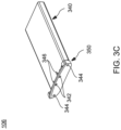
FIG. 3C is a top perspective view of the end-piece shown in FIG. 2 .
FIG. 4 is a further exploded perspective view of the one-piece casing and keypad shown in FIG. 3 .
FIG. 5 is a further exploded perspective view of the remote control and display shown in FIG. 1 .
FIG. 6 is a top perspective view of a remote control in accordance with another embodiment.
FIG. 7 is an exploded perspective view of the remote control of FIG. 6 .
FIG. 8A is a top perspective view of the one-piece casing shown in FIG. 7 .
FIG. 8B is a top perspective view of the chassis shown in FIG. 7 .
FIG. 8C is a top perspective view of the end-piece shown in FIG. 7 .
FIG. 9 is a further exploded perspective view of the one-piece casing and keypad shown in FIG. 8 .
FIG. 10 is a further exploded perspective view of the remote control and display shown in FIG. 6 .
DETAILED DESCRIPTION OF THE INVENTION
The present embodiments provide a remote control formed of a one-piece casing having a chassis inserted therein.
Unless the context clearly requires otherwise, throughout the description and the claims, the words ‘comprise’, ‘comprising’, and the like are to be construed in an inclusive sense as opposed to an exclusive or exhaustive sense; that is to say, in the sense of “including, but not limited to”.
LIST OF REFERENCE NUMBERS FOR THE MAJOR ELEMENTS IN THE DRAWING
The following is a list of the major elements in the drawings in numerical order.
    • 100 Remote Control Device
    • 102 One-Piece Casing
    • 104 Chassis
    • 106 End Insert
    • 108 Keypad
    • 110 Display/Touchscreen
    • 302 Opening
    • 304 Bosses
    • 306 Curved Edge
    • 308 Key Openings
    • 310 Display/Touchscreen Opening
    • 312 Inner Cavity
    • 314 Opening
    • 320 Chassis Body
    • 321 Chassis End Part
    • 322 Electrical Contacts
    • 324 Threaded Holes
    • 328 Key Contacts
    • 330 Mounting Clamps
    • 332 Chassis Surface
    • 334 Chassis Legs
    • 336 Curved Edge
    • 340 End Insert Body
    • 342 Docking Station Contacts
    • 344 Screw Holes
    • 346 Contacts
    • 350 End Part
    • 362 Keypad base
    • 368 Keys
    • 382 Spring Contact
    • 384 Spring Contact
    • 600 Remote Control Device
    • 602 One-Piece Casing
    • 604 Chassis
    • 606 End Insert
    • 608 Keypad
    • 610 Display/Touchscreen
    • 802 Opening
    • 804 Bosses
    • 806 Curved Edge
    • 808 Key Openings
    • 810 Display/Touchscreen Opening
    • 812 Inner Cavity
    • 814 Opening
    • 820 Chassis Body
    • 821 Chassis End Part
    • 822 Electrical Contacts
    • 824 Threaded Holes
    • 828 Key Contacts
    • 830 Mounting Clamps
    • 832 Chassis Surface
    • 834 Chassis Legs
    • 836 Curved Edge
    • 840 End Insert Body
    • 842 Docking Station Contacts
    • 844 Screw Holes
    • 846 Contacts
    • 850 End Part
    • 862 Keypad base
    • 868 Keys
    • 882 Spring Contact
    • 884 Spring Contact
MODE(S) FOR CARRYING OUT THE INVENTION
The embodiment described herein in the context of a remote control, but is not limited thereto, except as may be set forth expressly in the appended claims.
Referring first to FIG. 1 , a remote control device 100 is shown according to an embodiment. The remote control device 100 includes a one-piece casing 102. Disposed within the one-piece casing 102 are a chassis 104, an end insert 106, a keypad 108 and a display or touchscreen 110.
FIG. 2 is an exploded, perspective view of the remote control device 100 shown in FIG. 1 . The one-piece casing 102 is a hollow, one-piece housing and is typically formed of a single piece of metal or plastic. The chassis 104 is insertable into the one-piece casing 102 at one end thereof, and the end insert 106 is insertable into the one-piece casing 102 at another, opposing end.
FIG. 3A is a close-up view of the one-piece casing 102 shown in FIGS. 1 and 2 . An opening 314 is located at the one end of the one-piece casing 102 and opens into an inner cavity 312 within the hollow one-piece casing 102. The opening 314 is configured to receive the chassis 104 shown in FIG. 2 . A curved edge 306 is located at the one end of the one-piece casing 102 and has a shape that is complementary to a shape of a corresponding edge of the chassis 104.
Another opening 302 is disposed at the opposing end of the one-piece casing 102 and also opens into the inner cavity 312. The opening 302 is configured to receive the end insert 106 shown in FIG. 2 .
A pair of bosses 304 are located inside the opening 302 and are configured to receive threaded bolts or screws inserted into corresponding openings in the end insert 106 and in the chassis 104.
A plurality of various shaped key openings 308 are formed in a front surface of the one-piece casing 102 and are configured to receive the keys of the keypad 108.
A touchscreen opening 310 is also formed in the front surface of the one-piece casing 102 and is configured to receive the touchscreen 110.
FIG. 3B shows a close-up view of the chassis 104. The chassis 104 includes a chassis body 320 and an end part 321.
A pair of threaded openings 324 are located at one end of the chassis body 320 and are configured to receive threaded bolts or screws that are inserted into corresponding openings in the end insert 106 and into the bosses 304 of the one-piece casing 102. The screws are then turned to secure the chassis 104 and the end insert 106 to the one-piece casing 102. A pair of electrical contacts 322 are also located at this end of the chassis body 320.
A plurality of key contacts 328 are located on the chassis body 320 and connect to circuitry (not shown) located within the chassis body 320. The circuitry is located beneath the key contacts 328 and may also be located beneath the chassis surface 332 of the chassis body 320. Each key contact 328 is disposed at a location over which a corresponding key of the keypad 108 is disposed when the chassis body 320 is inserted.
A plurality of mounting clamps 330 are disposed on a surface 332 of the chassis body 320. The mounting clamps 330 are configured to receive and hold the touchscreen 110.
A pair of legs 334 extend below from the bottom of the chassis body 320 and support the chassis 104. The legs 334 are located at each side of the chassis body 320 may run the length of the chassis body 320. The outer surface of the legs 334 are shaped to conform to the shape of the sidewalls of the inner cavity 312 of the one-piece casing 102 and may contact the side walls of the inner cavity 312. When the chassis body 320 is inserted into the inner cavity 312 of the one-piece casing 102, the legs 334 cause the chassis body 320 to fit snugly against the side walls and bottom of the inner cavity 312 and hold the chassis body 320 in place within the inner cavity 312.
The end part 321 of the chassis 104 is located at an opposing end of the chassis 104 and is configured to remain outside of the one-piece casing 102 when the chassis body 320 is inserted into the inner cavity 312 of the one-piece casing 102. On each side of the end part 321, a curved edge 336 is formed. The curved edge 336 of the end part 321 and the curved edge 306 of the one-piece casing 102 have mutually complementary curvatures. That is, when the body 320 of the chassis 104 is inserted into the inner cavity 312 of the one-piece casing 102, the curved edge 306 of the casing 102 and the curved edge 336 of the end part 321 may abut closely against each other.
FIG. 3C shows a close-up view of the end insert 106. The end insert 106 includes a body 340, which may house a battery for the remote control device 100, and an end part 350.
A pair of screw holes 344 extend through the end part 350 and are aligned with the bosses 304 of the one-piece casing 102 and with the threaded holes 324 in the chassis body 320. That is, each screw hole 344, the boss 304 aligned to that screw hole 344, and the threaded hole 324 aligned to that boss 304, each receive a threaded screw or bolt (not shown) which, when tightened, helps secure the end part 350 of the end insert 106 to the chassis body 320 as well as helps secure the end part 350 against the one-piece casing 102. The tightening of the screws in this manner also cause the curved edge 306 of the one-piece casing 102 to press against the curved edge 336 of the end part 321 of the chassis 104. In this manner, the screws inserted into the openings 344 in the end part 350 hold the entire remote control device 100 together when the screws are tightened.
A pair of contacts 342 are also located on an outer side of the end part 350 and are electrically connected to contacts 346 located on an inner side of the end part 350. The contacts 342 are configured to receive the electrical contacts of a docking station (not shown) when an end of the remote control device 100 rests in the docking station. In this manner, power may be provided to the remote control device 100 and may be provided to recharge the battery.
FIG. 4 is further exploded perspective view showing the one-piece casing 102 separate from the keypad 108. The keypad 108 includes a keypad base 362 upon which are disposed a plurality of various shaped keys 368.
The keypad 108 is insertable through the opening 302 of the one-piece casing 102 and into the inner cavity 312. The plurality of key openings 308 formed in the front surface of the one-piece casing 102 are configured to receive the keys 368 so that when the keypad 108 is inserted into the inner cavity 312 and then raised up, the keys 368 extend into and through the corresponding the key openings 308.
FIG. 5 shows another exploded perspective view of the remote control device 100 that shows the insertion of a display or touchscreen 110 within an opening 310 in the one-piece casing 102.
The display or touchscreen 110 is inserted into the opening 310 of the one-piece casing 102 after the chassis body 320 and the end insert body 340 are inserted into the inner cavity 312 of the one-piece casing 102 and secured together. A plurality of mounting clamps 330 are located on the chassis surface 332, and when the display or touchscreen 110 is inserted into the opening 310, the mounting clamps 330 mate with corresponding structures in the display or touchscreen 110 and secure the display or touchscreen 110 to the chassis 104.
Two or more spring contacts 382, 384 are located between the display or touchscreen 110 and the chassis surface 314 and provide an electrical connection between the display or touchscreen 110 and the circuitry within the chassis body 320.
To assemble the remote control device 100, the keypad 108 is first inserted into the opening 302 of the one-piece casing 102, as shown in FIG. 4 , and then the keypad 108 is raised up within the inner cavity 312 of the one-piece casing 102 such that each key 368 of the keypad 108 extends through a corresponding one of the key openings 308 in the front surface of the one-piece casing 102.
Next, the chassis body 320 is inserted into the opening 314 of the one-piece casing 102, as shown in FIG. 2 , and the chassis body 314 is translated within the inner cavity 312 of the one-piece casing 102 until the curved edge 336 of the end part 321 of the chassis 104 abuts against the curved edge 306 of the one-piece casing 102.
Also, the body 340 of the end insert 106 is inserted into the opening 302 of the one-piece casing 102 until the end part 350 either fits inside or abuts against the one-piece casing 102. The body 340 of the end insert 106 may also rest underneath part of the chassis body 320 between the pair of legs 334.
Then, the threaded screws or bolts are inserted into the openings 344 in the end part 350 and through the bosses 304 into the threaded holes 324. Then, the threaded screws or bolts are turned until the end insert 106 and the chassis 104 are each secured to the one-piece casing 102.
Thereafter, the display or touchscreen 110 is inserted into the opening 310 of the one-piece casing 102 and secured by the mounting clamps 330 to hold the display or touchscreen 110. In this manner, assembly of the remote control device 100 is completed.
FIG. 6 shows a remote control device 600 according to another embodiment in which additional keys are provided in place of a portion of the display or touchscreen of the remote control device 100.
The remote control device 600 includes a one-piece casing 602. Disposed within the one-piece casing 602 are a chassis 604, an end insert 606, a keypad 608 and a display or touchscreen 610.
FIG. 7 is an exploded, perspective view of the remote control device 600 shown in FIG. 6 . The one-piece casing 602 is a hollow, one-piece housing and is typically formed of a single piece of metal or plastic. The chassis 604 is insertable into the one-piece casing 602 at one end thereof, and the end insert 606 is insertable into the one-piece casing 602 at another, opposing end.
FIG. 8A is a close-up view of the one-piece casing 602 shown in FIGS. 6 and 7 . An opening 814 is located at the one end of the one-piece casing 602 and opens into an inner cavity 812 within the hollow one-piece casing 602. The opening 814 is configured to receive the chassis 604 shown in FIG. 7 . A curved edge 806 is located at the one end of the one-piece casing 602 and has a shape that is complementary to a shape of a corresponding edge of the chassis 604.
Another opening 802 is disposed at the opposing end of the one-piece casing 602 and also opens into the inner cavity 812. The opening 802 is configured to receive the end insert 606 shown in FIG. 7 .
A pair of bosses 804 are located inside the opening 802 and are configured to receive threaded bolts or screws inserted into corresponding openings in the end insert 606 and in the chassis 604.
A plurality of various shaped key openings 808 are formed in a front surface of the one-piece casing 602 and are configured to receive the keys of the keypad 608.
A touchscreen opening 810 is also formed in the front surface of the one-piece casing 602 and is configured to receive the touchscreen 610.
FIG. 8B shows a close-up view of the chassis 604. The chassis 604 includes a chassis body 820 and an end part 821.
A pair of threaded openings 824 are located at one end of the chassis body 820 and are configured to receive threaded bolts or screws that are inserted into corresponding openings in the end insert 606 and into the bosses 804 of the one-piece casing 602. The screws are then turned to secure the chassis 604 and the end insert 606 to the one-piece casing 602. A pair of electrical contacts 822 are also located at this end of the chassis body 820.
A plurality of key contacts 828 are located on the chassis body 820 and connect to circuitry (not shown) located within the chassis body 820. The circuitry is located beneath the key contacts 828 and may also be located beneath the chassis surface 832 of the chassis body 820. Each key contact 828 is disposed at a location over which a corresponding key of the keypad 608 is disposed when the chassis body 820 is inserted.
A plurality of mounting clamps 830 are disposed on a surface 832 of the chassis body 820. The mounting clamps 830 are configured to receive and hold the touchscreen 610.
A pair of legs 834 extend below from the bottom of the chassis body 820 and support the chassis 604. The legs 834 are located at each side of the chassis body 820 may run the length of the chassis body 820. The outer surface of the legs 834 are shaped to conform to the shape of the sidewalls of the inner cavity 812 of the one-piece casing 602 and may contact the side walls of the inner cavity 812. When the chassis body 820 is inserted into the inner cavity 812 of the one-piece casing 602, the legs 834 cause the chassis body 820 to fit snugly against the side walls and bottom of the inner cavity 812 and hold the chassis body 820 in place within the inner cavity 812.
The end part 821 of the chassis 604 is located at an opposing end of the chassis 604 and is configured to remain outside of the one-piece casing 602 when the chassis body 820 is inserted into the inner cavity 812 of the one-piece casing 602. On each side of the end part 821, a curved edge 836 is formed. The curved edge 836 of the end part 821 and the curved edge 806 of the one-piece casing 602 have mutually complementary curvatures. That is, when the body 820 of the chassis 604 is inserted into the inner cavity 812 of the one-piece casing 602, the curved edge 806 of the casing 602 and the curved edge 836 of the end part 821 may abut closely against each other.
FIG. 8C shows a close-up view of the end insert 606. The end insert 606 includes a body 840, which may house a battery for the remote control device 600, and an end part 850.
A pair of screw holes 844 extend through the end part 850 and are aligned with the bosses 804 of the one-piece casing 602 and with the threaded holes 824 in the chassis body 820. That is, each screw hole 844, the boss 804 aligned to that screw hole 844, and the threaded hole 824 aligned to that boss 804, each receive a threaded screw or bolt (not shown) which, when tightened, helps secure the end part 850 of the end insert 606 to the chassis body 820 as well as helps secure the end part 850 against the one-piece casing 602. The tightening of the screws in this manner also cause the curved edge 806 of the one-piece casing 602 to press against the curved edge 836 of the end part 821 of the chassis 604. In this manner, the screws inserted into the openings 844 in the end part 850 hold the entire remote control device 600 together when the screws are tightened.
A pair of contacts 842 are also located on an outer side of the end part 850 and are electrically connected to contacts 846 located on an inner side of the end part 850. The contacts 842 are configured to receive the electrical contacts of a docking station (not shown) when an end of the remote control device 600 rests in the docking station. In this manner, power may be provided to the remote control device 600 and may be provided to recharge the battery.
FIG. 9 is further exploded perspective view showing the one-piece casing 602 separate from the keypad 608. The keypad 608 includes a keypad base 862 upon which are disposed a plurality of various shaped keys 868.
The keypad 608 is insertable through the opening 802 of the one-piece casing 602 and into the inner cavity 812. The plurality of key openings 808 formed in the front surface of the one-piece casing 602 are configured to receive the keys 868 so that when the keypad 608 is inserted into the inner cavity 812 and then raised up, the keys 868 extend into and through the corresponding the key openings 808.
FIG. 60 shows another exploded perspective view of the remote control device 600 that shows the insertion of a display or touchscreen 610 within an opening 810 in the one-piece casing 602.
The display or touchscreen 610 is inserted into the opening 810 of the one-piece casing 602 after the chassis body 820 and the end insert body 840 are inserted into the inner cavity 812 of the one-piece casing 602 and secured together. A plurality of mounting clamps 830 are located on the chassis surface 832, and when the display or touchscreen 610 is inserted into the opening 810, the mounting clamps 830 mate with corresponding structures in the display or touchscreen 610 and secure the display or touchscreen 610 to the chassis 604.
Two or more spring contacts 882, 884 are located between the display or touchscreen 610 and the chassis surface 814 and provide an electrical connection between the display or touchscreen 610 and the circuitry within the chassis body 820.
To assemble the remote control device 600, the keypad 608 is first inserted into the opening 802 of the one-piece casing 602, as shown in FIG. 9 , and then the keypad 608 is raised up within the inner cavity 812 of the one-piece casing 602 such that each key 868 of the keypad 608 extends through a corresponding one of the key openings 808 in the front surface of the one-piece casing 602.
Next, the chassis body 820 is inserted into the opening 814 of the one-piece casing 602, as shown in FIG. 7 , and the chassis body 814 is translated within the inner cavity 812 of the one-piece casing 602 until the curved edge 836 of the end part 821 of the chassis 604 abuts against the curved edge 806 of the one-piece casing 602.
Also, the body 840 of the end insert 606 is inserted into the opening 802 of the one-piece casing 602 until the end part 850 either fits inside or abuts against the one-piece casing 602. The body 840 of the end insert 606 may also rest underneath part of the chassis body 820 between the pair of legs 834.
Then, the threaded screws or bolts are inserted into the openings 844 in the end part 850 and through the bosses 804 into the threaded holes 824. Then, the threaded screws or bolts are turned until the end insert 606 and the chassis 604 are each secured to the one-piece casing 602.
Thereafter, the display or touchscreen 610 is inserted into the opening 810 of the one-piece casing 602 and secured by the mounting clamps 830 to hold the display or touchscreen 610. In this manner, assembly of the remote control device 600 is completed.
In this manner, each of the remote controls 100 and 600 of the embodiments provides an arrangement of parts that are easier to assemble and simpler to service.
INDUSTRIAL APPLICABILITY
To solve the aforementioned problems, the present embodiments provide a remote control with a one-piece casing and chassis.
It should be understood that this description is not intended to limit the embodiments. On the contrary, the embodiments are intended to cover alternatives, modifications, and equivalents, which are included in the spirit and scope of the embodiments as defined by the appended claims. Further, in the detailed description of the embodiments, numerous specific details are set forth to provide a comprehensive understanding of the claimed embodiments. However, one skilled in the art would understand that various embodiments may be practiced without such specific details.
Although the features and elements of aspects of the embodiments are described as being in particular combinations, each feature or element may be used alone, without the other features and elements of the embodiments, or in various combinations with or without other features and elements disclosed herein.
This written description uses examples of the subject matter disclosed to enable any person skilled in the art to practice the same, including making and using any devices or systems and performing any incorporated methods. The patentable scope of the subject matter is defined by the claims, and may include other examples that occur to those skilled in the art. Such other examples are intended to be within the scope of the claims.
The above-described embodiments are intended to be illustrative in all respects, rather than restrictive, of the embodiments. Thus, the embodiments are capable of many variations in detailed implementation that may be derived from the description contained herein by a person skilled in the art. No element, act, or instruction used in the description of the present application should be construed as critical or essential to the embodiments unless explicitly described as such. Also, as used herein, the article “a” is intended to include one or more items.
In addition, the above disclosed methods are not meant to limit the aspects of the embodiments, or to suggest that the aspects of the embodiments should be implemented following the aforementioned methods. The purpose of the aforementioned methods is to facilitate the understanding of one or more aspects of the embodiments and to provide the reader with one or many possible implementations of the processed discussed herein. It should be understood by one of ordinary skill in the art that the steps of the aforementioned methods may be performed in a different order and that some steps may be eliminated or substituted.
All United States patents and applications, foreign patents, and publications discussed above are hereby incorporated herein by reference in their entireties.
ALTERNATE EMBODIMENTS
Alternate embodiments may be devised without departing from the spirit or the scope of the embodiments.

Claims (20)

What is claimed is:
1. A remote control device, comprising:
(a) a single-piece casing having formed therein a first opening disposed at one end, a second opening disposed at another end, an inner cavity disposed between the first opening and the second opening, a front opening disposed in a front surface of the casing, and a plurality of key openings disposed in the front surface;
(b) a keypad configured to be disposed within the inner cavity, and having a plurality of keys arranged on a surface of the keypad, the plurality of keys being configured to extend through the plurality of key openings;
(c) a chassis having a body configured to be inserted into the inner cavity though the first opening and disposed in the inner cavity below the keypad, the chassis having an end part configured to be disposed outside of the casing, an edge of the end part being configured to abut against the one end of the casing; and
(d) an end insert having a body configured to be inserted into the inner cavity though the second opening and disposed in the inner cavity below the body of the chassis, the end insert having an end part configured to be located at the another end of the casing.
2. The remote control device of claim 1, wherein
(a) the body of the chassis includes at least one threaded opening disposed at an end opposite to the end part of the chassis,
(b) the end part of the end insert includes at least one opening aligned with the at least one threaded opening of the chassis,
(c) whereby upon the body of the chassis and the body of the end insert being inserted into the inner cavity of the casing, a threaded screw inserted into the at least one opening of the end insert and turned into the at least one threaded opening of the chassis secures both the chassis and the end insert against the casing.
3. The remote control device of claim 1, further comprising
(a) a display configured to be inserted into the front opening of the casing.
4. The remote control device of claim 3, further comprising
(a) at least one electrical contact configured to electrically connect circuitry disposed within the body of the chassis to the display, and
(b) at least one mounting clamp disposed on a front surface of the body of the chassis and configured to secure the display to the chassis upon insertion of the display into the front opening of the casing.
5. The remote control device of claim 1, wherein
(a) each one of the plurality of key openings in the casing is configured to receive at least one of the keys of the keypad.
6. The remote control device of claim 1, wherein
(a) the body of the chassis includes a plurality of key contacts having an arrangement corresponding to an arrangement of the keys of the keypad,
(b) whereby upon the keypad being inserted into the inner cavity of the casing, and the body of the chassis then being inserted into the inner cavity of the casing, each one of the plurality of keys of the keypad overlies a corresponding one of the plurality of key contacts of the chassis.
7. The remote control device of claim 1, wherein
(a) the body of the chassis includes a pair of legs extending below from the body of the chassis, the pair of legs being configured to support the body of the chassis within the inner cavity.
8. The remote control device of claim 7, wherein
(a) each leg of the pair of legs includes a surface that conforms to a shape of, and contacts with, at least a portion of a sidewall of the inner cavity of the casing.
9. The remote control device of claim 7, wherein
(a) the pair of legs provide a spacing between at least a portion of the body of the chassis and a bottom surface of the inner cavity of the casing, and
(b) at least part of the body of the end insert is configured to be inserted into the spacing.
10. The remote control device of claim 1, wherein
(a) the one end of the casing includes at least one curved edge,
(b) the end part of the chassis includes at least another curved edge, and
(c) the at least one curved edge of the casing and the at least another curved edge of the end part have mutually complementary shapes such that the curved edge and the another curved edge abut against each other upon the body of the chassis being inserted into the inner cavity of the casing.
11. The remote control device of claim 1, wherein
(a) the body portion of the end insert is configured to hold a battery.
12. The remote control device of claim 1, further comprising
(a) at least one electrical contact disposed on an inner surface of the end part of the end insert, and
(b) at least another electrical contact disposed at an adjacent end of the body of the chassis,
(c) the at least one electrical contact and the at least another electrical contact being arranged to contact each other upon the body of the chassis and the body of the end insert being inserted into the inner cavity of the casing.
13. The remote control device of claim 12, further comprising
(a) at least one electrical contact disposed on an outer surface of the end part of the end insert, and extending through the end part to the at least one electrical contact on the inner surface of the end part,
(b) the at least one opening in the outer surface of the end part being configured to connect to an electrical contact of an external docking station.
14. A remote control device, comprising:
(a) a single-piece casing having formed therein a first opening disposed at one end, a second opening disposed at another end, and an inner cavity disposed between the first opening and the second opening;
(b) a chassis having a body configured to be inserted into the inner cavity though the first opening and having an end part configured to be disposed outside of the casing, and edge of the end part being configured to abut against the one end of the casing; and
(c) an end insert having a body configured to be inserted into the inner cavity though the second opening and having an end part configured to be disposed at the another end of the casing;
(d) wherein
(1) the body of the chassis includes at least one threaded opening disposed at an end opposite to the end part of the chassis,
(2) the end part of the end insert includes at least one opening aligned with the at least one threaded opening of the chassis, whereby
(3) upon the body of the chassis and the end insert being inserted into the inner cavity of the casing, a threaded screw inserted into the at least one opening of the end insert and turned into the at least one threaded opening of the chassis secures both the chassis and the end insert against the casing.
15. The remote control device of claim 14, wherein
(a) the casing includes a front opening disposed in a front surface of the casing, and
(b) the remote control device further comprises
(1) a display configured to be inserted into the front opening of the casing,
(2) at least one electrical contact configured to electrically connect circuitry disposed within the body of the chassis to the display, and
(3) at least one mounting clamp disposed on a front surface of the body of the chassis and configured to secure the display to the chassis upon insertion of the display into the front opening of the casing.
16. The remote control device of claim 14, further comprising
(a) a keypad having a plurality of keys arranged on a surface of the keypad, the keypad being configured to be inserted into the inner cavity of the casing prior to the body of the chassis and the body of the end insert being inserted into the inner cavity.
17. The remote control device of claim 16, wherein
(a) the casing includes a plurality of key openings disposed in a front surface of the casing, each one of the plurality of key openings being configured to receive at least one of the keys of the keypad.
18. The remote control device of claim 16, wherein
(a) the body of the chassis includes a plurality of key contacts having an arrangement corresponding to an arrangement of the keys of the keypad, and
(b) upon the keypad being inserted into the inner cavity of the casing, and the body of the chassis then being inserted into the inner cavity of the casing, each one of the plurality of keys of the keypad overlies a corresponding one of the plurality of key contacts of the chassis.
19. The remote control device of claim 14, wherein
(a) the body of the chassis includes a pair of legs extending below from the body of the chassis, the pair of legs being configured to support the body of the chassis within the inner cavity and providing a spacing between at least a portion of the body of the chassis and a bottom surface of the inner cavity of the casing,
(b) at least part of the body of the end insert is configured to be inserted into the spacing, and
(c) each leg of the pair of legs includes a surface that conforms to a shape of, and contacts with, at least a portion of a sidewall of the inner cavity of the casing.
20. A remote control device, comprising:
(a) a single-piece casing having formed therein a first opening disposed at one end, a second opening disposed at another end, an inner cavity disposed between the first opening and the second opening, a front opening disposed in a front surface of the casing, and a plurality of key openings disposed in the front surface;
(b) a keypad configured to be disposed within the inner cavity, and having a plurality of keys arranged on a surface of the keypad, the plurality of keys being configured to extend through the plurality of key openings;
(c) a chassis having a body configured to be inserted into the inner cavity though the first opening and disposed in the inner cavity below the keypad, the chassis having an end part configured to be disposed outside of the casing, an edge of the end part being configured to abut against the one end of the casing, wherein
(1) the body of the chassis includes a pair of legs extending below from the body of the chassis, the pair of legs being configured to support the body of the chassis within the inner cavity and providing a spacing between at least a portion of the body of the chassis and a bottom surface of the inner cavity of the casing,
(2) each leg of the pair of legs includes a surface that conforms to a shape of, and contacts with, at least a portion of a sidewall of the inner cavity of the casing, and
(3) the body of the chassis includes at least one threaded opening disposed at an end opposite to the end part of the chassis,
(d) an end insert having a body configured to be inserted into the inner cavity though the second opening and disposed in the inner cavity in the spacing below the body of the chassis, the end insert having an end part configured to be located at the another end of the casing, wherein
(1) the end part of the end insert includes at least one opening aligned with the at least one threaded opening of the chassis,
(2) whereby upon the body of the chassis and the end insert being inserted into the inner cavity of the casing, a threaded screw inserted into the at least one opening of the end insert and turned into the at least one threaded opening of the chassis secures both the chassis and the end insert against the casing; and
(e) a display configured to be inserted into the front opening of the casing, wherein the remote control device further includes
(1) at least one electrical contact configured to electrically connect circuitry disposed within the body of the chassis to the display, and
(2) at least one mounting clamp disposed on a front surface of the body of the chassis and configured to secure the display to the chassis upon insertion of the display into the front opening of the casing.
US18/125,293 2023-03-23 2023-03-23 Remote control with one-piece casing and chassis Active 2043-11-08 US12232275B2 (en)

Priority Applications (2)

Application Number Priority Date Filing Date Title
US18/125,293 US12232275B2 (en) 2023-03-23 2023-03-23 Remote control with one-piece casing and chassis
US19/017,852 US20250151209A1 (en) 2023-03-23 2025-01-13 Remote control with one-piece casing and chassis

Applications Claiming Priority (1)

Application Number Priority Date Filing Date Title
US18/125,293 US12232275B2 (en) 2023-03-23 2023-03-23 Remote control with one-piece casing and chassis

Related Child Applications (1)

Application Number Title Priority Date Filing Date
US19/017,852 Continuation US20250151209A1 (en) 2023-03-23 2025-01-13 Remote control with one-piece casing and chassis

Publications (2)

Publication Number Publication Date
US20240324111A1 US20240324111A1 (en) 2024-09-26
US12232275B2 true US12232275B2 (en) 2025-02-18

Family

ID=92802553

Family Applications (2)

Application Number Title Priority Date Filing Date
US18/125,293 Active 2043-11-08 US12232275B2 (en) 2023-03-23 2023-03-23 Remote control with one-piece casing and chassis
US19/017,852 Pending US20250151209A1 (en) 2023-03-23 2025-01-13 Remote control with one-piece casing and chassis

Family Applications After (1)

Application Number Title Priority Date Filing Date
US19/017,852 Pending US20250151209A1 (en) 2023-03-23 2025-01-13 Remote control with one-piece casing and chassis

Country Status (1)

Country Link
US (2) US12232275B2 (en)

Families Citing this family (1)

* Cited by examiner, † Cited by third party
Publication number Priority date Publication date Assignee Title
USD1063869S1 (en) * 2023-03-23 2025-02-25 Crestron Electronics, Inc. Remote control

Citations (120)

* Cited by examiner, † Cited by third party
Publication number Priority date Publication date Assignee Title
IL64833A (en) 1982-01-22 1985-09-29 Israel Goldfarb Hand-manipulatable threedimensional puzzle
USD354059S (en) 1992-12-03 1995-01-03 Discovery Communications, Inc. Remote control unit
US5867772A (en) * 1996-03-08 1999-02-02 Ericsson, Inc. Cellular telephone assembly and method for assembling a cellular telephone
USD448358S1 (en) 2000-04-27 2001-09-25 Interlink Electronics, Inc. Remote control
USD450662S1 (en) 2000-09-25 2001-11-20 Saitek Ltd. Remote control device
USD451891S1 (en) 2000-08-22 2001-12-11 Deere & Company Implement depth control and display
US20030095048A1 (en) 2001-11-19 2003-05-22 Samsung Electronics Co., Ltd. Remote controller
USD489361S1 (en) 2002-10-09 2004-05-04 Interlink Electronics, Inc. Remote control
USD513498S1 (en) 2004-02-25 2006-01-10 Openpeak, Inc. Remote control
USD515041S1 (en) 2004-12-10 2006-02-14 Samsung Electronics Co., Ltd. Remote controller for electric home appliances
USD515557S1 (en) 2003-09-16 2006-02-21 Intel Corporation Remote control
USD520495S1 (en) 2005-09-01 2006-05-09 Amx Llc Remote controller
USD521459S1 (en) 2004-12-10 2006-05-23 Samsung Electronics Co., Ltd. Remote controller for electric home appliances
USD524298S1 (en) 2004-09-07 2006-07-04 Control4 Corporation Hand-held remote control
USD531137S1 (en) 2006-01-12 2006-10-31 Leviton Manufacturing Co., Inc. Primary controller
USD531585S1 (en) 2005-04-26 2006-11-07 Ruwido Austria Gesellschaft M.B.H. Remote control
USD531964S1 (en) 2002-07-22 2006-11-14 Koninklijke Philips Electronics, N.V. Remote control unit
US20070054651A1 (en) 2005-09-07 2007-03-08 Amx, Llc Power management for electronic devices
USD538788S1 (en) 2004-01-06 2007-03-20 Bose Corporation Remote control
USD543196S1 (en) 2005-08-19 2007-05-22 Openpeak, Inc. Remote controller
USD544467S1 (en) 2006-02-14 2007-06-12 Sony Corporation Remote controller
USD548195S1 (en) 2005-06-28 2007-08-07 Somfy Sas Remote control
USD548727S1 (en) 2006-02-03 2007-08-14 Kabushiki Kaisha Toshiba Remote controller
USD549665S1 (en) 2006-11-30 2007-08-28 Light-Art Technology Co., Ltd. Remote controller for computer
USD550213S1 (en) 2006-01-10 2007-09-04 Sony Corporation Remote controller
USD552601S1 (en) 2006-05-23 2007-10-09 Sony Corporation Remote controller for optical disc player
USD555107S1 (en) 2006-07-25 2007-11-13 Samsung Electronics Co., Ltd. Remote controller for electric home appliances
USD559231S1 (en) 2005-12-20 2008-01-08 Openpeak Inc. Remote controller
USD559202S1 (en) 2006-02-10 2008-01-08 Samsung Electronics Co., Ltd. Remote controller
USD565555S1 (en) 2006-09-21 2008-04-01 Sony Computer Entertainment Inc. Remote controller
USD568298S1 (en) 2006-12-06 2008-05-06 General Instrument Corporation Remote control
USD572203S1 (en) 2007-12-21 2008-07-01 Samsung Electronics Co., Ltd. Control panel for a composite device
USD583363S1 (en) 2008-07-23 2008-12-23 Samsung Electronics Co., Ltd. Remote controller for television receiver
USD584718S1 (en) 2004-11-30 2009-01-13 Vkr Holding A/S Remote control
USD587689S1 (en) 2007-10-26 2009-03-03 Openpeak Inc. Remote controller
US7515431B1 (en) 2004-07-02 2009-04-07 Apple Inc. Handheld computing device
USD594850S1 (en) 2007-02-01 2009-06-23 Koninklijke Philips Electronics N.V. Remote control unit
USD602474S1 (en) 2009-01-07 2009-10-20 Cisco Technology, Inc. Remote controller
USD603843S1 (en) 2009-03-30 2009-11-10 EchoStar Technologies, L.L.C. Entertainment device remote control
USD605634S1 (en) 2007-09-05 2009-12-08 Russound/Fmp, Inc. Wireless remote control device
USD607846S1 (en) 2008-08-13 2010-01-12 Koninklijke Philips Electronics N.V. Remote control unit
US20100033498A1 (en) 2008-08-06 2010-02-11 Kabushiki Kaisha Toshiba Electronic apparatus having display device
USD611432S1 (en) 2008-12-18 2010-03-09 Simu Remote control
USD611456S1 (en) 2009-10-02 2010-03-09 Hannstar Display Corp. Remote controller
USD614607S1 (en) 2009-09-14 2010-04-27 Kabushiki Kaisha Toshiba Remote controller for television receivers
USD615965S1 (en) 2007-06-14 2010-05-18 Sony Corporation Remote control
US7724532B2 (en) 2004-07-02 2010-05-25 Apple Inc. Handheld computing device
USD617747S1 (en) 2009-07-27 2010-06-15 Daikin Industries Ltd. Remote control for air conditioner
USD618628S1 (en) 2009-07-27 2010-06-29 Daikin Industries Ltd. Remote control for air conditioner
USD622703S1 (en) 2009-11-11 2010-08-31 Koninklijke Philips Electronics N.V. Remote control unit
USD625693S1 (en) 2009-08-14 2010-10-19 Somfy Sas Remote control
USD626531S1 (en) 2006-09-06 2010-11-02 Amx Llc Remote control
USD628982S1 (en) 2009-10-26 2010-12-14 Koninklijke Philips Electronics N.V. Remote control unit
USD630188S1 (en) 2010-02-01 2011-01-04 Koninklijke Philips Electronics N.V. Remote control unit
USD631871S1 (en) 2010-08-04 2011-02-01 John Michael Demskie Remote control
USD632264S1 (en) 2010-06-16 2011-02-08 Samsung Electronics Co., Ltd. Remote controller for air conditioner
USD639276S1 (en) 2010-07-22 2011-06-07 Koninklijke Philips Electronics N.V. Remote control unit
USD639278S1 (en) 2010-12-15 2011-06-07 Hannstar Display Corp. Remote control
USD639750S1 (en) 2010-05-11 2011-06-14 Daikin Industries Ltd. Remote control for air conditioner
USD641734S1 (en) 2009-08-12 2011-07-19 Hannstar Display Corp. Remote control
USD647509S1 (en) 2010-09-08 2011-10-25 Fm Marketing Gmbh Wireless remote control
USD648285S1 (en) 2011-04-28 2011-11-08 Daikin Industries Ltd. Controller for air-conditioner
USD652820S1 (en) 2010-09-02 2012-01-24 Koninklijke Philips Electronics N.V. Remote control unit
USD653240S1 (en) 2010-10-19 2012-01-31 Sharp Kabushiki Kaisha Remote controller for television set
USD654055S1 (en) 2009-07-28 2012-02-14 Lg Electronics Inc. Television receiver remote controller
USD654477S1 (en) 2010-07-06 2012-02-21 Fm Marketing Gmbh Remote control
USD654478S1 (en) 2011-07-01 2012-02-21 Samsung Electronics Co., Ltd. Remote controller for TV receiver
USD656488S1 (en) 2011-05-18 2012-03-27 Seiko Epson Corporation Remote controller for projector
USD656487S1 (en) 2011-08-29 2012-03-27 Savant Systems, Llc Hand held remote
USD657754S1 (en) 2011-04-05 2012-04-17 Daikin Industries Ltd. Controller for air conditioner
USD664947S1 (en) 2011-10-21 2012-08-07 Samsung Electronics Co., Ltd. Remote controller
USD665382S1 (en) 2011-03-18 2012-08-14 Lg Electronics Inc. Remote control for projectors
US20120212678A1 (en) 2011-02-22 2012-08-23 Chien-Fa Wang Multimedia television remote control having a cursor control function
USD670658S1 (en) 2012-01-05 2012-11-13 L & P Property Management Company Furniture remote control
USD671529S1 (en) 2007-09-18 2012-11-27 Logitech Europe S.A. Remote control
USD673934S1 (en) 2011-10-11 2013-01-08 Kt Corporation Remote control
USD679266S1 (en) 2011-10-11 2013-04-02 Kt Corporation Remote control
USD689468S1 (en) 2012-05-22 2013-09-10 Kt Corporation Wireless remote control
USD692417S1 (en) 2012-11-07 2013-10-29 Hon Hai Precision Industry Co., Ltd. Remote controller
USD697055S1 (en) 2013-04-09 2014-01-07 VIZIO Inc. Remote control
USD697874S1 (en) 2013-03-15 2014-01-21 Select Comfort Corporation Remote control
USD703187S1 (en) 2013-02-25 2014-04-22 Fm Marketing Gmbh Remote control
USD708589S1 (en) 2013-09-19 2014-07-08 Daikin Industries Ltd. Remote control for air conditioner
USD714740S1 (en) 2013-09-18 2014-10-07 Savant Systems, Llc Wi-fi remote control
USD722044S1 (en) 2012-11-06 2015-02-03 Isaac S. Daniel Electronic communication device with a touchscreen display for reviewing advertisements
USD724062S1 (en) 2014-10-02 2015-03-10 Crestron Electronics Inc. Hand-held remote control
USD724568S1 (en) 2014-02-04 2015-03-17 Koninklijke Philips N.V. Remote control unit
USD726164S1 (en) 2014-10-02 2015-04-07 Crestron Electronics Inc. Hand-held remote control
USD735718S1 (en) 2013-04-23 2015-08-04 Shenzhen Riitek Technology Co., Ltd. Mini keyboard
USD738883S1 (en) 2013-07-13 2015-09-15 Shenzhen Riitek Technology Co., Ltd. Mini keyboard
USD743915S1 (en) 2012-07-12 2015-11-24 Mitsubishi Electric Corporation Remote controller for air conditioner
USD754105S1 (en) 2014-06-09 2016-04-19 Comcast Cable Communications, Llc Remote with illuminated region
USD755758S1 (en) 2013-05-22 2016-05-10 Fm Marketing Gmbh Remote control
USD760699S1 (en) 2014-07-04 2016-07-05 Home Control Singapore Pte. Ltd. Remote control unit
USD788743S1 (en) 2015-07-20 2017-06-06 Lg Electronics Inc. Remote control
USD795444S1 (en) 2015-11-13 2017-08-22 Healthmate International, Inc. Electronic massager
USD809485S1 (en) 2016-12-14 2018-02-06 Vizio Inc Remote control
USD823834S1 (en) 2016-11-01 2018-07-24 Huawei Technologies Co., Ltd. Remote control
USD825497S1 (en) 2016-09-12 2018-08-14 Mitsubishi Electric Corporation Input device for industrial equipment
USD847793S1 (en) 2017-09-14 2019-05-07 Crestron Electronics, Inc. Remote control
USD847792S1 (en) 2017-09-14 2019-05-07 Crestron Electronics, Inc. Remote control
USD848977S1 (en) 2018-01-09 2019-05-21 Shenzhen Riitek Technology Co., Ltd. Remote control
USD857661S1 (en) 2017-11-29 2019-08-27 Toto, Ltd. Remote controller for toilet seat with bidet
USD866526S1 (en) 2017-10-18 2019-11-12 Tech4Home, Lda. Remote control wireless
USD898704S1 (en) 2017-09-14 2020-10-13 Crestron Electronics, Inc. Remote control
USD898705S1 (en) 2017-09-14 2020-10-13 Crestron Electronics, Inc. Remote control
USD914643S1 (en) 2018-03-29 2021-03-30 Beijing Xiaomi Mobile Software Co., Ltd. Remote controller
USD923605S1 (en) 2019-09-09 2021-06-29 Savant Systems, Inc. Hand held remote
USD923606S1 (en) 2019-09-09 2021-06-29 Savant Systems, Inc. Hand held remote
USD939452S1 (en) 2019-04-03 2021-12-28 Etekcity Corporation Remote control for massage apparatus
USD952607S1 (en) 2020-03-30 2022-05-24 Universal Remote Control, Inc. Remote control
USD958760S1 (en) 2020-07-29 2022-07-26 Lg Electronics Inc. Remote control for air conditioner
USD980192S1 (en) 2021-02-24 2023-03-07 AVA Innovations AG Remote control
USD980822S1 (en) 2022-08-26 2023-03-14 Yuxian Lin TV remote control device
USD997913S1 (en) 2021-08-31 2023-09-05 Comcast Cable Communications, Llc Wireless remote control device
USD999178S1 (en) 2022-05-20 2023-09-19 Gree Electric Appliances, Inc. Of Zhuhai Remote control for air conditioner
USD1005264S1 (en) 2021-08-05 2023-11-21 Crestron Electronics, Inc. Remote control
USD1005292S1 (en) 2021-08-05 2023-11-21 Crestron Electronics, Inc. Remote control
USD1011313S1 (en) 2021-12-10 2024-01-16 Somfy Activites Sa Remote control (wireless)
USD1049078S1 (en) 2023-03-23 2024-10-29 Crestron Electronics, Inc. Remote control

Patent Citations (121)

* Cited by examiner, † Cited by third party
Publication number Priority date Publication date Assignee Title
IL64833A (en) 1982-01-22 1985-09-29 Israel Goldfarb Hand-manipulatable threedimensional puzzle
USD354059S (en) 1992-12-03 1995-01-03 Discovery Communications, Inc. Remote control unit
US5867772A (en) * 1996-03-08 1999-02-02 Ericsson, Inc. Cellular telephone assembly and method for assembling a cellular telephone
USD448358S1 (en) 2000-04-27 2001-09-25 Interlink Electronics, Inc. Remote control
USD451891S1 (en) 2000-08-22 2001-12-11 Deere & Company Implement depth control and display
USD450662S1 (en) 2000-09-25 2001-11-20 Saitek Ltd. Remote control device
US20030095048A1 (en) 2001-11-19 2003-05-22 Samsung Electronics Co., Ltd. Remote controller
USD531964S1 (en) 2002-07-22 2006-11-14 Koninklijke Philips Electronics, N.V. Remote control unit
USD489361S1 (en) 2002-10-09 2004-05-04 Interlink Electronics, Inc. Remote control
USD515557S1 (en) 2003-09-16 2006-02-21 Intel Corporation Remote control
USD538788S1 (en) 2004-01-06 2007-03-20 Bose Corporation Remote control
USD513498S1 (en) 2004-02-25 2006-01-10 Openpeak, Inc. Remote control
US7724532B2 (en) 2004-07-02 2010-05-25 Apple Inc. Handheld computing device
US7515431B1 (en) 2004-07-02 2009-04-07 Apple Inc. Handheld computing device
USD524298S1 (en) 2004-09-07 2006-07-04 Control4 Corporation Hand-held remote control
USD584718S1 (en) 2004-11-30 2009-01-13 Vkr Holding A/S Remote control
USD521459S1 (en) 2004-12-10 2006-05-23 Samsung Electronics Co., Ltd. Remote controller for electric home appliances
USD515041S1 (en) 2004-12-10 2006-02-14 Samsung Electronics Co., Ltd. Remote controller for electric home appliances
USD531585S1 (en) 2005-04-26 2006-11-07 Ruwido Austria Gesellschaft M.B.H. Remote control
USD548195S1 (en) 2005-06-28 2007-08-07 Somfy Sas Remote control
USD543196S1 (en) 2005-08-19 2007-05-22 Openpeak, Inc. Remote controller
USD520495S1 (en) 2005-09-01 2006-05-09 Amx Llc Remote controller
US20070054651A1 (en) 2005-09-07 2007-03-08 Amx, Llc Power management for electronic devices
USD559231S1 (en) 2005-12-20 2008-01-08 Openpeak Inc. Remote controller
USD550213S1 (en) 2006-01-10 2007-09-04 Sony Corporation Remote controller
USD531137S1 (en) 2006-01-12 2006-10-31 Leviton Manufacturing Co., Inc. Primary controller
USD548727S1 (en) 2006-02-03 2007-08-14 Kabushiki Kaisha Toshiba Remote controller
USD559202S1 (en) 2006-02-10 2008-01-08 Samsung Electronics Co., Ltd. Remote controller
USD544467S1 (en) 2006-02-14 2007-06-12 Sony Corporation Remote controller
USD552601S1 (en) 2006-05-23 2007-10-09 Sony Corporation Remote controller for optical disc player
USD555107S1 (en) 2006-07-25 2007-11-13 Samsung Electronics Co., Ltd. Remote controller for electric home appliances
USD626531S1 (en) 2006-09-06 2010-11-02 Amx Llc Remote control
USD565555S1 (en) 2006-09-21 2008-04-01 Sony Computer Entertainment Inc. Remote controller
USD549665S1 (en) 2006-11-30 2007-08-28 Light-Art Technology Co., Ltd. Remote controller for computer
USD568298S1 (en) 2006-12-06 2008-05-06 General Instrument Corporation Remote control
USD594850S1 (en) 2007-02-01 2009-06-23 Koninklijke Philips Electronics N.V. Remote control unit
USD615965S1 (en) 2007-06-14 2010-05-18 Sony Corporation Remote control
USD605634S1 (en) 2007-09-05 2009-12-08 Russound/Fmp, Inc. Wireless remote control device
USD671529S1 (en) 2007-09-18 2012-11-27 Logitech Europe S.A. Remote control
USD587689S1 (en) 2007-10-26 2009-03-03 Openpeak Inc. Remote controller
USD572203S1 (en) 2007-12-21 2008-07-01 Samsung Electronics Co., Ltd. Control panel for a composite device
USD583363S1 (en) 2008-07-23 2008-12-23 Samsung Electronics Co., Ltd. Remote controller for television receiver
US20100033498A1 (en) 2008-08-06 2010-02-11 Kabushiki Kaisha Toshiba Electronic apparatus having display device
USD607846S1 (en) 2008-08-13 2010-01-12 Koninklijke Philips Electronics N.V. Remote control unit
USD611432S1 (en) 2008-12-18 2010-03-09 Simu Remote control
USD602474S1 (en) 2009-01-07 2009-10-20 Cisco Technology, Inc. Remote controller
USD603843S1 (en) 2009-03-30 2009-11-10 EchoStar Technologies, L.L.C. Entertainment device remote control
USD617747S1 (en) 2009-07-27 2010-06-15 Daikin Industries Ltd. Remote control for air conditioner
USD618628S1 (en) 2009-07-27 2010-06-29 Daikin Industries Ltd. Remote control for air conditioner
USD654055S1 (en) 2009-07-28 2012-02-14 Lg Electronics Inc. Television receiver remote controller
USD641734S1 (en) 2009-08-12 2011-07-19 Hannstar Display Corp. Remote control
USD625693S1 (en) 2009-08-14 2010-10-19 Somfy Sas Remote control
USD614607S1 (en) 2009-09-14 2010-04-27 Kabushiki Kaisha Toshiba Remote controller for television receivers
USD611456S1 (en) 2009-10-02 2010-03-09 Hannstar Display Corp. Remote controller
USD628982S1 (en) 2009-10-26 2010-12-14 Koninklijke Philips Electronics N.V. Remote control unit
USD622703S1 (en) 2009-11-11 2010-08-31 Koninklijke Philips Electronics N.V. Remote control unit
USD630188S1 (en) 2010-02-01 2011-01-04 Koninklijke Philips Electronics N.V. Remote control unit
USD639750S1 (en) 2010-05-11 2011-06-14 Daikin Industries Ltd. Remote control for air conditioner
USD632264S1 (en) 2010-06-16 2011-02-08 Samsung Electronics Co., Ltd. Remote controller for air conditioner
USD654477S1 (en) 2010-07-06 2012-02-21 Fm Marketing Gmbh Remote control
USD639276S1 (en) 2010-07-22 2011-06-07 Koninklijke Philips Electronics N.V. Remote control unit
USD631871S1 (en) 2010-08-04 2011-02-01 John Michael Demskie Remote control
USD652820S1 (en) 2010-09-02 2012-01-24 Koninklijke Philips Electronics N.V. Remote control unit
USD647509S1 (en) 2010-09-08 2011-10-25 Fm Marketing Gmbh Wireless remote control
USD648327S1 (en) 2010-09-08 2011-11-08 Fm Marketing Gmbh Wireless remote control
USD653240S1 (en) 2010-10-19 2012-01-31 Sharp Kabushiki Kaisha Remote controller for television set
USD639278S1 (en) 2010-12-15 2011-06-07 Hannstar Display Corp. Remote control
US20120212678A1 (en) 2011-02-22 2012-08-23 Chien-Fa Wang Multimedia television remote control having a cursor control function
USD665382S1 (en) 2011-03-18 2012-08-14 Lg Electronics Inc. Remote control for projectors
USD657754S1 (en) 2011-04-05 2012-04-17 Daikin Industries Ltd. Controller for air conditioner
USD648285S1 (en) 2011-04-28 2011-11-08 Daikin Industries Ltd. Controller for air-conditioner
USD656488S1 (en) 2011-05-18 2012-03-27 Seiko Epson Corporation Remote controller for projector
USD654478S1 (en) 2011-07-01 2012-02-21 Samsung Electronics Co., Ltd. Remote controller for TV receiver
USD656487S1 (en) 2011-08-29 2012-03-27 Savant Systems, Llc Hand held remote
USD679266S1 (en) 2011-10-11 2013-04-02 Kt Corporation Remote control
USD673934S1 (en) 2011-10-11 2013-01-08 Kt Corporation Remote control
USD664947S1 (en) 2011-10-21 2012-08-07 Samsung Electronics Co., Ltd. Remote controller
USD670658S1 (en) 2012-01-05 2012-11-13 L & P Property Management Company Furniture remote control
USD689468S1 (en) 2012-05-22 2013-09-10 Kt Corporation Wireless remote control
USD743915S1 (en) 2012-07-12 2015-11-24 Mitsubishi Electric Corporation Remote controller for air conditioner
USD722044S1 (en) 2012-11-06 2015-02-03 Isaac S. Daniel Electronic communication device with a touchscreen display for reviewing advertisements
USD692417S1 (en) 2012-11-07 2013-10-29 Hon Hai Precision Industry Co., Ltd. Remote controller
USD703187S1 (en) 2013-02-25 2014-04-22 Fm Marketing Gmbh Remote control
USD697874S1 (en) 2013-03-15 2014-01-21 Select Comfort Corporation Remote control
USD697055S1 (en) 2013-04-09 2014-01-07 VIZIO Inc. Remote control
USD735718S1 (en) 2013-04-23 2015-08-04 Shenzhen Riitek Technology Co., Ltd. Mini keyboard
USD755758S1 (en) 2013-05-22 2016-05-10 Fm Marketing Gmbh Remote control
USD738883S1 (en) 2013-07-13 2015-09-15 Shenzhen Riitek Technology Co., Ltd. Mini keyboard
USD714740S1 (en) 2013-09-18 2014-10-07 Savant Systems, Llc Wi-fi remote control
USD708589S1 (en) 2013-09-19 2014-07-08 Daikin Industries Ltd. Remote control for air conditioner
USD724568S1 (en) 2014-02-04 2015-03-17 Koninklijke Philips N.V. Remote control unit
USD754105S1 (en) 2014-06-09 2016-04-19 Comcast Cable Communications, Llc Remote with illuminated region
USD760699S1 (en) 2014-07-04 2016-07-05 Home Control Singapore Pte. Ltd. Remote control unit
USD726164S1 (en) 2014-10-02 2015-04-07 Crestron Electronics Inc. Hand-held remote control
USD724062S1 (en) 2014-10-02 2015-03-10 Crestron Electronics Inc. Hand-held remote control
USD788743S1 (en) 2015-07-20 2017-06-06 Lg Electronics Inc. Remote control
USD795444S1 (en) 2015-11-13 2017-08-22 Healthmate International, Inc. Electronic massager
USD825497S1 (en) 2016-09-12 2018-08-14 Mitsubishi Electric Corporation Input device for industrial equipment
USD823834S1 (en) 2016-11-01 2018-07-24 Huawei Technologies Co., Ltd. Remote control
USD809485S1 (en) 2016-12-14 2018-02-06 Vizio Inc Remote control
USD847793S1 (en) 2017-09-14 2019-05-07 Crestron Electronics, Inc. Remote control
USD847792S1 (en) 2017-09-14 2019-05-07 Crestron Electronics, Inc. Remote control
USD898705S1 (en) 2017-09-14 2020-10-13 Crestron Electronics, Inc. Remote control
USD898704S1 (en) 2017-09-14 2020-10-13 Crestron Electronics, Inc. Remote control
USD866526S1 (en) 2017-10-18 2019-11-12 Tech4Home, Lda. Remote control wireless
USD857661S1 (en) 2017-11-29 2019-08-27 Toto, Ltd. Remote controller for toilet seat with bidet
USD848977S1 (en) 2018-01-09 2019-05-21 Shenzhen Riitek Technology Co., Ltd. Remote control
USD914643S1 (en) 2018-03-29 2021-03-30 Beijing Xiaomi Mobile Software Co., Ltd. Remote controller
USD939452S1 (en) 2019-04-03 2021-12-28 Etekcity Corporation Remote control for massage apparatus
USD923605S1 (en) 2019-09-09 2021-06-29 Savant Systems, Inc. Hand held remote
USD923606S1 (en) 2019-09-09 2021-06-29 Savant Systems, Inc. Hand held remote
USD952607S1 (en) 2020-03-30 2022-05-24 Universal Remote Control, Inc. Remote control
USD958760S1 (en) 2020-07-29 2022-07-26 Lg Electronics Inc. Remote control for air conditioner
USD980192S1 (en) 2021-02-24 2023-03-07 AVA Innovations AG Remote control
USD1005264S1 (en) 2021-08-05 2023-11-21 Crestron Electronics, Inc. Remote control
USD1005292S1 (en) 2021-08-05 2023-11-21 Crestron Electronics, Inc. Remote control
USD997913S1 (en) 2021-08-31 2023-09-05 Comcast Cable Communications, Llc Wireless remote control device
USD1011313S1 (en) 2021-12-10 2024-01-16 Somfy Activites Sa Remote control (wireless)
USD999178S1 (en) 2022-05-20 2023-09-19 Gree Electric Appliances, Inc. Of Zhuhai Remote control for air conditioner
USD980822S1 (en) 2022-08-26 2023-03-14 Yuxian Lin TV remote control device
USD1049078S1 (en) 2023-03-23 2024-10-29 Crestron Electronics, Inc. Remote control

Non-Patent Citations (17)

* Cited by examiner, † Cited by third party
Title
"All-New Crestron HR-310 and TSR-310 Handheld Remotes", https://vimeo.com/248330107, posted 2018, screencapture-vimeo-248330107-2023-03-09-15_33_17.pdf.
Amazon Renewed Store, "Logitech 915-000162 . . . ", available at amazon.com, date first available Mar. 25, 2016, site visited Sep. 5, 2024, available at URL: https://a.co/d/bGRnBQC (Year: 2016).
Becsy, "Universal Remote Controller . . . ", available at amazon.com, date first available Aug. 13, 2022, site visited Sep. 5, 2024, available at URL: https://a.co/d/2zrkXu3 (Year: 2022).
Chunghop Store, "Universal IR Learning Remote . . . ", available at amazon.com, date first available Mar. 28, 2018, site visited Sep. 5, 2024, available at URL: https://a.co/d/9N1Adhd (Year: 2018).
Crestron, All-New Crestron H R-310 and TSR-310 Hand held Residential Remotes, dated Apr. 12, 2018, [online], [site visited May 20, 2024]. Available from Internet, URL: https://www.youtube.com/watch?v=BlhV9U038J8 (Year: 2018).
Logitech, "Harmony 950 IR TV Remote Control . . . ", available at amazon.com, date first available Sep. 1, 2016, site visited Sep. 5, 2024, available at URL: https://a.co/d/9e7UV18 (Year: 2016).
New Crestron HR-310 Handh Eld Remote I eBay, update 2018, https://www.ebay.com/itm/New-CRESTRON-HR-310-HANDHELD-REMOTE-/302945710706?_trksid=p2385738.m4383.14275.c10, site visited Nov. 27, 2018.
Notice of References Citea (PTO-892), U.S. Appl. No. 29/904,740, filed Nov. 20, 2024.
Notice of References Cited (PTO-892), U.S. Appl. No. 29/887,669, filed Sep. 16, 2024.
Notice of References Cited (PTO-892), U.S. Appl. No. 29/887,670, filed Sep. 5, 2024.
One For All Store, "U RC7880 Universal Smart Remote . . . ", available at amazon.com, oldest review date: Feb. 15, 2021, site visited Nov. 13, 2024, available at URL: https://a.co/d/aSFdq3R (Year: 2021).
Pairtty, "Universal TV Remote . . . ", available at amazon.com, oldest review date: Sep. 20, 2024, site visited Nov. 13, 2024, available at URL: https://a.co/d/9c7mi5M (Year: 2024).
Pan Tech Design Announces Immediate Integration with New Crestron HR-310 Remote, PRweb website post 2018, https://www.prweb.com/releases/2018/01/prweb15089283.htm, site visited Nov. 27, 2018.
Sofa Baton, "X1 S Universal Remote . . . ", available at amazon.com, oldest review date Aug. 23, 2024, site visited Nov. 13, 2024, available at URL: https://a.co/d/1 BVKj Fk (Year: 2024).
Sofabaton, SofaBaton U1 Universal Remote with Smartphone APP, dated Jun. 2, 2022, [online], [site visited May 20, 2024]. Available from Internet, URL: https:// https://www.amazon.com/SofaBaton-U niversal-Smartphone-Bluetooth-Compatible/dp/BOB312J F4N/ (Year: 2022).
Vizio, "SmartCaset Universal Remote Control . . . ", available at amazon.com, oldest review date Aug. 26, 2024, site visited Nov. 13, 2024, available at URL: https://a.co/d/5zWWDky (Year: 2024).
Zwink, Adriana, "How to Open the Apple TV 4K 2021 Siri Remote", www.iFixit.com, © iFixit—CC BY-NC-SA, Guide ID: 145221—Draft: Nov. 8, 2021.

Also Published As

Publication number Publication date
US20240324111A1 (en) 2024-09-26
US20250151209A1 (en) 2025-05-08

Similar Documents

Publication Publication Date Title
US20250151209A1 (en) Remote control with one-piece casing and chassis
US20060061964A1 (en) Mobile expansion unit for notebook
US7755883B2 (en) Connection structure and data processing apparatus therewith
US8199466B2 (en) Housing assembly for a portable electronic device
US20120043869A1 (en) Server rack
JP2010004202A (en) Portable terminal device with waterproof structure
US10658769B1 (en) Electronic device
US20070231163A1 (en) Motor assembly structure
US11189440B2 (en) Electronic device
TW201818439A (en) Modularized structure of switch wire connection device including an assembling support
US20150062784A1 (en) Portable power source
US20090296333A1 (en) Device with connecting member having an elastic ring
US20040179356A1 (en) Connector of a C-type bulb assembly
US10999669B2 (en) Combinatorial inner module
US7536207B2 (en) Mobile terminal having round external speaker
CN214505792U (en) Terminal table structure with elastic fixing piece
US20200312124A1 (en) External smart device for a ceiling fan receiving box
KR101142647B1 (en) Mounting device of double battery for mobile phone
US10841676B2 (en) Inner module assembly formed by a metal tape
US20090193646A1 (en) Method for manufacturing wireless receiver and structure of the same
US20060023404A1 (en) Notebook having a display apparatus with a modularized retaining device
US20200404798A1 (en) Quickly detachable and repairable electrical facility
KR101942188B1 (en) Environmental friendly microphone
CN111163606B (en) Portable electrical devices
US20070036387A1 (en) Speaker with reduced height

Legal Events

Date Code Title Description
FEPP Fee payment procedure

Free format text: ENTITY STATUS SET TO UNDISCOUNTED (ORIGINAL EVENT CODE: BIG.); ENTITY STATUS OF PATENT OWNER: LARGE ENTITY

STPP Information on status: patent application and granting procedure in general

Free format text: DOCKETED NEW CASE - READY FOR EXAMINATION

AS Assignment

Owner name: CRESTRON ELECTRONICS, INC., NEW JERSEY

Free format text: ASSIGNMENT OF ASSIGNORS INTEREST;ASSIGNORS:PREVITI, DANIEL;BASTI, GAUTHAM;REEL/FRAME:066275/0313

Effective date: 20230322

STPP Information on status: patent application and granting procedure in general

Free format text: PUBLICATIONS -- ISSUE FEE PAYMENT VERIFIED

STCF Information on status: patent grant

Free format text: PATENTED CASE