US12214660B2 - Device and method for preventing mistakenly stepping on an accelerator by converting acceleration into braking - Google Patents
Device and method for preventing mistakenly stepping on an accelerator by converting acceleration into braking Download PDFInfo
- Publication number
- US12214660B2 US12214660B2 US17/928,203 US202117928203A US12214660B2 US 12214660 B2 US12214660 B2 US 12214660B2 US 202117928203 A US202117928203 A US 202117928203A US 12214660 B2 US12214660 B2 US 12214660B2
- Authority
- US
- United States
- Prior art keywords
- push rod
- worm
- accelerator
- acceleration
- stepping
- Prior art date
- Legal status (The legal status is an assumption and is not a legal conclusion. Google has not performed a legal analysis and makes no representation as to the accuracy of the status listed.)
- Active, expires
Links
- 230000001133 acceleration Effects 0.000 title claims abstract description 148
- 238000000034 method Methods 0.000 title claims abstract description 14
- 230000007246 mechanism Effects 0.000 claims abstract description 156
- XEEYBQQBJWHFJM-UHFFFAOYSA-N Iron Chemical compound [Fe] XEEYBQQBJWHFJM-UHFFFAOYSA-N 0.000 claims abstract description 111
- 229910052742 iron Inorganic materials 0.000 claims abstract description 52
- 229910000831 Steel Inorganic materials 0.000 claims description 10
- 239000010959 steel Substances 0.000 claims description 10
- 238000006243 chemical reaction Methods 0.000 claims description 6
- 230000036316 preload Effects 0.000 claims description 6
- 210000000078 claw Anatomy 0.000 claims description 5
- 230000009977 dual effect Effects 0.000 claims description 5
- 238000010586 diagram Methods 0.000 description 6
- 230000004044 response Effects 0.000 description 5
- 230000009471 action Effects 0.000 description 4
- 230000001174 ascending effect Effects 0.000 description 4
- 230000008859 change Effects 0.000 description 4
- RYGMFSIKBFXOCR-UHFFFAOYSA-N Copper Chemical compound [Cu] RYGMFSIKBFXOCR-UHFFFAOYSA-N 0.000 description 3
- 206010039203 Road traffic accident Diseases 0.000 description 3
- 229910052802 copper Inorganic materials 0.000 description 3
- 239000010949 copper Substances 0.000 description 3
- 102000004315 Forkhead Transcription Factors Human genes 0.000 description 2
- 108090000852 Forkhead Transcription Factors Proteins 0.000 description 2
- 235000000396 iron Nutrition 0.000 description 2
- 230000001681 protective effect Effects 0.000 description 2
- 230000006399 behavior Effects 0.000 description 1
- 239000000428 dust Substances 0.000 description 1
- 230000000694 effects Effects 0.000 description 1
- 230000005484 gravity Effects 0.000 description 1
- 230000003211 malignant effect Effects 0.000 description 1
- 238000004519 manufacturing process Methods 0.000 description 1
- 230000003340 mental effect Effects 0.000 description 1
- 238000012986 modification Methods 0.000 description 1
- 230000004048 modification Effects 0.000 description 1
- 230000002265 prevention Effects 0.000 description 1
- 230000008569 process Effects 0.000 description 1
- 230000009467 reduction Effects 0.000 description 1
- 238000012827 research and development Methods 0.000 description 1
- 230000035945 sensitivity Effects 0.000 description 1
- 238000003466 welding Methods 0.000 description 1
Images


Classifications
-
- B—PERFORMING OPERATIONS; TRANSPORTING
- B60—VEHICLES IN GENERAL
- B60K—ARRANGEMENT OR MOUNTING OF PROPULSION UNITS OR OF TRANSMISSIONS IN VEHICLES; ARRANGEMENT OR MOUNTING OF PLURAL DIVERSE PRIME-MOVERS IN VEHICLES; AUXILIARY DRIVES FOR VEHICLES; INSTRUMENTATION OR DASHBOARDS FOR VEHICLES; ARRANGEMENTS IN CONNECTION WITH COOLING, AIR INTAKE, GAS EXHAUST OR FUEL SUPPLY OF PROPULSION UNITS IN VEHICLES
- B60K26/00—Arrangements or mounting of propulsion unit control devices in vehicles
- B60K26/02—Arrangements or mounting of propulsion unit control devices in vehicles of initiating means or elements
-
- B—PERFORMING OPERATIONS; TRANSPORTING
- B60—VEHICLES IN GENERAL
- B60K—ARRANGEMENT OR MOUNTING OF PROPULSION UNITS OR OF TRANSMISSIONS IN VEHICLES; ARRANGEMENT OR MOUNTING OF PLURAL DIVERSE PRIME-MOVERS IN VEHICLES; AUXILIARY DRIVES FOR VEHICLES; INSTRUMENTATION OR DASHBOARDS FOR VEHICLES; ARRANGEMENTS IN CONNECTION WITH COOLING, AIR INTAKE, GAS EXHAUST OR FUEL SUPPLY OF PROPULSION UNITS IN VEHICLES
- B60K26/00—Arrangements or mounting of propulsion unit control devices in vehicles
- B60K26/04—Arrangements or mounting of propulsion unit control devices in vehicles of means connecting initiating means or elements to propulsion unit
-
- B—PERFORMING OPERATIONS; TRANSPORTING
- B60—VEHICLES IN GENERAL
- B60K—ARRANGEMENT OR MOUNTING OF PROPULSION UNITS OR OF TRANSMISSIONS IN VEHICLES; ARRANGEMENT OR MOUNTING OF PLURAL DIVERSE PRIME-MOVERS IN VEHICLES; AUXILIARY DRIVES FOR VEHICLES; INSTRUMENTATION OR DASHBOARDS FOR VEHICLES; ARRANGEMENTS IN CONNECTION WITH COOLING, AIR INTAKE, GAS EXHAUST OR FUEL SUPPLY OF PROPULSION UNITS IN VEHICLES
- B60K28/00—Safety devices for propulsion-unit control, specially adapted for, or arranged in, vehicles, e.g. preventing fuel supply or ignition in the event of potentially dangerous conditions
- B60K28/02—Safety devices for propulsion-unit control, specially adapted for, or arranged in, vehicles, e.g. preventing fuel supply or ignition in the event of potentially dangerous conditions responsive to conditions relating to the driver
-
- B—PERFORMING OPERATIONS; TRANSPORTING
- B60—VEHICLES IN GENERAL
- B60T—VEHICLE BRAKE CONTROL SYSTEMS OR PARTS THEREOF; BRAKE CONTROL SYSTEMS OR PARTS THEREOF, IN GENERAL; ARRANGEMENT OF BRAKING ELEMENTS ON VEHICLES IN GENERAL; PORTABLE DEVICES FOR PREVENTING UNWANTED MOVEMENT OF VEHICLES; VEHICLE MODIFICATIONS TO FACILITATE COOLING OF BRAKES
- B60T7/00—Brake-action initiating means
- B60T7/12—Brake-action initiating means for automatic initiation; for initiation not subject to will of driver or passenger
-
- B—PERFORMING OPERATIONS; TRANSPORTING
- B60—VEHICLES IN GENERAL
- B60K—ARRANGEMENT OR MOUNTING OF PROPULSION UNITS OR OF TRANSMISSIONS IN VEHICLES; ARRANGEMENT OR MOUNTING OF PLURAL DIVERSE PRIME-MOVERS IN VEHICLES; AUXILIARY DRIVES FOR VEHICLES; INSTRUMENTATION OR DASHBOARDS FOR VEHICLES; ARRANGEMENTS IN CONNECTION WITH COOLING, AIR INTAKE, GAS EXHAUST OR FUEL SUPPLY OF PROPULSION UNITS IN VEHICLES
- B60K26/00—Arrangements or mounting of propulsion unit control devices in vehicles
- B60K26/04—Arrangements or mounting of propulsion unit control devices in vehicles of means connecting initiating means or elements to propulsion unit
- B60K2026/043—Arrangements or mounting of propulsion unit control devices in vehicles of means connecting initiating means or elements to propulsion unit with mechanical gearings
Definitions
- the present invention relates to the technical field of automobile safety, specifically to a device and a method for preventing mistakenly stepping on an accelerator by converting acceleration into braking.
- the purpose of the present invention is to provide a device and a method for preventing mistakenly stepping on an accelerator by converting acceleration into braking, which make minimal change to the original vehicle structure, comply with the traditional driving habits and achieve good reliability.
- a device for preventing mistakenly stepping on an accelerator by converting acceleration into braking comprising an accelerator push rod mechanism connected to an accelerator pedal and a current switch making current to a braking actuator, also comprising an outer housing in which a worm gear & worm mechanism composed of a worm and a worm gear is mounted to drive an inner housing that can only move axially; the worm is mounted in the inner housing by axial limiting, and the worm gear is mounted on the inner housing; a rack coordinating with the worm gear through a pinion coupled with the worm gear is fixedly mounted on the outer housing; the accelerator push rod mechanism comprises an upper push rod, a middle push rod and a lower push rod; the upper part of the worm is provided with a centrifugal disc; a pair of pawl & iron interlocks is hinged to the centrifugal disc through a vertical shaft; a return torsion spring is provided between a pawl & iron interlock and
- the stepping force & speed and acceleration cannot trigger jointing of pawls and the ratchet wheel, and the downward force on the upper push rod is transferred to the inner housing and the lower push rod through the middle push rod and the worm gear & worm mechanism for going down together, so that the lower push rod's going down drives an accelerator cable to adjust accelerator opening;
- the stepping force & speed and acceleration make the centrifugal disc connected to the worm rotate at a high speed, triggering the jointing of the pawls and the ratchet wheel so that the middle push rod is driven to rotate, further triggering the push rod connecting mechanism to operate so that the lower push rod first extends into the central hole of the middle push rod to release the accelerator, and then triggering the current switch's making current so that the braking actuator executes braking.
- the push rod connecting mechanism comprises a raised inner spline in the lower part of the central hole of the middle push rod; the inner spline divides the central hole of the middle push rod into a locating hole for the lower push rod and an ascending return accommodating hole for the lower push rod; the upper part of the lower push rod is mounted in the locating hole and provided with an outer spline that can coordinate with the inner spline; the width of inner spline grooves should be greater than that of outer spline keys, and the greater part is the rotation angle required for the middle push rod to trigger the current switch;
- the sunken part of the inner spline is a pair of fan-shaped inner spline grooves that are arranged symmetrically;
- the raised part of the outer spline is a pair of long and narrow fan-shaped outer spline keys;
- the push rod linkage comprises a rod head with a U-shaped notch arranged on the upper end and a splicing sleeve arranged on the upper part of the middle push rod for coordinating with the rod head; the inner diameter of the splicing sleeve on the middle push rod is greater than the diameter of the central hole, forming a retaining shoulder; the bottom of the rod head contacts with the face of the retaining shoulder; the lower end of the upper push rod is hinged in the U-shaped notch through a large hinge pin, and the upper end of the upper push rod is connected to the accelerator pedal by radial limiting; the bottom of the rod head is provided with a torsion spring mounting shaft coaxial with the rod head; the torsion spring mounting shaft is fitted with a middle push rod return torsion spring which prevents falling off through a shaft circlip; one end of the middle push rod return torsion spring is mounted at the bottom of the rod head, and the other end is mounted on the wall of the central hole of the middle push rod; two
- the current switch comprises a switch anode stator, which is insulated from the outer housing, and a switch cathode rotor, which is arranged on the upper part of the outer edge of the middle push rod, can coordinate with the switch anode stator for switching on and is used for making current to the braking actuator; the length of the switch anode stator is greater than the axial stroke of the middle push rod.
- the pawl & iron interlock is composed of an iron and a pawl; the pawl is provided with a mounting hole matched with the vertical shaft; the pawl is a 3 ⁇ 8 mm thick V-shaped claw; the end far away from the tip of the pawl is the iron unified with the pawl; the iron is a half-cut waist-shaped block protruding from the upper plane of the pawl; the thickness of the half-cut waist-shaped block is two to three times of the thickness of the pawl; the pawl achieves locating through a bumping post mounted on the centrifugal disc in a normal state.
- a method for preventing mistakenly stepping on an accelerator by converting acceleration into braking makes use of the accelerator pedal stepping force & speed and acceleration to trigger the device for preventing mistakenly stepping on an accelerator by converting acceleration into braking, which comprises an accelerator push rod mechanism connected to an accelerator pedal and a current switch making current to a braking actuator, and also comprises an outer housing in which a worm gear & worm mechanism composed of a worm and a worm gear is mounted to drive an inner housing that can only move axially; the worm is mounted in the inner housing by axial limiting, and the worm gear is mounted on the inner housing; a rack coordinating with the worm gear through a pinion coupled with the worm gear is fixedly mounted on the outer housing; the accelerator push rod mechanism comprises an upper push rod, a middle push rod and a lower push rod; the upper part of the worm is provided with a centrifugal disc; a pair of pawl & iron interlocks is hinged to the centrifugal disc through a vertical shaft
- a device for preventing mistakenly stepping on an accelerator by converting acceleration into braking comprises an accelerator push rod mechanism connected to an accelerator pedal and a current switch making current to a braking actuator, makes use of the accelerator pedal stepping force & speed and acceleration to trigger the conversion of acceleration into braking, and also comprises an outer housing in which a worm gear & worm mechanism composed of a worm and a worm gear is mounted to drive an inner housing that can only move axially; the worm is mounted in the inner housing by axial limiting, and the worm gear is mounted on the inner housing; a rack coordinating with the worm gear through a pinion coupled with the worm gear is fixedly mounted on the outer housing; the accelerator push rod mechanism comprises an upper push rod, a middle push rod and a lower push rod; the upper part of the worm is provided with a centrifugal disc; a pair of pawl & iron interlocks is hinged to the centrifugal disc through a vertical shaft; a return torsion spring is provided between a
- the push rod connecting mechanism comprises a raised inner spline in the lower part of the central hole of the middle push rod; the inner spline divides the central hole of the middle push rod into a locating hole for the lower push rod and an ascending return accommodating hole for the lower push rod; the upper part of the lower push rod is mounted in the locating hole and provided with an outer spline that can coordinate with the inner spline; the width of inner spline grooves should be greater than that of outer spline keys, and the greater part is the rotation angle required for the middle push rod to trigger the current switch;
- the sunken part of the inner spline is a pair of fan-shaped inner spline grooves that are arranged symmetrically;
- the raised part of the outer spline is a pair of long and narrow fan-shaped outer spline keys;
- the push rod linkage comprises a rod head with a U-shaped notch arranged on the upper end and a splicing sleeve arranged on the upper part of the middle push rod for coordinating with the rod head; the inner diameter of the splicing sleeve on the middle push rod is greater than the diameter of the central hole, forming a retaining shoulder; the bottom of the rod head contacts with the face of the retaining shoulder; the lower end of the upper push rod is hinged in the U-shaped notch through a large hinge pin, and the upper end of the upper push rod is connected to the accelerator pedal by radial limiting; the bottom of the rod head is provided with a torsion spring mounting shaft coaxial with the rod head; the torsion spring mounting shaft is fitted with a middle push rod return torsion spring which prevents falling off through a shaft circlip; one end of the middle push rod return torsion spring is mounted at the bottom of the rod head, and the other end is mounted on the wall of the central hole of the
- the current switch comprises a switch anode stator, which is insulated from the outer housing, and a switch cathode rotor, which is arranged on the upper part of the outer edge of the middle push rod, can coordinate with the switch anode stator for switching on and is used for making current to the braking actuator; the length of the switch anode stator is greater than the axial stroke of the middle push rod.
- the emergency locking mechanism for recognition of normally stepping on the accelerator, urgently stepping on the accelerator for overtaking and mistakenly stepping on the accelerator, the emergency locking mechanism comprises circular arc ring grooves arranged uniformly on the wall of the axial through hole of the worm along the axial direction and U-shaped recesses arranged uniformly in the middle part of the outer edge of the middle push rod along the radial direction for coordinating with the circular arc ring grooves, and vertical U shapes are under oblique U shapes on the U-shaped recesses in which steel balls are mounted.
- the upper part of the outer housing is a whole-circle pipe; the upper part of the whole-circle pipe is provided with an outer housing notch required for not hindering the full-stroke movement and rotation of the switch cathode rotor on the middle push rod; the middle part of the outer housing is a semicircle pipe; the radius of the lower part of the semicircle pipe is greater than that of upper part of the semicircle pipe for mounting the urgent acceleration judging spring; the lower end of the semicircle pipe is provided with a fixed large semicircle tile; the opposite side of the fixed large semicircle tile is provided with a removable small semicircle tile; the inner diameter of the fixed large semicircle tile and that of the removable small semicircle tile are the same as that of the whole-circle pipe; the outer diameter of the fixed large semicircle tile and that of the removable small semicircle tile are the same as that of the semicircle pipe in the middle part; when mounting the inner housing, two external shaft seats for mounting the worm gear on the inner housing should be
- the inner housing is a circular pipe body; the middle section of the inner wall of the circular pipe body is provided with two internal annular protruding shoulders for axial limiting of the worm; the middle section of the outer edge of the circular pipe body is provided with an external annular protruding shoulder for mounting the urgent acceleration judging spring, and both sides of the middle section of the outer edge of the circular pipe body are provided with two external shaft seats for mounting the worm gear; bearings are mounted in the external shaft seats; the pipe body between two shaft seats is provided with a rectangular notch required for the engaging of the worm gear and the worm; the upper part of the circular pipe body is provided with an inner housing notch required for not hindering the full-stroke movement and rotation of the switch cathode rotor on the middle push rod.
- a method for preventing mistakenly stepping on an accelerator by converting acceleration into braking makes use of the accelerator pedal stepping force & speed and acceleration to trigger the device for preventing mistakenly stepping on an accelerator by converting acceleration into braking, which comprises an accelerator push rod mechanism connected to an accelerator pedal and a current switch making current to a braking actuator, and also comprises an outer housing in which a worm gear & worm mechanism composed of a worm and a worm gear is mounted to drive an inner housing that can only move axially; the worm is mounted in the inner housing by axial limiting, and the worm gear is mounted on the inner housing; a rack coordinating with the worm gear through a pinion coupled with the worm gear is fixedly mounted on the outer housing; the accelerator push rod mechanism comprises an upper push rod, a middle push rod and a lower push rod; the upper part of the worm is provided with a centrifugal disc; a pair of pawl & iron interlocks is hinged to the centrifugal disc through a vertical shaft
- the urgent acceleration judging spring is used to distinguish the stepping force & speed and acceleration when stepping on the accelerator during normal driving and that when stepping on the accelerator for overtaking;
- the urgent acceleration judging spring force, the worm gear & worm mechanism rotating ratio, the iron mass and the pawl return torsion spring torque are also used to distinguish the stepping force & speed and acceleration when urgently stepping on the accelerator for overtaking and that when mistakenly stepping on the accelerator for coarse acceleration, and after setting the urgent acceleration judging spring force, the worm gear & worm mechanism rotating ratio, the iron mass and the pawl return torsion spring torque, adopting the pedal stepping force & speed and acceleration dual triggering mode can ensure that the three working conditions have clear and large intervals which neither overlap nor disturb each other.
- the present invention better accomplishes its purpose.
- the three working conditions have large recognition intervals which neither overlap nor disturb each other.
- the discrimination accuracy is high.
- When stepping on the accelerator for acceleration in an emergency it can be instantaneously converted to first accelerator release and then emergency braking.
- overtaking is needed or in other circumstance, normal driving can be implemented, without the problem of response lag of electronic systems.
- the stroke response time is short for the worm gear & worm mechanism and the pinion & rack mechanism.
- the present invention can be widely applied to all types of vehicles, and can greatly improve the safety performance of vehicles, with an unexpected good technical effect on reduction of traffic accidents.
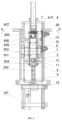
- FIG. 1 is a structure diagram of Embodiment 1;
- FIG. 2 is a left view of FIG. 1 ;
- FIG. 3 is an A-A view in FIG. 2 ;
- FIG. 4 is a B-B view in FIG. 1 ;
- FIG. 5 is a structure diagram of Embodiment 2.
- FIG. 6 is a left view of FIG. 5 ;
- FIG. 7 is a top view of FIG. 6 ;
- FIG. 8 is a C-C view in FIG. 6 ;
- FIG. 9 is a structure diagram of the outer housing
- FIG. 10 is a structure diagram of the inner housing
- FIG. 11 is a left view of FIG. 10 ;
- FIG. 12 is a top view of FIG. 11 ;
- FIG. 13 is a structure diagram of the ratchet wheel pawl & iron interlocks and the internal & outer splines in Embodiment 2;
- FIG. 14 is a structure diagram of the emergency locking mechanism.
- a device for preventing mistakenly stepping on an accelerator by converting acceleration into braking comprising an accelerator push rod mechanism connected to an accelerator pedal ( 21 ) and a current switch making current to a braking actuator, also comprising an outer housing ( 1 ) mounted on the outside of the front side plate of the cab, in which a worm gear & worm mechanism composed of a worm ( 12 ) and a worm gear ( 11 ) is mounted to drive an inner housing ( 2 ) that can only move axially; the other end of the worm ( 12 ) is mounted in an inner housing through a washer ( 27 ) and a worm shaft circlip ( 24 ) by axial limiting; the worm gear ( 11 ) is mounted on a worm gear shaft through flat keys, and is mounted on the inner housing ( 2 ) through a pinion coupled with the worm gear; a rack ( 19 ) coordinating with the worm gear ( 11 ) through a pinion
- one end of the lever connecting fork ( 18 ) is a fork head, and the lower fork edge of the fork head can extend and is provided with a hole for hinging with the accelerator connecting rod or the accelerator cable to increase or decrease the stroke of the accelerator connecting rod or the accelerator cable;
- the other end is a hub, whose center is an axle hole, and extension bars with different angles to the fork, different lengths and a hinge hole can be provided from the hub to meet the various vehicles' different needs for long or short stroke of the accelerator connecting rod or accelerator cable in a push or pull direction, without need to change the designed strokes of the upper, middle and lower push rods.
- the designed stroke of the upper/middle/push rod should be lengthened as far as possible, so as to obtain the minimum ratio of the operating response stroke of the ratchet wheel & pawl mechanism driven by the worm gear & worm mechanism to the designed stroke of the upper/middle/lower push rod; when emergency braking is required for mistakenly stepping on the accelerator, the accelerator opening increase during the operating response stroke period of the ratchet wheel & pawl mechanism is minimized by changing the position of the hinge hole on the rod of the lever connecting fork ( 18 ).
- the stepping force & speed and acceleration cannot trigger jointing of pawls ( 302 ) and the ratchet wheel ( 13 ), and the downward force on the upper push rod ( 7 ) is transferred to the inner housing ( 2 ) and the lower push rod ( 9 ) through the middle push rod ( 8 ) and the worm gear & worm mechanism for going down together, so that the lower push rod ( 9 ) drives an accelerator cable downwards to adjust accelerator opening;
- the stepping force & speed and acceleration make the centrifugal disc ( 10 ) connected to the worm ( 12 ) rotate at a high speed, triggering the jointing of the pawls ( 302 ) and the ratchet wheel ( 13 ) so that the middle push rod ( 8 ) is driven to rotate, further triggering the push rod connecting mechanism ( 5 ) to operate so that the lower push rod ( 9 ) first extends into the accommodating hole ( 503 ) of the central
- the push rod connecting mechanism ( 5 ) comprises a raised inner spline in the lower part of the central hole of the middle push rod ( 8 ); the inner spline divides the central hole of the middle push rod ( 8 ) into a locating hole ( 504 ) for the lower push rod and an ascending return accommodating hole ( 503 ) for the lower push rod; the upper part of the lower push rod ( 9 ) is mounted in the locating hole ( 504 ) and provided with an outer spline that can coordinate with the inner spline; the width of inner spline grooves should be greater than that of outer spline keys, and the greater part is the rotation angle required for the middle push rod ( 8 ) to trigger the current switch;
- the sunken part of the inner spline is a pair of fan-shaped inner spline grooves ( 501 ) that are arranged symmetrically; the raised part of the outer spline is a pair of long and narrow fan-shaped outer spline keys ( 502 );
- the push rod linkage ( 4 ) comprises a rod head ( 401 ) with a U-shaped notch ( 415 ) arranged on the upper end and a splicing sleeve ( 402 ) arranged on the upper part of the middle push rod ( 8 ) for coordinating with the rod head ( 401 ); the inner diameter of the splicing sleeve ( 402 ) on the middle push rod ( 8 ) is greater than the diameter of the central hole, forming a retaining shoulder ( 403 ); the bottom of the rod head ( 401 ) contacts with the face of the retaining shoulder ( 403 ); the lower end of the upper push rod ( 7 ) is hinged in the U-shaped notch ( 415 ) through a large hinge pin ( 404 ), and the upper end of the upper push rod ( 7 ) is connected to the accelerator pedal ( 21 ) by radial limiting; the bottom of the rod head ( 401 ) is provided with a torsion spring mounting shaft ( 405 ) coaxial
- the other end of the middle push rod return torsion spring ( 406 ) is mounted on the wall of the central hole of the middle push rod ( 8 ), and a guide slot can be arranged vertically upwards in the inner wall mounting hole position of the center hole of the middle push rod ( 8 ).
- the current switch comprises a switch anode stator ( 26 ), which is insulated from the outer housing ( 1 ), and a switch cathode rotor ( 20 ), which is arranged on the upper part of the outer edge of the middle push rod ( 8 ), can coordinate with the switch anode stator ( 26 ) for switching on and is used for making current to the braking actuator; the length of the switch anode stator ( 26 ) is greater than the axial stroke of the middle push rod ( 8 ); one side of the middle part of the middle push rod clamped by the open slots ( 407 ) is provided with two screw holes for mounting the switch cathode rotor ( 20 ).
- the pawl & iron interlock ( 3 ) is composed of an iron ( 301 ) and a pawl ( 302 ); the pawl ( 302 ) is provided with a mounting hole matched with the vertical shaft ( 14 ); the pawl ( 302 ) is a 3 ⁇ 8 mm thick V-shaped claw (4 mm thick V-shaped claw in the embodiment); the end far away from the tip of the pawl ( 302 ) is the iron ( 301 ) unified with the pawl ( 302 ); the iron ( 301 ) is a half-cut waist-shaped block protruding from the upper plane of the pawl ( 302 ); the thickness of the half-cut waist-shaped block is two to three times of the thickness of the pawl ( 302 ) (in the embodiment, the thickness of the half-cut waist-shaped block is two times of the thickness of the pawl ( 302 )); the pawl ( 302 ) achieves locating through a bumping post (
- the switch anode stator ( 26 ) is to arrange two anchor screws on one side of a long and narrow copper sheet; the copper sheet and screws must be insulated from the outer housing ( 1 ) except for the side in contact with the switch cathode rotor ( 20 ).
- the switch cathode rotor ( 20 ) is folded by a copper sheet and has two mounting holes.
- a method for preventing mistakenly stepping on an accelerator by converting acceleration into braking makes use of the accelerator pedal ( 21 ) stepping force & speed and acceleration to trigger the device for preventing mistakenly stepping on an accelerator by converting acceleration into braking, which comprises an accelerator push rod mechanism connected to an accelerator pedal ( 21 ) and a current switch making current to a braking actuator, and also comprises an outer housing ( 1 ) in which a worm gear & worm mechanism composed of a worm ( 12 ) and a worm gear ( 11 ) is mounted to drive an inner housing ( 2 ) that can only move axially; the worm ( 12 ) is mounted in the inner housing ( 2 ) by axial limiting, and the worm gear ( 11 ) is mounted on the inner housing ( 2 ); a rack ( 19 ) coordinating with the worm gear ( 11 ) through a pinion coupled with the worm gear is fixedly mounted on the outer housing ( 1 ); the accelerator push rod mechanism comprises an upper push rod ( 7 ), a middle push rod
- the stepping force & speed and acceleration cannot trigger jointing of pawls ( 302 ) and the ratchet ( 13 ); the downward force on the upper push rod ( 7 ) is transferred to the inner housing ( 2 ) and the lower push rod ( 9 ) through the middle push rod ( 8 ) and the worm gear & worm mechanism for going down together; the pinion coupled with the worm gear on the inner housing ( 2 ) engages with the rack ( 19 ) on the outer housing ( 1 ) for moving downwards to make the worm ( 12 ) rotate at a low speed, and simultaneously the downward force on the middle push rod ( 8 ) is transferred to the lower push rod ( 9 ) for moving downwards and pushing the lever connecting fork ( 18 ) to drive the accelerator cable connected to adjust accelerator opening; when mistakenly stepping on the accelerator in an emergency, the stepping force & speed and acceleration make the centrifugal disc ( 10 ) connected to the worm ( 12 )
- the fork edge of the stroke switch should be long and narrow to adapt to the need of the middle push rod ( 8 ) to move up and down; when the middle push rod ( 8 ) is rotating, the fork on the stroke switch will be pushed to close so as to connect the circuit; when the middle push rod ( 8 ) returns, the fork will be driven to disconnect the circuit, so as to realize the conversion of acceleration into braking and thus prevent safety accidents caused by mistakenly stepping on the accelerator; the accelerator pedal ( 21 ) is released; as the lower end of the middle push rod ( 8 ) is fitted with shaft circlip for axial limiting with the worm ( 12 ); under the action of the spring in the same position with the accelerator pedal ( 21 ), the device returns to the state that the engine is idle.
- the worm gear & worm mechanism rotating ratio, the iron mass and the pawl return torsion spring torque are also used to distinguish the stepping force & speed and acceleration when urgently stepping on the accelerator for overtaking and that when mistakenly stepping on the accelerator for coarse acceleration, and after setting the values of the worm gear & worm mechanism rotating ratio, the iron mass and the pawl return torsion spring torque, adopting the pedal stepping force & speed and acceleration dual triggering mode can ensure that the three working conditions have clear and large intervals which neither overlap nor disturb each other.
- a device for preventing mistakenly stepping on an accelerator by converting acceleration into braking comprising an accelerator push rod mechanism connected to an accelerator pedal ( 21 ) and a current switch making current to a braking actuator, makes use of the accelerator pedal ( 21 ) stepping force & speed and acceleration to trigger the conversion of acceleration into braking, and also comprises an outer housing ( 1 ) mounted on the outside of the front side plate of the cab; a worm gear & worm mechanism composed of a worm ( 12 ) and a worm gear ( 11 ) is mounted in the outer housing ( 1 ) to drive an inner housing ( 2 ) that can only move axially; the other end of the worm ( 12 ) is mounted in the inner housing ( 2 ) through the washer ( 27 ) and the worm shaft circlip ( 24 ) by axial limiting; the worm gear ( 11 ) is mounted on the pinion coupled with the worm gear through flat keys; the worm gear ( 11 ) is mounted on the inner
- the push rod connecting mechanism ( 5 ) comprises a raised inner spline in the lower part of the central hole of the middle push rod ( 8 ); the inner spline divides the central hole of the middle push rod ( 8 ) into a locating hole ( 504 ) for the lower push rod and an ascending return accommodating hole ( 503 ) for the lower push rod; the upper part of the lower push rod ( 9 ) is mounted in the locating hole ( 504 ) and provided with an outer spline that can coordinate with the inner spline; the width of inner spline grooves should be greater than that of outer spline keys, and the greater part is the rotation angle required for the middle push rod ( 8 ) to trigger the current switch;
- the sunken part of the inner spline is a pair of fan-shaped inner spline grooves ( 501 ) that are arranged symmetrically; the raised part of the outer spline is a pair of long and narrow fan-shaped outer spline keys ( 502 );
- the push rod linkage ( 4 ) comprises a rod head ( 401 ) with a U-shaped notch ( 415 ) arranged on the upper end and a splicing sleeve ( 402 ) arranged on the upper part of the middle push rod ( 8 ) for coordinating with the rod head ( 401 ); the inner diameter of the splicing sleeve ( 402 ) on the middle push rod ( 8 ) is greater than the diameter of the central hole, forming a retaining shoulder ( 403 ); the bottom of the rod head ( 401 ) contacts with the face of the retaining shoulder ( 403 ); the lower end of the upper push rod ( 7 ) is hinged in the U-shaped notch ( 415 ) through a large hinge pin ( 404 ), and the upper end of the upper push rod ( 7 ) is connected to the accelerator pedal ( 21 ) by radial limiting; the bottom of the rod head ( 401 ) is provided with a torsion spring mounting shaft ( 4
- the other end of the middle push rod return torsion spring ( 406 ) is mounted on the wall of the central hole of the middle push rod ( 8 ), and a guide slot can be arranged vertically upwards in the inner wall mounting hole position of the center hole of the middle push rod ( 8 ).
- the setting method of the above stop pin is to drill a hole with a diameter (5 mm in the embodiment) greater than the greater than the internal annular groove ( 413 ) height (4.1 mm in the embodiment) on the outer edge of the setting position of the splicing sleeve ( 402 ), mount the short cylinder into the hole by interference fit, perform spot welding on the outer edge, and finally process the two end faces of the short cylinder to be consistent with the inner and outer round faces (in this position) of the splicing sleeve ( 402 ).
- the current switch comprises a switch anode stator ( 26 ), which is insulated from the outer housing ( 1 ), and a switch cathode rotor ( 20 ), which is arranged on the upper part of the outer edge of the middle push rod ( 8 ), can coordinate with the switch anode stator ( 26 ) for switching on and is used for making current to the braking actuator; the length of the switch anode stator ( 26 ) is greater than the axial stroke of the middle push rod ( 8 ); the outer edge of the splicing sleeve ( 402 ) on the middle push rod ( 8 ) is provided with two screw holes for mounting the switch cathode rotor ( 20 ).
- the emergency locking mechanism ( 6 ) for recognition of normally stepping on the accelerator, urgently stepping on the accelerator for overtaking and mistakenly stepping on the accelerator, the emergency locking mechanism ( 6 ) comprises circular arc ring grooves ( 601 ) arranged uniformly on the wall of the axial through hole of the worm ( 12 ) along the axial direction and U-shaped recesses ( 603 ) arranged uniformly in the middle part of the outer edge of the middle push rod ( 8 ) along the radial direction for coordinating with the circular arc ring grooves ( 601 ), and vertical U shapes are under oblique U shapes on the U-shaped recesses ( 603 ) In which steel balls ( 602 ) are mounted.
- the upper part of the outer housing ( 1 ) is a whole-circle pipe; the upper part of the whole-circle pipe is provided with an outer housing notch ( 101 ) required for not hindering the full-stroke movement and rotation of the switch cathode rotor ( 20 ) on the middle push rod ( 8 ); the middle part of the outer housing is a semicircle pipe; the radius of the lower part of the semicircle pipe is consistent with the radius (in the full length direction) of the semicircle pipe of the outer housing ( 1 ) according to Embodiment 1, and the difference is that the radius of the lower part greater than is that of the upper part of the semicircle pipe for mounting the urgent acceleration judging spring ( 22 ); the lower end of the semicircle pipe is provided with a fixed large semicircle tile ( 103 ); the opposite side of the fixed large semicircle tile ( 103 ) is provided with a removable small semicircle tile ( 102 ); the inner diameter of the fixed large semicircle tile ( 103 ) and that
- the inner housing ( 2 ) is a circular pipe body; the middle section of the inner wall of the circular pipe body is provided with two internal annular protruding shoulders ( 201 ) for axial limiting of the worm ( 12 ); the middle section of the outer edge of the circular pipe body is provided with an external annular protruding shoulder ( 202 ) with a radius inconsistent with the full-length radius of the inner housing ( 2 ) in Embodiment 1 but with a difference that it is used for mounting the urgent acceleration judging spring ( 22 ), and both sides of the middle section of the outer edge of the circular pipe body are provided with two external shaft seats ( 203 ) for mounting the worm gear ( 11 ); bearings ( 204 ) are mounted in the external shaft seats ( 203 ); the pipe body between two external shaft seats ( 203 ) is provided with a rectangular notch ( 205 ) required for the engaging of the worm gear ( 11 ) and the worm ( 12 ); the upper part of the circular pipe body is provided with an inner housing notch ( 206
- the method for mounting the inner housing ( 2 ) and the urgent acceleration judging spring ( 22 ) The inner housing ( 2 ) is loaded in the outer housing ( 1 ) from the small semicircle notch in the lower part of the outer housing ( 1 ) and then pushed to the uppermost position; the urgent acceleration judging spring ( 22 ) is compressed by a special tool and then loaded from the semicircle notch, and the protecting cover on the top of the outer housing presses the inner housing to the normal position.
- a method for preventing mistakenly stepping on an accelerator by converting acceleration into braking makes use of the accelerator pedal ( 21 ) stepping force & speed and acceleration to trigger the device for preventing mistakenly stepping on an accelerator by converting acceleration into braking, which comprises an accelerator push rod mechanism connected to an accelerator pedal ( 21 ) and a current switch making current to a braking actuator, and also comprises an outer housing ( 1 ) in which a worm gear & worm mechanism composed of a worm ( 12 ) and a worm gear ( 11 ) is mounted to drive an inner housing ( 2 ) that can only move axially; the worm ( 12 ) is mounted in the inner housing ( 2 ) by axial limiting, and the worm gear ( 11 ) is mounted on the inner housing ( 2 ); a rack ( 19 ) coordinating with the worm gear ( 11 ) through a pinion coupled with the worm gear is fixedly mounted on the outer housing ( 1 ); the accelerator push rod mechanism comprises an upper push rod ( 7 ), a middle push rod
- the urgent acceleration judging spring ( 22 ) is used to distinguish the stepping force & speed and acceleration when stepping on the accelerator during normal driving and that when stepping on the accelerator for overtaking; the urgent acceleration judging spring force, the worm gear & worm mechanism rotating ratio, the iron mass ( 301 ) and the pawl return torsion spring ( 17 ) torque are also used to distinguish the stepping force & speed and acceleration when urgently stepping on the accelerator for overtaking and that when mistakenly stepping on the accelerator for coarse acceleration, and after setting the urgent acceleration judging spring force ( 22 ), the worm gear & worm mechanism rotating ratio, the iron mass ( 301 ) and the pawl return torsion spring torque, adopting the pedal stepping force & speed and acceleration dual triggering mode can ensure that the three working conditions have clear and large intervals which neither overlap nor disturb each other.
- the elasticity of the urgent acceleration judging spring ( 22 ) is 80 ⁇ 160 N, not only being able to overcome the friction on the worm ( 12 ) from the middle push rod ( 8 ) but also overcome the gravity of the inner housing ( 2 ) and the worm gear & worm mechanism on the inner housing so as to ensure no downward moving during acceleration for normal driving, but also being able to avoid too much resistance on the foot when the emergency locking mechanism 6 operates due to acceleration for overtaking;
- the accelerator pedal stepping force to make the pawls operate is greater than 300 N, and the acceleration (a) is higher than 30 m/S2.
- the embodiment adopts the pedal stepping force & speed and acceleration dual triggering mode, to meet the need for recognition of normally stepping on the accelerator, urgently stepping on the accelerator for overtaking and mistakenly stepping on the accelerator.
- a driver normally steps on accelerator during driving, due to the low downward force on the upper push rod ( 7 ), both speed and acceleration are not high, and the emergency locking mechanism ( 6 ) does not operate; the low downward is not transferred to the worm ( 12 ) but only transferred to the lower push rod ( 9 ); as the resistance of the urgent acceleration judging spring ( 22 ) results in that neither the worm gear & worm mechanism nor the inner housing ( 2 ) move, the upper push rod ( 7 ), the middle push rod ( 8 ) and the lower push rod ( 9 ) are linked to go down and push the lever connecting fork ( 18 ) to drive the accelerator cable connected to it for adjusting the accelerator opening.
- the middle push rod ( 8 ) locks the worm ( 12 ) through the steel balls ( 602 ); the emergency locking mechanism ( 6 ) operates; the middle push rod ( 8 ) pushes the worm gear ( 11 ) to rapidly go down through the worm ( 12 ) and the inner housing ( 2 ); the centrifugal disc ( 10 ) on the worm ( 12 ) rotates at a high speed so as to drive the irons ( 301 ) and trigger the jointing of the pawls ( 302 ) and the long and narrow ratchet wheel ( 25 ); the pawls ( 302 ) engages with the ratchets on the middle push rod ( 8 ) so as to make the middle push rod ( 8 ) following the worm ( 12 ) to rotate; after the middle push rod ( 8 ) rotates at a certain angle, the long and narrow fan-shaped spline keys ( 502 ) on the lower push rod ( 9 ) that cannot rotate
- the fork edge of the stroke switch should be long and narrow to adapt to the need of the middle push rod ( 8 ) to move up and down; when the middle push rod ( 8 ) is rotating, the fork on the stroke switch will be pushed to close so as to connect the circuit; when the middle push rod ( 8 ) returns, the fork will be driven to disconnect the circuit, so as to realize the conversion of acceleration into braking and thus prevent safety accidents caused by mistakenly stepping on the accelerator; the accelerator pedal ( 21 ) is released; the upper push rod ( 7 ) and the middle push rod ( 8 ) return under the action of the accelerator pedal ( 21 ) return ring; the inner housing ( 2 ) and the worm gear & worm mechanism return through upward pushing by the urgent acceleration judging spring ( 22 ), and the lower push rod ( 9 ) is driven back to the state that the engine is idle by the return tension spring of the lever connecting fork ( 18 ).
- the two steel balls ( 602 ) should be placed in the left and right oblique positions rather than the front and back positions, so as not to affect the falling speed of the steel balls ( 602 ).
- the protecting cover on the top of the outer housing ( 1 ) is provided with corrugated rubber hose for dust prevention.
Landscapes
- Engineering & Computer Science (AREA)
- Transportation (AREA)
- Mechanical Engineering (AREA)
- Chemical & Material Sciences (AREA)
- Combustion & Propulsion (AREA)
- Mechanical Control Devices (AREA)
- Auxiliary Drives, Propulsion Controls, And Safety Devices (AREA)
- Braking Elements And Transmission Devices (AREA)
Abstract
Description
-
- Where: 1—outer housing, 101—outer housing notch, 102—removable small semicircle tile, 103—fixed large semicircle tile, 104—protecting crust, 105—rack mounting hole, 106—switch anode stator mounting hole, 107—sliding shaft support;
- 2—inner housing, 201—internal annular protruding shoulder, 202—external annular protruding shoulder, 203—external shaft seat, 204—bearing, 205—rectangular notch; 206—inner housing notch
- 3—pawl & iron interlock, 301—iron, 302—pawl, 303—bumping post;
- 4—push rod linkage, 401—rod head, 402—splicing sleeve, 403—retaining shoulder, 404—large hinge pin, 405—torsion spring mounting shaft, 406—middle push rod return torsion spring, 407—open slot, 408—special-shaped snap ring, 409—external annular groove, 410—stop block; 411—small hinge pin, 412—stop pin, 413—internal annular groove, 414—technological notch, 415—U-shaped notch;
- 5—push rod connecting mechanism, 501—fan-shaped inner spline groove, 502—fan-shaped outer spline key, 503—accommodating hole, 504—locating hole;
- 6—emergency locking mechanism, 601—circular arc ring groove, 602—steel ball, 603—U-shaped recess;
- 7—upper push rod, 8—middle push rod, 9—lower push rod, 10—centrifugal disc, 11—worm gear, 12—worm, 13—ratchet wheel, 14—vertical shaft, 15—sliding shaft, 16—slide, 17 return torsion spring, 18—lever connecting fork, 19—rack, 20—switch cathode rotor, 21—accelerator pedal, 22—urgent acceleration judging spring, 24—worm shaft circlip, 25—long and narrow ratchet wheel, 26—switch anode stator, 27—washer.
Claims (10)
Applications Claiming Priority (3)
| Application Number | Priority Date | Filing Date | Title |
|---|---|---|---|
| CN202010770598.8 | 2020-08-04 | ||
| CN202010770598.8A CN111806228B (en) | 2020-08-04 | 2020-08-04 | Device and method for preventing mistaken stepping on accelerator and oiling conversion braking |
| PCT/CN2021/110000 WO2022028355A1 (en) | 2020-08-04 | 2021-08-02 | Device and method for preventing mistakenly stepping on accelerator by converting refueling into braking |
Publications (2)
| Publication Number | Publication Date |
|---|---|
| US20230249547A1 US20230249547A1 (en) | 2023-08-10 |
| US12214660B2 true US12214660B2 (en) | 2025-02-04 |
Family
ID=72863571
Family Applications (1)
| Application Number | Title | Priority Date | Filing Date |
|---|---|---|---|
| US17/928,203 Active 2041-08-19 US12214660B2 (en) | 2020-08-04 | 2021-08-02 | Device and method for preventing mistakenly stepping on an accelerator by converting acceleration into braking |
Country Status (5)
| Country | Link |
|---|---|
| US (1) | US12214660B2 (en) |
| JP (1) | JP2023534782A (en) |
| CN (1) | CN111806228B (en) |
| DE (1) | DE112021001758T5 (en) |
| WO (1) | WO2022028355A1 (en) |
Families Citing this family (1)
| Publication number | Priority date | Publication date | Assignee | Title |
|---|---|---|---|---|
| CN111806228B (en) | 2020-08-04 | 2023-06-02 | 刘志光 | Device and method for preventing mistaken stepping on accelerator and oiling conversion braking |
Citations (10)
| Publication number | Priority date | Publication date | Assignee | Title |
|---|---|---|---|---|
| DE2339529A1 (en) | 1973-08-03 | 1975-02-13 | Ardie Werk Gmbh | Accelerator linkage for heavy vehicle with fuel injection pump - has hydraulic servo to alter linkage length when changing gear |
| CN2229893Y (en) * | 1995-07-18 | 1996-06-26 | 李扬荣 | Device for automatically controlling vehicle speed, operated by accelerator pedal |
| JP2003146106A (en) | 2001-11-14 | 2003-05-21 | Jisaku Mayuzumi | Emergency stopping device for vehicle |
| US20070068321A1 (en) * | 2005-08-25 | 2007-03-29 | Korea Automotive Technology Institute | Adjustable pedal assembly |
| CN102225691A (en) | 2011-04-19 | 2011-10-26 | 东华大学 | A kind of anti-misstepping brake device of automobile accelerator |
| CN106274484A (en) | 2016-08-30 | 2017-01-04 | 李博远 | A kind of gas intelligent error preventing steps on brake gear |
| CN109591884A (en) * | 2018-11-30 | 2019-04-09 | 上海亿博机电设备有限公司 | A kind of automatically controlled loading machine |
| CN110171294A (en) | 2019-05-28 | 2019-08-27 | 杭州科技职业技术学院 | A kind of emergency brake device of car ACCEL |
| CN111806228A (en) | 2020-08-04 | 2020-10-23 | 刘志光 | Device and method for preventing mistaken stepping on accelerator and refueling conversion braking |
| CN112092616A (en) * | 2020-09-01 | 2020-12-18 | 齐胜利 | Adjustable accelerator-suddenly-stepping brake device |
Family Cites Families (14)
| Publication number | Priority date | Publication date | Assignee | Title |
|---|---|---|---|---|
| JPH07246856A (en) * | 1991-06-28 | 1995-09-26 | Shoji Kobayashi | Accelerator |
| JPH11278092A (en) * | 1998-03-26 | 1999-10-12 | Isuzu Motors Ltd | Automatic transmission vehicle runaway preventive device |
| JP4185296B2 (en) * | 2001-12-28 | 2008-11-26 | 株式会社オートテクニカ | Operation pedal unit for vehicles |
| JP4114010B2 (en) * | 2004-03-26 | 2008-07-09 | マツダ株式会社 | Car movable pedal adjustment device |
| JP4341468B2 (en) * | 2004-05-28 | 2009-10-07 | マツダ株式会社 | Car driving posture adjustment device |
| CN2827801Y (en) * | 2005-10-15 | 2006-10-18 | 尹智彪 | Vehicle emergency brake mechanism |
| CN200999006Y (en) * | 2007-01-10 | 2008-01-02 | 毛嘉 | Automobile accelerator miss-proof control device |
| CN100999185A (en) * | 2007-01-10 | 2007-07-18 | 毛嘉 | Control device for proventing motor vehicle throttle disorder |
| CN201201590Y (en) * | 2008-04-15 | 2009-03-04 | 尚雯雯 | Mechanical protecting device for preventing pressing accelerator pedal mistakenly in case of automobile emergency braking |
| JP5335049B2 (en) * | 2011-10-04 | 2013-11-06 | 株式会社ツタ | Accelerator pedal misoperation prevention device |
| CN102874241B (en) * | 2012-11-05 | 2015-01-14 | 安徽工业大学 | Emergency braking mis-operation preventing device |
| CN202863152U (en) * | 2012-11-05 | 2013-04-10 | 安徽工业大学 | Emergency braking anti-misoperation device |
| DE102014217319A1 (en) * | 2014-08-29 | 2016-03-03 | Robert Bosch Gmbh | Active accelerator pedal with worm gear |
| JP6759091B2 (en) * | 2016-12-22 | 2020-09-23 | 株式会社ミツバ | Reaction force generator |
-
2020
- 2020-08-04 CN CN202010770598.8A patent/CN111806228B/en active Active
-
2021
- 2021-08-02 JP JP2022570362A patent/JP2023534782A/en active Pending
- 2021-08-02 US US17/928,203 patent/US12214660B2/en active Active
- 2021-08-02 WO PCT/CN2021/110000 patent/WO2022028355A1/en active Application Filing
- 2021-08-02 DE DE112021001758.6T patent/DE112021001758T5/en active Pending
Patent Citations (10)
| Publication number | Priority date | Publication date | Assignee | Title |
|---|---|---|---|---|
| DE2339529A1 (en) | 1973-08-03 | 1975-02-13 | Ardie Werk Gmbh | Accelerator linkage for heavy vehicle with fuel injection pump - has hydraulic servo to alter linkage length when changing gear |
| CN2229893Y (en) * | 1995-07-18 | 1996-06-26 | 李扬荣 | Device for automatically controlling vehicle speed, operated by accelerator pedal |
| JP2003146106A (en) | 2001-11-14 | 2003-05-21 | Jisaku Mayuzumi | Emergency stopping device for vehicle |
| US20070068321A1 (en) * | 2005-08-25 | 2007-03-29 | Korea Automotive Technology Institute | Adjustable pedal assembly |
| CN102225691A (en) | 2011-04-19 | 2011-10-26 | 东华大学 | A kind of anti-misstepping brake device of automobile accelerator |
| CN106274484A (en) | 2016-08-30 | 2017-01-04 | 李博远 | A kind of gas intelligent error preventing steps on brake gear |
| CN109591884A (en) * | 2018-11-30 | 2019-04-09 | 上海亿博机电设备有限公司 | A kind of automatically controlled loading machine |
| CN110171294A (en) | 2019-05-28 | 2019-08-27 | 杭州科技职业技术学院 | A kind of emergency brake device of car ACCEL |
| CN111806228A (en) | 2020-08-04 | 2020-10-23 | 刘志光 | Device and method for preventing mistaken stepping on accelerator and refueling conversion braking |
| CN112092616A (en) * | 2020-09-01 | 2020-12-18 | 齐胜利 | Adjustable accelerator-suddenly-stepping brake device |
Also Published As
| Publication number | Publication date |
|---|---|
| CN111806228A (en) | 2020-10-23 |
| CN111806228B (en) | 2023-06-02 |
| US20230249547A1 (en) | 2023-08-10 |
| DE112021001758T5 (en) | 2023-03-02 |
| WO2022028355A1 (en) | 2022-02-10 |
| JP2023534782A (en) | 2023-08-14 |
Similar Documents
| Publication | Publication Date | Title |
|---|---|---|
| EP4086485B1 (en) | Mechanical unlocking mechanism for electronic parking | |
| US12214660B2 (en) | Device and method for preventing mistakenly stepping on an accelerator by converting acceleration into braking | |
| CN105584364B (en) | A kind of mechanical centrifugal formula vehicle accelerator anti-false step safety aid | |
| CN103994208B (en) | A kind of Vehicular multifunctional handle type block selecting device | |
| CN110001397B (en) | Anti-misstep safety device for automobile accelerator pedal and operation method thereof | |
| EP0340814B1 (en) | Anti-lock brake device for vehicles | |
| US6186263B1 (en) | Four-wheeled all-terrain vehicle and speed change apparatus used for the same | |
| CN111806227A (en) | Improved automobile pedal device | |
| CN111469970B (en) | Electric bicycle chain wheel clutch driving method | |
| CN111546888A (en) | Automobile accelerator pedal with locking mechanism | |
| CN214888804U (en) | An electronic wire-controlled parking device and automobile | |
| KR20070045318A (en) | Motorized lock | |
| CN111959270B (en) | A kind of protective device for accelerator pedal and using method thereof | |
| CN112268106A (en) | Knob assembly of shifting | |
| CN209813726U (en) | Electronic accelerator pedal assembly | |
| CN218759292U (en) | Safety door lock | |
| CN209776177U (en) | electronic accelerator pedal assembly | |
| CN213184086U (en) | Lifting detection mechanism for knob switch | |
| CN214083863U (en) | Braking device for accelerator pedal protective device | |
| CN214984825U (en) | A device for preventing accidental stepping of automobile accelerator using ratchet | |
| CN213691847U (en) | Knob switch for automatic transmission vehicle | |
| CN210653054U (en) | Parking operation device with interlocking effect | |
| CN213184074U (en) | Locking mechanism is prevented touching by mistake by knob switch | |
| KR970004800Y1 (en) | Roller support part of emergency release device of automatic transmission | |
| JP2506561Y2 (en) | Automatic transmission parking equipment |
Legal Events
| Date | Code | Title | Description |
|---|---|---|---|
| FEPP | Fee payment procedure |
Free format text: ENTITY STATUS SET TO UNDISCOUNTED (ORIGINAL EVENT CODE: BIG.); ENTITY STATUS OF PATENT OWNER: MICROENTITY |
|
| FEPP | Fee payment procedure |
Free format text: ENTITY STATUS SET TO SMALL (ORIGINAL EVENT CODE: SMAL); ENTITY STATUS OF PATENT OWNER: MICROENTITY |
|
| FEPP | Fee payment procedure |
Free format text: ENTITY STATUS SET TO MICRO (ORIGINAL EVENT CODE: MICR); ENTITY STATUS OF PATENT OWNER: MICROENTITY |
|
| STPP | Information on status: patent application and granting procedure in general |
Free format text: DOCKETED NEW CASE - READY FOR EXAMINATION |
|
| STPP | Information on status: patent application and granting procedure in general |
Free format text: NON FINAL ACTION MAILED |
|
| STPP | Information on status: patent application and granting procedure in general |
Free format text: RESPONSE TO NON-FINAL OFFICE ACTION ENTERED AND FORWARDED TO EXAMINER |
|
| STPP | Information on status: patent application and granting procedure in general |
Free format text: FINAL REJECTION MAILED |
|
| STPP | Information on status: patent application and granting procedure in general |
Free format text: RESPONSE AFTER FINAL ACTION FORWARDED TO EXAMINER |
|
| STPP | Information on status: patent application and granting procedure in general |
Free format text: NOTICE OF ALLOWANCE MAILED -- APPLICATION RECEIVED IN OFFICE OF PUBLICATIONS |
|
| ZAAB | Notice of allowance mailed |
Free format text: ORIGINAL CODE: MN/=. |
|
| STPP | Information on status: patent application and granting procedure in general |
Free format text: PUBLICATIONS -- ISSUE FEE PAYMENT RECEIVED |
|
| STPP | Information on status: patent application and granting procedure in general |
Free format text: PUBLICATIONS -- ISSUE FEE PAYMENT VERIFIED |
|
| STCF | Information on status: patent grant |
Free format text: PATENTED CASE |