US1221218A - Floor-scrubber. - Google Patents
Floor-scrubber. Download PDFInfo
- Publication number
- US1221218A US1221218A US86387914A US1914863879A US1221218A US 1221218 A US1221218 A US 1221218A US 86387914 A US86387914 A US 86387914A US 1914863879 A US1914863879 A US 1914863879A US 1221218 A US1221218 A US 1221218A
- Authority
- US
- United States
- Prior art keywords
- scrubber
- scrubbing
- floor
- compartment
- base
- Prior art date
- Legal status (The legal status is an assumption and is not a legal conclusion. Google has not performed a legal analysis and makes no representation as to the accuracy of the status listed.)
- Expired - Lifetime
Links
Images


Classifications
-
- A—HUMAN NECESSITIES
- A47—FURNITURE; DOMESTIC ARTICLES OR APPLIANCES; COFFEE MILLS; SPICE MILLS; SUCTION CLEANERS IN GENERAL
- A47L—DOMESTIC WASHING OR CLEANING; SUCTION CLEANERS IN GENERAL
- A47L1/00—Cleaning windows
- A47L1/06—Hand implements
- A47L1/08—Hand implements with provision for supplying liquids, e.g. cleaning agents
Definitions
- This invention relates to improvements in fountain floor scrubbers and one of its 9bjects is the provision of a device of this klnd which shall include a fabric floor engaging or scrubbing member, on a plate of suflicient weight to hold said member 1n effective scrubbing contact with the floor.
- a further object of this lnvention 1 s the provision of a fountain floor scrubber, wherein the plate shall be constructed so as to distribute a suitable fluid to the scrubbmg member and to take up any excess fluid from the member, so as to prevent its over saturation, whereby just suflicient fluid Wlll be applied to the floor to effect a thorough scrubbing thereof.
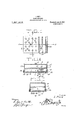
- Fig.2 is a top plan view of the scrubber.
- Fig. 3 is a bottom plan view of the scrubber.
- Fig. 4 is a cross sectional view on the line 4-4 of Fig. 3. 0
- Fig. 5 is a cross sectional view on the line 55 of Fig. 3, and
- Fig. 6 is a detail view partially in section of the handle.
- ings, 1 designates the body portion of the scrubber as an entirety, which body portion is formed of a rectangular shaped tank,
- the body portion 1 of the scrubber has a part1- operation.
- tipn 2 formed horizontally therein, which dlvides the body portion into u per and lower compartments 3 and 4.
- he upper compartment 3 has fluid tight joints, so as to prevent the leakage of liquid therefrom, and 1t forms a liquid retaining chamber for holding water for scrubbing.
- the upper side 5 of the body portion 1 has an inlet opening for the introduction of water or other scrubbing liquid into the chamber 3 and an ordlnary type of closure cap 6 to close said opening.
- the lower section or compartment 4 of the bodv portion 1 has an enlarged or extra thickened base 7, which is secured tothe body portion in any suitable manner and which has flexible binding strips 8 positioned about the outercircumference of the same to prevent the leakage of water or liquid thereoutof.
- the base 7 is v provided with a plurality of perforations 9 formed therein, which perforations extend across substantially one half of the base to allow the cloth under one-half of the base to absorb the dirty water or excess water during the scrubbing
- the other half of the base 7 has a plurality of slots 10 formed therein, which slots extend substantially the entire width of the-base.
- a thin sheet of metal 11 is positioned inwardly of the slotted portion of the base 7 and it 1s provided with a pluralityof perforations 12, which aline with the slots 10 so as to permit liquid to flow through the openings and the slots and through the openings 10 formed in the fabric scrubbing cloth 13 which is detachablv secured to the base of the scrubber, the sheet of metal 11 being so positioned above the fabric scrubbing cloth as to leave a space between the two so as to permit the scrubbing fluid to flow to the cloth more easily and allow the scrubbing cloth to become more fluid.
- the bottom compartment 4' contains a partition 14 extending upwardly from the base 7 between the slots 10 and the perforations 9 dividing the compartment 4 into two separate compartments, a dispe compartment 17 for retaining the liquid prior to the same flowing through the openmgs 12 and the slots 10 into the fabric floor engaging member 13, and the compartment 18 which is provided with perforations'9 thereby allowing the scrubbing member or cloth 13 under the compartment 18' to absorb the excess fluid andforce it into said compartment.
- the partition 2 which divides the body portion 1 into the compartments 3 and 4-. has an outlet valve 15 connected thereto, the opening or closing of which valve is controlled by the rocking of a rod 16.
- the rod 16 extends transversely through the compartment 4 and out of one end of the body portion 1, having its outwardly extending or protruding'end 17 bent upwardly to facilitate the engagement of the same by the fingers of a person for operating the valve 15 to permit cutting off the flow of the liquid from the compartment 3 into the compartment formed by the partition 14.
- the body portion l has a bail 18 pivotally connected thereto, which bail has a handle 19 secured. thereto by angled supporting braces 19 and 20.
- the angled supporting braces 19 and 20 are deta-chably secured to the vertex of the bail 18 by thumb screws 21, so that the handle may be removed fromv attachment to the scrubber if it is so desired, for changing different handles for regulating the length of 'the handle to accommodate persons of different heights.
- the cloth 13 which is secured to the under surface of the base 7 is provided with a plurality of perforations 10' formed therethrough, which perforations are adjusted for ahrison with the slots 10 and the openings 12 to permit the liquid to pass through the cloth upon the floor which is being scrubbed.
- the cloth 13 has a draw string (not shown) secured thereto for securely attaching the cloth to the base 7.
- the scrubbing fluid is poured into the compartment 3 through the inlet opening in the same and the cloth or fabric scrubbing cloth 13 is attached to the under surface of the bottom 7 and securely held thereon by tightening the draw. string.
- the rod 16 is rocked for opening the valve 15 to permit the liquid to flow through the valve into the compartment formed by the partition 14 and out of this compartment through the perforations 12 and the slots 10 into the scrubbing cloth 13 for properly moistening the floor for scrubbing the same.
- a fountain floor scrubber comprising a comparatively heavy plate having compartments formed in the upper side of the plate, the bottom wall of each compartment being perforated, a scrubbing member secured to the under side of the plate, and means for supplying a fluid to one of said compartments, said fluid passing through the perforations of the bottom wall of sald compartment to said'scrubbing member.
- a floor scrubber comprising top, side and end walls, a horizontal partition secured to the side and end walls to form a liquid chamber, a base, vertical flanges formed on the base for receiving the slde and end walls, and said side and end walls resting upon the base, a vertical partition formed on the upper face of the base to form a pair of compartments, said base having a plurality of openings to each compartment, a scrubbing member secured to the base, and a valve secured to the horizontal partition for controlling fluid into one of the compartments.
Landscapes
- Cleaning Implements For Floors, Carpets, Furniture, Walls, And The Like (AREA)
Description
l. REID.
FLOOR SCRUBBER.
APPLICATION FILED szrnzs. m4.
2SHEE' [ETI- I; REID.
FLOOR SCRUBBER'.
APPLICATION m zn SEPT. 28. 19w:
LWLM @h Patented Apr. 3, 1917.
2 SHEETS-SHEET 2- G. E. IVIITTINGER.
THREE PIECE METALLIC SHIPPING BARREL- APPLICATION FILED MAY18| 1920.
Patented Apr. 26, 1921..
3 SHEETS-SHEET 3.
ISAIAH REIJD, 0F
ELIZABETH our, NORTH oaaonrivny.
FLOOR-SCRUBBER- Specification of Letters Patent.
Patented Apr. 3, 191?.
Application filed September 28, 1914. Serial 1W0. 863,679.
To all whom it may concern:
Be it known that I, ISAIAH REID, a citizen of the United States, residing at Elizabeth City, in the county of Pasquotank and State of North Carolina, have invented certain new and useful Improvements in Floor- Scrubbers; and I do hereby declare the following to be a full, clear, and exact description of the invention, such as willenable others skilled in the art to which it appertains to make and use the same.
This invention relates to improvements in fountain floor scrubbers and one of its 9bjects is the provision of a device of this klnd which shall include a fabric floor engaging or scrubbing member, on a plate of suflicient weight to hold said member 1n effective scrubbing contact with the floor.
A further object of this lnvention 1s the provision of a fountain floor scrubber, wherein the plate shall be constructed so as to distribute a suitable fluid to the scrubbmg member and to take up any excess fluid from the member, so as to prevent its over saturation, whereby just suflicient fluid Wlll be applied to the floor to effect a thorough scrubbing thereof.
With the foregoing and other ob ects in view this invention consists in such novel features of construction, combination and arrangement of parts as will be hereinafter more fully described, illustrated 1n the accompanying drawings and-claimed.
In describing the invention in detall reference will be had to the accompanying drawings wherein like characters designate like or corresponding parts throughout theof the imseveral views, and in which Figure 1 is a side elevation proved scrubber.
Fig.2 is a top plan view of the scrubber. Fig. 3 is a bottom plan view of the scrubber.
Fig. 4 is a cross sectional view on the line 4-4 of Fig. 3. 0
Fig. 5 is a cross sectional view on the line 55 of Fig. 3, and
Fig. 6 is a detail view partially in section of the handle.
Referring more particularly to the draw: ings, 1 designates the body portion of the scrubber as an entirety, which body portion is formed of a rectangular shaped tank,
which is constructed of any suitable type of material such as sheet iron or the like. The body portion 1 of the scrubber has a part1- operation.
tipn 2 formed horizontally therein, which dlvides the body portion into u per and lower compartments 3 and 4. he upper compartment 3 has fluid tight joints, so as to prevent the leakage of liquid therefrom, and 1t forms a liquid retaining chamber for holding water for scrubbing. The upper side 5 of the body portion 1 has an inlet opening for the introduction of water or other scrubbing liquid into the chamber 3 and an ordlnary type of closure cap 6 to close said opening.
The lower section or compartment 4 of the bodv portion 1 has an enlarged or extra thickened base 7, which is secured tothe body portion in any suitable manner and which has flexible binding strips 8 positioned about the outercircumference of the same to prevent the leakage of water or liquid thereoutof.
The base 7 is v provided with a plurality of perforations 9 formed therein, which perforations extend across substantially one half of the base to allow the cloth under one-half of the base to absorb the dirty water or excess water during the scrubbing The other half of the base 7, has a plurality of slots 10 formed therein, which slots extend substantially the entire width of the-base. A thin sheet of metal 11 is positioned inwardly of the slotted portion of the base 7 and it 1s provided with a pluralityof perforations 12, which aline with the slots 10 so as to permit liquid to flow through the openings and the slots and through the openings 10 formed in the fabric scrubbing cloth 13 which is detachablv secured to the base of the scrubber, the sheet of metal 11 being so positioned above the fabric scrubbing cloth as to leave a space between the two so as to permit the scrubbing fluid to flow to the cloth more easily and allow the scrubbing cloth to become more fluid.
The bottom compartment 4' contains a partition 14 extending upwardly from the base 7 between the slots 10 and the perforations 9 dividing the compartment 4 into two separate compartments, a dispe compartment 17 for retaining the liquid prior to the same flowing through the openmgs 12 and the slots 10 into the fabric floor engaging member 13, and the compartment 18 which is provided with perforations'9 thereby allowing the scrubbing member or cloth 13 under the compartment 18' to absorb the excess fluid andforce it into said compartment.
The partition 2, which divides the body portion 1 into the compartments 3 and 4-. has an outlet valve 15 connected thereto, the opening or closing of which valve is controlled by the rocking of a rod 16. The rod 16 extends transversely through the compartment 4 and out of one end of the body portion 1, having its outwardly extending or protruding'end 17 bent upwardly to facilitate the engagement of the same by the fingers of a person for operating the valve 15 to permit cutting off the flow of the liquid from the compartment 3 into the compartment formed by the partition 14.
The body portion lhas a bail 18 pivotally connected thereto, which bail has a handle 19 secured. thereto by angled supporting braces 19 and 20. The angled supporting braces 19 and 20 are deta-chably secured to the vertex of the bail 18 by thumb screws 21, so that the handle may be removed fromv attachment to the scrubber if it is so desired, for changing different handles for regulating the length of 'the handle to accommodate persons of different heights.
The cloth 13 which is secured to the under surface of the base 7 is provided with a plurality of perforations 10' formed therethrough, which perforations are adjusted for ahnement with the slots 10 and the openings 12 to permit the liquid to pass through the cloth upon the floor which is being scrubbed. The cloth 13 has a draw string (not shown) secured thereto for securely attaching the cloth to the base 7.
In the operation of the improved scrubber heretofore described: The scrubbing fluid is poured into the compartment 3 through the inlet opening in the same and the cloth or fabric scrubbing cloth 13 is attached to the under surface of the bottom 7 and securely held thereon by tightening the draw. string. After the scrubbing cloth has been properly attached to the base 7, the rod 16 is rocked for opening the valve 15 to permit the liquid to flow through the valve into the compartment formed by the partition 14 and out of this compartment through the perforations 12 and the slots 10 into the scrubbing cloth 13 for properly moistening the floor for scrubbing the same.
As the scrubber is pushed over the floor, the excess fluid is absorbed by the cloth 13 and is forced into the collecting compartment 18 during the scrubbing operation.
What is claimed is 1. A fountain floor scrubber comprising a comparatively heavy plate having compartments formed in the upper side of the plate, the bottom wall of each compartment being perforated, a scrubbing member secured to the under side of the plate, and means for supplying a fluid to one of said compartments, said fluid passing through the perforations of the bottom wall of sald compartment to said'scrubbing member.
2. A floor scrubber comprising top, side and end walls, a horizontal partition secured to the side and end walls to form a liquid chamber, a base, vertical flanges formed on the base for receiving the slde and end walls, and said side and end walls resting upon the base, a vertical partition formed on the upper face of the base to form a pair of compartments, said base having a plurality of openings to each compartment, a scrubbing member secured to the base, and a valve secured to the horizontal partition for controlling fluid into one of the compartments.
In'testimony whereof I affix my signature in presence of two witnesses.
ISAIAH REID.
Witnesses:
E. W. CARR, J. W. MIDGETT.
Priority Applications (1)
| Application Number | Priority Date | Filing Date | Title |
|---|---|---|---|
| US86387914A US1221218A (en) | 1914-09-28 | 1914-09-28 | Floor-scrubber. |
Applications Claiming Priority (1)
| Application Number | Priority Date | Filing Date | Title |
|---|---|---|---|
| US86387914A US1221218A (en) | 1914-09-28 | 1914-09-28 | Floor-scrubber. |
Publications (1)
| Publication Number | Publication Date |
|---|---|
| US1221218A true US1221218A (en) | 1917-04-03 |
Family
ID=3289083
Family Applications (1)
| Application Number | Title | Priority Date | Filing Date |
|---|---|---|---|
| US86387914A Expired - Lifetime US1221218A (en) | 1914-09-28 | 1914-09-28 | Floor-scrubber. |
Country Status (1)
| Country | Link |
|---|---|
| US (1) | US1221218A (en) |
Cited By (2)
| Publication number | Priority date | Publication date | Assignee | Title |
|---|---|---|---|---|
| US2641011A (en) * | 1950-08-02 | 1953-06-09 | Frank J Caronia | Brush with liquid feeding means |
| US5052840A (en) * | 1986-05-01 | 1991-10-01 | Ilona Enevoldson | Mop useful in the cleaning of tubs |
-
1914
- 1914-09-28 US US86387914A patent/US1221218A/en not_active Expired - Lifetime
Cited By (2)
| Publication number | Priority date | Publication date | Assignee | Title |
|---|---|---|---|---|
| US2641011A (en) * | 1950-08-02 | 1953-06-09 | Frank J Caronia | Brush with liquid feeding means |
| US5052840A (en) * | 1986-05-01 | 1991-10-01 | Ilona Enevoldson | Mop useful in the cleaning of tubs |
Similar Documents
| Publication | Publication Date | Title |
|---|---|---|
| US2958885A (en) | Cleaning implement | |
| US1221218A (en) | Floor-scrubber. | |
| US1065975A (en) | Combined scrubber and mop. | |
| US3328830A (en) | Wall washing tool | |
| US206938A (en) | Improvement in water-filters | |
| US612896A (en) | Robert harty dunn | |
| US1221606A (en) | Brush. | |
| US603547A (en) | Mop-wringer | |
| US625628A (en) | Combined mop and brush holder | |
| US726480A (en) | Scrubbing-brush. | |
| US447942A (en) | John w | |
| US1208623A (en) | Brush. | |
| US1794048A (en) | Floor waxer | |
| US2285412A (en) | Atomizer type window cleaning appliance | |
| US623616A (en) | mullins | |
| US639348A (en) | Brush. | |
| US577030A (en) | Mop-wringer | |
| US639475A (en) | Washing and cleaning device. | |
| US20040042842A1 (en) | Cleaning device | |
| US2726011A (en) | Detachable handle for paint buckets | |
| US569105A (en) | Device for washing and cleaning windows | |
| US232131A (en) | Implement for spraying water | |
| US1444116A (en) | Mop | |
| US759147A (en) | Scouring-board. | |
| US1051635A (en) | Seed-cleaning machine. |