US12207854B2 - Expandable attachment device and method - Google Patents
Expandable attachment device and method Download PDFInfo
- Publication number
- US12207854B2 US12207854B2 US16/560,064 US201916560064A US12207854B2 US 12207854 B2 US12207854 B2 US 12207854B2 US 201916560064 A US201916560064 A US 201916560064A US 12207854 B2 US12207854 B2 US 12207854B2
- Authority
- US
- United States
- Prior art keywords
- slot
- expandable
- longitudinal
- thread
- section
- Prior art date
- Legal status (The legal status is an assumption and is not a legal conclusion. Google has not performed a legal analysis and makes no representation as to the accuracy of the status listed.)
- Active, expires
Links
- 210000000988 bone and bone Anatomy 0.000 claims abstract 10
- 230000000399 orthopedic effect Effects 0.000 claims 58
- 230000001054 cortical effect Effects 0.000 abstract 1
Images


Classifications
-
- A—HUMAN NECESSITIES
- A61—MEDICAL OR VETERINARY SCIENCE; HYGIENE
- A61B—DIAGNOSIS; SURGERY; IDENTIFICATION
- A61B17/00—Surgical instruments, devices or methods
- A61B17/56—Surgical instruments or methods for treatment of bones or joints; Devices specially adapted therefor
- A61B17/58—Surgical instruments or methods for treatment of bones or joints; Devices specially adapted therefor for osteosynthesis, e.g. bone plates, screws or setting implements
- A61B17/68—Internal fixation devices, including fasteners and spinal fixators, even if a part thereof projects from the skin
- A61B17/84—Fasteners therefor or fasteners being internal fixation devices
- A61B17/86—Pins or screws or threaded wires; nuts therefor
- A61B17/8625—Shanks, i.e. parts contacting bone tissue
- A61B17/863—Shanks, i.e. parts contacting bone tissue with thread interrupted or changing its form along shank, other than constant taper
-
- A—HUMAN NECESSITIES
- A61—MEDICAL OR VETERINARY SCIENCE; HYGIENE
- A61B—DIAGNOSIS; SURGERY; IDENTIFICATION
- A61B17/00—Surgical instruments, devices or methods
- A61B17/56—Surgical instruments or methods for treatment of bones or joints; Devices specially adapted therefor
- A61B17/58—Surgical instruments or methods for treatment of bones or joints; Devices specially adapted therefor for osteosynthesis, e.g. bone plates, screws or setting implements
- A61B17/68—Internal fixation devices, including fasteners and spinal fixators, even if a part thereof projects from the skin
- A61B17/72—Intramedullary devices, e.g. pins or nails
- A61B17/7233—Intramedullary devices, e.g. pins or nails with special means of locking the nail to the bone
- A61B17/7258—Intramedullary devices, e.g. pins or nails with special means of locking the nail to the bone with laterally expanding parts, e.g. for gripping the bone
-
- A—HUMAN NECESSITIES
- A61—MEDICAL OR VETERINARY SCIENCE; HYGIENE
- A61B—DIAGNOSIS; SURGERY; IDENTIFICATION
- A61B17/00—Surgical instruments, devices or methods
- A61B17/56—Surgical instruments or methods for treatment of bones or joints; Devices specially adapted therefor
- A61B17/58—Surgical instruments or methods for treatment of bones or joints; Devices specially adapted therefor for osteosynthesis, e.g. bone plates, screws or setting implements
- A61B17/68—Internal fixation devices, including fasteners and spinal fixators, even if a part thereof projects from the skin
- A61B17/74—Devices for the head or neck or trochanter of the femur
- A61B17/742—Devices for the head or neck or trochanter of the femur having one or more longitudinal elements oriented along or parallel to the axis of the neck
- A61B17/744—Devices for the head or neck or trochanter of the femur having one or more longitudinal elements oriented along or parallel to the axis of the neck the longitudinal elements coupled to an intramedullary nail
-
- A—HUMAN NECESSITIES
- A61—MEDICAL OR VETERINARY SCIENCE; HYGIENE
- A61B—DIAGNOSIS; SURGERY; IDENTIFICATION
- A61B17/00—Surgical instruments, devices or methods
- A61B17/56—Surgical instruments or methods for treatment of bones or joints; Devices specially adapted therefor
- A61B17/58—Surgical instruments or methods for treatment of bones or joints; Devices specially adapted therefor for osteosynthesis, e.g. bone plates, screws or setting implements
- A61B17/68—Internal fixation devices, including fasteners and spinal fixators, even if a part thereof projects from the skin
- A61B17/84—Fasteners therefor or fasteners being internal fixation devices
- A61B17/86—Pins or screws or threaded wires; nuts therefor
- A61B17/8685—Pins or screws or threaded wires; nuts therefor comprising multiple separate parts
-
- A—HUMAN NECESSITIES
- A61—MEDICAL OR VETERINARY SCIENCE; HYGIENE
- A61B—DIAGNOSIS; SURGERY; IDENTIFICATION
- A61B17/00—Surgical instruments, devices or methods
- A61B17/56—Surgical instruments or methods for treatment of bones or joints; Devices specially adapted therefor
- A61B17/58—Surgical instruments or methods for treatment of bones or joints; Devices specially adapted therefor for osteosynthesis, e.g. bone plates, screws or setting implements
- A61B17/88—Osteosynthesis instruments; Methods or means for implanting or extracting internal or external fixation devices
- A61B17/885—Tools for expanding or compacting bones or discs or cavities therein
- A61B17/8852—Tools for expanding or compacting bones or discs or cavities therein capable of being assembled or enlarged, or changing shape, inside the bone or disc
- A61B17/8858—Tools for expanding or compacting bones or discs or cavities therein capable of being assembled or enlarged, or changing shape, inside the bone or disc laterally or radially expansible
-
- A—HUMAN NECESSITIES
- A61—MEDICAL OR VETERINARY SCIENCE; HYGIENE
- A61B—DIAGNOSIS; SURGERY; IDENTIFICATION
- A61B17/00—Surgical instruments, devices or methods
- A61B17/56—Surgical instruments or methods for treatment of bones or joints; Devices specially adapted therefor
- A61B17/58—Surgical instruments or methods for treatment of bones or joints; Devices specially adapted therefor for osteosynthesis, e.g. bone plates, screws or setting implements
- A61B17/88—Osteosynthesis instruments; Methods or means for implanting or extracting internal or external fixation devices
- A61B17/8875—Screwdrivers, spanners or wrenches
-
- A—HUMAN NECESSITIES
- A61—MEDICAL OR VETERINARY SCIENCE; HYGIENE
- A61C—DENTISTRY; APPARATUS OR METHODS FOR ORAL OR DENTAL HYGIENE
- A61C8/00—Means to be fixed to the jaw-bone for consolidating natural teeth or for fixing dental prostheses thereon; Dental implants; Implanting tools
- A61C8/0018—Means to be fixed to the jaw-bone for consolidating natural teeth or for fixing dental prostheses thereon; Dental implants; Implanting tools characterised by the shape
- A61C8/0033—Expandable implants; Implants with extendable elements
-
- A—HUMAN NECESSITIES
- A61—MEDICAL OR VETERINARY SCIENCE; HYGIENE
- A61B—DIAGNOSIS; SURGERY; IDENTIFICATION
- A61B17/00—Surgical instruments, devices or methods
- A61B17/56—Surgical instruments or methods for treatment of bones or joints; Devices specially adapted therefor
- A61B17/58—Surgical instruments or methods for treatment of bones or joints; Devices specially adapted therefor for osteosynthesis, e.g. bone plates, screws or setting implements
- A61B17/68—Internal fixation devices, including fasteners and spinal fixators, even if a part thereof projects from the skin
- A61B17/70—Spinal positioners or stabilisers, e.g. stabilisers comprising fluid filler in an implant
- A61B17/7097—Stabilisers comprising fluid filler in an implant, e.g. balloon; devices for inserting or filling such implants
- A61B17/7098—Stabilisers comprising fluid filler in an implant, e.g. balloon; devices for inserting or filling such implants wherein the implant is permeable or has openings, e.g. fenestrated screw
-
- A—HUMAN NECESSITIES
- A61—MEDICAL OR VETERINARY SCIENCE; HYGIENE
- A61B—DIAGNOSIS; SURGERY; IDENTIFICATION
- A61B17/00—Surgical instruments, devices or methods
- A61B17/56—Surgical instruments or methods for treatment of bones or joints; Devices specially adapted therefor
- A61B17/58—Surgical instruments or methods for treatment of bones or joints; Devices specially adapted therefor for osteosynthesis, e.g. bone plates, screws or setting implements
- A61B17/68—Internal fixation devices, including fasteners and spinal fixators, even if a part thereof projects from the skin
- A61B17/72—Intramedullary devices, e.g. pins or nails
- A61B17/7291—Intramedullary devices, e.g. pins or nails for small bones, e.g. in the foot, ankle, hand or wrist
-
- A—HUMAN NECESSITIES
- A61—MEDICAL OR VETERINARY SCIENCE; HYGIENE
- A61B—DIAGNOSIS; SURGERY; IDENTIFICATION
- A61B17/00—Surgical instruments, devices or methods
- A61B17/56—Surgical instruments or methods for treatment of bones or joints; Devices specially adapted therefor
- A61B17/58—Surgical instruments or methods for treatment of bones or joints; Devices specially adapted therefor for osteosynthesis, e.g. bone plates, screws or setting implements
- A61B17/68—Internal fixation devices, including fasteners and spinal fixators, even if a part thereof projects from the skin
- A61B17/84—Fasteners therefor or fasteners being internal fixation devices
- A61B17/86—Pins or screws or threaded wires; nuts therefor
- A61B17/8605—Heads, i.e. proximal ends projecting from bone
- A61B17/861—Heads, i.e. proximal ends projecting from bone specially shaped for gripping driver
-
- A—HUMAN NECESSITIES
- A61—MEDICAL OR VETERINARY SCIENCE; HYGIENE
- A61B—DIAGNOSIS; SURGERY; IDENTIFICATION
- A61B17/00—Surgical instruments, devices or methods
- A61B17/56—Surgical instruments or methods for treatment of bones or joints; Devices specially adapted therefor
- A61B17/58—Surgical instruments or methods for treatment of bones or joints; Devices specially adapted therefor for osteosynthesis, e.g. bone plates, screws or setting implements
- A61B17/68—Internal fixation devices, including fasteners and spinal fixators, even if a part thereof projects from the skin
- A61B17/84—Fasteners therefor or fasteners being internal fixation devices
- A61B17/86—Pins or screws or threaded wires; nuts therefor
- A61B17/866—Material or manufacture
-
- A—HUMAN NECESSITIES
- A61—MEDICAL OR VETERINARY SCIENCE; HYGIENE
- A61B—DIAGNOSIS; SURGERY; IDENTIFICATION
- A61B17/00—Surgical instruments, devices or methods
- A61B17/56—Surgical instruments or methods for treatment of bones or joints; Devices specially adapted therefor
- A61B17/58—Surgical instruments or methods for treatment of bones or joints; Devices specially adapted therefor for osteosynthesis, e.g. bone plates, screws or setting implements
- A61B17/88—Osteosynthesis instruments; Methods or means for implanting or extracting internal or external fixation devices
- A61B17/8872—Instruments for putting said fixation devices against or away from the bone
-
- A—HUMAN NECESSITIES
- A61—MEDICAL OR VETERINARY SCIENCE; HYGIENE
- A61B—DIAGNOSIS; SURGERY; IDENTIFICATION
- A61B17/00—Surgical instruments, devices or methods
- A61B2017/00004—(bio)absorbable, (bio)resorbable or resorptive
-
- A—HUMAN NECESSITIES
- A61—MEDICAL OR VETERINARY SCIENCE; HYGIENE
- A61B—DIAGNOSIS; SURGERY; IDENTIFICATION
- A61B17/00—Surgical instruments, devices or methods
- A61B17/56—Surgical instruments or methods for treatment of bones or joints; Devices specially adapted therefor
- A61B17/58—Surgical instruments or methods for treatment of bones or joints; Devices specially adapted therefor for osteosynthesis, e.g. bone plates, screws or setting implements
- A61B17/68—Internal fixation devices, including fasteners and spinal fixators, even if a part thereof projects from the skin
- A61B17/84—Fasteners therefor or fasteners being internal fixation devices
- A61B17/86—Pins or screws or threaded wires; nuts therefor
- A61B2017/8655—Pins or screws or threaded wires; nuts therefor with special features for locking in the bone
Definitions
- the present invention relates generally to a device and method for attaching to bones.
- Broken bones such as compression fractures of one or more vertebrae in the spine, may be treated with internal fixation. Any indication needed spinal stability can also be treated by internal fixation. Examples include scoliosis, kyphosis, spondylothisthesis and rotation, segmental instability, such as disc degeneration and fracture caused by disease and trauma and congenital defects, and degeneration caused by tumors.
- FIG. 1 internal fixation in the spine is often accomplished by first screwing fixation screws into the pedicles and vertebral bodies of the vertebrae 10 .
- FIG. 2 shows that the fixation screws are then typically attached to a rigid fixation rod or plate that provide support between one or more weakened vertebra 10 . This support often immobilizes the vertebra 10 to which the fixation screws have been inserted.
- FIG. 3 illustrates that existing fixation systems often have the fixation rod 14 or plate 220 , through which a number of fixation screws 12 are deployed.
- the screw head 18 prevents the fixation rod 14 from separating from the fixation screw 12 .
- the fixation screw 12 also has a screw body 16 which has a screw longitudinal axis 20 often static relative to the fixation rod 14 .
- FIG. 4 illustrates that in some existing fixation systems, the fixation screws 12 can be polyaxial screws: attached to the fixation rod 14 or plate 220 in a manner so that the screw longitudinal axis 20 can rotate, as shown by arrows, with respect to the fixation rod 14 .
- the bones are often weak and under heavy loads, the bones can fail and the fixation screws 12 can be ripped from the bone resulting in complete failure and additional damage to the bone.
- fixation screw that can substantially eliminate the risk of backout, and can provide a higher anchoring force is desired.
- a fixation screw that can also minimize bone failure is desired.
- the expandable attachment device can have a radially expandable section and a distal end.
- the distal end can be configured to be attached to a separate device, such as a fixation rod or plate.
- the device can have an unexpandable section.
- an expandable attachment device that can have a radially expandable section and an unexpandable section.
- the unexpandable section and/or the radially expandable section can have external threads.
- the devices described herein can be used as substitutes for fixation screws in existing fixation systems.
- the devices can be used to treat broken bones, scoliosis, kyphosis, spondylothisthesis and rotation, segmental instability, such as disc degeneration and fracture caused by disease and trauma and congenital defects, and degeneration caused by tumors.
- the devices can be configured to be used in systems with fixed screw longitudinal axis or polyaxial configurations.
- FIG. 1 is a partially see-through top view of a vertebra with fixation screws therethrough.
- FIG. 2 is a partially see-through lateral view of a section of the spine with fixation screws and a fixation rod.
- FIGS. 3 and 4 illustrate simplified variations of existing fixation systems.
- FIG. 5 illustrates a variation of the expandable attachment device in a radially contracted configuration.
- FIG. 6 illustrates the variation of the expandable attachment device in a radially expanded configuration.
- FIG. 7 illustrates a variation of the expandable attachment device in a radially contracted configuration.
- FIGS. 8 and 9 illustrate a variation of the expandable attachment device and a method for radially expanding the device.
- FIGS. 10 and 11 illustrate a variation of the expandable attachment device and a method for radially expanding the device.
- FIGS. 12 and 13 illustrate a variation of the expandable attachment device and a method for radially expanding the device.
- FIGS. 14 and 15 illustrate a variation of the expandable attachment device and a method for radially expanding the device.
- FIGS. 16 and 17 illustrate a variation of the expandable attachment device and a method for radially expanding the device.
- FIG. 18 illustrates a variation of the expandable attachment device in a contracted configuration.
- FIGS. 19 and 20 illustrate variations of the expandable attachment device of FIG. 18 and methods for radially expanding the device.
- FIG. 21 illustrates a variation of the expandable section in a radially contracted configuration.
- FIG. 22 illustrates the expandable section of FIG. 21 in a radially expanded configuration.
- FIG. 23 illustrates a variation of the expandable section in a radially contracted configuration on the expandable attachment device.
- FIG. 24 illustrates a variation of the expandable section in a radially expanded configuration on the expandable attachment device.
- FIG. 25 a through FIG. 25 e illustrate variations of the expandable section.
- FIGS. 26 and 27 illustrate a variation of the expandable attachment device and a method for radially expanding the device.
- FIGS. 28 and 29 illustrate a variation of the expandable attachment device and a method for radially expanding the device.
- FIGS. 30 and 31 illustrate variations of the expandable attachment device.
- FIGS. 32 and 33 are side and end perspective views, respectively, of a variation of the expandable attachment device.
- FIG. 34 is a side view of a variation of the expandable attachment device.
- FIGS. 35 a and 35 b illustrate a variation of the expandable section.
- FIG. 36 is a side view of the expandable section of FIGS. 35 a and 35 b.
- FIG. 37 is a variation of a close-up view of section A-A of FIG. 36 .
- FIG. 38 is a flattened view of a variation of the expandable section.
- FIG. 39 is a variation of a close-up view of section B-B of FIG. 38 .
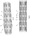
- FIGS. 40 a and 40 b are flattened views of variations of the expandable section.
- FIG. 41 illustrates a variation of the unexpandable section integral with the central shaft and distal end of the expandable attachment device.
- FIG. 42 illustrates a variation of cross-section C-C of FIG. 41 .
- FIG. 43 illustrates a variation of cross-section D-D of FIG. 41 .
- FIG. 44 is a variation of a close-up E-E of FIG. 42 .
- FIG. 45 is a distal end view of a variation of the unexpandable section integral with the central shaft and distal end of the expandable attachment device of FIG. 41 .
- FIG. 46 illustrates a variation of the center shaft integral with the unexpandable section and the distal end.
- FIGS. 47 a and 47 b are various perspective views of a variation of the distal end cap.
- FIG. 48 is a side view of a variation of the distal end cap.
- FIG. 49 is a distal end view of a variation of the distal end cap.
- FIG. 50 illustrates a variation of cross-section Z-Z of FIG. 47 a.
- FIG. 51 illustrates a variation of cross-section Y-Y of FIG. 47 b.
- FIG. 52 illustrates a variation of the expandable attachment device attached to a variation of the deployment tool.
- FIGS. 53 and 54 illustrate a variation of the expandable attachment device in unassembled and assemble configurations, respectively, and a method for assembling the expandable attachment device.
- FIG. 55 illustrates a variation of the deployment tool in an unassembled configuration.
- FIG. 56 is a close-up perspective view of the end of the deployment tool in an assembled configuration.
- FIG. 57 illustrate variations of the expandable attachment device in radially expanded configurations, and measurements thereof.
- FIGS. 58 and 59 illustrate a variation of the expandable attachment device and a method for radially expanding the device.
- FIGS. 60 and 61 illustrate a variation of the expandable attachment device and a method for radially expanding the device.
- FIG. 62 illustrates a variation of the expandable attachment device and a method for radially expanding the device.
- FIGS. 63 and 64 illustrate a variation of the expandable attachment device and a method for radially expanding the device.
- FIG. 65 illustrates a variation of cross-section F-F of FIG. 64 .
- FIG. 66 is a perspective view of a variation of the expandable section in a radially contracted configuration.
- FIG. 67 is an end view of the variation of the expandable section of FIG. 66 in a radially contracted configuration.
- FIG. 68 is an end view of the variation of the expandable section of FIG. 66 in a radially expanded configuration.
- FIGS. 69 and 70 are perspective views of variations of the expandable section.
- FIG. 71 illustrates a variation of the expandable section with the deployment rod.
- FIGS. 72 and 73 illustrate variations of cross-section W-W of FIG. 71 .
- FIGS. 74 and 75 illustrate variations of cross-section W-W of FIG. 72 .
- FIGS. 76 and 77 illustrate a variation of the expandable section of FIG. 70 with a wedge, and a method for using the same.
- FIG. 78 illustrates a variation of cross-section V-V of FIG. 77 .
- FIGS. 79 a , 79 b , 79 c , and 79 d illustrate perspective, top, side, and rear views of a variation of the manipulation tool.
- FIGS. 80 through 82 illustrate a variation of the expandable section and a method for radially expanding the same.
- FIGS. 83 and 84 illustrate variations of the expandable section.
- FIGS. 85 and 86 illustrate various perspective views of a variation of the expandable attachment device in a radially contracted configuration.
- FIG. 87 illustrates a variation of cross-section G-G of FIG. 86 .
- FIGS. 88 and 89 illustrate various perspective views of the variation of the expandable attachment device of FIGS. 85 through 87 in a radially expanded configuration.
- FIGS. 90 and 91 illustrate a variation of the expandable attachment device and a method for radially expanding the device.
- FIGS. 92 and 93 illustrate a variation of the expandable attachment device and a method for radially expanding the device.
- FIG. 94 illustrates a variation of the expandable attachment device and a method for radially expanding the device.
- FIGS. 95 and 96 illustrate proximal end views of variations of the expandable attachment device.
- FIGS. 97 and 98 illustrate a variation of a the expandable section in radially contracted and expanded configurations, respectively.
- FIGS. 99 and 100 are side and proximal end views, respectively, of a variation of the expandable section with the center shaft.
- FIGS. 101 and 102 are side and proximal end views, respectively, of a variation of the expandable section.
- FIGS. 103 and 104 are front and side perspective views, respectively, of a variation of the expandable element.
- FIGS. 105 through 107 illustrate variations of the expandable element.
- FIGS. 108 and 109 illustrate a variation of the expandable section and distal end and a method for radially expanding the device.
- FIGS. 110 and 111 illustrate variations of the expandable section.
- FIGS. 112 and 113 illustrate a variation of the expandable attachment device and a method for radially expanding the device.
- FIG. 114 illustrates a variation of the expandable element of FIGS. 112 and 113 .
- FIG. 115 illustrates a variation of cross-section K-K of FIG. 114 .
- FIGS. 116 and 117 illustrate cross-sections H-H and J-J, respectively, of FIGS. 112 and 113 , respectively.
- FIGS. 118 and 119 illustrate a variation of the expandable attachment device and a method for radially expanding the device.
- FIG. 120 a illustrates a variation of multiple expandable elements.
- FIG. 120 b is an end view of a variation of the expandable section in a contracted configuration.
- FIG. 120 c is an end view of a variation of the expandable section in a radially expanded configuration and a method for radially expanding the expandable section.
- FIGS. 121 , 122 , 123 and 124 are side, perspective, distal end, and proximal end views, respectively, of a variation of the expandable attachment device in a radially contracted configuration.
- FIGS. 125 , 126 , and 127 are distal end, proximal end, and side views, respectively, of a variation of the expandable attachment device of FIGS. 121 through 124 in a radially expanded configuration.
- FIGS. 128 and 129 are front and perspective views, respectively, of a variation of the expandable section in a radially contracted configuration.
- FIGS. 130 and 131 are front and perspective views, respectively, of the variation of the expandable section of FIGS. 128 and 129 in a radially expanded configuration.
- FIGS. 132 and 133 are front and perspective views, respectively, of the variation of the expandable section of FIGS. 128 and 129 in a radially expanded configuration.
- FIGS. 134 and 135 are perspective and side views, respectively, of a variation of the center shaft.
- FIG. 136 is an end view of a variation of the expandable section in a radially contracted configuration.
- FIG. 137 is an end view of the expandable section of FIG. 136 in a radially expanded configuration.
- FIG. 138 is a perspective view of the first expandable element and the second expandable element of FIG. 137 .
- FIG. 139 is a perspective view of the expandable section of FIG. 137 .
- FIGS. 140 through 142 illustrate variations of the expandable section in radially contracted configurations.
- FIG. 143 illustrates a variation of the expandable attachment device with the expandable section of FIG. 141 .
- FIG. 144 illustrates an unassembled expandable attachment device of FIG. 143 .
- FIG. 145 illustrates a variation of cross-section L-L of FIG. 143 during use.
- FIG. 146 illustrates a variation of the expandable attachment device.
- FIGS. 147 , 148 and 149 illustrate variations of the expandable attachment device with the expandable section of FIGS. 140 , 141 and 142 , respectively.
- FIGS. 150 and 151 illustrate side and perspective views, respectively, of a variation of the expandable section in a radially contracted configuration.
- FIGS. 152 and 153 illustrate variations of the expandable section in radially expanded configurations.
- FIG. 154 is a lateral view of the spine.
- FIG. 155 illustrates cross-section M-M of FIG. 154 .
- FIG. 156 illustrates cross-section M-M of FIG. 154 with an expandable attachment device delivered into the pedicle and/or vertebral body.
- FIG. 157 is a partial see-through lateral view of the spine with a variation of the expandable attachment device delivered to, and radially expanded in, the pedicle and/or vertebral body.
- FIG. 158 illustrates cross-section M-M of FIG. 157 .
- FIG. 159 illustrates a variation of a method for using a variation of the expandable attachment device to treat a broken bone.
- FIG. 160 illustrates a variation of a method for using two variations of the expandable attachment devices to treat a broken bone.
- FIGS. 161 and 162 illustrate a variation of a method for attaching an end attachment to the remainder of a variation of the expandable attachment device.
- FIG. 163 illustrates a variation of method for using a variation of the expandable attachment devices with a fixation rod in the spine.
- FIG. 164 illustrates a variation of a method for using a variation of the expandable attachment devices with end attachments in the spine.
- FIGS. 165 through 167 illustrate a variation of a method for expanding first and second expandable sections on a variation of the expandable attachment device.
- FIGS. 168 and 169 illustrate variations of methods for using a variation of the expandable support device in the spine.
- FIG. 170 is an anterior view of a variation of a method for using the expandable attachment device in a spine with a fixation plate.
- FIGS. 171 and 172 are sagittal cross-sections of a variation of a method for using the expandable attachment device in a spine with a fixation plate.
- FIG. 173 illustrates a variation of the deployment tool.
- FIGS. 174 through 178 illustrate a variation of a method for implanting a variation of the expandable attachment device for use as a tooth anchor.
- FIGS. 179 and 180 illustrate a variation of a method for implanting a variation of the expandable attachment device for use as a tooth anchor.
- FIG. 181 illustrates a variation of the expandable attachment device.
- FIG. 182 is a close-up view of the expandable attachment device of FIG. 181 .
- FIG. 183 illustrates cross-section S-S of the expandable attachment device of FIG. 181 .
- FIG. 184 illustrates a variation of close-up section T-T of the expandable attachment device of FIG. 183
- FIG. 185 is a close-up view of a variation of the expandable attachment device.
- FIG. 186 is an expanded view of the expandable attachment device of FIG. 185 .
- FIG. 187 illustrates a variation of cross-section U-U of FIG. 186 .
- FIG. 5 illustrates that the expandable attachment device 22 can have an unexpandable section 28 at a proximal end, an expandable section 24 at a medial length along the expandable attachment device 22 , and a distal end 34 .
- the unexpandable section 28 can be distal to the expandable section 24
- the expandable attachment device 22 can have more than one expandable section 24 and/or unexpandable section 28 that can be interspersed with each other.
- the expandable attachment device 22 can have an expandable attachment device axis 26 .
- the expandable device axis 26 can be substantially straight or curved.
- the proximal end of the expandable attachment device can have a tip 32 .
- the tip 32 can be sharpened or otherwise configured to seat the expandable attachment device in bone (e.g., having cutting teeth).
- the unexpandable section 28 can have unexpandable thread 30 , for example, configured to screw the expandable attachment device 22 into bone.
- FIG. 5 shows that the expandable attachment device 22 can have a radially contracted configuration.
- FIG. 6 illustrates that the expandable attachment device 22 can have a radially expanded configuration.
- the expandable section can be radially expanded, as shown by arrows.
- the expandable section 24 can be resiliently and/or deformably expandable.
- the expandable sections 24 can be radially expanded by axial compression (e.g., see FIGS. 8 - 11 ), rotation (e.g., see FIGS. 26 - 29 ), use of a lever such as a wedge, ramp or jack (e.g., see FIGS. 58 - 64 ), or combinations thereof.
- the expandable section 24 can be biased to resiliently radially expand.
- the expandable section 24 can be self-expandable or releasable spring.
- the expandable section 24 can be resiliently radially expandable and can be additionally deformably radially expandable to a larger radius than achieved by resilient expansion alone.
- the expandable section 24 can have one or more anchors extending radially therefrom when the expandable section is in the radially expanded configuration.
- the anchors can be brads, hooks, pins, teeth, fasteners, pegs, screws, skewers, spikes, stakes, or combinations thereof.
- FIG. 7 illustrates that the expandable attachment device axis 26 can be curved.
- the expandable attachment device axis 26 can have curved and straight lengths.
- the expandable attachment device axis 26 can have a substantially straight length along the unexpandable section 28 and the distal end 34 , and a curved length along the expandable section 24 .
- FIGS. 8 and 9 illustrates that the expandable attachment device 22 can be radially expanded by applying a proximally-directed force to the distal end 34 as shown by arrows of FIG. 8 .
- the proximally-directed force can be substantially parallel to the expandable attachment device axis 26 .
- the proximal force can be opposed by a distal force applied, for example, by the bone and/or a deployment tool.
- the expandable section can then radially expand, as shown by arrows in FIG. 9 .
- FIGS. 10 and 11 illustrate that the expandable attachment device 22 can have expandable thread 66 on the expandable section and unexpandable thread 30 on the unexpandable section.
- the expandable thread can radially expand with the remainder of the expandable section.
- the expandable attachment device shown in FIGS. 10 and 11 can be radially expanded by the method as shown in FIGS. 8 and 9 .
- FIGS. 12 and 13 illustrate that the expandable attachment device can be radially expanded by applying a distally-directed force to the distal end as shown by arrow.
- the distally-directed force can be substantially parallel to the expandable attachment device axis.
- the distal force can be opposed by a proximal force applied, for example, by the bone and/or a deployment tool.
- the expandable section can then radially expand, as shown by arrows in FIG. 13 .
- FIGS. 14 and 15 illustrate that the expandable attachment device can have expandable thread on the expandable section and unexpandable thread on the unexpandable section.
- the expandable thread can radially expand with the remainder of the expandable section.
- the expandable attachment device shown in FIGS. 14 and 15 can be radially expanded by the method as shown in FIGS. 12 and 13 .
- FIG. 16 illustrate that substantially the entire length of the expandable attachment device can be the expandable section.
- the distal end can extend distally from the expandable section.
- FIG. 17 illustrates that the entire expandable section can radially expand.
- FIGS. 16 and 17 illustrate that the expandable section can have expandable thread.
- FIGS. 18 and 19 illustrate the variation of the expandable attachment device of FIGS. 16 and 17 , respectively, without expandable thread.
- FIG. 20 illustrates that the expandable attachment device can have, from distal to proximal, a first expandable section, a third expandable section, and a second expandable section.
- the first, second and third expandable sections can radially expand at different rates (e.g., under different deployment loads, for example one or more are resiliently and one or more are deformably expandable).
- the first and second expandable sections can radially expand at the same rate
- the third expandable section can radially expand at a lesser rate.
- FIG. 21 illustrates that the expandable section 24 can have a number of struts 38 attached to each other at joints 40 .
- the struts 38 can be configured to form diamond-shaped ports 42 .
- the expandable section 24 can have a distal hoop 36 b at the distal end and/or a proximal hoop 36 a at the proximal end.
- the hoops 36 can attach to all of the struts 38 at the respective end.
- the hoops 36 and struts 38 can all be integral with and/or attached to each other.
- FIG. 22 illustrates that longitudinal compressive force 44 can be applied to the expandable section, for example resulting in radial expansion 46 .
- the struts can deform near the joints.
- the hoops can remain substantially static.
- FIGS. 23 and 24 illustrates that the expandable section can be radially expanded by longitudinally compressing the expandable section.
- the deployment tool 60 (or expandable attachment device 22 ) can have an anvil 142 and a deployment cap 47 .
- the anvil 142 can be the distal end and/or the unexpandable section.
- the deployment cap 47 can be part of or attached to the unexpandable section and/or the distal end, for example, the opposite of the anvil 142 .
- the expandable section can be compressed between the anvil 142 and the deployment cap 47 .
- the deployment tool 60 (or expandable attachment device 22 ) can have a deployment rod 128 , for example to transmit the compressive force to the deployment cap 47 .
- the deployment rod 128 can be releasably attached to the deployment cap 47 , for example via a releasable deployment anchor 49 .
- the releasable deployment anchor can be released and the deployment rod can be removed after the expandable section is radially expanded.
- FIGS. 25 a - e illustrate variations of the expandable section's strut, port and joint configuration.
- FIG. 25 a illustrates that the ports can be larger near a central region 54 near the longitudinal median of the expandable section than in end regions 52 .
- the lengths of the expandable section with larger ports can radially expand during longitudinal compression before the lengths of the expandable section with smaller ports.
- the expandable section can have thread 50 and/or another releasable attachment configuration at one or both ends.
- the expandable section can have a tool port 48 configured to receive a deployment tool (e.g., a deployment rod) through the proximal end of the expandable section.
- a deployment tool e.g., a deployment rod
- FIG. 25 b illustrates that the struts and ports can be substantially identical along the entire length of the expandable section.
- FIG. 25 c can have main struts 56 and smaller folded cross-struts 58 that attach to multiple main struts 56 .
- FIG. 25 d illustrates that the struts and ports can be substantially identical along the entire length of the expandable section and that the ports can be longer in the longitudinal direction that in the angular direction, with respect to the expandable section.
- FIG. 25 e that the struts and ports can be substantially identical along the entire length of the expandable section and that the ports can be longer in the longitudinal direction that in the angular direction, with respect to the expandable section, and smaller and more numerous than as shown in FIG. 25 d.
- FIGS. 26 and 27 illustrate that when the distal end and/or expandable section is rotated, as shown by arrow in FIG. 26 , that the expandable section can radially expand, as shown by arrows in FIG. 27 .
- FIGS. 26 and 27 illustrate that the expandable section can be distal to the unexpandable section.
- FIGS. 28 and 29 illustrate that when the distal end and/or expandable section is rotated, as shown by arrow in FIG. 28 , that the expandable section can radially expand, as shown by arrows in FIG. 29 .
- FIGS. 28 and 29 illustrate that the unexpandable section can be distal to the expandable section.
- FIG. 30 illustrates that the expandable section can have a slot 62 radially through the expandable section.
- the slot 62 can have a helical configuration along the expandable section.
- the distal end can be threaded.
- the expandable attachment device can be detachably attached to a deployment tool 60 .
- FIG. 31 illustrates that the expandable section can have a textured surface.
- the expandable attachment device can have a distal end cap 64 at the distal end.
- the distal end cap can have a substantially spherical configuration.
- FIG. 32 illustrates that the expandable section can have a helical slot 62 and an expandable thread 66 .
- the expandable thread 66 can be helical at substantially the opposite angle of the helical slot 62 .
- the expandable thread can be helical at a positive or negative angle with respect to a plane perpendicular to the expandable attachment device axis.
- the helical slot can be helical at the opposite-signed (i.e., positive or negative) angle to the expandable thread.
- FIG. 32 illustrates that the distal end of the distal end cap can have cap deployment tool attachments 68 , for example cross-notches on the head of the cap 64 .
- the cross-notches can be utilized to engage the distal end cap 64 with an engagement tool.
- the distal end of the center shaft can have a shaft deployment tool attachment 70 , for example, an allen or hexagonal or septagonal socket.
- FIG. 34 illustrates that when the expandable section is in a radially contracted configuration, the expandable thread 66 can protrude to about the same radius at the unexpandable thread with respect to the expandable attachment device axis.
- FIGS. 35 a and 35 illustrate that the expandable section can be separate to the remainder of the expandable attachment device.
- FIG. 35 b illustrates that the helical slot can extend through the thickness of the wall of the expandable section.
- FIGS. 36 through 39 illustrate additional details of the expandable section.
- FIG. 38 illustrates that the expandable section can have an expandable section wall 72 can have numerous helical slots in a slotted wall section 74 .
- the expandable section wall can have one or more unslotted wall sections 76 , for example at the distal and proximal ends of the expandable section.
- the slots can have joints at one both ends of the slots.
- FIG. 39 illustrates that the joints can be circular.
- the joints can have a larger, smaller or equal diameter to the width of the slot.
- FIG. 40 illustrates that the expandable section wall can have one or more retrograde slot sections 76 , for example at each end of the slotted wall section 74 .
- the retrograde slot section 76 can have slots 62 in the substantially opposite direction of the slots 62 in the remainder of the slotted wall section 74 .
- the primary (i.e., non-retrograde) slots can be helical at a positive or negative angle with respect to a plane perpendicular to the expandable attachment device axis.
- the retrograde slots can be helical at the opposite-signed (i.e., positive or negative) angle to the primary slots.
- the retrograde slot section 76 can, for example, act as a shock absorber.
- the retrograde slot section 76 can increase maximum radial expansion of the expandable section.
- the slots 62 can be sinusoidal along the length of the expandable section.
- FIG. 40 b illustrates that the ends of the slots 62 can be placed at different lengths from the ends of the expandable section. For example, varying the lengths of adjacent slots can diffuse strain on the expandable section.
- FIGS. 41 through 45 illustrate dimensions of the expandable section (dimensions are shown on attachment B).
- FIG. 41 illustrates that the unexpandable section can be integral with a center shaft and the distal end.
- FIG. 43 illustrates that the distal end can have the shaft deployment tool attachment therethrough.
- FIG. 46 illustrates a close up of the distal end of the unexpandable section, center shaft and distal end.
- FIGS. 47 a and 47 b illustrate that the distal cap end can have a cap ball and a cap sleeve.
- the cap ball and/or cap sleeve can have internal cap thread along all or part of the length.
- FIGS. 48 through 51 illustrate dimensions of the expandable section (dimensions are shown on attachment C).
- FIG. 52 illustrates that the expandable attachment device can be releasably attached to the deployment tool.
- the deployment tool can have deployment engagement teeth that can align and intersect with the distal end cap, for example at the cap deployment tool attachments.
- FIG. 53 illustrates that the expandable attachment device can be dissembled in separate elements.
- the unexpandable section can be integral with the center shaft.
- the center shaft for example at the distal end, can have shaft cap attachments that can attach to the distal end cap.
- FIG. 54 illustrates that the expandable attachment device can be assembled by translating the expandable section over the center shaft, as shown by arrow.
- the distal end cap can then be rotated, as shown by arrow, onto the shaft cap attachments.
- FIGS. 55 and 56 illustrate that the deployment tool can have a post tool and a tooth tool.
- the tooth tool can be separate, attached, or integral with the post tool.
- the post tool can have a post tool hand.
- the post tool handle can be attached to or integral with a deployment engagement post.
- the post tool can have a deployment tool suspension.
- the deployment engagement post can be configured to attach to the shaft deployment tool attachment.
- the tooth tool can have deployment engagement teeth.
- the deployment engagement teeth can be configured to attach to the cap deployment tool attachment.
- the tooth tool can have a tooth tool handle, for example extending radially from the remainder of the tooth tool.
- the deployment tool suspension can resiliently separate the tooth tool and the post tool.
- the deployment tool suspension can suspend the deployment engagement post from the post tool handle.
- FIG. 57 illustrates the expandable section in a radially expanded configuration can have an outer diameter 104 from about 7 mm (0.3 in.) to about 15 mm (0.59 in.), for example about 9.99 mm (0.393 in.) or about 9.31 mm (0.367 in.).
- FIGS. 58 and 59 illustrate that an external wedge can be inserted, as shown by arrow in FIG. 58 , into the expandable section.
- the expandable section can then radially expand, as shown by arrows in FIG. 59 .
- the external wedge can be left in the expandable section or removed from the expandable section.
- the wedge can have a transverse cross section that is square, round (e.g., a conical wedge), rectangular, oval, or combinations thereof.
- FIG. 60 illustrates that the expandable attachment device can have a first external wedge and a second external wedge.
- the second external wedge can be attached to or integral with the unexpanded section and/or otherwise positioned between the expandable section and the unexpanded section when the expandable section is in a radially contracted configuration.
- the second external wedge can be pointing narrow end-first toward the distal end of the expandable attachment device.
- a proximally-directed force can be applied, as shown by arrow, to the first external wedge and/or the distal end.
- the expandable section can then radially expand, as shown by arrows in FIG. 61 , as the wedges are pushed into a channel in the expandable section.
- FIG. 62 illustrates that the expandable attachment device can have a first expandable section, second expandable section, and third expandable section.
- the expandable sections can each have one or two external wedges entering into an inner hollow or channel, as shown in FIGS. 58 through 61 .
- FIG. 63 illustrates that the expandable section can have one or more expansion elements configured to radially expand.
- the expandable section can have one, two or more internal wedges.
- the expansion elements can have ramps configured to slidably engage the internal wedge when the internal wedge is compressed into the expansion elements.
- FIG. 64 illustrates that the internal wedges can be compressed, as shown by arrows, into the expansion elements.
- the expansion elements can then radially expand, as shown by arrows.
- FIG. 65 illustrates that the internal wedges can interference fit with the ramps. As the internal wedges are further compressed, the internal wedges can cause a deformation or other translation of the expansion elements.
- FIGS. 66 and 67 illustrates that the expandable section can have a top wall and a bottom wall connected by two side walls.
- the top wall and bottom wall can have expandable thread.
- the side wall can have expandable thread.
- the top wall and/or bottom wall can have one or more ramps extending inwardly into the longitudinal channel of the expandable section.
- FIG. 68 illustrates that in a radially expanded configuration, the top wall and bottom wall can translate radially outward, as shown by arrows.
- the side walls can deform and/or translate radially inward.
- FIG. 69 illustrates that the top wall and/or bottom wall can have a manipulation channel passing completely or partially therethrough in a substantially longitudinal direction.
- the manipulation channels can be, for example, cylindrical.
- FIG. 70 illustrates that the top wall and/or the bottom wall can have longitudinal guide slots 124 .
- the guide slots 124 can be in fluid communication with the longitudinal channel.
- the guide slots 124 can be parallel with the ramps.
- FIGS. 71 and 72 illustrate that a first wedge and a second wedge can be inserted into the longitudinal channel of the expandable section.
- the second wedge and/or first wedge can be integral with the deployment rod.
- the first wedge can have a longitudinal wedge channel.
- the deployment rod can slidably attach to the first wedge through the wedge channel.
- the first wedge and second wedge can have configurations that substantially match the respective ramps.
- FIG. 73 illustrates that the opposing compressive first and second translational forces can be applied to the first wedge and the deployment rod, respectively.
- the first and second wedges can be deformably translated into the expandable section.
- FIG. 74 illustrates that the expandable section can radially expand, for example near the ends of the expandable section and/or to the length the wedges are inserted.
- FIG. 75 illustrates that the expandable section and wedges can be configured to radially expand on only one side.
- the wedges can have angled slopes on one side of the wedge and flat sides on the opposing side of the angled slopes.
- the expandable section can have a wall with tapered thickness on the side to be radially expanded, and a constant thickness wall, and/or a thicker wall than the tapered wall, on the side opposite the tapered wall.
- FIG. 76 illustrates that the wedge can have a wedge rail.
- the wedge rail can align with and insert into the guide slot 124 .
- FIGS. 77 and 78 illustrate that the wedge rail can slidably attach to the guide slot 124 .
- FIGS. 79 a through 79 d illustrate that a manipulation tool can have a base, a first leg extending from the base, and a second leg extending from the base.
- the legs can be configured to fit into the manipulation channels of the expandable section.
- the legs can be used to insert into the manipulation channels and manipulate (e.g., translation, rotation, deformation) the expandable section.
- Legs can articulate with respect to the base. The leg articulation can be controlled by controls (not shown) on the base, such as a handle or trigger.
- FIG. 80 illustrates that a cone or mandrel can be translated into the longitudinal channel of an expandable section having struts and joints.
- the expandable section can have no hoops.
- the expandable section can have an anvil at the opposite end of the cone.
- FIG. 81 illustrates that the cone can be forced toward the anvil, and/or the anvil can be forced toward the cone, resulting in longitudinal translation of the cone towards the anvil, through the longitudinal channel.
- the expandable section over the cone for example at the distal end, can radially expand, as shown by arrows.
- FIG. 82 illustrates that the cone can be longitudinally translated along the entire length of the expandable section.
- the cone can be received in the anvil.
- the entire length of the expandable section can radially expand, as shown by arrows.
- the expansion can be resilient and/or deformable.
- the cone can be removed or left in place.
- FIG. 83 illustrates that the expandable section can have plates that can be integral with or attached to the joints and/or struts.
- the plates can be configured to be flexibly attached to or integral with the remainder of the expandable section.
- Each plate can be configured to substantially cover each port.
- FIG. 84 illustrates that a first plate and a second plate can cover a port.
- the first plate can extend from a first joint adjacent to the port.
- the second plate can extend from a joint opposite to the first plate.
- FIGS. 85 through 87 illustrate an expandable attachment device that can have an expandable section that can have a first expandable element directly or indirectly slidably attached to a second expandable element.
- the first expandable element can be slidably attached to the center shaft to translate up when the center shaft is translated distally
- the second expandable element can be slidably attached to the center shaft to translate down when the center shaft is translated distally.
- the center shaft can be substantially inside the expandable element.
- the center shaft can be substantially outside the expandable element.
- the first expandable element can have the tip.
- the tip can be pointed and/or flat.
- the first expandable element can have thread on a top side.
- the first expandable element can have a peg (shown in FIG. 87 ) that can extend radially inward.
- the peg can be configured to slide in a first track on the side of the central shaft.
- the first track can extend from being low distally to high proximally.
- the second expandable element can have thread on a bottom side.
- the first expandable element can have a peg that can extend radially inward similar to that of the first expandable element.
- the peg can be configured to slide in a second track on the side of the central shaft opposite the side of the first track.
- the first track can extend from being high distally to low proximally.
- FIG. 88 illustrates that when the expandable attachment device is in a radially expanded configuration, the first expandable element can be separated from the second element.
- the peg of the first expandable element can be forced upward, forcing the first expandable element upward.
- the peg of the first expandable element can be forced upward, as shown by arrow in FIG. 88 , forcing the second expandable element downward.
- the peg of the second expandable element can be forced downward, forcing the second expandable element upward, as shown by arrow in FIG. 88 .
- FIG. 94 illustrates that the expandable element devices can be substantially triangular from a lateral perspective.
- the expandable elements can be slidably attached to each other.
- the expandable attachment device can have multiple expandable elements.
- a compressive force for example including a proximally directed force applied to the distal end (as shown by arrow) and/or the distal expandable element, can force the expandable elements to radially expand, as shown by arrows.
- FIG. 95 illustrates that the distal end of the expandable attachment device, for example the tip, can have a transverse cross-section that can be round, circular, oval, square, rectangular, triangular, or combinations thereof.
- the expandable section can have a transverse cross-section that can be round, circular, oval, square, rectangular, triangular, or combinations thereof.
- FIG. 96 illustrates a variation of the expandable section.
- FIG. 97 illustrates that the expandable section in the radially contracted configuration can have a straight expandable section axes.
- FIG. 98 illustrates that the expandable section in a radially expanded configuration can have a straight or curved expandable section axis, and/or that the expandable section axis can be at an angle with respect to the expandable section axis in the radially contracted configuration.
- FIGS. 99 and 100 illustrates that the expandable section can have a series of expandable elements having a slidably attached center shaft therethrough.
- the center shaft can have a center shaft anchor.
- the center shaft anchor can have a larger diameter than the diameter of the longitudinal channel. Teeth can radially extend from the expandable elements, for example from at least opposite sides of alternating expandable elements, as shown.
- FIGS. 101 and 102 illustrate that the expandable elements can have guide rails.
- the guide rails can slidably attach to receiving elements on adjacent expandable elements.
- the longitudinal channel in at least every other expandable element can be elongated in the transverse direction.
- FIGS. 103 and 104 illustrate that the expanding element can have one or two guide rails on each surface adjacent to another expanding element when assembles.
- the cross-section of the longitudinal channel in an individual expanding element can be, for example, circular, oval, square, rectangular, or combinations thereof.
- FIG. 105 illustrates that the expandable element can have one, two or more guide grooves on each surface adjacent to another expanding element when assembled.
- the guide grooves can be configured to slidably attach to the guide rails.
- FIG. 106 illustrates that the expandable element can have one or more contouring channels.
- the contouring channels can be a defined, substantially closed volume within the expandable element.
- the contouring channels can deform, for example, due to force applied against the teeth during use. When deformed, the contouring channel can, for example, reduce the stress applied on the neighboring tissue when implanted compared to the expandable element in a non-deformed configuration.
- FIG. 107 illustrates an expandable element having a number of contouring channel extending radially away from the expandable element channel.
- the contouring channels can be configured as slots open to the outside of the expandable element.
- FIG. 108 illustrates that the distal end cap can be distal to the most distal expandable element.
- the distal end cap can be, or be attached to, the center shaft anchor.
- FIG. 109 illustrates that a longitudinally compressive force, as shown by arrow, can be delivered through the distal end cap.
- the expandable elements can then radially expand, as shown by arrows.
- FIGS. 110 and 111 illustrate the expandable section having nine and five expandable elements, respectively.
- FIGS. 112 and 113 illustrates that the center shaft can be configured to have one or more alternately oppositely facing integral wedges.
- the expandable section can have one or more expandable elements.
- the expandable elements can have guide rails on the proximal ends and guide grooves on the distal ends.
- the guide grooves and guide rails can constrain relative motion between the expandable elements to a single degree of freedom (e.g., lateral motion).
- the internal surfaces of the expandable elements can have alternately oppositely facing internal ramps that can be configured to abut the integral wedges.
- FIG. 113 illustrates that the center shaft can be translated relative to the expandable section, for example with the center shaft being translated out of the expandable section.
- the expandable elements can then radial expand in opposite directions as the adjacent expandable elements, as shown by arrows.
- FIG. 114 illustrates that the expandable element can have one or two guide grooves in the distal end of the expandable element.
- the guide grooves can be notches in the wall around the longitudinal channel.
- the expandable element can have one or two guide rails at the proximal end of the expandable element.
- the guide rails can be configured to slidably attach to the guide grooves when one expandable element in stacked on another expandable element.
- FIG. 115 illustrates that the internal ramp can be a slope on the internal surface of the longitudinal channel.
- the thread can be on a single side of the expandable element.
- FIGS. 116 and 117 illustrate that when the integral wedges of the center shaft press into the internal ramps of the expandable elements, as shown by arrows in FIG. 117 , the expandable elements can be pushed radially outward by the integral wedges, as shown by arrows.
- FIG. 118 illustrates that the expandable section can have first, second, third and more expandable elements that can be cams or other offset-rotation elements.
- FIG. 119 illustrates that the distal end can be rotated, as shown by arrow. The expandable elements can then radially translate or expand, as shown by arrows. The expandable elements can translate at different timings, so that the
- FIG. 120 a illustrates that the expandable elements can have a center shaft extending through the expandable elements.
- the center shaft can be offset from the center of area of the expandable element in the plane transverse to the expandable attachment device axis.
- FIG. 120 b illustrates that the expandable section in a radially contracted configuration can have all of the expandable elements substantially aligned along the expandable attachment device axis.
- FIG. 120 c illustrates that the expandable section can be radially expanded by rotating the center shaft and/or rotating the expandable elements around the center shaft.
- the cam expandable elements can splay and radially expand.
- FIG. 121 illustrates that the expandable attachment device can have multiple expandable elements eccentrically attached to a center shaft, and/or with lobed configurations.
- FIGS. 122 through 124 illustrate that the expandable attachment device can have one through four expandable elements eccentrically attached to a center shaft (not shown).
- the expandable elements can have teeth radially extending from the expandable elements.
- FIGS. 125 through 127 illustrate the expandable attachment device with eccentrically attached expandable elements in a radially expanded configuration.
- FIGS. 128 and 129 illustrate that the expandable section can have a first, second and third expandable element.
- the expandable elements can be slidably attached by interlocking rails and tracks.
- the rails and tracks can constrain relative motion between adjacent expandable elements to one degree of freedom (e.g., vertical relative motion).
- the expandable elements can have longitudinal channels configured, for example as shown, to receive a multi-lobed center shaft and be controllable as shown in FIGS. 128 through 133 .
- the configuration of the longitudinal channel in each expandable element can be the same or different as the other expandable elements.
- the first expandable element and the third expandable element can have substantially identically configured longitudinal channels.
- the second expandable element can have a longitudinal channel configured to be a horizontally reversed configuration of the longitudinal channel of the first expandable element.
- the second expandable element can have a longitudinal channel configured to be-about a 180° rotation of the longitudinal channel of the first expandable element.
- the center shaft can have a first lobe and a second lobe.
- FIGS. 130 and 131 illustrate that the center shaft can be rotated, as shown by arrow.
- the lobes can exert forces against the expandable elements.
- the expandable elements can be translated in a direction substantially perpendicular to the longitudinal axis of the center shaft.
- the first and third expandable elements can translate toward the up, as shown by arrows.
- the second expandable element can translate down, as shown by arrows.
- FIGS. 132 and 133 illustrates that the center shaft can be rotated in the opposite direction as shown in FIGS. 130 and 131 .
- the expandable elements can translate in the opposite direction as shown from FIG. 131 .
- FIGS. 134 and 135 illustrate a center shaft that can have alternating first lobes and second lobes along the length of the center shaft.
- the first lobes can have a first lobe axis.
- the second lobes can have a second lobe axis.
- the angle between the first lobe axis and the second lobe axis can be a lobe angle.
- the lobe angle can be from about 90° to about 180°.
- the first lobes can be actuated in an opposite rotational direction than the second lobes.
- FIG. 136 illustrates an expandable section that can have a first expandable element that can translate in the opposite direction of the second expandable element when the center shaft is rotated.
- the first expandable element can have first element teeth.
- the second expandable element can have second element teeth.
- the element teeth can extend radially inward in the longitudinal channel.
- the first element teeth can be on the opposite side of the longitudinal channel as the second element teeth.
- the center shaft can have gear teeth extending radially outward. The gear teeth can engage the first element teeth can the second element teeth.
- FIGS. 137 through 139 illustrate that when the center shaft is rotated, the first expandable element can translate up at the same rate that the second expandable element can translate down.
- FIG. 140 illustrates an expandable section that can have thread or teeth on one, two, three or more spines extending radially from the wall of the expandable section.
- the wall In a radially contracted configuration, the wall can have multiple folds, for example two folds between each two adjacent spines. The folds can be unevenly spaced between the adjacent spines.
- FIG. 141 illustrates that the wall can have two folds between each two adjacent spines. The folds can be evenly spaced between the adjacent spines.
- FIG. 142 illustrates that the walls can have one fold between adjacent spines.
- the spines can extend radially inward and/or outward from the wall.
- FIGS. 143 and 144 illustrate that the expandable section (shown for exemplary purposes as the expandable section of FIG. 141 ) can be loaded on the center shaft of an expandable attachment device.
- the expandable section can be placed between a first cone and a second cone on the expandable attachment device.
- the expandable attachment device can have a mandrel.
- the second cone can be part of the mandrel.
- FIG. 145 illustrates that the mandrel can be pushed, as shown by arrow, toward the expandable section.
- the expandable section can radially expand as shown by arrow.
- the distal end can be configured to attach to a separate device, such as a fixation rod or plate.
- the distal end can be threaded.
- FIG. 146 illustrates that the expandable attachment device can have a first expandable section and a second expandable section.
- Each expandable section can be between a first cone and a second cone, and can be radially expanded as described herein, including as shown in FIG. 145 .
- FIGS. 147 through 149 illustrate the expandable sections of FIGS. 140 through 142 , respectively, loaded on the center shaft of the expandable attachment device.
- FIGS. 150 and 153 illustrate that the expandable section can have about four angled ports. Each port can have a joint. Between two adjacent ports can be an individual expandable segment, for example the first expandable segment and the second expandable segment, as shown.
- FIG. 152 illustrates that a longitudinally compressive force, as shown by arrows, can be applied to the expandable section.
- the expandable segments can rotate, as shown by arrows, around the adjacent joints.
- the ports can close.
- the expandable section In the radially expanded configuration, the expandable section can have a distal end shifted laterally from the proximal end.
- FIG. 153 illustrates that the expandable section can have larger ports and/or the expandable section can be over compressed, causing deformation after the ports have closed.
- the distal end and the proximal end of the expandable section can be laterally aligned.
- FIG. 154 illustrates a side view of a spine.
- FIG. 155 illustrates that harder, cortical bone surrounds softer, cancellous bone in the vertebra.
- FIG. 156 illustrates that the expandable attachment device can be translated and/or rotated into the pedicle and/or into the vertebral body.
- the expanded section can be positioned in the cortical bone.
- FIGS. 157 and 158 illustrate that the expandable section can be radially expanded, for example in the cancellous bone of the pedicle and/or the vertebral body.
- the radius of the radially expanded section can be larger than the entry hole created to insert the attachment device into the vertebra.
- the distal end can extend from the bone.
- a separate device such as a fixation rod or plate, can be attached to the distal end.
- FIG. 159 illustrates that an expandable attachment device can be used to treat a long bone break, such as in the femur or humerus.
- the expandable attaclunent device can be inserted into the cancellous and/or cortical part of the bone.
- the expandable attachment device can be positioned to have a first exp ⁇ ndable section on a first side of the bone fracture.
- the expandable attachment device can be positioned to have a second expandable section on a second side of the bone fracture.
- the expandable attachment device can have an unexpandable section between the first and second expandable sections.
- the unexpandable section can be positioned across the bone fracture.
- FIG. 160 illustrates that a first expandable attachment device 22 a can be placed in a first section of the bone (e.g., the femur head).
- a second expandable attachment device 22 b can be placed in a second section of the bone.
- the second expandable attachment device 22 b can have a collar configured to fixedly receive the unexpandable section of the first expandable attachment device.
- the unexpandable section of the first expandable attachment device 22 a can be fixedly attached to the collar.
- FIGS. 161 and 162 illustrates that the expandable attachment device can have an end attachment configured to be attached, as shown by arrow, to the distal end.
- the expandable attachment device can be positioned in a bone and radially expanded.
- the end attachment can be attached to the distal end, as shown in FIG. 164 .
- the end attachment can be configured to attach to a separate device, such as a fixation rod or plate, as shown in FIG. 163 .
- FIG. 165 through 166 illustrates that the expandable attachment device can be deployed by radially expanding the first expandable section at a first end, and concurrently or subsequently, radially expanding the second expandable section at a second end.
- FIGS. 168 and 169 illustrate that the expandable attachment device can be positioned so the first expandable section can be radially expanded in the pedicle or vertebral body.
- the second expandable section can be radially expanded in the pedicle, vertebral body, or outside the bone, for example in the soft tissue or in a virtual space.
- a separate device, such as a fixation rod or plate can be attached to the second expandable section.
- FIGS. 170 through 172 illustrate that a fixation plate can be attached to the anterior side of the spine.
- FIG. 171 illustrates that the expandable attachment devices can be attached to the fixation plate and the first expandable section can be radially expanded.
- FIG. 172 illustrates that the second expandable sections of the expandable attachment devices can be positioned in the cancellous bone. The second expandable sections can be radially expanded, as shown by arrows, in the cancellous bone, for example in the vertebral body.
- FIG. 173 illustrates that the deployment tool can have a first handle rotatably attached to a second handle. Rotating the first handle and the second handle towards each other, as shown by arrows, can result in longitudinal compression of the expandable section of the expandable attachment device. See the incorporated applications for additional elements of the deployment tool.
- the expandable attachment device can be removably attached to the deployment head.
- FIG. 174 illustrates that an oral space can have a missing tooth.
- the missing tooth can be surrounded on one side, both sides or neither side, by teeth.
- the gum, bone, and teeth roots are also shown.
- FIG. 175 illustrates that the expandable attachment device can be screwed (e.g., rotation and translation), as shown by arrows, into the missing tooth space in the bone.
- the unexpandable thread can compact or cut bone as the expandable attachment device is inserted into the missing tooth space in the bone.
- FIG. 176 illustrates that the expandable support device can be fully inserted into the bone. The distal end can extend above the gum.
- FIG. 177 illustrates that the expandable section can be radially expanded, as shown by arrows, for example with the expandable support device fully inserted into the bone.
- FIG. 178 illustrates that a replacement tooth can be fixedly or removably attached to the distal end.
- the distal end can be configured to attach to the replacement tooth (e.g., thread, one or more latches, clasps, locks).
- the replacement tooth can be positioned between the adjacent teeth.
- the space between the replacement tooth and the gum can be partially or completely filled by a filler, for example a biocompatible cement (e.g., a bone cement).
- FIG. 179 illustrates that the expandable attachment device can have unidirectional and/or one-way teeth along all or part of the length of the expandable section.
- the expandable section can be along substantially the entire length of the expandable attachment device, for example, except for the distal end configured to attach to the replacement tooth.
- FIG. 180 illustrates that the expandable section can be radially expanded, as shown by arrows.
- the replacement tooth can then be attached as shown in FIG. 178 .
- FIGS. 181 and 182 illustrate that the expandable section can have expandable threads around one or more sections of the expandable section (e.g., for example on opposite sides of the expandable section, as shown).
- the distal wedge and/or the proximal wedge can have threads on the internal diameter or be threadless on the internal diameter.
- the internal threads can engage the proximal length of the center shaft (e.g., the proximal length of the center shaft have a smaller, larger or the same diameter as compared to the diameter of the distal length of the center shaft).
- the proximal wedge can have an internal diameter that can be larger than the threads on the center shaft so the proximal wedge can slide freely over the distal length of the center shaft and/or the proximal length of the center shaft.
- FIGS. 183 and 184 illustrate that the outer diameter of the unexpandable section can be substantially equivalent to the outer diameters of the expandable section (e.g., in a radially contracted configuration) and/or the wedges.
- the outer diameter of the expandable section (e.g., in a radially contracted configuration) can be slightly larger than, smaller than, or substantially equivalent to the outer diameter of the unexpandable section.
- the internal diameter of the expandable section and the internal diameter of one or more of the wedges can have internal threads and/or teeth, for example, configured to engage threads and/or teeth on the center shaft.
- the center shaft can have a reduced diameter (as shown) at a length near the longitudinal middle of the center shaft.
- the internal threads or teeth e.g., on the inner diameter of the expandable section
- FIGS. 185 , 186 and 187 illustrate that the wedges can be segmented.
- the proximal wedge can have adjacent and/or attached proximal wedge first and second segments.
- the distal wedge can have adjacent and/or attached distal wedge first and second segments.
- the wedge segments can be configured to individually or jointedly fixedly (e.g., via ratcheting on the center shaft and/or wedge) or releasably attach to the center shaft and/or expandable section.
- the expandable section and/or center shaft can have one or more male or female configurations (e.g., guide slots 124 , such as T-slots, as shown) and the wedge segment can have one or more corresponding female or male segments (e.g., wedge rails, such as T-extensions, as shown).
- any or all elements of the expandable attachment device and/or other devices or apparatuses described herein can be made from, for example, a single or multiple stainless steel alloys, nickel titanium alloys (e.g., Nitinol), cobalt-chrome alloys (e.g., ELGILOY® from Elgin Specialty Metals, Elgin, IL; CONICHROME® from Carpenter Metals Corp., Wyomissing, PA), nickel-cobalt alloys (e.g., MP35N® from Magellan Industrial Trading Company, Inc., Westport, CT), molybdenum alloys (e.g., molybdenum TZM alloy, for example as disclosed in International Pub. No. WO 03/082363 A2, published 9 Oct.
- nickel titanium alloys e.g., Nitinol
- cobalt-chrome alloys e.g., ELGILOY® from Elgin Specialty Metals, Elgin, IL; CONICHROME® from Carpenter
- tungsten-rhenium alloys for example, as disclosed in International Pub. No. WO 03/082363, polymers such as polyethylene teraphathalate (PET), polyester (e.g., DACRON® from E. I.
- PET polyethylene teraphathalate
- polyester e.g., DACRON® from E. I.
- poly ester amide PET
- polypropylene polypropylene
- aromatic polyesters such as liquid crystal polymers (e.g., Vectran, from Kuraray Co., Ltd., Tokyo, Japan), ultra high molecular weight polyethylene (i.e., extended chain, high-modulus or high-performance polyethylene) fiber and/or yarn (e.g., SPECTRA® Fiber and SPECTRA® Guard, from Honeywell International, Inc., Morris Township, N.J., or DYNEEMA® from Royal DSM N.
- liquid crystal polymers e.g., Vectran, from Kuraray Co., Ltd., Tokyo, Japan
- ultra high molecular weight polyethylene i.e., extended chain, high-modulus or high-performance polyethylene
- fiber and/or yarn e.g., SPECTRA® Fiber and SPECTRA® Guard, from Honeywell International, Inc., Morris Township, N.J., or DYNEEMA® from Royal DSM N.
- polytetrafluoroethylene PTFE
- expanded PTFE ePTFE
- polyether ketone PEK
- polyether ether ketone PEEK
- poly ether ketone ketone PEKK
- nylon polyether-block co-polyamide polymers
- PEBAX® from ATOFINA, Paris, France
- aliphatic polyether polyurethanes e.g., TECOFLEX® from Thermedics Polymer Products, Wilmington, MA
- polyvinyl chloride PVC
- polyurethane thermoplastic, fluorinated ethylene propylene (FEP), absorbable or resorbable polymers such as polyglycolic acid (PGA), poly-L-glycolic acid (PLGA), polylactic acid (PLA), poly-L-lactic acid (PLLA), polycaprolactone (PCL), polyethyl acrylate (PEA), polyd
- any or all elements of the expandable attachment device and/or other devices or apparatuses described herein can be, have, and/or be completely or partially coated with agents and/or a matrix a matrix for cell ingrowth or used with a fabric, for example a covering (not shown) that acts as a matrix for cell ingrowth.
- the matrix and/or fabric can be, for example, polyester (e.g., DACRON® from E. I. Du Pont de Nemours and Company, Wilmington, DE), poly ester amide (PEA), polypropylene, PTFE, ePTFE, nylon, extruded collagen, silicone, any other material disclosed herein, or combinations thereof.
- the expandable attachment device and/or elements of the expandable attachment device and/or other devices or apparatuses described herein and/or the fabric can be filled, coated, layered and/or otherwise made with and/or from cements, fillers, glues, and/or an agent delivery matrix known to one having ordinary skill in the art and/or a therapeutic and/or diagnostic agent. Any of these cements and/or fillers and/or glues can be osteogenic and osteoinductive growth factors.
- cements and/or fillers examples include bone chips, demineralized bone matrix (DBM), calcium sulfate, coralline hydroxyapatite, biocoral, tricalcium phosphate, calcium phosphate, polymethyl methacrylate (PMMA), biodegradable ceramics, bioactive glasses, hyaluronic acid, lactoferrin, bone morphogenic proteins (BMPs) such as recombinant human bone morphogenetic proteins (rhBMPs), other materials described herein, or combinations thereof.
- DBM demineralized bone matrix
- PMMA polymethyl methacrylate
- BMPs bone morphogenic proteins
- rhBMPs recombinant human bone morphogenetic proteins
- the agents within these matrices can include any agent disclosed herein or combinations thereof, including radioactive materials; radiopaque materials; cytogenic agents; cytotoxic agents; cytostatic agents; thrombogenic agents, for example polyurethane, cellulose acetate polymer mixed with bismuth trioxide, and ethylene vinyl alcohol; lubricious, hydrophilic materials; phosphor cholene; anti-inflammatory agents, for example non-steroidal anti-inflammatories (NSAIDs) such as cyclooxygenase-1 (COX-1) inhibitors (e.g., acetylsalicylic acid, for example ASPIRIN® from Bayer AG, Leverkusen, Germany; ibuprofen, for example ADVIL® from Wyeth, Collegeville, PA; indomethacin; mefenamic acid), COX-2 inhibitors (e.g., VIOXX® from Merck & Co., Inc., Whitehouse Station, NJ; CELEBREX® from Pharmacia Corp
- fractures types that can be treated with the disclosed device and method include Greenstick fractures, transverse fractures, fractures across growth plates, simple fractures, wedge fractures, complex fractures, compound fractures, complete fractures, incomplete fractures, linear fractures, spiral fractures, transverse fractures, oblique fractures, comminuted fractures, impacted fractures, and soft tissue tears, separations (e.g., avulsion fracture), sprains, and combinations thereof.
- Plastic deformations of bones can also be treated with the disclosed device and method.
- fingers e.g., phalanges
- hands e.g., metacarpals, carpus
- toes e.g., tarsals
- feet metalatarsals, tarsus
- legs e.g., femur, tibia, fibula
- arms e.g., humerus, radius, ulna
- All dimensions shown herein are exemplary.
- the dimensions shown herein can at least be expanded to ranges from about 50% to about 150% of the exemplary dimension shown herein, more narrowly from about 75% to about 125% of the exemplary dimension shown herein.
- radial expansion refers to both a volumetric increase of an element, or an increase in the radial dimension of the element itself, or the increase in the maximum radius of the element as measured from the expandable attachment device axis.
- Any elements described herein as singular can be pluralized (i.e., anything described as “one” can be more than one).
- Any species element of a genus element can have the characteristics or elements of any other species element of that genus.
- the above-described configurations, elements or complete assemblies and methods and their elements for carrying out the invention, and variations of aspects of the invention can be combined and modified with each other in any combination.
Landscapes
- Health & Medical Sciences (AREA)
- Orthopedic Medicine & Surgery (AREA)
- Life Sciences & Earth Sciences (AREA)
- Surgery (AREA)
- Public Health (AREA)
- Veterinary Medicine (AREA)
- Animal Behavior & Ethology (AREA)
- General Health & Medical Sciences (AREA)
- Heart & Thoracic Surgery (AREA)
- Nuclear Medicine, Radiotherapy & Molecular Imaging (AREA)
- Engineering & Computer Science (AREA)
- Biomedical Technology (AREA)
- Medical Informatics (AREA)
- Molecular Biology (AREA)
- Neurology (AREA)
- Epidemiology (AREA)
- Dentistry (AREA)
- Oral & Maxillofacial Surgery (AREA)
- Surgical Instruments (AREA)
- Prostheses (AREA)
Abstract
Description
Claims (20)
Priority Applications (1)
| Application Number | Priority Date | Filing Date | Title |
|---|---|---|---|
| US16/560,064 US12207854B2 (en) | 2007-03-12 | 2019-09-04 | Expandable attachment device and method |
Applications Claiming Priority (4)
| Application Number | Priority Date | Filing Date | Title |
|---|---|---|---|
| US90679107P | 2007-03-12 | 2007-03-12 | |
| PCT/US2008/003421 WO2008112308A1 (en) | 2007-03-12 | 2008-03-12 | Expandable attachment device and method |
| US12/556,820 US20100016905A1 (en) | 2007-03-12 | 2009-09-10 | Expandable attachment device and method |
| US16/560,064 US12207854B2 (en) | 2007-03-12 | 2019-09-04 | Expandable attachment device and method |
Related Parent Applications (1)
| Application Number | Title | Priority Date | Filing Date |
|---|---|---|---|
| US12/556,820 Continuation US20100016905A1 (en) | 2007-03-12 | 2009-09-10 | Expandable attachment device and method |
Publications (2)
| Publication Number | Publication Date |
|---|---|
| US20200015873A1 US20200015873A1 (en) | 2020-01-16 |
| US12207854B2 true US12207854B2 (en) | 2025-01-28 |
Family
ID=39759872
Family Applications (2)
| Application Number | Title | Priority Date | Filing Date |
|---|---|---|---|
| US12/556,820 Abandoned US20100016905A1 (en) | 2007-03-12 | 2009-09-10 | Expandable attachment device and method |
| US16/560,064 Active 2029-05-19 US12207854B2 (en) | 2007-03-12 | 2019-09-04 | Expandable attachment device and method |
Family Applications Before (1)
| Application Number | Title | Priority Date | Filing Date |
|---|---|---|---|
| US12/556,820 Abandoned US20100016905A1 (en) | 2007-03-12 | 2009-09-10 | Expandable attachment device and method |
Country Status (4)
| Country | Link |
|---|---|
| US (2) | US20100016905A1 (en) |
| EP (2) | EP3300676A1 (en) |
| JP (2) | JP5631597B2 (en) |
| WO (1) | WO2008112308A1 (en) |
Cited By (1)
| Publication number | Priority date | Publication date | Assignee | Title |
|---|---|---|---|---|
| US20220304814A1 (en) * | 2010-07-27 | 2022-09-29 | Tenon Medical, Inc. | Prostheses for Stabilizing Bone Structures |
Families Citing this family (97)
| Publication number | Priority date | Publication date | Assignee | Title |
|---|---|---|---|---|
| US6793678B2 (en) | 2002-06-27 | 2004-09-21 | Depuy Acromed, Inc. | Prosthetic intervertebral motion disc having dampening |
| AU2004212942A1 (en) | 2003-02-14 | 2004-09-02 | Depuy Spine, Inc. | In-situ formed intervertebral fusion device |
| US20040267367A1 (en) | 2003-06-30 | 2004-12-30 | Depuy Acromed, Inc | Intervertebral implant with conformable endplate |
| US8636802B2 (en) | 2004-03-06 | 2014-01-28 | DePuy Synthes Products, LLC | Dynamized interspinal implant |
| WO2006034436A2 (en) * | 2004-09-21 | 2006-03-30 | Stout Medical Group, L.P. | Expandable support device and method of use |
| FR2884406B1 (en) | 2005-04-14 | 2008-10-17 | Memometal Technologies Soc Par | INTRAMEDULAR OSTEOSYNTHESIS DEVICE OF TWO BONE PARTS, IN PARTICULAR HAND AND / OR FOOT |
| WO2006116761A2 (en) * | 2005-04-27 | 2006-11-02 | Stout Medical Group, L.P. | Expandable support device and methods of use |
| EP1903949A2 (en) * | 2005-07-14 | 2008-04-02 | Stout Medical Group, L.P. | Expandable support device and method of use |
| EP2023864B1 (en) | 2006-05-01 | 2019-07-10 | Stout Medical Group, L.P. | Expandable support device |
| US20080288003A1 (en) * | 2006-11-06 | 2008-11-20 | Mckinley Laurence M | Reversibly expandable fixation device |
| WO2008070863A2 (en) | 2006-12-07 | 2008-06-12 | Interventional Spine, Inc. | Intervertebral implant |
| WO2008112308A1 (en) | 2007-03-12 | 2008-09-18 | Stout Medical Group, L.P. | Expandable attachment device and method |
| FR2913876B1 (en) | 2007-03-20 | 2009-06-05 | Memometal Technologies Soc Par | OSTEOSYNTHESIS DEVICE |
| US8900307B2 (en) | 2007-06-26 | 2014-12-02 | DePuy Synthes Products, LLC | Highly lordosed fusion cage |
| US7789901B2 (en) * | 2007-10-11 | 2010-09-07 | Zimmer Gmbh | Bone anchor system |
| US8556949B2 (en) | 2007-11-14 | 2013-10-15 | DePuy Synthes Products, LLC | Hybrid bone fixation element and methods of using the same |
| US9801667B2 (en) * | 2007-12-07 | 2017-10-31 | Nexus Spine, L.L.C. | Instruments, tools, and methods for presson pedicle screws |
| US8287538B2 (en) | 2008-01-14 | 2012-10-16 | Conventus Orthopaedics, Inc. | Apparatus and methods for fracture repair |
| US8551173B2 (en) | 2008-01-17 | 2013-10-08 | DePuy Synthes Products, LLC | Expandable intervertebral implant and associated method of manufacturing the same |
| CA2720580A1 (en) | 2008-04-05 | 2009-10-08 | Synthes Usa, Llc | Expandable intervertebral implant |
| EP2355721A2 (en) * | 2008-06-19 | 2011-08-17 | Synthes GmbH | Bone screw purchase augmentation implants, systems and techniques |
| FR2935601B1 (en) | 2008-09-09 | 2010-10-01 | Memometal Technologies | INTRAMEDULLARY IMPLANT RESORBABLE BETWEEN TWO BONE OR TWO BONE FRAGMENTS |
| US20100082071A1 (en) * | 2008-09-26 | 2010-04-01 | Missoum Moumene | Composite Screw Having A Metallic Pin and a Polymeric Thread |
| EP2355728A1 (en) * | 2008-10-07 | 2011-08-17 | Synthes GmbH | Expandable bone support |
| US20100211176A1 (en) * | 2008-11-12 | 2010-08-19 | Stout Medical Group, L.P. | Fixation device and method |
| WO2010056895A1 (en) | 2008-11-12 | 2010-05-20 | Stout Medical Group, L.P. | Fixation device and method |
| ES2364412T3 (en) * | 2009-02-16 | 2011-09-01 | Stryker Trauma Ag | BONE SCREW AND CORRESPONDING MANUFACTURING PROCEDURE. |
| US20100228301A1 (en) * | 2009-03-09 | 2010-09-09 | Greenhalgh E Skott | Attachment device and methods of use |
| US8414630B2 (en) * | 2009-03-10 | 2013-04-09 | Marc Evan Richelsoph | Active bone screw |
| US9526620B2 (en) | 2009-03-30 | 2016-12-27 | DePuy Synthes Products, Inc. | Zero profile spinal fusion cage |
| WO2010118052A1 (en) * | 2009-04-06 | 2010-10-14 | Alphatec Spine, Inc. | Expandable spinal support device with attachable members and methods of use |
| CN105342683B (en) | 2009-07-06 | 2018-02-13 | 斯恩蒂斯有限公司 | Expandable fixation assemblies |
| US11304813B2 (en) * | 2009-07-10 | 2022-04-19 | Forsell Peter | Hip joint device |
| EP2298201A1 (en) * | 2009-08-31 | 2011-03-23 | Ozics Oy | Arrangement for internal bone support |
| US9393129B2 (en) | 2009-12-10 | 2016-07-19 | DePuy Synthes Products, Inc. | Bellows-like expandable interbody fusion cage |
| EP2523614A4 (en) | 2010-01-15 | 2017-02-15 | Conventus Orthopaedics, Inc. | Rotary-rigid orthopaedic rod |
| CN102821707B (en) | 2010-01-20 | 2016-02-03 | 康文图斯整形外科公司 | Devices and methods for bone approximation and bone cavity preparation |
| WO2011103217A1 (en) * | 2010-02-16 | 2011-08-25 | Azadeh Farin | Device for enhanced mechanical stabilization |
| CN107569279A (en) | 2010-03-08 | 2018-01-12 | 康文图斯整形外科公司 | Device and method for Bone Defect Repari |
| US8535380B2 (en) | 2010-05-13 | 2013-09-17 | Stout Medical Group, L.P. | Fixation device and method |
| WO2011142761A1 (en) * | 2010-05-13 | 2011-11-17 | Stout Medical Group, L.P. | Fixation device and method |
| US9763678B2 (en) | 2010-06-24 | 2017-09-19 | DePuy Synthes Products, Inc. | Multi-segment lateral cage adapted to flex substantially in the coronal plane |
| US8979860B2 (en) | 2010-06-24 | 2015-03-17 | DePuy Synthes Products. LLC | Enhanced cage insertion device |
| US8623091B2 (en) | 2010-06-29 | 2014-01-07 | DePuy Synthes Products, LLC | Distractible intervertebral implant |
| WO2012027490A2 (en) | 2010-08-24 | 2012-03-01 | Stout Medical Group, L.P. | Support device and method for use |
| US20120078372A1 (en) | 2010-09-23 | 2012-03-29 | Thomas Gamache | Novel implant inserter having a laterally-extending dovetail engagement feature |
| US9402732B2 (en) | 2010-10-11 | 2016-08-02 | DePuy Synthes Products, Inc. | Expandable interspinous process spacer implant |
| US9149286B1 (en) | 2010-11-12 | 2015-10-06 | Flexmedex, LLC | Guidance tool and method for use |
| US9161794B2 (en) | 2011-04-14 | 2015-10-20 | Globus Medical, Inc. | Expanding spinal anchor |
| US20130041412A1 (en) * | 2011-08-09 | 2013-02-14 | Depuy Spine, Inc. | Flexible pedicle screws |
| JP2014529445A (en) | 2011-08-23 | 2014-11-13 | フレックスメデックス,エルエルシー | Tissue removal apparatus and method |
| US9248028B2 (en) | 2011-09-16 | 2016-02-02 | DePuy Synthes Products, Inc. | Removable, bone-securing cover plate for intervertebral fusion cage |
| US9155578B2 (en) | 2012-02-28 | 2015-10-13 | DePuy Synthes Products, Inc. | Expandable fastener |
| WO2014018098A1 (en) | 2012-07-26 | 2014-01-30 | DePuy Synthes Products, LLC | Expandable implant |
| US9717601B2 (en) | 2013-02-28 | 2017-08-01 | DePuy Synthes Products, Inc. | Expandable intervertebral implant, system, kit and method |
| US9522070B2 (en) | 2013-03-07 | 2016-12-20 | Interventional Spine, Inc. | Intervertebral implant |
| US20160022386A1 (en) * | 2013-03-12 | 2016-01-28 | Azenium Ip Limited | A dental implant |
| US9480574B2 (en) | 2013-03-14 | 2016-11-01 | Benvenue Medical, Inc. | Spinal fusion implants and devices and methods for deploying such implants |
| US20140343616A1 (en) * | 2013-04-22 | 2014-11-20 | Daniel Sellers | Arthrodesis compression device |
| DE102013107881A1 (en) | 2013-07-23 | 2015-01-29 | Aesculap Ag | System for anchoring a pedicle screw, associated kit, spacer and Pedikelaugmentat |
| CN103637842B (en) * | 2013-12-12 | 2017-05-10 | 宁波华科润生物科技有限公司 | Implantation system for bone implants |
| CA2969316A1 (en) | 2013-12-12 | 2015-06-18 | Conventus Orthopaedics, Inc. | Tissue displacement tools and methods |
| WO2015168478A1 (en) * | 2014-05-01 | 2015-11-05 | Lorio Morgan Packard | Sacroiliac joint fastener, systems, and methods of using the same |
| US10314605B2 (en) | 2014-07-08 | 2019-06-11 | Benvenue Medical, Inc. | Apparatus and methods for disrupting intervertebral disc tissue |
| EP3206622B1 (en) | 2014-10-17 | 2019-06-19 | Azenium IP Limited | Dental implant |
| US10022243B2 (en) | 2015-02-06 | 2018-07-17 | Benvenue Medical, Inc. | Graft material injector system and method |
| US9757168B2 (en) | 2015-03-03 | 2017-09-12 | Howmedica Osteonics Corp. | Orthopedic implant and methods of implanting and removing same |
| US11426290B2 (en) | 2015-03-06 | 2022-08-30 | DePuy Synthes Products, Inc. | Expandable intervertebral implant, system, kit and method |
| US9913727B2 (en) | 2015-07-02 | 2018-03-13 | Medos International Sarl | Expandable implant |
| US10136929B2 (en) * | 2015-07-13 | 2018-11-27 | IntraFuse, LLC | Flexible bone implant |
| US10154863B2 (en) * | 2015-07-13 | 2018-12-18 | IntraFuse, LLC | Flexible bone screw |
| US10499960B2 (en) | 2015-07-13 | 2019-12-10 | IntraFuse, LLC | Method of bone fixation |
| US10485595B2 (en) | 2015-07-13 | 2019-11-26 | IntraFuse, LLC | Flexible bone screw |
| US10470807B2 (en) | 2016-06-03 | 2019-11-12 | Stryker European Holdings I, Llc | Intramedullary implant and method of use |
| WO2018002715A2 (en) | 2016-06-28 | 2018-01-04 | Eit Emerging Implant Technologies Gmbh | Expandable and angularly adjustable articulating intervertebral cages |
| WO2018002711A2 (en) | 2016-06-28 | 2018-01-04 | Eit Emerging Implant Technologies Gmbh | Expandable, angularly adjustable intervertebral cages |
| US10537436B2 (en) | 2016-11-01 | 2020-01-21 | DePuy Synthes Products, Inc. | Curved expandable cage |
| ES2672265B1 (en) * | 2016-11-07 | 2019-04-10 | Inst Biomecanico De Barcelona S L | DEVICE FOR INTERVERTEBRAL FUSION COMPRISING AN INTERVERTEBRAL STABILIZATION SCREW AND A COMPOSITION FOR BONE REMODELING |
| US10888433B2 (en) | 2016-12-14 | 2021-01-12 | DePuy Synthes Products, Inc. | Intervertebral implant inserter and related methods |
| US10758286B2 (en) | 2017-03-22 | 2020-09-01 | Benvenue Medical, Inc. | Minimal impact access system to disc space |
| EP4245234B1 (en) | 2017-04-21 | 2025-10-08 | Stryker Corporation | Stabilization system for preventing relative motion between sections of tissue |
| US10398563B2 (en) | 2017-05-08 | 2019-09-03 | Medos International Sarl | Expandable cage |
| US11344424B2 (en) | 2017-06-14 | 2022-05-31 | Medos International Sarl | Expandable intervertebral implant and related methods |
| US10918426B2 (en) | 2017-07-04 | 2021-02-16 | Conventus Orthopaedics, Inc. | Apparatus and methods for treatment of a bone |
| US10940016B2 (en) | 2017-07-05 | 2021-03-09 | Medos International Sarl | Expandable intervertebral fusion cage |
| US10888363B2 (en) | 2017-12-06 | 2021-01-12 | Stout Medical Group, L.P. | Attachment device and method for use |
| US11583327B2 (en) | 2018-01-29 | 2023-02-21 | Spinal Elements, Inc. | Minimally invasive interbody fusion |
| WO2019178575A1 (en) | 2018-03-16 | 2019-09-19 | Benvenue Medical, Inc. | Articulated instrumentation and methods of using the same |
| US11446156B2 (en) | 2018-10-25 | 2022-09-20 | Medos International Sarl | Expandable intervertebral implant, inserter instrument, and related methods |
| US11426286B2 (en) | 2020-03-06 | 2022-08-30 | Eit Emerging Implant Technologies Gmbh | Expandable intervertebral implant |
| DE102020107245A1 (en) * | 2020-03-17 | 2021-09-23 | Karl Storz Se & Co. Kg | Bone anchor element for introducing into a bone and / or fixing tissue to the bone, introducer, bone anchor system and method for assembling a bone anchor system |
| US20230038914A1 (en) * | 2020-04-08 | 2023-02-09 | Spinewelding Ag | Fenestrated bone anchor |
| US11857234B2 (en) | 2020-04-16 | 2024-01-02 | Field Orthopaedics Pty Ltd | Orthopaedic bone stabilisation device |
| US11850160B2 (en) | 2021-03-26 | 2023-12-26 | Medos International Sarl | Expandable lordotic intervertebral fusion cage |
| US11752009B2 (en) | 2021-04-06 | 2023-09-12 | Medos International Sarl | Expandable intervertebral fusion cage |
| US12090064B2 (en) | 2022-03-01 | 2024-09-17 | Medos International Sarl | Stabilization members for expandable intervertebral implants, and related systems and methods |
| US20240315745A1 (en) * | 2023-03-24 | 2024-09-26 | Stryker European Operations Limited | Resorbable Self Tapping Screw |
Citations (154)
| Publication number | Priority date | Publication date | Assignee | Title |
|---|---|---|---|---|
| US1394925A (en) | 1919-08-15 | 1921-10-25 | Edward Ogden J | Expansion-shield |
| US1438648A (en) | 1921-08-04 | 1922-12-12 | Benjamin F Jacobs | Set screw |
| US2121193A (en) | 1932-12-21 | 1938-06-21 | Hanicke Paul Gustav Erich | Fracture clamping apparatus |
| US4269106A (en) | 1978-03-06 | 1981-05-26 | Hilti Aktiengesellschaft | Dowel for a hollow wall structure |
| US4456005A (en) | 1982-09-30 | 1984-06-26 | Lichty Terry K | External compression bone fixation device |
| EP0129442A1 (en) | 1983-06-20 | 1984-12-27 | Ethicon, Inc. | Method and apparatus for applying a fastener to tissue with a pair of hollow needles |
| US4738255A (en) | 1986-04-07 | 1988-04-19 | Biotron Labs, Inc. | Suture anchor system |
| US5037422A (en) | 1990-07-02 | 1991-08-06 | Acufex Microsurgical, Inc. | Bone anchor and method of anchoring a suture to a bone |
| US5046513A (en) | 1987-05-18 | 1991-09-10 | Mitek Surgical Products, Inc. | Method for anchoring suture to bone |
| US5059193A (en) | 1989-11-20 | 1991-10-22 | Spine-Tech, Inc. | Expandable spinal implant and surgical method |
| US5065490A (en) | 1990-05-31 | 1991-11-19 | Combustion Engineering, Inc. | Threaded insert for repairing a nuclear assembly |
| JPH04502567A (en) | 1989-11-03 | 1992-05-14 | ビーダーマン,ルッツ | bone screw |
| US5207679A (en) | 1991-09-26 | 1993-05-04 | Mitek Surgical Products, Inc. | Suture anchor and installation tool |
| US5221261A (en) | 1990-04-12 | 1993-06-22 | Schneider (Usa) Inc. | Radially expandable fixation member |
| US5236445A (en) | 1990-07-02 | 1993-08-17 | American Cyanamid Company | Expandable bone anchor and method of anchoring a suture to a bone |
| US5261909A (en) | 1992-02-18 | 1993-11-16 | Danek Medical, Inc. | Variable angle screw for spinal implant system |
| EP0574707A1 (en) | 1992-06-15 | 1993-12-22 | United States Surgical Corporation | Suture anchoring device and method |
| US5360431A (en) | 1990-04-26 | 1994-11-01 | Cross Medical Products | Transpedicular screw system and method of use |
| US5390683A (en) | 1991-02-22 | 1995-02-21 | Pisharodi; Madhavan | Spinal implantation methods utilizing a middle expandable implant |
| US5411522A (en) | 1993-08-25 | 1995-05-02 | Linvatec Corporation | Unitary anchor for soft tissue fixation |
| WO1995025469A1 (en) | 1994-03-21 | 1995-09-28 | The Anspach Effort, Inc. | Fastener for attaching objects to bones |
| US5472452A (en) | 1994-08-30 | 1995-12-05 | Linvatec Corporation | Rectilinear anchor for soft tissue fixation |
| US5480403A (en) | 1991-03-22 | 1996-01-02 | United States Surgical Corporation | Suture anchoring device and method |
| US5489210A (en) | 1994-05-13 | 1996-02-06 | Hanosh; Frederick N. | Expanding dental implant and method for its use |
| US5498265A (en) | 1991-03-05 | 1996-03-12 | Howmedica Inc. | Screw and driver |
| US5522844A (en) | 1993-06-22 | 1996-06-04 | Johnson; Lanny L. | Suture anchor, suture anchor installation device and method for attaching a suture to a bone |
| US5643321A (en) | 1994-11-10 | 1997-07-01 | Innovasive Devices | Suture anchor assembly and methods |
| US5649950A (en) | 1992-01-22 | 1997-07-22 | C. R. Bard | System for the percutaneous transluminal front-end loading delivery and retrieval of a prosthetic occluder |
| US5662654A (en) | 1995-06-14 | 1997-09-02 | Incont, Inc. | Bone anchor, insertion tool and surgical kit employing same |
| US5709708A (en) | 1997-01-31 | 1998-01-20 | Thal; Raymond | Captured-loop knotless suture anchor assembly |
| US5713904A (en) * | 1997-02-12 | 1998-02-03 | Third Millennium Engineering, Llc | Selectively expandable sacral fixation screw-sleeve device |
| US5749883A (en) | 1995-08-30 | 1998-05-12 | Halpern; David Marcos | Medical instrument |
| US5749899A (en) | 1994-03-30 | 1998-05-12 | T Deux C | Intraosseous anchoring method and device |
| US5782866A (en) | 1997-03-25 | 1998-07-21 | Ethicon, Inc. | System for anchoring tissue to bone |
| US5797963A (en) | 1994-11-10 | 1998-08-25 | Innovasive Devices, Inc. | Suture anchor assembly and methods |
| US5824011A (en) | 1993-06-23 | 1998-10-20 | Kevin R. Stone | Suture anchor assembly |
| US5849004A (en) | 1996-07-17 | 1998-12-15 | Bramlet; Dale G. | Surgical anchor |
| US5868708A (en) | 1997-05-07 | 1999-02-09 | Applied Medical Resources Corporation | Balloon catheter apparatus and method |
| US5882350A (en) | 1995-04-13 | 1999-03-16 | Fastenetix, Llc | Polyaxial pedicle screw having a threaded and tapered compression locking mechanism |
| JPH11504550A (en) | 1996-02-28 | 1999-04-27 | ビーダーマン,ルッツ | Bone screw |
| US5935129A (en) | 1997-03-07 | 1999-08-10 | Innovasive Devices, Inc. | Methods and apparatus for anchoring objects to bone |
| US6048343A (en) | 1999-06-02 | 2000-04-11 | Mathis; John M. | Bone screw system |
| WO2000044321A2 (en) | 1999-01-27 | 2000-08-03 | Disc-O-Tech Medical Technologies, Ltd. | Expandable element delivery system |
| US6146406A (en) | 1998-02-12 | 2000-11-14 | Smith & Nephew, Inc. | Bone anchor |
| US6200330B1 (en) | 1998-11-23 | 2001-03-13 | Theodore V. Benderev | Systems for securing sutures, grafts and soft tissue to bone and periosteum |
| US6210376B1 (en) | 1999-04-08 | 2001-04-03 | New York University | Cannulated delivery pin |
| US6214012B1 (en) | 1998-11-13 | 2001-04-10 | Harrington Arthritis Research Center | Method and apparatus for delivering material to a desired location |
| US6224600B1 (en) | 1996-07-10 | 2001-05-01 | G. Constantine Protogirou | Intramedullary, flexible fracture fixation device, using bi-axial prestressing |
| US6224625B1 (en) | 1997-10-27 | 2001-05-01 | Iowa-India Investments Company Limited | Low profile highly expandable stent |
| WO2001034045A1 (en) | 1999-11-11 | 2001-05-17 | Synthes Ag Chur | Radially expandable intramedullary nail |
| WO2001054598A1 (en) | 1998-03-06 | 2001-08-02 | Disc-O-Tech Medical Technologies, Ltd. | Expanding bone implants |
| US20010021852A1 (en) | 2000-04-10 | 2001-09-13 | Chappius James L. | Fenestrated surgical screw and method |
| US6319255B1 (en) | 1996-12-18 | 2001-11-20 | Eska Implants Gmbh & Co. | Prophylactic implant against fracture of osteoporosis-affected bone segments |
| US20020049447A1 (en) | 2000-08-29 | 2002-04-25 | Li Medical Technologies, Inc. | Expandable surgical fastener and method |
| US20020058947A1 (en) | 2000-02-28 | 2002-05-16 | Stephen Hochschuler | Method and apparatus for treating a vertebral body |
| US20020077520A1 (en) | 1998-11-18 | 2002-06-20 | Jerome Segal | Device and method for dilating and irradiating a vascular segment or body passageway |
| US6436142B1 (en) * | 1998-12-14 | 2002-08-20 | Phoenix Biomedical Corp. | System for stabilizing the vertebral column including deployment instruments and variable expansion inserts therefor |
| US6458100B2 (en) | 1999-09-20 | 2002-10-01 | Appriva Medical, Inc. | Atrial septal defect closure catheter |
| US20020147454A1 (en) * | 2001-04-10 | 2002-10-10 | Neto Aziz Rassi | Building configuration introduced in a surgical-use screw |
| US20020198527A1 (en) | 2001-06-21 | 2002-12-26 | Helmut Muckter | Implantable screw for stabilization of a joint or a bone fracture |
| US6506051B2 (en) | 2000-09-01 | 2003-01-14 | Ricardo Levisman | Bone implant with intermediate member and expanding assembly |
| WO2003003951A1 (en) | 2001-07-02 | 2003-01-16 | Surgicraft Limited | Collapsible and expandable instrument for insertion in a dorsal vertebra |
| WO2003047440A2 (en) | 2001-12-04 | 2003-06-12 | The University Of Dundee | Fixing device and applicator therefor |
| US6582453B1 (en) * | 2000-07-14 | 2003-06-24 | Opus Medical, Inc. | Method and apparatus for attaching connective tissues to bone using a suture anchoring device |
| US6585770B1 (en) | 1997-06-02 | 2003-07-01 | Sdgi Holdings, Inc. | Devices for supporting bony structures |
| US6602034B2 (en) | 2001-06-29 | 2003-08-05 | Wakai & Co., Ltd. | Anchor for boards and method for manufacturing the same |
| US6626861B1 (en) | 1998-04-22 | 2003-09-30 | Applied Medical Resources | Balloon catheter apparatus and method |
| US6648893B2 (en) | 2000-10-27 | 2003-11-18 | Blackstone Medical, Inc. | Facet fixation devices |
| US6652561B1 (en) | 2000-10-13 | 2003-11-25 | Opus Medical, Inc | Method and apparatus for attaching connective tissues to bone using a perforated suture anchoring device |
| US6668688B2 (en) | 2001-06-28 | 2003-12-30 | Mayo Foundation | Expandable screw apparatus and method thereof |
| US6676665B2 (en) | 2000-08-11 | 2004-01-13 | Sdgi Holdings, Inc. | Surgical instrumentation and method for treatment of the spine |
| WO2004004596A2 (en) | 2002-07-03 | 2004-01-15 | Bioanalytical Systems Inc. | Device and method for electrocardiography on freely moving animals |
| US20040015172A1 (en) | 2000-11-10 | 2004-01-22 | Lutz Biedermann | Bone screw |
| US6719509B1 (en) | 2002-10-04 | 2004-04-13 | Joker Ind Co Ltd | Expansion screw |
| US20040116992A1 (en) | 2002-09-26 | 2004-06-17 | Wardle John L. | Cardiovascular anchoring device and method of deploying same |
| US20040133204A1 (en) | 2001-01-27 | 2004-07-08 | Davies John Bruce Clayfield | Expandable bone nails |
| US20040138707A1 (en) | 2003-01-14 | 2004-07-15 | Greenhalgh E. Skott | Anchor removable from a substrate |
| US20040181234A1 (en) | 2000-11-16 | 2004-09-16 | Mcdevitt Dennis | Apparatus and method for attaching soft tissue to bone |
| US20040267254A1 (en) | 2003-06-30 | 2004-12-30 | Intuitive Surgical, Inc., A Delaware Corporation | Electro-surgical instrument with replaceable end-effectors and inhibited surface conduction |
| US20040267265A1 (en) | 2003-04-29 | 2004-12-30 | Kyle Richard F. | Bone screw with fluid delivery structure |
| WO2005034764A1 (en) | 2003-09-12 | 2005-04-21 | Nmt Medical, Inc. | Device and methods for preventing formation of thrombi in the left atrial appendage |
| US20050113919A1 (en) | 2000-02-16 | 2005-05-26 | Cragg Andrew H. | Prosthetic nucleus apparatus |
| US20050187555A1 (en) | 2004-02-24 | 2005-08-25 | Biedermann Motech Gmbh | Bone anchoring element |
| US20050228391A1 (en) | 2004-04-05 | 2005-10-13 | Levy Mark M | Expandable bone device |
| US20050261781A1 (en) | 2004-04-15 | 2005-11-24 | Sennett Andrew R | Cement-directing orthopedic implants |
| US20050277966A1 (en) | 2004-06-09 | 2005-12-15 | Usgi Medical Inc. | Compressible tissue anchor assemblies |
| US20060015104A1 (en) | 2003-07-07 | 2006-01-19 | Dalton Brian E | Bone fixation assembly and method of securement |
| US20060052788A1 (en) | 2003-02-04 | 2006-03-09 | Thelen Sarah L | Expandable fixation devices for minimally invasive surgery |
| WO2006034396A2 (en) | 2004-09-21 | 2006-03-30 | Stout Medical Group, L.P. | Balloon and methods of making and using |
| WO2006034436A2 (en) | 2004-09-21 | 2006-03-30 | Stout Medical Group, L.P. | Expandable support device and method of use |
| US20060072979A1 (en) * | 2002-12-11 | 2006-04-06 | Cobra Fixations Cie Ltee-Corba Anchors Co. Ltd | Anchor for hollow walls |
| WO2006037013A1 (en) | 2004-09-24 | 2006-04-06 | Secant Medical, Llc | Expandable support devices and methods of use |
| US20060084987A1 (en) | 2004-10-20 | 2006-04-20 | Kim Daniel H | Systems and methods for posterior dynamic stabilization of the spine |
| WO2006068682A1 (en) | 2004-09-24 | 2006-06-29 | Stout Medical Group, L.P. | Expandable support device and method of use |
| US20060190090A1 (en) | 2005-02-18 | 2006-08-24 | Howmedica Osteonics Corp. | Polyaxial screw for acetabular cup |
| US20060206208A1 (en) | 1999-05-05 | 2006-09-14 | Sdgi Holdings, Inc. | Push-in interbody spinal fusion implant with multi-lock for locking opposed screws and method for use thereof |
| US20060224241A1 (en) | 2005-03-31 | 2006-10-05 | Life Spine, Llc | Expandable spinal interbody and intravertebral body devices |
| US20060235391A1 (en) | 2005-03-08 | 2006-10-19 | Sutterlin Chester Iii | Facet joint stabilization |
| WO2006116761A2 (en) | 2005-04-27 | 2006-11-02 | Stout Medical Group, L.P. | Expandable support device and methods of use |
| WO2006116760A2 (en) | 2005-04-27 | 2006-11-02 | Stout Medical Group, L.P. | Expandable support device and method of use |
| US20060264950A1 (en) | 2005-05-18 | 2006-11-23 | Nelson Charles L | Minimally Invasive Actuable Bone Fixation Devices |
| WO2006126979A2 (en) | 2003-12-04 | 2006-11-30 | Ev3, Inc. | System and method for delivering a left atrial appendage containment device |
| US20060271061A1 (en) | 2001-07-25 | 2006-11-30 | Disc-O-Tech, Ltd. | Deformable tools and implants |
| US20070032791A1 (en) | 2005-07-14 | 2007-02-08 | Greenhalgh E S | Expandable support device and method of use |
| WO2007041665A2 (en) | 2005-10-04 | 2007-04-12 | Stout Medical Group, L.P. | Expandable support device and method of use |
| US20070093899A1 (en) | 2005-09-28 | 2007-04-26 | Christof Dutoit | Apparatus and methods for treating bone |
| US20070106383A1 (en) | 2005-10-03 | 2007-05-10 | Abdou M S | Devices and methods for inter-vertebral orthopedic device placement |
| WO2007065137A2 (en) | 2005-11-30 | 2007-06-07 | Stout Medical Group, L.P. | Balloon and methods of making and using |
| WO2007073488A2 (en) | 2005-12-19 | 2007-06-28 | Stout Medical Group, L.P | Expendable support device and method of use |
| WO2007076374A2 (en) | 2005-12-19 | 2007-07-05 | Stout Medical Group, L.P. | Expandable support device and method of using the same |
| WO2007076377A2 (en) | 2005-12-19 | 2007-07-05 | Stout Medical Group, L.P. | Expandable support device |
| US20070161985A1 (en) | 2005-12-05 | 2007-07-12 | Kentomia, Llc . | Screws configured to engage bones, and methods of attaching implants to skeletal regions |
| US20070173939A1 (en) | 2005-12-23 | 2007-07-26 | The Board Of Trustees Of The Leland Stanford Junior University | Systems and methods for fixation of bone with an expandable device |
| US7250055B1 (en) | 2003-08-26 | 2007-07-31 | Biomet Manufacturing Corp. | Method and apparatus for cement delivering buttress pin |
| US20070198018A1 (en) | 2006-02-23 | 2007-08-23 | Lutz Biedermann | Bone anchoring device |
| US20070213732A1 (en) | 2006-03-13 | 2007-09-13 | The Johns Hopkins University | Orthopedic Screw System |
| WO2007131002A2 (en) | 2006-05-01 | 2007-11-15 | Stout Medical Group, L.P. | Expandable support device and method of use |
| US20070270627A1 (en) | 2005-12-16 | 2007-11-22 | North American Scientific | Brachytherapy apparatus for asymmetrical body cavities |
| US20070282443A1 (en) | 1997-03-07 | 2007-12-06 | Disc-O-Tech Medical Technologies Ltd. | Expandable element |
| WO2008112308A1 (en) | 2007-03-12 | 2008-09-18 | Stout Medical Group, L.P. | Expandable attachment device and method |
| US20080269749A1 (en) | 2007-04-24 | 2008-10-30 | Osteolign | Thermo-Chemically Activated Implantable Apparatus and Method |
| US20080288003A1 (en) | 2006-11-06 | 2008-11-20 | Mckinley Laurence M | Reversibly expandable fixation device |
| US20090062868A1 (en) * | 2005-04-04 | 2009-03-05 | Zimmer Gmbh | Pedicle screw |
| WO2009059227A1 (en) | 2007-11-02 | 2009-05-07 | Stout Medical Group, L.P. | Expandable attachment device and method |
| US20090125028A1 (en) | 2007-11-14 | 2009-05-14 | Jacques Teisen | Hybrid bone fixation element and methods of using the same |
| US20090204158A1 (en) | 2003-07-15 | 2009-08-13 | Spinal Generations, Llc | Method and device for delivering medicine to bone |
| US7608062B2 (en) | 2003-07-15 | 2009-10-27 | Spinal Generations, Llc | Method and device for delivering medicine to bone |
| US20100030135A1 (en) | 2006-05-11 | 2010-02-04 | Michael David Mitchell | Method and apparatus for anchoring bone screws and injecting many types of high viscosity materials in areas surrounding bone |
| US20100042215A1 (en) | 2008-08-13 | 2010-02-18 | Stalcup Gregory C | Orthopaedic implant |
| US20100100135A1 (en) | 2008-10-21 | 2010-04-22 | Phan Christopher U | Bone fixation device having an expandable anchor |
| US20100106199A1 (en) | 2008-06-16 | 2010-04-29 | Sawa Anna G U | Venting/pressure adjustment to aid in delivery of material into an anatomic region via a cannula |
| US20110015641A1 (en) | 2008-03-24 | 2011-01-20 | Terumo Kabushiki Kaisha | Bone cement injecting tool |
| US20110060373A1 (en) | 2009-09-09 | 2011-03-10 | Russell Thomas A | Bone screws and methods of use thereof |
| US8092504B2 (en) | 2004-10-25 | 2012-01-10 | X-Spine Systems, Inc. | Pedicle screw systems and methods of assembling/installing the same |
| US20120029578A1 (en) | 2010-02-05 | 2012-02-02 | Sean Suh | Bio-Resorbable Capsule Containing Fenestrated Screw System For Osteoporotic Subject |
| US8231632B1 (en) | 2009-05-21 | 2012-07-31 | Jordan Christopher S | Cannulated surgical screw bone filler adapter |
| US8460305B2 (en) | 2009-05-21 | 2013-06-11 | Christopher S. Jordan | Cannulated surgical screw bone filler adapter |
| US8608802B2 (en) | 2009-11-20 | 2013-12-17 | Zimmer Knee Creations, Inc. | Implantable devices for subchondral treatment of joint pain |
| US20140046381A1 (en) | 2012-08-09 | 2014-02-13 | Wilson Theophilo Asfora | Screw for joint fusion |
| US20140046379A1 (en) | 2012-08-07 | 2014-02-13 | Spinal Generations, Llc | Methods and devices for delivery of medicine to bone |
| US8795362B2 (en) | 2009-02-26 | 2014-08-05 | Depuy International Limited | Support structure implant for a bone cavity |
| US20140288651A1 (en) | 2007-12-28 | 2014-09-25 | Biedermann Technologies Gmbh & Co.Kg | Implant for stabilizing vertebrae or bones |
| US8906022B2 (en) | 2010-03-08 | 2014-12-09 | Conventus Orthopaedics, Inc. | Apparatus and methods for securing a bone implant |
| US20150012051A1 (en) | 2013-07-03 | 2015-01-08 | Interventional Spine, Inc. | Method and apparatus for sacroiliac joint fixation |
| US9095390B2 (en) | 2009-11-05 | 2015-08-04 | K2M, Inc. | Semi-constrained bone screw |
| US20150250513A1 (en) | 2012-11-05 | 2015-09-10 | Christophe De Lavigne Sainte Suzanne | Intraosseous screw for fixing a bone fragment or a transplant to a bone and method for manufacturing such an intraosseous screw |
| US20160213413A1 (en) | 2013-10-07 | 2016-07-28 | Arthrex, Inc. | Cannulated bone screws |
| US9681905B2 (en) | 2012-10-02 | 2017-06-20 | Alphatec Spine, Inc. | Expandable screw and methods of use |
| WO2017147537A1 (en) | 2016-02-26 | 2017-08-31 | Activortho, Inc. | Active compression apparatus, methods of assembly and methods of use |
| US20180071000A1 (en) | 2016-09-13 | 2018-03-15 | Arthrex, Inc. | Telescoping fixation devices and methods of use |
| US20180368986A1 (en) | 2010-08-24 | 2018-12-27 | Flexmedex, LLC | Support device and method for use |
| US20190167326A1 (en) | 2017-12-06 | 2019-06-06 | Stout Medical Group, L.P. | Attachment device and method for use |
| US20190374269A1 (en) | 2017-12-06 | 2019-12-12 | Stout Medical Group, L.P. | Attachment device and method for use |
| WO2021011313A1 (en) | 2019-07-12 | 2021-01-21 | Stout Medical Group, L.P. | Attachment device and method for use |
Family Cites Families (5)
| Publication number | Priority date | Publication date | Assignee | Title |
|---|---|---|---|---|
| US6224604B1 (en) * | 1999-07-30 | 2001-05-01 | Loubert Suddaby | Expandable orthopedic drill for vertebral interbody fusion techniques |
| JP2002143175A (en) * | 2000-11-10 | 2002-05-21 | Robert Reed Shokai Co Ltd | Bone screw, method of implanting the same and tool for implanting |
| US6743463B2 (en) | 2002-03-28 | 2004-06-01 | Scimed Life Systems, Inc. | Method for spray-coating a medical device having a tubular wall such as a stent |
| US7311712B2 (en) * | 2004-02-26 | 2007-12-25 | Aesculap Implant Systems, Inc. | Polyaxial locking screw plate assembly |
| US20060184248A1 (en) * | 2005-02-17 | 2006-08-17 | Edidin Avram A | Percutaneous spinal implants and methods |
-
2008
- 2008-03-12 WO PCT/US2008/003421 patent/WO2008112308A1/en not_active Ceased
- 2008-03-12 EP EP17202745.0A patent/EP3300676A1/en not_active Withdrawn
- 2008-03-12 EP EP08726852.0A patent/EP2131767B1/en not_active Not-in-force
- 2008-03-12 JP JP2009553641A patent/JP5631597B2/en not_active Expired - Fee Related
-
2009
- 2009-09-10 US US12/556,820 patent/US20100016905A1/en not_active Abandoned
-
2013
- 2013-10-22 JP JP2013218845A patent/JP2014014717A/en active Pending
-
2019
- 2019-09-04 US US16/560,064 patent/US12207854B2/en active Active
Patent Citations (176)
| Publication number | Priority date | Publication date | Assignee | Title |
|---|---|---|---|---|
| US1394925A (en) | 1919-08-15 | 1921-10-25 | Edward Ogden J | Expansion-shield |
| US1438648A (en) | 1921-08-04 | 1922-12-12 | Benjamin F Jacobs | Set screw |
| US2121193A (en) | 1932-12-21 | 1938-06-21 | Hanicke Paul Gustav Erich | Fracture clamping apparatus |
| US4269106A (en) | 1978-03-06 | 1981-05-26 | Hilti Aktiengesellschaft | Dowel for a hollow wall structure |
| US4456005A (en) | 1982-09-30 | 1984-06-26 | Lichty Terry K | External compression bone fixation device |
| EP0129442A1 (en) | 1983-06-20 | 1984-12-27 | Ethicon, Inc. | Method and apparatus for applying a fastener to tissue with a pair of hollow needles |
| US4738255A (en) | 1986-04-07 | 1988-04-19 | Biotron Labs, Inc. | Suture anchor system |
| US5046513A (en) | 1987-05-18 | 1991-09-10 | Mitek Surgical Products, Inc. | Method for anchoring suture to bone |
| JPH04502567A (en) | 1989-11-03 | 1992-05-14 | ビーダーマン,ルッツ | bone screw |
| US5209753A (en) * | 1989-11-03 | 1993-05-11 | Lutz Biedermann | Bone screw |
| US5059193A (en) | 1989-11-20 | 1991-10-22 | Spine-Tech, Inc. | Expandable spinal implant and surgical method |
| US5221261A (en) | 1990-04-12 | 1993-06-22 | Schneider (Usa) Inc. | Radially expandable fixation member |
| US5474555A (en) | 1990-04-26 | 1995-12-12 | Cross Medical Products | Spinal implant system |
| US5360431A (en) | 1990-04-26 | 1994-11-01 | Cross Medical Products | Transpedicular screw system and method of use |
| US5065490A (en) | 1990-05-31 | 1991-11-19 | Combustion Engineering, Inc. | Threaded insert for repairing a nuclear assembly |
| US5037422A (en) | 1990-07-02 | 1991-08-06 | Acufex Microsurgical, Inc. | Bone anchor and method of anchoring a suture to a bone |
| US5236445A (en) | 1990-07-02 | 1993-08-17 | American Cyanamid Company | Expandable bone anchor and method of anchoring a suture to a bone |
| US5390683A (en) | 1991-02-22 | 1995-02-21 | Pisharodi; Madhavan | Spinal implantation methods utilizing a middle expandable implant |
| US5498265A (en) | 1991-03-05 | 1996-03-12 | Howmedica Inc. | Screw and driver |
| US5480403A (en) | 1991-03-22 | 1996-01-02 | United States Surgical Corporation | Suture anchoring device and method |
| US5207679A (en) | 1991-09-26 | 1993-05-04 | Mitek Surgical Products, Inc. | Suture anchor and installation tool |
| US5649950A (en) | 1992-01-22 | 1997-07-22 | C. R. Bard | System for the percutaneous transluminal front-end loading delivery and retrieval of a prosthetic occluder |
| US5261909A (en) | 1992-02-18 | 1993-11-16 | Danek Medical, Inc. | Variable angle screw for spinal implant system |
| US5501695A (en) | 1992-05-27 | 1996-03-26 | The Anspach Effort, Inc. | Fastener for attaching objects to bones |
| EP0574707A1 (en) | 1992-06-15 | 1993-12-22 | United States Surgical Corporation | Suture anchoring device and method |
| US5522844A (en) | 1993-06-22 | 1996-06-04 | Johnson; Lanny L. | Suture anchor, suture anchor installation device and method for attaching a suture to a bone |
| US5824011A (en) | 1993-06-23 | 1998-10-20 | Kevin R. Stone | Suture anchor assembly |
| US5411522A (en) | 1993-08-25 | 1995-05-02 | Linvatec Corporation | Unitary anchor for soft tissue fixation |
| JP2002514935A (en) | 1994-03-21 | 2002-05-21 | ジ・アンスパック・エフォート、インコーポレイテッド | An attachment for attaching the object to the bone |
| WO1995025469A1 (en) | 1994-03-21 | 1995-09-28 | The Anspach Effort, Inc. | Fastener for attaching objects to bones |
| US5749899A (en) | 1994-03-30 | 1998-05-12 | T Deux C | Intraosseous anchoring method and device |
| US5489210A (en) | 1994-05-13 | 1996-02-06 | Hanosh; Frederick N. | Expanding dental implant and method for its use |
| US5472452A (en) | 1994-08-30 | 1995-12-05 | Linvatec Corporation | Rectilinear anchor for soft tissue fixation |
| US5643321A (en) | 1994-11-10 | 1997-07-01 | Innovasive Devices | Suture anchor assembly and methods |
| US5797963A (en) | 1994-11-10 | 1998-08-25 | Innovasive Devices, Inc. | Suture anchor assembly and methods |
| US5882350A (en) | 1995-04-13 | 1999-03-16 | Fastenetix, Llc | Polyaxial pedicle screw having a threaded and tapered compression locking mechanism |
| US5662654A (en) | 1995-06-14 | 1997-09-02 | Incont, Inc. | Bone anchor, insertion tool and surgical kit employing same |
| US5749883A (en) | 1995-08-30 | 1998-05-12 | Halpern; David Marcos | Medical instrument |
| JPH11504550A (en) | 1996-02-28 | 1999-04-27 | ビーダーマン,ルッツ | Bone screw |
| US6168597B1 (en) | 1996-02-28 | 2001-01-02 | Lutz Biedermann | Bone screw |
| US6224600B1 (en) | 1996-07-10 | 2001-05-01 | G. Constantine Protogirou | Intramedullary, flexible fracture fixation device, using bi-axial prestressing |
| US5849004A (en) | 1996-07-17 | 1998-12-15 | Bramlet; Dale G. | Surgical anchor |
| US6319255B1 (en) | 1996-12-18 | 2001-11-20 | Eska Implants Gmbh & Co. | Prophylactic implant against fracture of osteoporosis-affected bone segments |
| US5709708A (en) | 1997-01-31 | 1998-01-20 | Thal; Raymond | Captured-loop knotless suture anchor assembly |
| US5713904A (en) * | 1997-02-12 | 1998-02-03 | Third Millennium Engineering, Llc | Selectively expandable sacral fixation screw-sleeve device |
| US5935129A (en) | 1997-03-07 | 1999-08-10 | Innovasive Devices, Inc. | Methods and apparatus for anchoring objects to bone |
| US20070282443A1 (en) | 1997-03-07 | 2007-12-06 | Disc-O-Tech Medical Technologies Ltd. | Expandable element |
| US5782866A (en) | 1997-03-25 | 1998-07-21 | Ethicon, Inc. | System for anchoring tissue to bone |
| US5868708A (en) | 1997-05-07 | 1999-02-09 | Applied Medical Resources Corporation | Balloon catheter apparatus and method |
| US6585770B1 (en) | 1997-06-02 | 2003-07-01 | Sdgi Holdings, Inc. | Devices for supporting bony structures |
| US6224625B1 (en) | 1997-10-27 | 2001-05-01 | Iowa-India Investments Company Limited | Low profile highly expandable stent |
| US6146406A (en) | 1998-02-12 | 2000-11-14 | Smith & Nephew, Inc. | Bone anchor |
| WO2001054598A1 (en) | 1998-03-06 | 2001-08-02 | Disc-O-Tech Medical Technologies, Ltd. | Expanding bone implants |
| WO2000044946A1 (en) | 1998-03-06 | 2000-08-03 | Disc-O-Tech Medical Technologies, Ltd. | Metal processing method |
| US6626861B1 (en) | 1998-04-22 | 2003-09-30 | Applied Medical Resources | Balloon catheter apparatus and method |
| US6214012B1 (en) | 1998-11-13 | 2001-04-10 | Harrington Arthritis Research Center | Method and apparatus for delivering material to a desired location |
| US20020077520A1 (en) | 1998-11-18 | 2002-06-20 | Jerome Segal | Device and method for dilating and irradiating a vascular segment or body passageway |
| US6200330B1 (en) | 1998-11-23 | 2001-03-13 | Theodore V. Benderev | Systems for securing sutures, grafts and soft tissue to bone and periosteum |
| US6436142B1 (en) * | 1998-12-14 | 2002-08-20 | Phoenix Biomedical Corp. | System for stabilizing the vertebral column including deployment instruments and variable expansion inserts therefor |
| US7097648B1 (en) | 1999-01-27 | 2006-08-29 | Disc-O-Tech Medical Technologies Ltd. | Expandable element delivery system |
| WO2000044319A1 (en) | 1999-01-27 | 2000-08-03 | Disc-O-Tech Medical Technologies, Ltd. | Expandable intervertebral spacer |
| US20050143827A1 (en) | 1999-01-27 | 2005-06-30 | Disco-O-Tech Medical Technologies Ltd. | Expandable intervertebral spacer |
| WO2000044321A2 (en) | 1999-01-27 | 2000-08-03 | Disc-O-Tech Medical Technologies, Ltd. | Expandable element delivery system |
| US20040167625A1 (en) | 1999-01-27 | 2004-08-26 | Disc-O-Tech Orthopedic Technologies Inc. | Spacer filler |
| US6210376B1 (en) | 1999-04-08 | 2001-04-03 | New York University | Cannulated delivery pin |
| US20060206208A1 (en) | 1999-05-05 | 2006-09-14 | Sdgi Holdings, Inc. | Push-in interbody spinal fusion implant with multi-lock for locking opposed screws and method for use thereof |
| US6048343A (en) | 1999-06-02 | 2000-04-11 | Mathis; John M. | Bone screw system |
| US6458100B2 (en) | 1999-09-20 | 2002-10-01 | Appriva Medical, Inc. | Atrial septal defect closure catheter |
| US20020165544A1 (en) | 1999-11-11 | 2002-11-07 | Stephan Perren | Radially expandable intramedullary nail |
| JP2003513698A (en) | 1999-11-11 | 2003-04-15 | ジンテーズ アクチエンゲゼルシャフト クール | Radially expandable intramedullary nail |
| WO2001034045A1 (en) | 1999-11-11 | 2001-05-17 | Synthes Ag Chur | Radially expandable intramedullary nail |
| US20050113919A1 (en) | 2000-02-16 | 2005-05-26 | Cragg Andrew H. | Prosthetic nucleus apparatus |
| US20020058947A1 (en) | 2000-02-28 | 2002-05-16 | Stephen Hochschuler | Method and apparatus for treating a vertebral body |
| US20010021852A1 (en) | 2000-04-10 | 2001-09-13 | Chappius James L. | Fenestrated surgical screw and method |
| US6582453B1 (en) * | 2000-07-14 | 2003-06-24 | Opus Medical, Inc. | Method and apparatus for attaching connective tissues to bone using a suture anchoring device |
| US6676665B2 (en) | 2000-08-11 | 2004-01-13 | Sdgi Holdings, Inc. | Surgical instrumentation and method for treatment of the spine |
| US20020049447A1 (en) | 2000-08-29 | 2002-04-25 | Li Medical Technologies, Inc. | Expandable surgical fastener and method |
| US6506051B2 (en) | 2000-09-01 | 2003-01-14 | Ricardo Levisman | Bone implant with intermediate member and expanding assembly |
| US6652561B1 (en) | 2000-10-13 | 2003-11-25 | Opus Medical, Inc | Method and apparatus for attaching connective tissues to bone using a perforated suture anchoring device |
| US6648893B2 (en) | 2000-10-27 | 2003-11-18 | Blackstone Medical, Inc. | Facet fixation devices |
| US20040015172A1 (en) | 2000-11-10 | 2004-01-22 | Lutz Biedermann | Bone screw |
| US20040181234A1 (en) | 2000-11-16 | 2004-09-16 | Mcdevitt Dennis | Apparatus and method for attaching soft tissue to bone |
| US20040133204A1 (en) | 2001-01-27 | 2004-07-08 | Davies John Bruce Clayfield | Expandable bone nails |
| US20020147454A1 (en) * | 2001-04-10 | 2002-10-10 | Neto Aziz Rassi | Building configuration introduced in a surgical-use screw |
| US20020198527A1 (en) | 2001-06-21 | 2002-12-26 | Helmut Muckter | Implantable screw for stabilization of a joint or a bone fracture |
| US6668688B2 (en) | 2001-06-28 | 2003-12-30 | Mayo Foundation | Expandable screw apparatus and method thereof |
| US6602034B2 (en) | 2001-06-29 | 2003-08-05 | Wakai & Co., Ltd. | Anchor for boards and method for manufacturing the same |
| WO2003003951A1 (en) | 2001-07-02 | 2003-01-16 | Surgicraft Limited | Collapsible and expandable instrument for insertion in a dorsal vertebra |
| US20060271061A1 (en) | 2001-07-25 | 2006-11-30 | Disc-O-Tech, Ltd. | Deformable tools and implants |
| US20050065526A1 (en) | 2001-12-04 | 2005-03-24 | Tim Drew | Fixing device and applicator therefor |
| WO2003047440A2 (en) | 2001-12-04 | 2003-06-12 | The University Of Dundee | Fixing device and applicator therefor |
| WO2004004596A2 (en) | 2002-07-03 | 2004-01-15 | Bioanalytical Systems Inc. | Device and method for electrocardiography on freely moving animals |
| US20040116992A1 (en) | 2002-09-26 | 2004-06-17 | Wardle John L. | Cardiovascular anchoring device and method of deploying same |
| US6719509B1 (en) | 2002-10-04 | 2004-04-13 | Joker Ind Co Ltd | Expansion screw |
| US20060072979A1 (en) * | 2002-12-11 | 2006-04-06 | Cobra Fixations Cie Ltee-Corba Anchors Co. Ltd | Anchor for hollow walls |
| US20040138707A1 (en) | 2003-01-14 | 2004-07-15 | Greenhalgh E. Skott | Anchor removable from a substrate |
| US20060052788A1 (en) | 2003-02-04 | 2006-03-09 | Thelen Sarah L | Expandable fixation devices for minimally invasive surgery |
| US20040267265A1 (en) | 2003-04-29 | 2004-12-30 | Kyle Richard F. | Bone screw with fluid delivery structure |
| US7608097B2 (en) | 2003-04-29 | 2009-10-27 | Millennium Medical Technologies | Bone screw with fluid delivery structure |
| US20040267254A1 (en) | 2003-06-30 | 2004-12-30 | Intuitive Surgical, Inc., A Delaware Corporation | Electro-surgical instrument with replaceable end-effectors and inhibited surface conduction |
| US20060015104A1 (en) | 2003-07-07 | 2006-01-19 | Dalton Brian E | Bone fixation assembly and method of securement |
| US7608062B2 (en) | 2003-07-15 | 2009-10-27 | Spinal Generations, Llc | Method and device for delivering medicine to bone |
| US20090204158A1 (en) | 2003-07-15 | 2009-08-13 | Spinal Generations, Llc | Method and device for delivering medicine to bone |
| US7250055B1 (en) | 2003-08-26 | 2007-07-31 | Biomet Manufacturing Corp. | Method and apparatus for cement delivering buttress pin |
| WO2005034764A1 (en) | 2003-09-12 | 2005-04-21 | Nmt Medical, Inc. | Device and methods for preventing formation of thrombi in the left atrial appendage |
| WO2006126979A2 (en) | 2003-12-04 | 2006-11-30 | Ev3, Inc. | System and method for delivering a left atrial appendage containment device |
| US20050187555A1 (en) | 2004-02-24 | 2005-08-25 | Biedermann Motech Gmbh | Bone anchoring element |
| WO2005096975A2 (en) | 2004-04-05 | 2005-10-20 | Expanding Orthopedics Inc. | Expandable bone device |
| US20050228391A1 (en) | 2004-04-05 | 2005-10-13 | Levy Mark M | Expandable bone device |
| US20050261781A1 (en) | 2004-04-15 | 2005-11-24 | Sennett Andrew R | Cement-directing orthopedic implants |
| US20050277966A1 (en) | 2004-06-09 | 2005-12-15 | Usgi Medical Inc. | Compressible tissue anchor assemblies |
| WO2006034436A2 (en) | 2004-09-21 | 2006-03-30 | Stout Medical Group, L.P. | Expandable support device and method of use |
| WO2006034396A2 (en) | 2004-09-21 | 2006-03-30 | Stout Medical Group, L.P. | Balloon and methods of making and using |
| WO2006068682A1 (en) | 2004-09-24 | 2006-06-29 | Stout Medical Group, L.P. | Expandable support device and method of use |
| WO2006037013A1 (en) | 2004-09-24 | 2006-04-06 | Secant Medical, Llc | Expandable support devices and methods of use |
| US20060084987A1 (en) | 2004-10-20 | 2006-04-20 | Kim Daniel H | Systems and methods for posterior dynamic stabilization of the spine |
| US8092504B2 (en) | 2004-10-25 | 2012-01-10 | X-Spine Systems, Inc. | Pedicle screw systems and methods of assembling/installing the same |
| US20060190090A1 (en) | 2005-02-18 | 2006-08-24 | Howmedica Osteonics Corp. | Polyaxial screw for acetabular cup |
| US20060235391A1 (en) | 2005-03-08 | 2006-10-19 | Sutterlin Chester Iii | Facet joint stabilization |
| US20060224241A1 (en) | 2005-03-31 | 2006-10-05 | Life Spine, Llc | Expandable spinal interbody and intravertebral body devices |
| US20090062868A1 (en) * | 2005-04-04 | 2009-03-05 | Zimmer Gmbh | Pedicle screw |
| WO2006116761A2 (en) | 2005-04-27 | 2006-11-02 | Stout Medical Group, L.P. | Expandable support device and methods of use |
| WO2006116760A2 (en) | 2005-04-27 | 2006-11-02 | Stout Medical Group, L.P. | Expandable support device and method of use |
| US20060264950A1 (en) | 2005-05-18 | 2006-11-23 | Nelson Charles L | Minimally Invasive Actuable Bone Fixation Devices |
| US20070032791A1 (en) | 2005-07-14 | 2007-02-08 | Greenhalgh E S | Expandable support device and method of use |
| US20070093899A1 (en) | 2005-09-28 | 2007-04-26 | Christof Dutoit | Apparatus and methods for treating bone |
| US20070106383A1 (en) | 2005-10-03 | 2007-05-10 | Abdou M S | Devices and methods for inter-vertebral orthopedic device placement |
| WO2007041665A2 (en) | 2005-10-04 | 2007-04-12 | Stout Medical Group, L.P. | Expandable support device and method of use |
| WO2007065137A2 (en) | 2005-11-30 | 2007-06-07 | Stout Medical Group, L.P. | Balloon and methods of making and using |
| US20070161985A1 (en) | 2005-12-05 | 2007-07-12 | Kentomia, Llc . | Screws configured to engage bones, and methods of attaching implants to skeletal regions |
| US20070270627A1 (en) | 2005-12-16 | 2007-11-22 | North American Scientific | Brachytherapy apparatus for asymmetrical body cavities |
| WO2007076377A2 (en) | 2005-12-19 | 2007-07-05 | Stout Medical Group, L.P. | Expandable support device |
| WO2007076374A2 (en) | 2005-12-19 | 2007-07-05 | Stout Medical Group, L.P. | Expandable support device and method of using the same |
| WO2007073488A2 (en) | 2005-12-19 | 2007-06-28 | Stout Medical Group, L.P | Expendable support device and method of use |
| US20070173939A1 (en) | 2005-12-23 | 2007-07-26 | The Board Of Trustees Of The Leland Stanford Junior University | Systems and methods for fixation of bone with an expandable device |
| US20070198018A1 (en) | 2006-02-23 | 2007-08-23 | Lutz Biedermann | Bone anchoring device |
| US20070213732A1 (en) | 2006-03-13 | 2007-09-13 | The Johns Hopkins University | Orthopedic Screw System |
| WO2007131002A2 (en) | 2006-05-01 | 2007-11-15 | Stout Medical Group, L.P. | Expandable support device and method of use |
| US20100030135A1 (en) | 2006-05-11 | 2010-02-04 | Michael David Mitchell | Method and apparatus for anchoring bone screws and injecting many types of high viscosity materials in areas surrounding bone |
| US20080288003A1 (en) | 2006-11-06 | 2008-11-20 | Mckinley Laurence M | Reversibly expandable fixation device |
| WO2008112308A1 (en) | 2007-03-12 | 2008-09-18 | Stout Medical Group, L.P. | Expandable attachment device and method |
| US20100016905A1 (en) | 2007-03-12 | 2010-01-21 | Stout Medical Group, L.P. | Expandable attachment device and method |
| US20080269749A1 (en) | 2007-04-24 | 2008-10-30 | Osteolign | Thermo-Chemically Activated Implantable Apparatus and Method |
| WO2009059227A1 (en) | 2007-11-02 | 2009-05-07 | Stout Medical Group, L.P. | Expandable attachment device and method |
| US20090131992A1 (en) | 2007-11-02 | 2009-05-21 | Stout Medical Group, L.P. | Expandable attachment device and method |
| US8636784B2 (en) | 2007-11-02 | 2014-01-28 | Stout Medical Group, LP | Expandable attachment device and method |
| US20090125028A1 (en) | 2007-11-14 | 2009-05-14 | Jacques Teisen | Hybrid bone fixation element and methods of using the same |
| US20140288651A1 (en) | 2007-12-28 | 2014-09-25 | Biedermann Technologies Gmbh & Co.Kg | Implant for stabilizing vertebrae or bones |
| US20110015641A1 (en) | 2008-03-24 | 2011-01-20 | Terumo Kabushiki Kaisha | Bone cement injecting tool |
| US20100106199A1 (en) | 2008-06-16 | 2010-04-29 | Sawa Anna G U | Venting/pressure adjustment to aid in delivery of material into an anatomic region via a cannula |
| US20100042215A1 (en) | 2008-08-13 | 2010-02-18 | Stalcup Gregory C | Orthopaedic implant |
| US20100100135A1 (en) | 2008-10-21 | 2010-04-22 | Phan Christopher U | Bone fixation device having an expandable anchor |
| US8795362B2 (en) | 2009-02-26 | 2014-08-05 | Depuy International Limited | Support structure implant for a bone cavity |
| US8231632B1 (en) | 2009-05-21 | 2012-07-31 | Jordan Christopher S | Cannulated surgical screw bone filler adapter |
| US8460305B2 (en) | 2009-05-21 | 2013-06-11 | Christopher S. Jordan | Cannulated surgical screw bone filler adapter |
| US8574273B2 (en) | 2009-09-09 | 2013-11-05 | Innovision, Inc. | Bone screws and methods of use thereof |
| US20110060373A1 (en) | 2009-09-09 | 2011-03-10 | Russell Thomas A | Bone screws and methods of use thereof |
| US9095390B2 (en) | 2009-11-05 | 2015-08-04 | K2M, Inc. | Semi-constrained bone screw |
| US8608802B2 (en) | 2009-11-20 | 2013-12-17 | Zimmer Knee Creations, Inc. | Implantable devices for subchondral treatment of joint pain |
| US20120029578A1 (en) | 2010-02-05 | 2012-02-02 | Sean Suh | Bio-Resorbable Capsule Containing Fenestrated Screw System For Osteoporotic Subject |
| US8906022B2 (en) | 2010-03-08 | 2014-12-09 | Conventus Orthopaedics, Inc. | Apparatus and methods for securing a bone implant |
| US20180368986A1 (en) | 2010-08-24 | 2018-12-27 | Flexmedex, LLC | Support device and method for use |
| US20140046379A1 (en) | 2012-08-07 | 2014-02-13 | Spinal Generations, Llc | Methods and devices for delivery of medicine to bone |
| US20140046381A1 (en) | 2012-08-09 | 2014-02-13 | Wilson Theophilo Asfora | Screw for joint fusion |
| US9681905B2 (en) | 2012-10-02 | 2017-06-20 | Alphatec Spine, Inc. | Expandable screw and methods of use |
| US20150250513A1 (en) | 2012-11-05 | 2015-09-10 | Christophe De Lavigne Sainte Suzanne | Intraosseous screw for fixing a bone fragment or a transplant to a bone and method for manufacturing such an intraosseous screw |
| US20150012051A1 (en) | 2013-07-03 | 2015-01-08 | Interventional Spine, Inc. | Method and apparatus for sacroiliac joint fixation |
| US20160213413A1 (en) | 2013-10-07 | 2016-07-28 | Arthrex, Inc. | Cannulated bone screws |
| WO2017147537A1 (en) | 2016-02-26 | 2017-08-31 | Activortho, Inc. | Active compression apparatus, methods of assembly and methods of use |
| US20180071000A1 (en) | 2016-09-13 | 2018-03-15 | Arthrex, Inc. | Telescoping fixation devices and methods of use |
| US20190167326A1 (en) | 2017-12-06 | 2019-06-06 | Stout Medical Group, L.P. | Attachment device and method for use |
| WO2019113095A1 (en) | 2017-12-06 | 2019-06-13 | Stout Medical Group, L.P. | Attachment device and method for use |
| US20190374269A1 (en) | 2017-12-06 | 2019-12-12 | Stout Medical Group, L.P. | Attachment device and method for use |
| US20200330142A1 (en) | 2017-12-06 | 2020-10-22 | Stout Medical Group, L.P. | Attachment device and method for use |
| US10888363B2 (en) | 2017-12-06 | 2021-01-12 | Stout Medical Group, L.P. | Attachment device and method for use |
| WO2021011313A1 (en) | 2019-07-12 | 2021-01-21 | Stout Medical Group, L.P. | Attachment device and method for use |
Non-Patent Citations (8)
| Title |
|---|
| Franklin, I.J. et al., "Uptake of Tetracycline by Aortic Aneurysm Wall and Its Effect on Inflammation and Proteolysis," Brit. J. Surger, 86(6):771-775, Jun. 1999. |
| Pyo, R. et al., "Targeted Gene Disruption of Matrix Metalloproteinase-9 (Gelatinase B) Suppresses Development of Experimental Abdominal Aortic Aneurysms," J. Clinical Investigation, 105(11):1641-1649, Jun. 2000. |
| Tambiah, J. et al., "Provocation of Experimental Aortic Inflammation Mediators and Chlamydia Pneumoniae," Brit., J. Surgery, 88(7):935-940, Feb. 2001. |
| U.S. Appl. No. 10/342,008, filed Jan. 14, 2003. |
| U.S. Appl. No. 12/264,181, filed Nov. 3, 2008. |
| U.S. Appl. No. 12/556,820, filed Sep. 10, 2009. |
| Walton, L.J. et al., "Inhibition of Prostoglandin E2 Synthesis in Abdominal Aortic Aneurysms," Circulation, 48-54, Jul. 6, 1999. |
| Xu, Q. et al., "Sp1 Increases Expression of Cyclooxygenase-2 in Hypoxic Vascular Endothelium," J. Biological Chemistry, 275(32):24583-24589, Aug. 2000. |
Cited By (1)
| Publication number | Priority date | Publication date | Assignee | Title |
|---|---|---|---|---|
| US20220304814A1 (en) * | 2010-07-27 | 2022-09-29 | Tenon Medical, Inc. | Prostheses for Stabilizing Bone Structures |
Also Published As
| Publication number | Publication date |
|---|---|
| US20100016905A1 (en) | 2010-01-21 |
| JP2010522000A (en) | 2010-07-01 |
| EP2131767A1 (en) | 2009-12-16 |
| EP3300676A1 (en) | 2018-04-04 |
| JP2014014717A (en) | 2014-01-30 |
| JP5631597B2 (en) | 2014-11-26 |
| WO2008112308A1 (en) | 2008-09-18 |
| EP2131767B1 (en) | 2017-11-22 |
| EP2131767A4 (en) | 2012-09-12 |
| US20200015873A1 (en) | 2020-01-16 |
Similar Documents
| Publication | Publication Date | Title |
|---|---|---|
| US12207854B2 (en) | Expandable attachment device and method | |
| EP2228015B1 (en) | Attachment device | |
| US8636784B2 (en) | Expandable attachment device and method | |
| US10813677B2 (en) | Expandable support device and method of use | |
| US8936627B2 (en) | Expandable spinal support device with attachable members and methods of use | |
| US20100286692A1 (en) | Expandable orthopedic device and method | |
| US8252054B2 (en) | Expandable support device and method of use | |
| US20090018524A1 (en) | Expandable delivery device |
Legal Events
| Date | Code | Title | Description |
|---|---|---|---|
| FEPP | Fee payment procedure |
Free format text: ENTITY STATUS SET TO UNDISCOUNTED (ORIGINAL EVENT CODE: BIG.); ENTITY STATUS OF PATENT OWNER: SMALL ENTITY |
|
| STPP | Information on status: patent application and granting procedure in general |
Free format text: APPLICATION UNDERGOING PREEXAM PROCESSING |
|
| FEPP | Fee payment procedure |
Free format text: ENTITY STATUS SET TO SMALL (ORIGINAL EVENT CODE: SMAL); ENTITY STATUS OF PATENT OWNER: SMALL ENTITY |
|
| STPP | Information on status: patent application and granting procedure in general |
Free format text: APPLICATION DISPATCHED FROM PREEXAM, NOT YET DOCKETED |
|
| STPP | Information on status: patent application and granting procedure in general |
Free format text: DOCKETED NEW CASE - READY FOR EXAMINATION |
|
| STPP | Information on status: patent application and granting procedure in general |
Free format text: NON FINAL ACTION MAILED |
|
| AS | Assignment |
Owner name: STOUT MEDICAL GROUP, L.P., PENNSYLVANIA Free format text: ASSIGNMENT OF ASSIGNORS INTEREST;ASSIGNORS:GREENHALGH, E. SKOTT;ROMANO, JOHN-PAUL;IGOE, MICHAEL P.;AND OTHERS;SIGNING DATES FROM 20220316 TO 20220328;REEL/FRAME:060382/0046 |
|
| AS | Assignment |
Owner name: STOUT MEDICAL GROUP, L.P., PENNSYLVANIA Free format text: ASSIGNMENT OF ASSIGNORS INTEREST;ASSIGNORS:GREENHALGH, E. SKOTT;ROMANO, JOHN-PAUL;IGOE, MICHAEL P.;AND OTHERS;REEL/FRAME:059946/0248 Effective date: 20090911 |
|
| STPP | Information on status: patent application and granting procedure in general |
Free format text: RESPONSE TO NON-FINAL OFFICE ACTION ENTERED AND FORWARDED TO EXAMINER |
|
| STPP | Information on status: patent application and granting procedure in general |
Free format text: NON FINAL ACTION MAILED |
|
| STPP | Information on status: patent application and granting procedure in general |
Free format text: NON FINAL ACTION MAILED |
|
| STPP | Information on status: patent application and granting procedure in general |
Free format text: RESPONSE TO NON-FINAL OFFICE ACTION ENTERED AND FORWARDED TO EXAMINER |
|
| STPP | Information on status: patent application and granting procedure in general |
Free format text: NON FINAL ACTION MAILED |
|
| STPP | Information on status: patent application and granting procedure in general |
Free format text: RESPONSE TO NON-FINAL OFFICE ACTION ENTERED AND FORWARDED TO EXAMINER |
|
| STPP | Information on status: patent application and granting procedure in general |
Free format text: FINAL REJECTION MAILED |
|
| STPP | Information on status: patent application and granting procedure in general |
Free format text: DOCKETED NEW CASE - READY FOR EXAMINATION |
|
| STPP | Information on status: patent application and granting procedure in general |
Free format text: NON FINAL ACTION MAILED |
|
| STPP | Information on status: patent application and granting procedure in general |
Free format text: RESPONSE TO NON-FINAL OFFICE ACTION ENTERED AND FORWARDED TO EXAMINER |
|
| STPP | Information on status: patent application and granting procedure in general |
Free format text: NOTICE OF ALLOWANCE MAILED -- APPLICATION RECEIVED IN OFFICE OF PUBLICATIONS |
|
| STPP | Information on status: patent application and granting procedure in general |
Free format text: PUBLICATIONS -- ISSUE FEE PAYMENT VERIFIED |
|
| STCF | Information on status: patent grant |
Free format text: PATENTED CASE |