US12180764B2 - Bearing and coupler-journal devices for panels - Google Patents
Bearing and coupler-journal devices for panels Download PDFInfo
- Publication number
- US12180764B2 US12180764B2 US17/549,567 US202117549567A US12180764B2 US 12180764 B2 US12180764 B2 US 12180764B2 US 202117549567 A US202117549567 A US 202117549567A US 12180764 B2 US12180764 B2 US 12180764B2
- Authority
- US
- United States
- Prior art keywords
- coupler
- journal
- torque tube
- bearing
- bearing portion
- Prior art date
- Legal status (The legal status is an assumption and is not a legal conclusion. Google has not performed a legal analysis and makes no representation as to the accuracy of the status listed.)
- Active
Links
Images


Classifications
-
- F—MECHANICAL ENGINEERING; LIGHTING; HEATING; WEAPONS; BLASTING
- F24—HEATING; RANGES; VENTILATING
- F24S—SOLAR HEAT COLLECTORS; SOLAR HEAT SYSTEMS
- F24S30/00—Arrangements for moving or orienting solar heat collector modules
- F24S30/40—Arrangements for moving or orienting solar heat collector modules for rotary movement
- F24S30/42—Arrangements for moving or orienting solar heat collector modules for rotary movement with only one rotation axis
- F24S30/425—Horizontal axis
-
- E—FIXED CONSTRUCTIONS
- E05—LOCKS; KEYS; WINDOW OR DOOR FITTINGS; SAFES
- E05D—HINGES OR SUSPENSION DEVICES FOR DOORS, WINDOWS OR WINGS
- E05D5/00—Construction of single parts, e.g. the parts for attachment
- E05D5/02—Parts for attachment, e.g. flaps
- E05D5/06—Bent flaps
-
- E—FIXED CONSTRUCTIONS
- E05—LOCKS; KEYS; WINDOW OR DOOR FITTINGS; SAFES
- E05D—HINGES OR SUSPENSION DEVICES FOR DOORS, WINDOWS OR WINGS
- E05D5/00—Construction of single parts, e.g. the parts for attachment
- E05D5/10—Pins, sockets or sleeves; Removable pins
- E05D5/14—Construction of sockets or sleeves
-
- E—FIXED CONSTRUCTIONS
- E05—LOCKS; KEYS; WINDOW OR DOOR FITTINGS; SAFES
- E05D—HINGES OR SUSPENSION DEVICES FOR DOORS, WINDOWS OR WINGS
- E05D7/00—Hinges or pivots of special construction
- E05D7/08—Hinges or pivots of special construction for use in suspensions comprising two spigots placed at opposite edges of the wing, especially at the top and the bottom, e.g. trunnions
- E05D7/081—Hinges or pivots of special construction for use in suspensions comprising two spigots placed at opposite edges of the wing, especially at the top and the bottom, e.g. trunnions the pivot axis of the wing being situated near one edge of the wing, especially at the top and bottom, e.g. trunnions
-
- H—ELECTRICITY
- H02—GENERATION; CONVERSION OR DISTRIBUTION OF ELECTRIC POWER
- H02S—GENERATION OF ELECTRIC POWER BY CONVERSION OF INFRARED RADIATION, VISIBLE LIGHT OR ULTRAVIOLET LIGHT, e.g. USING PHOTOVOLTAIC [PV] MODULES
- H02S20/00—Supporting structures for PV modules
- H02S20/30—Supporting structures being movable or adjustable, e.g. for angle adjustment
- H02S20/32—Supporting structures being movable or adjustable, e.g. for angle adjustment specially adapted for solar tracking
-
- H—ELECTRICITY
- H02—GENERATION; CONVERSION OR DISTRIBUTION OF ELECTRIC POWER
- H02S—GENERATION OF ELECTRIC POWER BY CONVERSION OF INFRARED RADIATION, VISIBLE LIGHT OR ULTRAVIOLET LIGHT, e.g. USING PHOTOVOLTAIC [PV] MODULES
- H02S30/00—Structural details of PV modules other than those related to light conversion
-
- E—FIXED CONSTRUCTIONS
- E05—LOCKS; KEYS; WINDOW OR DOOR FITTINGS; SAFES
- E05D—HINGES OR SUSPENSION DEVICES FOR DOORS, WINDOWS OR WINGS
- E05D7/00—Hinges or pivots of special construction
- E05D7/10—Hinges or pivots of special construction to allow easy separation or connection of the parts at the hinge axis
- E05D7/1044—Hinges or pivots of special construction to allow easy separation or connection of the parts at the hinge axis in an axial direction
-
- Y—GENERAL TAGGING OF NEW TECHNOLOGICAL DEVELOPMENTS; GENERAL TAGGING OF CROSS-SECTIONAL TECHNOLOGIES SPANNING OVER SEVERAL SECTIONS OF THE IPC; TECHNICAL SUBJECTS COVERED BY FORMER USPC CROSS-REFERENCE ART COLLECTIONS [XRACs] AND DIGESTS
- Y02—TECHNOLOGIES OR APPLICATIONS FOR MITIGATION OR ADAPTATION AGAINST CLIMATE CHANGE
- Y02E—REDUCTION OF GREENHOUSE GAS [GHG] EMISSIONS, RELATED TO ENERGY GENERATION, TRANSMISSION OR DISTRIBUTION
- Y02E10/00—Energy generation through renewable energy sources
- Y02E10/40—Solar thermal energy, e.g. solar towers
- Y02E10/47—Mountings or tracking
-
- Y—GENERAL TAGGING OF NEW TECHNOLOGICAL DEVELOPMENTS; GENERAL TAGGING OF CROSS-SECTIONAL TECHNOLOGIES SPANNING OVER SEVERAL SECTIONS OF THE IPC; TECHNICAL SUBJECTS COVERED BY FORMER USPC CROSS-REFERENCE ART COLLECTIONS [XRACs] AND DIGESTS
- Y02—TECHNOLOGIES OR APPLICATIONS FOR MITIGATION OR ADAPTATION AGAINST CLIMATE CHANGE
- Y02E—REDUCTION OF GREENHOUSE GAS [GHG] EMISSIONS, RELATED TO ENERGY GENERATION, TRANSMISSION OR DISTRIBUTION
- Y02E10/00—Energy generation through renewable energy sources
- Y02E10/50—Photovoltaic [PV] energy
Definitions
- journal-coupler that includes a first portion including a first pair of flanges and a first coupler portion and a second portion that is removably connected to the first portion.
- the second portion includes a second pair of flanges and a second coupler portion.
- the first coupler portion and the second coupler portion combine to form an enclosed torque tube portion and connect over a first torque tube and a second torque tube.
- the journal-coupler sustains a continuous electrical ground path between the first portion, the first torque tube, the second torque tube and the second portion.
- FIG. 1 A shows a first portion of a coupler-journal, according to some embodiments
- FIG. 1 B shows a second portion of a coupler-journal, according to some embodiments
- FIG. 2 shows a coupler-journal including the first portion ( FIG. 1 A ) and the second portion ( FIG. 1 B ), according to some embodiments;
- FIG. 6 shows a perspective view of the first portion of the coupler-journal coupled with the lower bearing portion, according to some embodiments
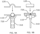
- FIG. 9 A shows a front view of the second portion of the coupler-journal being placed over torque tubes that are placed within the first portion of the coupler-journal that is connected with the lower bearing portion, according to some embodiments;
- FIG. 9 B shows a side view of the second portion of the coupler-journal being placed over torque tubes that are placed within the first portion of the coupler-journal that is connected with the lower bearing portion, according to some embodiments;
- FIG. 10 A shows a front view of the second portion of the coupler-journal securely connected with the first portion of the coupler-journal with the torque tubes placed between the first portion and the second portion of the coupler-journal, and the first portion of the journal-coupler is connected with the lower bearing portion, according to some embodiments;
- FIG. 10 B shows a side view of the second portion of the coupler-journal securely connected with the first portion of the coupler-journal with the torque tubes placed between the first portion and the second portion of the coupler-journal, and the first portion of the journal-coupler is connected with the lower bearing portion, according to some embodiments;
- FIG. 12 B shows a side view of an upper bearing portion securely connected to the bottom bearing portion, where the second portion of the coupler-journal is securely connected with the first portion of the coupler-journal with the torque tubes placed between the first portion and the second portion of the coupler-journal, and the first portion of the journal-coupler is connected with the lower bearing portion, according to some embodiments;
- FIG. 13 shows a perspective isolated view of the lower bearing portion, according to some embodiments.
- FIG. 14 A shows a front perspective isolated view of the upper bearing portion, according to some embodiments.
- FIG. 14 B shows a rear perspective isolated view of the upper bearing portion, according to some embodiments.
- the wall thickness is also sufficient enough to transfer the torque from one torque tube 720 to the next torque tube 720 .
- the outside round/circular bearing surface maximizes the surface contact to the bearing to minimize pressure at the bearing interfaces, and therefore minimizing wear on journal-coupler and the bearing, and therefore performing as the journal in a simple bearing system.
- FIG. 3 A shows a front view of the first portion 110 of the coupler-journal being placed into the lower bearing portion 310 , according to some embodiments.
- FIG. 3 B shows a side view of the first portion 110 of the coupler-journal being placed into the lower bearing portion 310 , according to some embodiments.
- the first portion 110 of a coupler-journal half with its faceted concave inner surface facing up being lowered in the direction of the arrow into the semi-circular bearing surface of the lower bearing portion 310 .
- the round outer surface of the body of the first portion 110 of the coupler-journal mates with, sits and rotates against the round bearing surface of the lower bearing portion 310 .
- FIG. 5 B shows a front view of the first portion 110 of the coupler-journal coupled with the lower bearing portion 310 , according to some embodiments.
- FIG. 5 C shows a side view of the first portion 110 of the coupler-journal coupled with the lower bearing portion 310 , according to some embodiments.
- the first portion 110 of the coupler-journal with its faceted concave interior surface facing up, is resting on the bearing surface of the lower bearing portion 310 .
- the upright prongs 311 and 312 are sized to both be equal with, lower than or above the first opening 111 and the second opening 112 .
- the upright prongs 311 and 312 remain in a fixed orientation and either pass above or below the respective first opening 111 and the second opening 112 depending on the amount of rotation of the first portion 110 .
- FIG. 6 shows a perspective view of the first portion 110 of the coupler-journal coupled with the lower bearing portion 310 , according to some embodiments. As shown, the lower portion 110 is rotated clockwise such that the upright prong 311 is oriented below the first opening 111 and the upright prong 312 is oriented above the second opening 112 .
- FIG. 7 A shows a front view of a torque tube 720 being placed into the first portion 110 of the coupler-journal that is connected with the lower bearing portion 310 , according to some embodiments.
- FIG. 7 B shows a side view of the torque tube 720 being placed into the first portion 110 of the coupler-journal that is connected with the lower bearing portion 310 , according to some embodiments.
- there are two end-to-end torque tubes 720 being lowered (in the direction of the arrows) into the faceted concave surface of the first portion 110 of the coupler-journal.
- the torque tubes 720 may be manually lowered into the first portion 110 by hand, by a lifting device, etc.
- FIG. 9 A shows a front view of the second portion 120 of the coupler-journal being placed over the torque tubes 720 that are placed within the first portion 110 of the coupler-journal that is connected with the lower bearing portion 310 , according to some embodiments.
- FIG. 9 B shows a side view of the second portion 120 of the coupler-journal being placed over the torque tubes 720 that are placed within the first portion 110 of the coupler-journal that is connected with the lower bearing portion 310 , according to some embodiments.
- the faceted concave surfaces of the first portion 110 and the second portion 120 are in alignment with the faceted surfaces of the torque tubes 720 to provide non-slip rotation of the torque tubes 720 .
- FIG. 10 A shows a front view of the second portion 120 of the coupler-journal securely connected with the first portion 110 of the coupler-journal with the torque tubes 720 placed between the first portion 110 and the second portion 120 of the coupler-journal, and the first portion 110 of the journal-coupler is connected with the lower bearing portion 310 , according to some embodiments.
- FIG. 10 B shows a side view of the second portion 120 of the coupler-journal securely connected with the first portion 110 of the coupler-journal with the torque tubes 720 placed between the first portion 110 and the second portion 120 of the coupler-journal, and the first portion 110 of the journal-coupler is connected with the lower bearing portion 310 , according to some embodiments.
- the wall thicknesses of the lower bearing portion 310 and the upper bearing portion 315 are thick enough to perform as a bearing race in a simple bearing system for the multi-decade life for which it is intended (e.g., performing as a simple bearing for a single axis tracker which will rotate back and forth daily for thirty years, constituting approximately twenty-two thousand turns).
- the wall thickness is also sufficient enough to hold the journal and hence the torque tubes 720 and solar panels in place when subjected to gravity forces and wind forces.
- 12 B shows a side view of the upper bearing portion 315 securely connected to the lower bearing portion 310 , where the second portion 120 of the coupler-journal is securely connected with the first portion 110 of the coupler-journal with the torque tubes 720 placed between the first portion 110 and the second portion 120 of the coupler-journal, and the first portion 110 of the coupler-journal is connected with the lower bearing portion 310 , according to some embodiments.
- the upper bearing portion 315 attached to the lower bearing portion 310 forms a fully circular bearing with a 360° round, smooth, and simple bearing surface.
- the formed bearing guides and retains the coupler-journal and hence the torque tubes 720 , forming a simple bearing.
- the simple bearing sustains loads from gravity, wind, and seismic forces that act on the torque tubes 720 , both as a directional force and as a torsional force.
- the simple bearing also forms an electrical ground path between the formed bearing and the coupler-journal via constant metal to metal contact and under continuous interface pressure of which undergoes daily surface-to-surface interface wiping from the two approximate ninety-degree rotations (90 degree turning during sun tracking and back-tracking, and 90 degree return turn) per day.
- FIG. 13 shows a perspective isolated view of the lower bearing portion 310 , according to some embodiments.
- the lower bearing portion 310 includes the upright prongs 311 and 312 , pier insert stops 313 and 314 , pier insert portion 316 and fastening slots 317 .
- the bearing surface forms a smooth semi-circle.
- the upright prongs 311 and 312 terminate with the latching portions 320 and 322 including through-holes to house, for example, fasteners, bolts/screws/etc., that captures the upper bearing portion 315 .
- FIG. 14 A shows a front perspective isolated view of the upper bearing portion 315 , according to some embodiments.
- the bearing surface 319 forms a smooth semi-circle.
- the two protruding flat flanges 321 and 323 at the bottom of the two ends of the upper bearing portion 315 are designed to slide into a capture feature of the latching portions 320 and 322 ( FIG. 13 ) of the lower bearing portion 310 .
- a gusset 325 FIG. 14 B
- a gusset 324 FIG.
- flange 323 is added (e.g., welded, formed/molded, fastened (e.g., screws, bolts, etc.)) to flange 323 to give additional strength to the flanges 321 and 323 when a pull force is applied to the upper bearing portion 315 . Only one gusset is attached per side to allow the bearing upper portion 315 to slide sideways into the latching portions 320 and 322 of the lower bearing portion 310 .
- FIG. 14 B shows a rear perspective isolated view of the upper bearing portion 315 , according to some embodiments.
- the gussets 324 and 235 help hold the two flanges 321 and 323 in place.
- FIG. 15 shows a combined perspective view of the upper bearing portion 315 and the lower bearing portion 310 , according to some embodiments.
- the upper bearing portion 315 and the lower bearing portion 310 are in a near-ready attachment position.
- the upper bearing portion 315 is lowered to the lower bearing portion 310 so that the two flanges 321 and 323 of the upper bearing portion 315 are just to the side of and in-line with the latching portions 320 and 322 of the lower bearing portion 310 , and then moved sideways in one direction only so that the two flanges 321 and 323 of the upper bearing portion 315 slide into the latching portions 322 and 320 , respectively, of the lower bearing portion 310 until the sliding action is stopped by the gussets 324 and 325 on the upper bearing portion 315 and the gussets 326 and 327 of the lower bearing portion 310 are positioned such that the fastening through-holes of both the upper bearing portion 315 and the lower bearing portion 310 are aligned.
- FIG. 16 shows a perspective view of the coupler-journal coupled with the upper bearing portion 315 securely connected to the lower bearing portion 310 that is connected to a pier 410 , according to some embodiments.
- the second portion 120 of the coupler-journal is securely connected with the first portion 110 of the coupler-journal, and the first portion 110 of the journal-coupler is connected with the lower bearing portion 310 .
- the pier 410 includes an upper pier portion 413 and coupling slots 417 .
- the upper pier portion 413 may contact the pier insert stops 313 and 314 ( FIG. 13 ), for example to provide clearance for rotation movement of the coupler-journal.
- the pier insert portion 316 is fastened using the coupling slots 417 aligned with fastening slots 317 using fasteners such as bolts and nuts, screws, welding, etc.
- the upper bearing portion 315 and the lower bearing portion 310 latch together to form one bearing housing.
- the latching portions 320 and 322 ( FIG. 13 ) of the bearing absorb all of the separation forces for keeping the major forces off of the fastening hardware.
- the bearing is a two-component (lower bearing portion 310 and the upper bearing portion 315 ) system by which a torque tube 720 (see, e.g., FIGS. 7 A-B - 12 A-B) or an axle may be lowered and quickly placed into the lower bearing portion 310 .
- the upper bearing portion 315 is then quickly attached to the lower bearing portion 310 .
- a fastener can then be dropped into place to aid in keeping the latching portions 320 and 322 of the bearing in alignment and in place.
- This latching is that there is no force, either in shear or in tension, on the fastener (e.g., a threaded bolt and nut hardware, etc.).
- Another advantage of the latching bearing system is that the mechanical parts of a single axis tracking system can be easily disassembled and reworked if needed simply by removing the upper bearing portion 315 of the bearing housing.
Landscapes
- Engineering & Computer Science (AREA)
- Mechanical Engineering (AREA)
- Life Sciences & Earth Sciences (AREA)
- Sustainable Development (AREA)
- Physics & Mathematics (AREA)
- Sustainable Energy (AREA)
- Thermal Sciences (AREA)
- Chemical & Material Sciences (AREA)
- Combustion & Propulsion (AREA)
- General Engineering & Computer Science (AREA)
- Sliding-Contact Bearings (AREA)
Abstract
Description
Claims (7)
Priority Applications (2)
| Application Number | Priority Date | Filing Date | Title |
|---|---|---|---|
| US17/549,567 US12180764B2 (en) | 2018-03-25 | 2021-12-13 | Bearing and coupler-journal devices for panels |
| US18/960,402 US20250084683A1 (en) | 2018-03-25 | 2024-11-26 | Bearing and coupler-journal devices for panels |
Applications Claiming Priority (4)
| Application Number | Priority Date | Filing Date | Title |
|---|---|---|---|
| US201862647778P | 2018-03-25 | 2018-03-25 | |
| US201862648546P | 2018-03-27 | 2018-03-27 | |
| US16/363,288 US11230866B2 (en) | 2018-03-25 | 2019-03-25 | Bearing and coupler-journal devices for panels |
| US17/549,567 US12180764B2 (en) | 2018-03-25 | 2021-12-13 | Bearing and coupler-journal devices for panels |
Related Parent Applications (1)
| Application Number | Title | Priority Date | Filing Date |
|---|---|---|---|
| US16/363,288 Continuation US11230866B2 (en) | 2018-03-25 | 2019-03-25 | Bearing and coupler-journal devices for panels |
Related Child Applications (1)
| Application Number | Title | Priority Date | Filing Date |
|---|---|---|---|
| US18/960,402 Continuation US20250084683A1 (en) | 2018-03-25 | 2024-11-26 | Bearing and coupler-journal devices for panels |
Publications (2)
| Publication Number | Publication Date |
|---|---|
| US20220098909A1 US20220098909A1 (en) | 2022-03-31 |
| US12180764B2 true US12180764B2 (en) | 2024-12-31 |
Family
ID=67983499
Family Applications (3)
| Application Number | Title | Priority Date | Filing Date |
|---|---|---|---|
| US16/363,288 Active US11230866B2 (en) | 2018-03-25 | 2019-03-25 | Bearing and coupler-journal devices for panels |
| US17/549,567 Active US12180764B2 (en) | 2018-03-25 | 2021-12-13 | Bearing and coupler-journal devices for panels |
| US18/960,402 Pending US20250084683A1 (en) | 2018-03-25 | 2024-11-26 | Bearing and coupler-journal devices for panels |
Family Applications Before (1)
| Application Number | Title | Priority Date | Filing Date |
|---|---|---|---|
| US16/363,288 Active US11230866B2 (en) | 2018-03-25 | 2019-03-25 | Bearing and coupler-journal devices for panels |
Family Applications After (1)
| Application Number | Title | Priority Date | Filing Date |
|---|---|---|---|
| US18/960,402 Pending US20250084683A1 (en) | 2018-03-25 | 2024-11-26 | Bearing and coupler-journal devices for panels |
Country Status (1)
| Country | Link |
|---|---|
| US (3) | US11230866B2 (en) |
Families Citing this family (12)
| Publication number | Priority date | Publication date | Assignee | Title |
|---|---|---|---|---|
| US10008975B2 (en) | 2012-12-10 | 2018-06-26 | Nextracker Inc. | Clamp assembly for solar tracker |
| US9766319B2 (en) | 2012-12-10 | 2017-09-19 | Nextracker Inc. | Off-set drive assembly for solar tracker |
| US9466749B1 (en) * | 2012-12-10 | 2016-10-11 | Nextracker Inc. | Balanced solar tracker clamp |
| DE112013005890T5 (en) | 2012-12-10 | 2015-09-10 | Nextracker Inc. | Horizontal balanced solar flatfighter |
| US11802591B2 (en) | 2018-03-26 | 2023-10-31 | Sun And Steel Solar Llc | Journal-coupler for joining panel torque tubes |
| US10845092B2 (en) * | 2018-09-19 | 2020-11-24 | Robert B. Dally | Panel mounting components |
| US11569780B2 (en) * | 2020-03-17 | 2023-01-31 | Sun And Steel Solar Llc | Purlin system for solar module attachment |
| US11863118B2 (en) | 2020-12-22 | 2024-01-02 | Sun And Steel Solar Llc | Bearing system for solar tracker |
| WO2022221868A1 (en) | 2021-04-16 | 2022-10-20 | Saint-Gobain Performance Plastics Corporation | Bearing assembly for tracker assembly and methods of making and using the same |
| US20230141013A1 (en) * | 2021-11-09 | 2023-05-11 | Saint-Gobain Performance Plastics Pampus Gmbh | Bearing assembly for tracker assembly and methods of making and using the same |
| US11946587B2 (en) * | 2022-03-01 | 2024-04-02 | Sun And Steel Solar Llc | Simple bearing for solar tracking |
| US20250055410A1 (en) * | 2023-08-09 | 2025-02-13 | Sun And Steel Solar Llc | Simple bearing for solar tracking |
Citations (60)
| Publication number | Priority date | Publication date | Assignee | Title |
|---|---|---|---|---|
| US2380952A (en) | 1943-06-23 | 1945-08-07 | Clarence L Dewey | Propeller shaft |
| US2425033A (en) * | 1944-06-06 | 1947-08-05 | Wendell S Fletcher | Clamping device |
| US3048177A (en) | 1959-06-23 | 1962-08-07 | Takaro Timothy | Blood vessel coupling device |
| US3227406A (en) | 1963-07-15 | 1966-01-04 | North American Aviation Inc | High temperature clamp and method of making same |
| US3554306A (en) | 1968-11-29 | 1971-01-12 | Carmet Co | Polygonal drill rod assembly |
| US4085816A (en) * | 1975-04-04 | 1978-04-25 | Nissan Motor Co., Ltd. | Heat shield for an exhaust tail pipe |
| DE3827662A1 (en) | 1988-03-23 | 1990-02-22 | Korff & Co | Multiple-part pipe clamp |
| US5320579A (en) | 1990-06-23 | 1994-06-14 | Gkn Automotive Ag | Energy absorbing driveshaft connections |
| US5540465A (en) | 1994-08-01 | 1996-07-30 | Sisk; David E. | Pipe, valve and/or tee coupler |
| US6305719B1 (en) | 1998-10-30 | 2001-10-23 | Laurence S. Smith, Jr. | Pipe repair clamp |
| US6370756B1 (en) | 2000-05-17 | 2002-04-16 | Caraustar Industrial & Consumer Products Group | Method of forming damped drive shafts |
| US6484384B1 (en) | 1998-12-31 | 2002-11-26 | Spicer Driveshaft, Inc. | Method of manufacturing an axially collapsible driveshaft assembly |
| US6520710B2 (en) * | 2001-02-14 | 2003-02-18 | Delphi Technologies, Inc. | Powdered metal assemblies with fastener inserts |
| US20030106968A1 (en) * | 2001-12-07 | 2003-06-12 | George Terrill | Exhaust system tool and method for use thereof |
| US6775890B2 (en) * | 2000-09-25 | 2004-08-17 | Frank Kolarik | Apparatus for urging two members apart or together |
| US20070256288A1 (en) * | 1999-11-03 | 2007-11-08 | Vermaat Technics B.V.. | Method and device for welding pipes |
| US7350834B2 (en) * | 2002-03-04 | 2008-04-01 | Norma Sweden Ab | Coupling device constitute two halves |
| US7665773B2 (en) * | 2006-06-21 | 2010-02-23 | Conocophillips Company | Self-tightening clamp assemblies for protection against full pipe separation |
| US20100139646A1 (en) * | 2009-02-02 | 2010-06-10 | Sunpower Corporation | Torque Arm Assembly and Method |
| KR20110048497A (en) | 2011-04-14 | 2011-05-11 | 오쏠라 유한회사 | Solar power generation device |
| US20110253195A1 (en) * | 2010-04-19 | 2011-10-20 | Youil Ensys Co., Ltd. | Torque tube supporter and solar tracker using the same |
| CA2813917A1 (en) | 2010-10-26 | 2012-05-03 | Keisuke Minami | Tube support structure for aircraft |
| US8192210B2 (en) * | 2010-04-06 | 2012-06-05 | Halex Co./a Scott-Fetzer Company | Ground clamp kit |
| US8230883B2 (en) | 2006-12-01 | 2012-07-31 | Toyota Jidosha Kabushiki Kaisha | Gas piping system for fuel cell |
| US8317526B2 (en) * | 2009-04-14 | 2012-11-27 | Halex Co. | Ground clamp |
| US20130039610A1 (en) * | 2011-08-12 | 2013-02-14 | Matthew Schneider | Solar tracking bearing and solar tracking system employing same |
| US20130048798A1 (en) | 2011-08-26 | 2013-02-28 | Michael E. Bock | Pipe Anchor |
| US20130118627A1 (en) * | 2011-11-14 | 2013-05-16 | United Technologies Corporation | Tuned response duct clamp |
| US8449308B2 (en) * | 2010-10-07 | 2013-05-28 | Bridgeport Fittings, Inc. | Electric ground clamp with pivoted jaws and single attached adjusting bolt and terminal block |
| CN103727313A (en) | 2014-01-23 | 2014-04-16 | 黄晓峰 | Plastic bracket of water dividing and collecting device |
| EP2730830A1 (en) | 2012-12-11 | 2014-05-14 | Jian Wu | Pipe pre-fixing sound-insulating clamp |
| US8864504B1 (en) * | 2012-06-10 | 2014-10-21 | Arlington Industries, Inc. | Intersystem grounding clamp with serrated gripping surfaces and a plurality of grounding terminals |
| US8864182B2 (en) * | 2012-08-10 | 2014-10-21 | Jackie Ray Buchanan | Coupling device |
| US20140346291A1 (en) * | 2013-05-22 | 2014-11-27 | Ellis Patents Holdings Limited | Cable guidance system |
| US20150001356A1 (en) * | 2012-12-10 | 2015-01-01 | Nextracker Inc. | Clamp assembly for solar tracker |
| US9038968B2 (en) | 2009-06-09 | 2015-05-26 | John HENNON | Attachable grommets for hanging pipes |
| US20150174706A1 (en) * | 2013-12-19 | 2015-06-25 | Mathew W. McClure | Apparatus for aligning sections of pipe |
| US9109408B2 (en) | 2011-11-08 | 2015-08-18 | Great Industries, Inc. | Drill members for mine roofs |
| US9303684B2 (en) | 2012-11-22 | 2016-04-05 | Grupo Clavijio Elt, S.L. | Swivel mount for solar tracker shafts |
| US20160123383A1 (en) * | 2014-11-03 | 2016-05-05 | First Solar, Inc. | Mounting device for a photovoltaic module |
| US9567811B2 (en) | 2013-09-17 | 2017-02-14 | Kennametal Inc. | Coupler for a rotatable cutter assembly |
| US20170108145A1 (en) | 2015-10-16 | 2017-04-20 | Airbus Operations Sas | Support for a conduit |
| US20170229998A1 (en) * | 2016-02-05 | 2017-08-10 | Solarcity Corporation | Pile cap with integrated bearing housing |
| US9806669B2 (en) * | 2014-11-05 | 2017-10-31 | Optimum Tracker | Single-axis follower support system for a solar collector |
| US20170317641A1 (en) | 2014-11-21 | 2017-11-02 | Raipro Gmbh | Bearing shaft for photovoltaic modules and system having a number of photovoltaic modules |
| US20180062563A1 (en) | 2016-09-01 | 2018-03-01 | Sunpower Corporation | Torque tube coupler |
| US20180062565A1 (en) * | 2016-09-01 | 2018-03-01 | Sunpower Corporation | Photovoltaic system bearing assembly |
| US20190068112A1 (en) * | 2017-08-31 | 2019-02-28 | QuantPower | Tracker system |
| US20190158017A1 (en) | 2017-08-31 | 2019-05-23 | QuantPower, Inc. | Tracker System with Bridge |
| EP3537019A1 (en) | 2018-03-07 | 2019-09-11 | Walter Stauffenberg Gmbh & Co. Kg | Device for the fixing of lines |
| US20190292824A1 (en) * | 2018-03-26 | 2019-09-26 | Robert B. Dally | Journal-coupler for joining panel torque tubes |
| EP3406952B1 (en) | 2017-05-22 | 2019-11-06 | HILTI Aktiengesellschaft | Pivotable cable holder |
| US20200010037A1 (en) | 2018-07-03 | 2020-01-09 | Caterpillar Inc. | Hydraulic hose clamp assembly |
| US10557588B2 (en) | 2014-03-27 | 2020-02-11 | Krausz Industries Ltd. | Pipe repair fitting with end seals |
| US20200076354A1 (en) * | 2018-09-05 | 2020-03-05 | Ojjo, Inc. | Optimized truss foundations, adapters for optimized truss foundations, and related systems and methods |
| US10584902B2 (en) * | 2017-05-31 | 2020-03-10 | Soltec Energias Renovables, S.L. | Support device for a rotating shaft of a solar tracker |
| US20200088446A1 (en) * | 2018-09-19 | 2020-03-19 | Robert B. Dally | Panel mounting components |
| US20200248930A1 (en) * | 2019-01-31 | 2020-08-06 | Barry Jon Kimble | Method and apparatus for mounting panels |
| US10859122B2 (en) | 2017-08-25 | 2020-12-08 | Kennametal Inc. | Spline drive drill steel couplers |
| US20220200520A1 (en) * | 2020-12-22 | 2022-06-23 | Sun And Steel Solar Llc | Bearing system for solar tracker |
Family Cites Families (2)
| Publication number | Priority date | Publication date | Assignee | Title |
|---|---|---|---|---|
| US6234541B1 (en) * | 1998-02-18 | 2001-05-22 | Donaldson Company, Inc. | U-bolt clamp for sealing lap joints |
| JP2948804B1 (en) * | 1998-04-16 | 1999-09-13 | 嘉作 鎌田 | Tightening method for piping |
-
2019
- 2019-03-25 US US16/363,288 patent/US11230866B2/en active Active
-
2021
- 2021-12-13 US US17/549,567 patent/US12180764B2/en active Active
-
2024
- 2024-11-26 US US18/960,402 patent/US20250084683A1/en active Pending
Patent Citations (63)
| Publication number | Priority date | Publication date | Assignee | Title |
|---|---|---|---|---|
| US2380952A (en) | 1943-06-23 | 1945-08-07 | Clarence L Dewey | Propeller shaft |
| US2425033A (en) * | 1944-06-06 | 1947-08-05 | Wendell S Fletcher | Clamping device |
| US3048177A (en) | 1959-06-23 | 1962-08-07 | Takaro Timothy | Blood vessel coupling device |
| US3227406A (en) | 1963-07-15 | 1966-01-04 | North American Aviation Inc | High temperature clamp and method of making same |
| US3554306A (en) | 1968-11-29 | 1971-01-12 | Carmet Co | Polygonal drill rod assembly |
| US4085816A (en) * | 1975-04-04 | 1978-04-25 | Nissan Motor Co., Ltd. | Heat shield for an exhaust tail pipe |
| DE3827662A1 (en) | 1988-03-23 | 1990-02-22 | Korff & Co | Multiple-part pipe clamp |
| US5320579A (en) | 1990-06-23 | 1994-06-14 | Gkn Automotive Ag | Energy absorbing driveshaft connections |
| US5540465A (en) | 1994-08-01 | 1996-07-30 | Sisk; David E. | Pipe, valve and/or tee coupler |
| US6305719B1 (en) | 1998-10-30 | 2001-10-23 | Laurence S. Smith, Jr. | Pipe repair clamp |
| US6484384B1 (en) | 1998-12-31 | 2002-11-26 | Spicer Driveshaft, Inc. | Method of manufacturing an axially collapsible driveshaft assembly |
| US20070256288A1 (en) * | 1999-11-03 | 2007-11-08 | Vermaat Technics B.V.. | Method and device for welding pipes |
| US6370756B1 (en) | 2000-05-17 | 2002-04-16 | Caraustar Industrial & Consumer Products Group | Method of forming damped drive shafts |
| US6775890B2 (en) * | 2000-09-25 | 2004-08-17 | Frank Kolarik | Apparatus for urging two members apart or together |
| US6520710B2 (en) * | 2001-02-14 | 2003-02-18 | Delphi Technologies, Inc. | Powdered metal assemblies with fastener inserts |
| US20030106968A1 (en) * | 2001-12-07 | 2003-06-12 | George Terrill | Exhaust system tool and method for use thereof |
| US7350834B2 (en) * | 2002-03-04 | 2008-04-01 | Norma Sweden Ab | Coupling device constitute two halves |
| US7665773B2 (en) * | 2006-06-21 | 2010-02-23 | Conocophillips Company | Self-tightening clamp assemblies for protection against full pipe separation |
| US8230883B2 (en) | 2006-12-01 | 2012-07-31 | Toyota Jidosha Kabushiki Kaisha | Gas piping system for fuel cell |
| US20100139646A1 (en) * | 2009-02-02 | 2010-06-10 | Sunpower Corporation | Torque Arm Assembly and Method |
| US8317526B2 (en) * | 2009-04-14 | 2012-11-27 | Halex Co. | Ground clamp |
| US9038968B2 (en) | 2009-06-09 | 2015-05-26 | John HENNON | Attachable grommets for hanging pipes |
| US8192210B2 (en) * | 2010-04-06 | 2012-06-05 | Halex Co./a Scott-Fetzer Company | Ground clamp kit |
| US20110253195A1 (en) * | 2010-04-19 | 2011-10-20 | Youil Ensys Co., Ltd. | Torque tube supporter and solar tracker using the same |
| US8449308B2 (en) * | 2010-10-07 | 2013-05-28 | Bridgeport Fittings, Inc. | Electric ground clamp with pivoted jaws and single attached adjusting bolt and terminal block |
| CA2813917A1 (en) | 2010-10-26 | 2012-05-03 | Keisuke Minami | Tube support structure for aircraft |
| KR20110048497A (en) | 2011-04-14 | 2011-05-11 | 오쏠라 유한회사 | Solar power generation device |
| US20130039610A1 (en) * | 2011-08-12 | 2013-02-14 | Matthew Schneider | Solar tracking bearing and solar tracking system employing same |
| US20130048798A1 (en) | 2011-08-26 | 2013-02-28 | Michael E. Bock | Pipe Anchor |
| US9109408B2 (en) | 2011-11-08 | 2015-08-18 | Great Industries, Inc. | Drill members for mine roofs |
| US20130118627A1 (en) * | 2011-11-14 | 2013-05-16 | United Technologies Corporation | Tuned response duct clamp |
| US8864504B1 (en) * | 2012-06-10 | 2014-10-21 | Arlington Industries, Inc. | Intersystem grounding clamp with serrated gripping surfaces and a plurality of grounding terminals |
| US8864182B2 (en) * | 2012-08-10 | 2014-10-21 | Jackie Ray Buchanan | Coupling device |
| US9303684B2 (en) | 2012-11-22 | 2016-04-05 | Grupo Clavijio Elt, S.L. | Swivel mount for solar tracker shafts |
| US20150001356A1 (en) * | 2012-12-10 | 2015-01-01 | Nextracker Inc. | Clamp assembly for solar tracker |
| EP2730830A1 (en) | 2012-12-11 | 2014-05-14 | Jian Wu | Pipe pre-fixing sound-insulating clamp |
| US20140346291A1 (en) * | 2013-05-22 | 2014-11-27 | Ellis Patents Holdings Limited | Cable guidance system |
| US9567811B2 (en) | 2013-09-17 | 2017-02-14 | Kennametal Inc. | Coupler for a rotatable cutter assembly |
| US20150174706A1 (en) * | 2013-12-19 | 2015-06-25 | Mathew W. McClure | Apparatus for aligning sections of pipe |
| US9808893B2 (en) * | 2013-12-19 | 2017-11-07 | Walhonde Tools Inc. | Apparatus for aligning sections of pipe |
| CN103727313A (en) | 2014-01-23 | 2014-04-16 | 黄晓峰 | Plastic bracket of water dividing and collecting device |
| US10557588B2 (en) | 2014-03-27 | 2020-02-11 | Krausz Industries Ltd. | Pipe repair fitting with end seals |
| US20160123383A1 (en) * | 2014-11-03 | 2016-05-05 | First Solar, Inc. | Mounting device for a photovoltaic module |
| US9806669B2 (en) * | 2014-11-05 | 2017-10-31 | Optimum Tracker | Single-axis follower support system for a solar collector |
| US20170317641A1 (en) | 2014-11-21 | 2017-11-02 | Raipro Gmbh | Bearing shaft for photovoltaic modules and system having a number of photovoltaic modules |
| US20170108145A1 (en) | 2015-10-16 | 2017-04-20 | Airbus Operations Sas | Support for a conduit |
| US20180023729A1 (en) | 2015-10-16 | 2018-01-25 | Airbus Operations (S.A.S.). | Support for a pipe |
| US20170229998A1 (en) * | 2016-02-05 | 2017-08-10 | Solarcity Corporation | Pile cap with integrated bearing housing |
| US20180062565A1 (en) * | 2016-09-01 | 2018-03-01 | Sunpower Corporation | Photovoltaic system bearing assembly |
| US20180062563A1 (en) | 2016-09-01 | 2018-03-01 | Sunpower Corporation | Torque tube coupler |
| US10320326B2 (en) | 2016-09-01 | 2019-06-11 | Sunpower Corporation | Photovoltaic system bearing assembly |
| EP3406952B1 (en) | 2017-05-22 | 2019-11-06 | HILTI Aktiengesellschaft | Pivotable cable holder |
| US10584902B2 (en) * | 2017-05-31 | 2020-03-10 | Soltec Energias Renovables, S.L. | Support device for a rotating shaft of a solar tracker |
| US10859122B2 (en) | 2017-08-25 | 2020-12-08 | Kennametal Inc. | Spline drive drill steel couplers |
| US20190158017A1 (en) | 2017-08-31 | 2019-05-23 | QuantPower, Inc. | Tracker System with Bridge |
| US20190068112A1 (en) * | 2017-08-31 | 2019-02-28 | QuantPower | Tracker system |
| EP3537019A1 (en) | 2018-03-07 | 2019-09-11 | Walter Stauffenberg Gmbh & Co. Kg | Device for the fixing of lines |
| US20190292824A1 (en) * | 2018-03-26 | 2019-09-26 | Robert B. Dally | Journal-coupler for joining panel torque tubes |
| US20200010037A1 (en) | 2018-07-03 | 2020-01-09 | Caterpillar Inc. | Hydraulic hose clamp assembly |
| US20200076354A1 (en) * | 2018-09-05 | 2020-03-05 | Ojjo, Inc. | Optimized truss foundations, adapters for optimized truss foundations, and related systems and methods |
| US20200088446A1 (en) * | 2018-09-19 | 2020-03-19 | Robert B. Dally | Panel mounting components |
| US20200248930A1 (en) * | 2019-01-31 | 2020-08-06 | Barry Jon Kimble | Method and apparatus for mounting panels |
| US20220200520A1 (en) * | 2020-12-22 | 2022-06-23 | Sun And Steel Solar Llc | Bearing system for solar tracker |
Non-Patent Citations (11)
| Title |
|---|
| U.S. Advisory Action for U.S. Appl. No. 16/363,288 mailed Nov. 20, 2020. |
| U.S. Advisory Action for U.S. Appl. No. 16/363,303 mailed Nov. 3, 2022. |
| U.S. Corrected Notice of Allowability for U.S. Appl. No. 16/363,288 mailed Sep. 17, 2021. |
| U.S. Final Office Action for U.S. Appl. No. 16/363,288 mailed Sep. 17, 2020. |
| U.S. Final Office Action for U.S. Appl. No. 16/363,303 mailed Apr. 24, 2023. |
| U.S. Final Office Action for U.S. Appl. No. 16/363,303 mailed Aug. 26, 2022. |
| U.S. Non-Final Office Action for U.S. Appl. No. 16/363,288 mailed May 13, 2021. |
| U.S. Non-Final Office Action for U.S. Appl. No. 16/363,303 mailed Apr. 22, 2022. |
| U.S. Non-Final Office Action for U.S. Appl. No. 16/363,303 mailed Jan. 13, 2023. |
| U.S. Notice of Allowance for U.S. Appl. No. 16/363,288 mailed Sep. 14, 2021. |
| U.S. Notice of Allowance for U.S. Appl. No. 16/363,303 mailed Jun. 15, 2023. |
Also Published As
| Publication number | Publication date |
|---|---|
| US20250084683A1 (en) | 2025-03-13 |
| US20220098909A1 (en) | 2022-03-31 |
| US11230866B2 (en) | 2022-01-25 |
| US20190292823A1 (en) | 2019-09-26 |
Similar Documents
| Publication | Publication Date | Title |
|---|---|---|
| US12180764B2 (en) | Bearing and coupler-journal devices for panels | |
| US11802591B2 (en) | Journal-coupler for joining panel torque tubes | |
| US11835266B2 (en) | Panel mounting components | |
| US20220276331A1 (en) | Off-set drive assembly for solar tracker | |
| CN103178139B (en) | Supports for solar collectors | |
| JP5958941B2 (en) | Support for solar energy concentrator | |
| EP3009766B1 (en) | Solar tracking system | |
| JP7118005B2 (en) | Mounting bracket assembly and method | |
| US20250092678A1 (en) | Truss foundation adapters for single-axis trackers | |
| US20230114763A1 (en) | Mounting bracket extension | |
| US7964983B2 (en) | Retrofittable wind powered electric generator | |
| US20130074831A1 (en) | Torque transfer between trough collector modules | |
| US20200052644A1 (en) | Variable terrain solar tracker | |
| US20160285411A1 (en) | Solar Tracking Panel Mount | |
| EP2317247A2 (en) | Photovoltaic solar tracker | |
| JP2019504979A (en) | Adjustable support | |
| US9182030B2 (en) | Slew drive gearbox with spherical adjusting mount | |
| WO2019043612A1 (en) | A solar tracking displacement apparatus | |
| WO2018048890A1 (en) | Heliostat mirror panels with pivotable hardware modules | |
| US20250219378A1 (en) | Extension members and methods of use | |
| WO2024167858A1 (en) | Variable terrain solar tracker | |
| US20250233543A1 (en) | Self-closing photovoltaic module-to-torque tube rail | |
| US6227749B1 (en) | Swivel base assembly for connecting insulator to support structure | |
| US20250239963A1 (en) | Support structure for solar trackers with thermal expansion mitigation | |
| TWI680267B (en) | Binding assembly for supporting frame of solar power generation device |
Legal Events
| Date | Code | Title | Description |
|---|---|---|---|
| AS | Assignment |
Owner name: SUN AND STEEL SOLAR LLC, NEVADA Free format text: ASSIGNMENT OF ASSIGNORS INTEREST;ASSIGNOR:DALLY, ROBERT B.;REEL/FRAME:058376/0071 Effective date: 20211201 |
|
| FEPP | Fee payment procedure |
Free format text: ENTITY STATUS SET TO UNDISCOUNTED (ORIGINAL EVENT CODE: BIG.); ENTITY STATUS OF PATENT OWNER: SMALL ENTITY |
|
| FEPP | Fee payment procedure |
Free format text: ENTITY STATUS SET TO SMALL (ORIGINAL EVENT CODE: SMAL); ENTITY STATUS OF PATENT OWNER: SMALL ENTITY |
|
| STPP | Information on status: patent application and granting procedure in general |
Free format text: DOCKETED NEW CASE - READY FOR EXAMINATION |
|
| STPP | Information on status: patent application and granting procedure in general |
Free format text: RESPONSE TO NON-FINAL OFFICE ACTION ENTERED AND FORWARDED TO EXAMINER |
|
| STPP | Information on status: patent application and granting procedure in general |
Free format text: NON FINAL ACTION MAILED |
|
| STPP | Information on status: patent application and granting procedure in general |
Free format text: RESPONSE TO NON-FINAL OFFICE ACTION ENTERED AND FORWARDED TO EXAMINER |
|
| STPP | Information on status: patent application and granting procedure in general |
Free format text: FINAL REJECTION MAILED |
|
| STPP | Information on status: patent application and granting procedure in general |
Free format text: RESPONSE AFTER FINAL ACTION FORWARDED TO EXAMINER |
|
| STPP | Information on status: patent application and granting procedure in general |
Free format text: ADVISORY ACTION MAILED |
|
| STPP | Information on status: patent application and granting procedure in general |
Free format text: RESPONSE AFTER FINAL ACTION FORWARDED TO EXAMINER |
|
| STPP | Information on status: patent application and granting procedure in general |
Free format text: NOTICE OF ALLOWANCE MAILED -- APPLICATION RECEIVED IN OFFICE OF PUBLICATIONS |
|
| STPP | Information on status: patent application and granting procedure in general |
Free format text: PUBLICATIONS -- ISSUE FEE PAYMENT RECEIVED |
|
| STPP | Information on status: patent application and granting procedure in general |
Free format text: PUBLICATIONS -- ISSUE FEE PAYMENT VERIFIED |
|
| STCF | Information on status: patent grant |
Free format text: PATENTED CASE |