US12180456B2 - Tissue healing - Google Patents
Tissue healing Download PDFInfo
- Publication number
- US12180456B2 US12180456B2 US18/395,415 US202318395415A US12180456B2 US 12180456 B2 US12180456 B2 US 12180456B2 US 202318395415 A US202318395415 A US 202318395415A US 12180456 B2 US12180456 B2 US 12180456B2
- Authority
- US
- United States
- Prior art keywords
- pestle
- well
- cup
- tissue
- mortar
- Prior art date
- Legal status (The legal status is an assumption and is not a legal conclusion. Google has not performed a legal analysis and makes no representation as to the accuracy of the status listed.)
- Active
Links
Images


Classifications
-
- C—CHEMISTRY; METALLURGY
- C12—BIOCHEMISTRY; BEER; SPIRITS; WINE; VINEGAR; MICROBIOLOGY; ENZYMOLOGY; MUTATION OR GENETIC ENGINEERING
- C12M—APPARATUS FOR ENZYMOLOGY OR MICROBIOLOGY; APPARATUS FOR CULTURING MICROORGANISMS FOR PRODUCING BIOMASS, FOR GROWING CELLS OR FOR OBTAINING FERMENTATION OR METABOLIC PRODUCTS, i.e. BIOREACTORS OR FERMENTERS
- C12M41/00—Means for regulation, monitoring, measurement or control, e.g. flow regulation
- C12M41/48—Automatic or computerized control
-
- C—CHEMISTRY; METALLURGY
- C12—BIOCHEMISTRY; BEER; SPIRITS; WINE; VINEGAR; MICROBIOLOGY; ENZYMOLOGY; MUTATION OR GENETIC ENGINEERING
- C12M—APPARATUS FOR ENZYMOLOGY OR MICROBIOLOGY; APPARATUS FOR CULTURING MICROORGANISMS FOR PRODUCING BIOMASS, FOR GROWING CELLS OR FOR OBTAINING FERMENTATION OR METABOLIC PRODUCTS, i.e. BIOREACTORS OR FERMENTERS
- C12M45/00—Means for pre-treatment of biological substances
- C12M45/02—Means for pre-treatment of biological substances by mechanical forces; Stirring; Trituration; Comminuting
-
- B—PERFORMING OPERATIONS; TRANSPORTING
- B01—PHYSICAL OR CHEMICAL PROCESSES OR APPARATUS IN GENERAL
- B01L—CHEMICAL OR PHYSICAL LABORATORY APPARATUS FOR GENERAL USE
- B01L3/00—Containers or dishes for laboratory use, e.g. laboratory glassware; Droppers
- B01L3/50—Containers for the purpose of retaining a material to be analysed, e.g. test tubes
- B01L3/502—Containers for the purpose of retaining a material to be analysed, e.g. test tubes with fluid transport, e.g. in multi-compartment structures
- B01L3/5025—Containers for the purpose of retaining a material to be analysed, e.g. test tubes with fluid transport, e.g. in multi-compartment structures for parallel transport of multiple samples
- B01L3/50255—Multi-well filtration
-
- C—CHEMISTRY; METALLURGY
- C12—BIOCHEMISTRY; BEER; SPIRITS; WINE; VINEGAR; MICROBIOLOGY; ENZYMOLOGY; MUTATION OR GENETIC ENGINEERING
- C12M—APPARATUS FOR ENZYMOLOGY OR MICROBIOLOGY; APPARATUS FOR CULTURING MICROORGANISMS FOR PRODUCING BIOMASS, FOR GROWING CELLS OR FOR OBTAINING FERMENTATION OR METABOLIC PRODUCTS, i.e. BIOREACTORS OR FERMENTERS
- C12M21/00—Bioreactors or fermenters specially adapted for specific uses
- C12M21/08—Bioreactors or fermenters specially adapted for specific uses for producing artificial tissue or for ex-vivo cultivation of tissue
-
- C—CHEMISTRY; METALLURGY
- C12—BIOCHEMISTRY; BEER; SPIRITS; WINE; VINEGAR; MICROBIOLOGY; ENZYMOLOGY; MUTATION OR GENETIC ENGINEERING
- C12M—APPARATUS FOR ENZYMOLOGY OR MICROBIOLOGY; APPARATUS FOR CULTURING MICROORGANISMS FOR PRODUCING BIOMASS, FOR GROWING CELLS OR FOR OBTAINING FERMENTATION OR METABOLIC PRODUCTS, i.e. BIOREACTORS OR FERMENTERS
- C12M23/00—Constructional details, e.g. recesses, hinges
- C12M23/02—Form or structure of the vessel
- C12M23/12—Well or multiwell plates
-
- C—CHEMISTRY; METALLURGY
- C12—BIOCHEMISTRY; BEER; SPIRITS; WINE; VINEGAR; MICROBIOLOGY; ENZYMOLOGY; MUTATION OR GENETIC ENGINEERING
- C12M—APPARATUS FOR ENZYMOLOGY OR MICROBIOLOGY; APPARATUS FOR CULTURING MICROORGANISMS FOR PRODUCING BIOMASS, FOR GROWING CELLS OR FOR OBTAINING FERMENTATION OR METABOLIC PRODUCTS, i.e. BIOREACTORS OR FERMENTERS
- C12M23/00—Constructional details, e.g. recesses, hinges
- C12M23/38—Caps; Covers; Plugs; Pouring means
-
- C—CHEMISTRY; METALLURGY
- C12—BIOCHEMISTRY; BEER; SPIRITS; WINE; VINEGAR; MICROBIOLOGY; ENZYMOLOGY; MUTATION OR GENETIC ENGINEERING
- C12M—APPARATUS FOR ENZYMOLOGY OR MICROBIOLOGY; APPARATUS FOR CULTURING MICROORGANISMS FOR PRODUCING BIOMASS, FOR GROWING CELLS OR FOR OBTAINING FERMENTATION OR METABOLIC PRODUCTS, i.e. BIOREACTORS OR FERMENTERS
- C12M23/00—Constructional details, e.g. recesses, hinges
- C12M23/42—Integrated assemblies, e.g. cassettes or cartridges
-
- C—CHEMISTRY; METALLURGY
- C12—BIOCHEMISTRY; BEER; SPIRITS; WINE; VINEGAR; MICROBIOLOGY; ENZYMOLOGY; MUTATION OR GENETIC ENGINEERING
- C12M—APPARATUS FOR ENZYMOLOGY OR MICROBIOLOGY; APPARATUS FOR CULTURING MICROORGANISMS FOR PRODUCING BIOMASS, FOR GROWING CELLS OR FOR OBTAINING FERMENTATION OR METABOLIC PRODUCTS, i.e. BIOREACTORS OR FERMENTERS
- C12M23/00—Constructional details, e.g. recesses, hinges
- C12M23/50—Means for positioning or orientating the apparatus
-
- C—CHEMISTRY; METALLURGY
- C12—BIOCHEMISTRY; BEER; SPIRITS; WINE; VINEGAR; MICROBIOLOGY; ENZYMOLOGY; MUTATION OR GENETIC ENGINEERING
- C12M—APPARATUS FOR ENZYMOLOGY OR MICROBIOLOGY; APPARATUS FOR CULTURING MICROORGANISMS FOR PRODUCING BIOMASS, FOR GROWING CELLS OR FOR OBTAINING FERMENTATION OR METABOLIC PRODUCTS, i.e. BIOREACTORS OR FERMENTERS
- C12M25/00—Means for supporting, enclosing or fixing the microorganisms, e.g. immunocoatings
- C12M25/02—Membranes; Filters
- C12M25/04—Membranes; Filters in combination with well or multiwell plates, i.e. culture inserts
-
- C—CHEMISTRY; METALLURGY
- C12—BIOCHEMISTRY; BEER; SPIRITS; WINE; VINEGAR; MICROBIOLOGY; ENZYMOLOGY; MUTATION OR GENETIC ENGINEERING
- C12M—APPARATUS FOR ENZYMOLOGY OR MICROBIOLOGY; APPARATUS FOR CULTURING MICROORGANISMS FOR PRODUCING BIOMASS, FOR GROWING CELLS OR FOR OBTAINING FERMENTATION OR METABOLIC PRODUCTS, i.e. BIOREACTORS OR FERMENTERS
- C12M27/00—Means for mixing, agitating or circulating fluids in the vessel
- C12M27/10—Rotating vessel
-
- C—CHEMISTRY; METALLURGY
- C12—BIOCHEMISTRY; BEER; SPIRITS; WINE; VINEGAR; MICROBIOLOGY; ENZYMOLOGY; MUTATION OR GENETIC ENGINEERING
- C12M—APPARATUS FOR ENZYMOLOGY OR MICROBIOLOGY; APPARATUS FOR CULTURING MICROORGANISMS FOR PRODUCING BIOMASS, FOR GROWING CELLS OR FOR OBTAINING FERMENTATION OR METABOLIC PRODUCTS, i.e. BIOREACTORS OR FERMENTERS
- C12M3/00—Tissue, human, animal or plant cell, or virus culture apparatus
- C12M3/02—Tissue, human, animal or plant cell, or virus culture apparatus with means providing suspensions
-
- C—CHEMISTRY; METALLURGY
- C12—BIOCHEMISTRY; BEER; SPIRITS; WINE; VINEGAR; MICROBIOLOGY; ENZYMOLOGY; MUTATION OR GENETIC ENGINEERING
- C12M—APPARATUS FOR ENZYMOLOGY OR MICROBIOLOGY; APPARATUS FOR CULTURING MICROORGANISMS FOR PRODUCING BIOMASS, FOR GROWING CELLS OR FOR OBTAINING FERMENTATION OR METABOLIC PRODUCTS, i.e. BIOREACTORS OR FERMENTERS
- C12M3/00—Tissue, human, animal or plant cell, or virus culture apparatus
- C12M3/08—Apparatus for tissue disaggregation
-
- C—CHEMISTRY; METALLURGY
- C12—BIOCHEMISTRY; BEER; SPIRITS; WINE; VINEGAR; MICROBIOLOGY; ENZYMOLOGY; MUTATION OR GENETIC ENGINEERING
- C12M—APPARATUS FOR ENZYMOLOGY OR MICROBIOLOGY; APPARATUS FOR CULTURING MICROORGANISMS FOR PRODUCING BIOMASS, FOR GROWING CELLS OR FOR OBTAINING FERMENTATION OR METABOLIC PRODUCTS, i.e. BIOREACTORS OR FERMENTERS
- C12M33/00—Means for introduction, transport, positioning, extraction, harvesting, peeling or sampling of biological material in or from the apparatus
- C12M33/14—Means for introduction, transport, positioning, extraction, harvesting, peeling or sampling of biological material in or from the apparatus with filters, sieves or membranes
-
- C—CHEMISTRY; METALLURGY
- C12—BIOCHEMISTRY; BEER; SPIRITS; WINE; VINEGAR; MICROBIOLOGY; ENZYMOLOGY; MUTATION OR GENETIC ENGINEERING
- C12M—APPARATUS FOR ENZYMOLOGY OR MICROBIOLOGY; APPARATUS FOR CULTURING MICROORGANISMS FOR PRODUCING BIOMASS, FOR GROWING CELLS OR FOR OBTAINING FERMENTATION OR METABOLIC PRODUCTS, i.e. BIOREACTORS OR FERMENTERS
- C12M41/00—Means for regulation, monitoring, measurement or control, e.g. flow regulation
- C12M41/12—Means for regulation, monitoring, measurement or control, e.g. flow regulation of temperature
- C12M41/18—Heat exchange systems, e.g. heat jackets or outer envelopes
-
- C—CHEMISTRY; METALLURGY
- C12—BIOCHEMISTRY; BEER; SPIRITS; WINE; VINEGAR; MICROBIOLOGY; ENZYMOLOGY; MUTATION OR GENETIC ENGINEERING
- C12M—APPARATUS FOR ENZYMOLOGY OR MICROBIOLOGY; APPARATUS FOR CULTURING MICROORGANISMS FOR PRODUCING BIOMASS, FOR GROWING CELLS OR FOR OBTAINING FERMENTATION OR METABOLIC PRODUCTS, i.e. BIOREACTORS OR FERMENTERS
- C12M45/00—Means for pre-treatment of biological substances
- C12M45/09—Means for pre-treatment of biological substances by enzymatic treatment
-
- G—PHYSICS
- G01—MEASURING; TESTING
- G01N—INVESTIGATING OR ANALYSING MATERIALS BY DETERMINING THEIR CHEMICAL OR PHYSICAL PROPERTIES
- G01N1/00—Sampling; Preparing specimens for investigation
- G01N1/28—Preparing specimens for investigation including physical details of (bio-)chemical methods covered elsewhere, e.g. G01N33/50, C12Q
- G01N1/286—Preparing specimens for investigation including physical details of (bio-)chemical methods covered elsewhere, e.g. G01N33/50, C12Q involving mechanical work, e.g. chopping, disintegrating, compacting, homogenising
-
- B—PERFORMING OPERATIONS; TRANSPORTING
- B01—PHYSICAL OR CHEMICAL PROCESSES OR APPARATUS IN GENERAL
- B01L—CHEMICAL OR PHYSICAL LABORATORY APPARATUS FOR GENERAL USE
- B01L2300/00—Additional constructional details
- B01L2300/04—Closures and closing means
- B01L2300/041—Connecting closures to device or container
- B01L2300/042—Caps; Plugs
-
- G—PHYSICS
- G01—MEASURING; TESTING
- G01N—INVESTIGATING OR ANALYSING MATERIALS BY DETERMINING THEIR CHEMICAL OR PHYSICAL PROPERTIES
- G01N1/00—Sampling; Preparing specimens for investigation
- G01N1/28—Preparing specimens for investigation including physical details of (bio-)chemical methods covered elsewhere, e.g. G01N33/50, C12Q
- G01N1/286—Preparing specimens for investigation including physical details of (bio-)chemical methods covered elsewhere, e.g. G01N33/50, C12Q involving mechanical work, e.g. chopping, disintegrating, compacting, homogenising
- G01N2001/2866—Grinding or homogeneising
Definitions
- the present invention generally relates to the field of regenerative medicine.
- a system for automated preparation of a regenerative epidermal suspension may comprise a base unit, a cartridge, and a pestle.
- the system may further comprise an accompanying set of tools.
- the base unit may comprise (a) a housing comprising a tissue processing area and a heating element; (b) a cartridge, comprising (i) a cartridge top cover having an upper cartridge surface, (ii) a well plate situated under the cartridge top cover, wherein the at least one well plate comprises at least one well, (iii) a mortar cup (or cup), (iv) a raised processing opening disposed on the upper cartridge surface, wherein the raised processing opening is configured to receive the mortar cup (or cup), and (v) a mortar screen (or screen) transversely disposed within the mortar cup (or cup); and (c) a pestle comprising a pestle head having at least one disaggregation side.
- a system for automated preparation of a regenerative epidermal suspension may comprise a base unit.
- the base unit may comprise a housing having an upper housing section, a middle housing section, and a lower housing section.
- the tissue processing area may be dispensed between a lower surface of the upper housing section, a front side of the middle housing section, and an upper side of the lower housing section.
- a cover may be rotatedly connected to the upper housing section, wherein the cover may be configured to close over the tissue processing area.
- At least one upper motor may be situated within the upper housing section.
- a power supply may be coupled to the upper motor.
- the base unit may further comprise a pestle shaft (or shaft).
- the upper motor may be configured at least to actuate the pestle shaft (or shaft), wherein the pestle shaft (or shaft) may extend into the tissue processing area.
- At least one lower motor may be situated within the lower housing section, wherein the at least one lower motor may be configured to rotate a well plate.
- a heating element may be disposed on the upper side of the lower housing section.
- a power supply may be electronically coupled to the at least one upper motor and the lower motor.
- the cartridge may comprise a lower cartridge surface, and at least one side cartridge surface.
- the upper cartridge surface may comprise at least one, for example at least three, upper surface openings, for example cartridge top cover openings.
- a well plate may be situated under the upper cartridge surface, wherein the well plate comprise at least one well.
- the well plate comprise at least one well.
- the at least three wells may each comprise a well opening, wherein the well plate may be configured to rotate such that one or more well openings may align with one or more upper surface openings.
- One or more raised processing elements may be disposed along an interior side of at least one well, for example along a distal bottom side of at least one well.)
- a raised processing opening may be disposed on the upper cartridge surface, wherein the raised processing opening may be configured to receive a mortar cup (or cup).
- a mortar screen (or screen) may be transversely disposed within the mortar cup (or cup).
- the mortar cup (or cup) may comprise at least one tab.
- the pestle may comprise a pestle top cap, wherein the pestle top cap may comprise an opening configured to receive the pestle shaft (or shaft).
- the pestle may comprise a pestle spring; and/or a pestle spring cap configured to receive the pestle spring.
- the pestle may further comprise a pestle bottom cap; and/or a pestle body which may be configured to receive the pestle bottom cap.
- the pestle may comprise a pestle head having at least one disaggregation side, wherein the pestle head may be configured to receive the pestle body.
- the pestle head may have at least one raised surface element disposed along the at least one disaggregation side.
- the pestle body may be configured to nest within the pestle head.
- the system may further comprise a set of tools, comprising at least one syringe, for example two syringes.
- the set of tools may further comprise at least one spray nozzle.
- the system may further comprise at least one vial of enzyme solution and/or at least one vial of buffer solution.
- the raised surface element may comprise a plurality of pips disposed along the at least one disaggregation side. In some embodiments, at least one raised lateral element may be disposed along the surface of the pestle head.
- the disaggregation side may comprise a distal end and at least one side.
- the distal end may comprise a curved surface, where the curved surface may comprise a plurality of pips.
- the curved surface may comprise a raised spiral element.
- the distal end may comprise a conical surface, where the conical surface may comprise a plurality of pips.
- the conical surface may comprise a raised spiral element.
- the distal end of the disaggregation side may comprise an inset terminus, wherein the inset terminus may comprise an exterior side and a terminal side.
- a plurality of pips may be disposed along the terminal side.
- a raised spiral element may be disposed along the terminal side.
- an interior ridge may be disposed along an interior side of the mortar cup (or cup), wherein the interior ridge may be configured to receive the raised lateral element such that the pestle head and mortar cup (or cup) may removably mate.
- the pestle head and mortar cup (or cup) when the pestle head and mortar cup (or cup) removably mate, such as but not limited to the removable mating resulting from one or more raised lateral elements being in contact with an interior side of the mortar cup (or cup), the pestle may be able to lift, turn, or otherwise manipulate the mortar cup (or cup).
- the at least one upper motor may be configured to actuate the pestle shaft (or shaft) and by extension the pestle such that the pestle head moves either back and forth along a Y axis which may generate vertical force, in a rotational motion which may generate rotational force, or in both vertical and rotational motions which may generate grinding force.
- the actuation of the pestle shaft (or shaft) may cause the pestle head, and in some embodiments the pestle head with at least one raised surface element disposed on the distal side of the pestle head, to apply the vertical, rotational, or grinding force, or a combination of two or more such forces, against a tissue sample.
- the tissue sample may be disposed along a mortar screen (or screen) within the mortar cup (or cup).
- the mortar cup (or cup) may be disposed within a well such that the mortar screen (or screen) is in contact with one or more raised processing elements which may be disposed along the interior of the well.
- the additional counterpressure provided by the plurality of raised processing elements may enhance the disaggregation effect of the vertical, rotational, or grinding forces, or the combination of two or more such forces, applied by the actuation of the pestle against the tissue sample.
- the mortar screen may be configured to separate out particulates above 10 microns in size. In some embodiments, the mortar screen (or screen) may be configured to separate out particulates above 100 microns in size.
- the heating element may be configured to heat an effective amount of enzyme solution to an effective temperature.
- the at least one well may be configured to retain buffer solution in the range of 1 ml to 100 ml. In some embodiments, the at least one well may be configured to retain buffer solution in the range of 1 ml to 500 ml. In some embodiments, at least one well is configured to receive a quantity of enzyme solution.
- the mortar screen may be flat and disposed perpendicularly relative to the sides of the mortar cup (or cup). In some embodiments, the mortar screen (or screen) may be conical.
- the mortar cup (or cup) may comprise an inset mortar cup (or cup).
- the method may comprise receiving, by a processor, an initiation signal, wherein the initiation signal indicates that a cartridge has been placed on a sensor.
- the cartridge may contain (i) a cartridge top surface comprising a raised processing area, at least two openings, a mortar cup (or cup) disposed within the raised processing area, a mortar screen (or screen) disposed within the mortar cup (or cup), a tissue sample disposed within the mortar cup (or cup), and a pestle having a pestle head at its terminus, wherein the pestle is disposed within the mortar cup (or cup) and wherein the pestle rests on the tissue sample; (ii) a well plate and at least three wells disposed along the well plate, wherein a first well contains a quantity of enzyme, a second well contains a first quantity of buffer, and a third well contains a second quantity of buffer.
- the method may further comprise activating a housing motor, wherein the housing motor is configured to operate a pestle shaft (or shaft). At least one base plate motor may be activated, wherein the at least one base plate motor is configured to spin the well plate.
- the method may further comprise executing, by the base plate motor and the housing motor, at least one sequence.
- the at least one sequence may comprise actuating, by the housing motor, the pestle head within the mortar cup (or cup) in the presence of the enzyme solution for an effective amount of time, wherein said actuating may comprise moving the pestle head up and down along a vertical axis.
- the at least one sequence may further comprise raising, by the housing motor, the mortar cup (or cup) to an upper position.
- the at least one sequence may further comprise pressing, by the housing motor, the pestle head against the tissue sample, wherein the tissue sample may be disposed along the mortar screen (or screen), wherein said pressing may comprise pressing the pestle head at least once, for example three times, and wherein each press may comprise an effective amount of force.
- the at least one sequence may further comprise rotating, by the base plate motor, the well plate such that the well containing the mortar cup (or cup), tissue sample, and pestle head may be in fluidic contact with the first quantity of buffer.
- the at least one sequence may further comprise actuating, by the housing motor, the pestle head within the mortar cup (or cup) in the presence of the buffer solution for an effective amount of time. Said actuating may comprise moving the pestle head up and down along a vertical axis.
- the at least one sequence may further comprise raising, by the housing motor, the mortar cup (or cup) to the upper position.
- the at least one sequence may further comprise pressing, by the housing motor, the pestle head against the tissue sample, wherein the tissue sample may be disposed along the mortar screen (or screen). Said pressing may comprise pressing the pestle head at least once, for example three times. Each press may comprise an effective amount of force.
- the at least one sequence may further comprise rotating, by the base plate motor, the well plate such that the well containing the mortar cup (or cup), tissue sample, and pestle head may be in fluidic contact with the second quantity of buffer.
- the at least one sequence may further comprise actuating, by the housing motor, the pestle head within the mortar cup (or cup) in the presence of the second buffer solution.
- the pestle head may exert a rotational force and a grinding force on the tissue sample for an effective amount of time.
- the at least one sequence may further comprise raising, by the housing motor, the mortar cup (or cup) to an upper position above the well plate.
- the at least one sequence may further comprise pressing, by the housing motor, the pestle head against the tissue sample, wherein the tissue sample may be disposed along the mortar screen (or screen). Said pressing may comprise pressing the pestle head at least once, for example three times. Each press may comprise an effective amount of force.
- the at least one sequence may further comprise rotating, by the base plate motor, the well plate such that the well containing the second quantity of buffer may be disposed underneath one of the at least two openings.
- the at least one sequence may further comprise receiving, by a sensor, a completion signal, wherein the completion signal may be configured to indicate that a regenerative epidermal suspension is present within at least one well.
- a system for automated preparation of a regenerative epidermal suspension may comprise a non-transitory, tangible computer-readable medium having stored thereon computer-executable instructions, which, when executed by a computer processor, enable performance of a method of operating the system as described herein.
- a system for automated preparation of a regenerative epidermal suspension may comprise base unit comprising a tissue processing area, a cartridge configured to be received in the tissue processing area, comprising, a cover comprising an opening configured to receive a tissue sample, and a well plate situated under the cover and configured to rotate relative to the cover; and a tissue disaggregator configured to mechanically separate tissue when the tissue sample is positioned within the cartridge.
- the system may further comprise a heating element disposed within the base unit. The heating element may be configured to produce heat sufficient to improve enzyme efficiency of an enzyme positioned within the well plate.
- the tissue disaggregator may comprise a pestle.
- the base unit may comprise a tissue disaggregator shaft. The disaggregator shaft may be configured to be attached to the tissue disaggregator.
- the system may further comprise a cup comprising a screen disposed within the cup.
- the screen may be transversely oriented within the cup.
- the opening may comprise a raised portion and is configured to receive the cup.
- the well plate may comprise a well and the well plate is configured to rotate to align the well with the opening.
- the well plate may comprise a plurality of wells and the well plate may be configured to rotate to align each of the wells with the opening.
- the well plate may comprise a buffer well configured to receive a buffer and an enzyme well configured to receive an enzyme.
- the well plate may be configured to rotate to position the enzyme well under the opening when enzyme is to be used to disaggregate a tissue.
- the well plate may be configured to rotate to position the buffer well under the opening when buffer is to be applied to the tissue.
- the system may further comprise a processor configured to operate the tissue disaggregator and rotate the well plate.
- a system for automated preparation of a regenerative epidermal suspension may comprise a base unit comprising a tissue processing area, a cartridge configured to be received in the tissue processing area, comprising a cover comprising a raised processing opening configured to receive a cup, and a well plate situated under the cover and configured to rotate relative to the cover, the well plate comprising a well, and a tissue disaggregator configured to mechanically separate tissue when a tissue sample is positioned within the cup.
- the well plate may comprise at least a first well configured to receive an enzyme solution and a second well configured to receive a buffer solution, wherein the well plate may be configured to rotate to align either the first well or the second well with the raised processing opening.
- the cup may be configured to be lowered and raised into a well of the well plate.
- a cartridge for preparation of a regenerative epidermal suspension may comprise a cover comprising a raised processing opening, a cup configured to be received within the raised processing opening, wherein the cup comprises a screen, and a well plate positioned under the cover and comprising a well, the well plate configured to rotate relative to the cover such that the well aligns with the raised processing opening.
- the screen may be positioned transversely within the cup.
- the screen may be configured to separate out particulates above 100 microns in size.
- the screen may be configured to separate out particulates above 50 microns in size.
- the screen may be configured to separate out particulates above 10 microns in size.
- the cartridge may include a docking spindle configured to connect to a base unit.
- the docking spindle may be configured to rotate the well plate.
- the well may comprise raised processing elements configured to enhance disaggregation of a tissue sample.
- the raised processing elements may be configured to enhance disaggregation of a tissue sample subjected to vertical, rotational, or grinding forces.
- the cup may be configured to be raised or lowered within the raised processing opening to position the cup in the well.
- the cover may comprise a plurality of openings.
- the cover may comprise a buffer opening.
- the well plate may comprise a plurality of openings.
- the well plate may comprise a buffer well and an enzyme well.
- the well plate may be configured to rotate such that the buffer well is positioned beneath the buffer opening.
- the well plate may be configured to rotate such that the enzyme well is positioned beneath the raised processing opening.
- the cup may be configured to receive a tissue disaggregator.
- a cartridge for preparation of a regenerative epidermal suspension may comprise a cover comprising an opening configured to receive a tissue sample; and a well plate positioned under the cover and comprising a well, the well plate configured to be rotated relative to the cover such that the well aligns with the opening.
- the cartridge may be configured to lower the tissue sample into the well aligned with the opening.
- the well plate may comprise a buffer well and an enzyme well, and the well plate is configured to rotate to align either the buffer well or the enzyme well with the opening.
- the cartridge may further comprise a cup receivable within the opening of the cover, the cup being moveable between a raised position above the well to a lowered position within the well.
- a method for automated preparation of a regenerative epidermal suspension may comprise receiving, by a processor, an initiation signal, wherein the initiation signal indicates that a cartridge has been placed on a sensor, wherein the cartridge may comprise a cover, a cup containing a tissue sample, and a well plate situated beneath the cover, the well plate comprising a first well containing a quantity of enzyme solution and a second well containing a quantity of buffer solution.
- the method may include executing a sequence, wherein the sequence comprises actuating a tissue disaggregator against the tissue sample in the presence of the enzyme solution with the cup positioned in the first well, raising the cup to an upper position, rotating the well plate to position the second well beneath the cup, lowering the cup to a lower position within the second well and actuating the tissue disaggregator against the tissue sample in the presence of the buffer solution with the cup positioned in the second well.
- the tissue disaggregator may exert a rotational force on the tissue sample.
- the tissue disaggregator may exert a grinding force on the tissue sample.
- the tissue disaggregator may comprise a pestle.
- the tissue disaggregator comprises a raised surface element.
- the tissue disaggregator may comprise a plurality of pips.
- the tissue sample may be disposed along a screen disposed within the cup.
- the screen may be positioned transversely within the cup.
- the screen may be configured to separate out particulates above 100 microns in size.
- the screen may be configured to separate out particulates above 50 microns in size.
- the screen may be configured to separate out particulates above 10 microns in size.
- a method for automated preparation of a regenerative epidermal suspension may comprise activating a housing motor, the housing motor configured to operate the tissue disaggregator.
- the housing motor may be configured to raise and lower the cup.
- the method may further comprise pressing the tissue disaggregator against the tissue sample a plurality of times when the cup is positioned in the first well and the second well.
- the method may further comprise actuating the tissue disaggregator against the tissue sample when the cup is in the upper position.
- the method may further comprise activating a base plate motor, the base plate motor configured to rotate the well plate.
- the method may further comprise rotating the well plate to position the cup in fluidic contact with a second quantity of buffer solution.
- the second quantity of buffer solution may be contained within a third well of the well plate.
- the method may further comprise actuating the tissue disaggregator against the tissue sample in the presence of the second quantity of buffer solution with the cup positioned in the third well, wherein the third well comprising one or more raised processing elements.
- the method may further comprise receiving a completion signal indicating that a regenerative epidermal suspension is present.
- the tissue disaggregator may be actuated against the tissue sample in the presence of the enzyme solution with the cup positioned in the first well for an amount of time effective to at least partially separate the tissue sample.
- the tissue disaggregator may be actuated against the tissue sample in the presence of the enzyme solution with the cup positioned in the first well for an amount of time effective to at least partially separate the tissue sample.
- the tissue disaggregator may be actuated against the tissue sample in the presence of the buffer solution with the cup positioned in the second well with an amount of force effective to at least partially separate the tissue sample.
- a non-transitory, tangible computer-readable medium having stored thereon computer-executable instructions, which when executed by a computer processor enable performance of the method as described herein this section or elsewhere in the specification.
- a method of treating a tissue site may comprise collecting a tissue sample and placing the tissue sample in a cartridge comprising a well plate, the tissue sample comprising keratinocytes, positioning the cartridge within a base unit, the base unit comprising a tissue disaggregator, activating the base unit to rotate the well plate and operate the tissue disaggregator, wherein the well plate is rotated to align one or more wells in the well plate with the tissue sample and the tissue disaggregator, and wherein operation of the tissue disaggregator separates the tissue sample to form a regenerative epidermal suspension; and providing the regenerative epidermal suspension to a tissue site such that healing of the tissue site is enhanced.
- the tissue sample may comprise a skin sample.
- the regenerative epidermal suspension may comprise a mixed population of viable cells.
- the regenerative epidermal suspension may comprise fibroblasts.
- the regenerative epidermal suspension may comprise melanocytes.
- the tissue site may be a burn tissue site.
- the tissue site may be a full-thickness skin defect.
- the cartridge may comprise a cover comprising a raised processing opening.
- the method may further include placing the tissue sample in a cup positioned within the raised processing opening. Activating the base unit may cause the cup to be lowered into a well of the well plate.
- the tissue disaggregator may be a pestle.
- the well plate may comprise an enzyme well.
- the method may comprise placing an enzyme within the enzyme well, the enzyme configured to separate tissue.
- the well plate may be positioned such that the enzyme well is positioned beneath the tissue sample.
- Activating the base unit may cause the tissue aggregator to act on the tissue sample in the presence of enzyme in the enzyme well.
- the well plate may comprise a buffer well.
- the method may comprise placing a buffer within the buffer well.
- Activating the base unit may cause the well plate to rotate such that the buffer well is positioned beneath the tissue sample.
- Activating the base unit may cause the tissue aggregator to act on the tissue sample in the presence of the buffer in the buffer well.
- the well may comprise one or more raised processing elements.
- FIG. 1 is a front perspective view of a system for automated preparation of a regenerative epidermal suspension according to one or more embodiments of the present disclosure.
- FIG. 2 is a front perspective view of a base unit according to one or more embodiments of the present disclosure.
- FIG. 3 A is an exploded perspective view of a cartridge assembly according to one or more embodiments of the present disclosure.
- FIG. 3 B is a top perspective view of a cartridge top cover according to one or more embodiments of the present disclosure.
- FIG. 3 C is a bottom perspective view of a cartridge top cover according to one or more embodiments of the present disclosure.
- FIG. 3 D is a top perspective view of a well plate according to one or more embodiments of the present disclosure.
- FIG. 3 E is a top perspective view of an alternative embodiment of a well plate according to one or more embodiments of the present disclosure.
- FIG. 3 F is a bottom perspective view of a well plate according to one or more embodiments of the present disclosure.
- FIG. 3 G is a top perspective view of a cartridge bottom cover according to one or more embodiments of the present disclosure.
- FIG. 3 H is a bottom perspective view of a cartridge bottom cover according to one or more embodiments of the present disclosure.
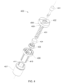
- FIG. 4 is an exploded perspective view of a pestle assembly according to one or more embodiments of the present disclosure.
- FIGS. 5 A- 5 J generally disclose a series of non-limiting embodiments of a pestle head according to the present disclosure.
- FIG. 6 is a flowchart illustrating an automation sequence and related structural components according to one or more embodiments of the present disclosure.
- FIGS. 7 A- 7 C generally disclose non-limiting embodiments of the mortar cup (or cup) according to the present disclosure.
- FIG. 8 A generally discloses an inset pestle, inset mortar cup (or cup), and inset Well C combination.
- FIG. 8 B generally discloses an alternative inset pestle, inset mortar cup (or cup), and inset Well C combination.
- FIG. 9 A is a top planar view of an inset Well C with a first embodiment of raised processing elements.
- FIG. 9 B is a top planar view of an inset Well C with a second embodiment of raised processing elements.
- FIG. 9 C is a side perspective view of an inset Well C.
- FIG. 10 A is a perspective view of a four-piece embodiment of packaging for a set of tools comprising two clamshell tool set pairings, and a bottom tray configured to receive the set of tools.
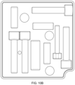
- FIG. 10 B is a top planar view of an upper clamshell piece for a first clamshell tool set pairing.
- FIG. 10 C is a bottom planar view of an upper clamshell piece for a first clamshell tool set pairing.
- FIG. 10 D is a top planar view of a lower clamshell piece for a first clamshell tool set pairing.
- FIG. 10 E is a bottom planar view of a lower clamshell piece for a first clamshell tool set pairing.
- FIG. 10 F is a top planar view of an upper clamshell piece for a second clamshell tool set pairing.
- FIG. 10 G is a bottom planar view of an upper clamshell piece for a second clamshell tool set pairing.
- FIG. 10 H is a top planar view of a lower clamshell piece for a second clamshell tool set pairing.
- FIG. 10 I is a bottom planar view of a lower clamshell piece for a second clamshell tool set pairing.
- FIG. 10 J is a top planar view of a lower clamshell piece for a first clamshell tool set pairing shown containing tools.
- FIG. 10 K is a top planar of a lower clamshell piece for a second clamshell tool set pairing shown containing tools.
- FIG. 11 is a top, front, and right side perspective view of a base unit.
- FIG. 12 is a front view of a base unit.
- FIG. 13 is a back view of a base unit.
- FIG. 14 is a left side view of a base unit.
- FIG. 15 is a right side view of a base unit.
- FIG. 16 is a top plan view of a base unit.
- FIG. 17 is a bottom plan view of a base unit.
- FIG. 18 is a top, front, and right side perspective view of a cartridge.
- FIG. 19 is a front view of a cartridge.
- FIG. 20 is a back view of a cartridge.
- FIG. 21 is a left side view of a cartridge.
- FIG. 22 is a right side view of a cartridge.
- FIG. 23 is a top plan view of a cartridge.
- FIG. 24 is a bottom plan view of a cartridge.
- tissue site may be a wound site, a burn site, a full-thickness skin defect, a vitiligo lesion, a site undergoing and/or suitable for re-pigmentation, a user or surgeon created wound, a trauma, and/or any suitable injury or defect.
- one or more systems for automated preparation of a regenerative epidermal suspension comprises a base unit, a cartridge, and a tissue disaggregator.
- a tissue disaggregator may be used to separate and/or disaggregate tissue.
- a tissue disaggregator may take many forms, such as a pestle, grinder, blade(s), various cutting and blunt instruments, cutting screens or any suitable tool. Although reference to a pestle is made throughout the specification, any suitable tissue disaggregator may be used.
- the system may further comprise a set of accompanying tools.
- the base unit may, in some embodiments, comprise a housing, a front cover, and a tissue processing area.
- the housing may comprise one or more side panels, a housing top surface, a display with one or more buttons, a touchscreen, or both one or more buttons and a touchscreen, a base frontplate, and two or more base footpads.
- the base unit may further comprise a pestle shaft (or shaft), a power supply, one or more circuit boards having one or more memory units, and one or more motors.
- the tissue processing area may comprise one or more heating elements, a docking spindle, one or more lighting elements, one or more side cartridge alignment protrusions, one or more rear cartridge alignment protrusions, and one or more control feedback sensors.
- the cartridge assembly may comprise a cartridge top cover, a raised processing area, one or more upper processing shelves, an “A”, “B”, “C”, and “D” opening in the cartridge top cover, one or more cartridge tabs, a mortar top cap, a mortar polymer ring, a mortar cup (or cup), a mortar screen (or screen), a well plate, an “A”, “B”, and “C” well within the well plate, one or more raised processing elements within the “C” well, a well heater cup disposed underneath the “A” well of the well plate, a drive sleeve, a cartridge bottom cover, a cartridge chip, a bottom cover opening in the cartridge bottom cover, and a docking spindle opening in the bottom cover opening in the cartridge bottom cover.
- the term “mortar cup” is interchangeable with the word “cup” and should not indicate that a pestle must be used with a cup.
- a suitable container or any suitable receiving receptacle may be used in place of the mortar cup or cup, herein this section and throughout the specification.
- the term “mortar screen” is interchangeable with the term “screen” and should not indicate that a pestle must be used with the screen.
- any suitable screen may be used in place of the mortar screen, herein this section and throughout the specification
- the pestle assembly may comprise a pestle top cap, a pestle spring, one or more pestle retention wires, a pestle spring cap, a pestle bottom cap, a pestle body, and a pestle head.
- the pestle may further comprise a pestle shaft (or shaft).
- the pestle head of the present disclosure may comprise at least one exterior side and a distal side, or “terminus” as used herein.
- the terminus is planar. In some embodiments, the terminus is dome-shaped.
- the terminus comprises an inset terminus, wherein a column having a smaller circumference than the exterior side extends distally from the terminus.
- the mortar cup (or cup) may comprise a sidewall, a distal opening, and a screen disposed across the distal opening.
- the mortar cup (or cup) distal opening and screen may be configured to be perpendicular to the sidewall, thereby corresponding to the planar terminus embodiment of the pestle head.
- the mortar cup (or cup) distal opening and screen may be curved, thereby corresponding to the dome-shaped terminus embodiment of the pestle head.
- the mortar cup (or cup) distal opening and screen may be configured to comprise an inset opening with a screen disposed across the inset opening, thereby corresponding to the inset terminus embodiment of the pestle head.
- the raised portion of one or more wells such as but not limited to Well C, may be generally planar, curved, or inset so as to align with the planar, dome-shaped, or inset pestle head and related planar, curved, or inset distal end and configuration of the mortar cup (or cup).
- the tools that accompany the cartridge and pestle may include, but are not limited to, one or more vials of buffer solution, one or more vials of enzyme solution, one or more vials of sterile water, one or more syringes, one or more needles, one more scalpels, one or more labels, and one or more spray nozzles.
- An automated method of preparing a regenerative epidermal suspension may, in some embodiments, comprise (i) starting position verification; (ii) user set up; and (iii) one or more tissue processing sequences.
- One or more methods disclosed herein may further comprise post-processing by a user.
- a system for automated preparation of a regenerative epidermal suspension may first verify the following starting positions: the mortar cup (or cup) is resting on the one or more upper processing shelves within the cartridge, the well plate is in the “A” position, and the pestle shaft (or shaft) is raised.
- User setup may comprise, in some embodiments, the steps of: (a) powering on the system, (b) inserting a predetermined quantity of buffer into Well B (buffer well) and Well C through openings “B” and “C” in the cartridge top cover respectively, (c) inserting a predetermined quantity of enzyme solution into Well A (enzyme well) through opening “A” in the cartridge top cover, (d) obtaining a tissue sample, (e) placing the tissue sample in the mortar cup (or cup) within the raised processing area of the cartridge top cover, (f) placing the pestle on top of the tissue sample in the mortar cup (or cup) within the raised processing area of the cartridge top cover, (g) lifting the front cover, (h) placing the cartridge into the tissue processing area such that the cartridge chip aligns with one or more control feedback sensors, and such that the heating element is aligned with the well heating cup, (i) closing the front cover, and (j) pressing one or more buttons on the display to initiate processing.
- One or more tissue processing sequences performed by the system may comprise, in embodiments, (a) the pestle shaft (or shaft) may lower and insert into the pestle cap through an opening in a top side of the pestle cap, (b) the pestle shaft (or shaft) may turn to engage the pestle body, (c) one or more raised elements disposed along an exterior side of the pestle body may engage with one or more recessed elements disposed along an interior side of the pestle head, (d) the pestle shaft (or shaft) may press, turn, or both press and turn the pestle body such that one or more raised lateral elements disposed on the exterior of the pestle head contacts an interior side of the mortar cup (or cup) and causes the mortar cup (or cup) to slip off the one or more upper processing shelves and lower into Well A (enzyme well), wherein when the mortar cup (or cup) is in Well A (enzyme well) the enzyme solution may pass through the mortar screen (or screen) and contact the tissue sample, (e) the heating element may warm the well heater cup, which in turn may
- the above-described sequence may alternatively comprise: (a) a retrieving element may lower from the upper housing portion and removably mate with the pestle shaft (or shaft), (b) the pestle shaft (or shaft) may turn to engage the pestle body, (c) one or more raised elements disposed along an exterior side of the pestle body may engage with one or more recessed elements disposed along an interior side of the pestle head, (d) the pestle shaft (or shaft) may press, turn, or both press and turn the pestle body such that one or more raised lateral elements disposed on the exterior of the pestle head contacts an interior side of the mortar cup (or cup) and causes the mortar cup (or cup) to slip off the one or more upper processing shelves and lower into Well A, wherein when the mortar cup (or cup) is in Well A the enzyme solution may pass through the mortar screen (or screen) and contact the tissue sample, (e) the heating element may warm the well heater cup, which in turn may
- Post-processing by a user may comprise the steps of (a) raising the front cover, (b) inserting one or more syringes into Well C through the “D” opening in the cartridge top cover, (c) drawing up the regenerative epidermal suspension into the syringe, and (d) treating one or more treatment areas on a patient with the regenerative epidermal suspension.
- the step of treating a patient with the regenerative epidermal suspension may comprise replacing the syringe's needle with a spray nozzle, then spraying the regenerative epidermal suspension on the treatment site.
- the system may raise the pestle shaft (or shaft) through the opening in the pestle top cap, and a user may remove the used cartridge and pestle.
- the pestle additionally comprises the pestle shaft (or shaft)
- the retrieving element may release the pestle shaft (or shaft), allowing the user to remove the used cartridge and pestle.
- a system for automated preparation of a regenerative epidermal suspension may comprise a non-transitory, tangible computer-readable medium having stored thereon computer-executable instructions, which, when executed by a computer processor, enable performance of a method may comprise (a) receiving, by a processor, an initiation signal, wherein the initiation signal indicates that a cartridge has been placed on a sensor, wherein the cartridge contains (i) a cartridge top surface comprising a raised processing area, at least two openings, a mortar cup (or cup) disposed within the raised processing area, a mortar screen (or screen) disposed within the mortar cup (or cup), a tissue sample disposed within the mortar cup (or cup), and a pestle having a pestle head at its terminus, wherein the pestle is disposed within the mortar cup (or cup) and wherein the pestle rests on the tissue sample; (ii) a well plate and at least three wells disposed along the well plate, wherein a first well contains a quantity of enzyme, a
- the initiation signal may be sent once the sensor detects the presence of the cartridge, and this may or may not start the sequence. However, in some examples, a user may start the sequence with a use start signal, such as by using a button, tap, switch, or any suitable mechanisms. In some examples, this signal may only be effective once the initiation signal from the sensor has been sent.
- the predetermined pound force sufficient to squeeze a solution off of the tissue sample may comprise 1-10 pounds of force, 2-5 pounds of force, 10-20 pounds of force, 20 pounds of force, or more than 20 pounds of force.
- One or more embodiments of the present disclosure may be implemented as a program product for use with a computer system.
- the program(s) of the program product defines functions of the embodiments (including the methods described herein) and can be contained on a variety of computer-readable storage media.
- Illustrative computer-readable storage media include, but are not limited to: (i) writable storage media (e.g., a hard disk, a portable drive such as a USB stick or a floppy disk) on which alterable information is stored, or (ii) non-writable storage media (e.g., read-only memory devices within a computer such as CD-ROM disks readable by a CD-ROM drive) on which information is permanently stored.
- writable storage media e.g., a hard disk, a portable drive such as a USB stick or a floppy disk
- non-writable storage media e.g., read-only memory devices within a computer such as CD-ROM disks readable
- Such computer-readable storage media when carrying computer-readable instructions that direct the functions of the present invention, are embodiments of the present invention.
- Other media include communications media through which information is conveyed to a computer, such as through a computer or telephone network, including wireless communications networks. The latter embodiment specifically includes transmitting information to/from the Internet and other networks.
- Such communications media when carrying computer-readable instructions that direct the functions of the present invention, are embodiments of the present invention.
- computer-readable storage media and communications media may be referred to herein as computer-readable media.
- the computer-readable storage media of the present invention may comprise one or more printed circuit board assemblies communicatively coupled to one or more memory units housed within the enclosure of the present invention.
- routines executed to implement the embodiments of the invention may be part of an operating system or a specific application, component, program, module, object, or sequence of instructions.
- the computer program of the present invention typically is comprised of a multitude of instructions that will be translated by the native computer into a machine-readable format and hence executable instructions.
- programs are comprised of variables and data structures that either reside locally to the program or are found in memory or on storage devices.
- various programs described hereinafter may be identified based upon the application for which they are implemented in a specific embodiment of the invention. However, it should be appreciated that any particular program nomenclature that follows is used merely for convenience, and thus the invention should not be limited to use solely in any specific application identified and/or implied by such nomenclature.
- Couple should be broadly understood and refer to connecting two or more elements or signals, electrically, mechanically or otherwise.
- Two or more electrical elements may be electrically coupled, but not mechanically or otherwise coupled; two or more mechanical elements may be mechanically coupled, but not electrically or otherwise coupled; two or more electrical elements may be mechanically coupled, but not electrically or otherwise coupled.
- Coupling (whether mechanical, electrical, or otherwise) may be for any length of time, e.g., permanent or semi-permanent or only for an instant.
- digital refers to any action, version, construct, representation, or other element that exists primarily or solely in a computer program or electronic medium.
- an effective amount of enzyme solution may comprise between 1 and 100 ml of enzyme solution and an effective amount of buffer solution may comprise 1 to 200 ml of buffer solution.
- an effective amount of time for a tissue sample to be in contact with the enzyme solution may comprise 5 to 30 minutes or in some embodiments 5 to 45 minutes or in some embodiments 5 to 60 minutes or longer.
- an effective amount of time to heat the enzyme solution may be 1 to 15 minutes, 1 to 30 minutes or longer than 30 minutes.
- the enzyme solution may comprise a pre-mixed solution comprising, at least, a quantity of enzyme in buffer solution, along with one or more additional elements.
- the enzyme in the enzyme solution may comprise but is not limited to one or more of trypsin, dispase, collagenase, trypsin-EDTA, thermolysin, pronase, hyaluronidase, elastase, papain and pancreatin.
- one or more enzymes such as trypsin, dispase, collagenase, trypsin-EDTA, thermolysin, pronase, hyaluronidase, elastase, papain and pancreatin may be traditionally sourced, such as for example via fermentation, or may be recombinant- or animal-derived.
- an enzyme solution may be formed by mixing lyophilized enzyme with an appropriate volume of fluid (e.g., water).
- the enzyme may comprise a recombinant trypsin, dispase, collagenase, trypsin-EDTA, thermolysin, pronase, hyaluronidase, elastase, papain or pancreatin enzyme, or more than one such recombinant enzyme.
- the enzyme solution is preferably free of calcium and magnesium.
- FIG. 1 generally discloses an embodiment of a system for automated preparation of a regenerative epidermal suspension 101 .
- Various elements of view in FIG. 1 will be elucidated in greater detail below.
- FIG. 2 illustrates an embodiment of a base unit according to an embodiment of the present disclosure
- FIG. 2 illustrates base unit 200 , housing 201 , tissue processing area 202 , housing base 203 , front cover 204 , heating element 205 , docking spindle 206 , display 207 , menu button 1 208 , menu button 2 209 , side cartridge alignment protrusions 210 , rear cartridge alignment protrusion 211 , base frontplate 212 , base pads 213 , housing top surface 214 , and control feedback sensor 215 .
- base unit 200 and its housing 201 may generally comprise a countertop-sized unit that widens from the housing top surface 214 towards its base and ultimately base pads 213 .
- the front end of housing 201 extending from display 207 to base front plate may be generally planar, as can be seen in FIG. 2 .
- two, three, four, five, or more base pads 213 are contemplated.
- Base unit 200 may further comprise one or more computer processing elements, such as but not limited to one or more printed circuit board assemblies, one or more hard drives, one or more circuit boards, one or more motherboards, one or more central processing units, one or more computer memory elements, one or more pieces of random access memory, and one or more processors (none shown).
- base unit 200 may comprise shapes such as a cylinder, a cube, a sphere, a pyramid, a cuboid, a hexagonal prism, or any other shape that would enable performance of the present disclosure.
- certain related elements may in such embodiments comprise different shapes as well.
- base unit 200 may be shaped as a cylinder, front cover 204 and display 207 may be curved to match. Similarly, it is contemplated that such related configuration or design changes may be made in order to practice the invention across different embodiments.
- base unit 200 may itself be comprised of different subassemblies that may be used in conjunction with each other to produce one or more regenerative epidermal suspensions.
- Heating element 205 is generally shown in FIG. 2 as a metal plate configured to conduct heat through well heater cup 318 , as is discussed more fully below. In some embodiments, however, other heating means are contemplated, such as but not limited to chemical heat elements such as a blister pack that heats when activated, radiation-heating elements, or other heating elements known in the art.
- front cover 204 may comprise a flat cover. In some embodiments, front cover 204 may comprise a rounded cover. In some embodiments, front cover 204 may be shaped approximately as three sides of a square. In some embodiments, front cover 204 may taper downwards, such that the upper portion of front cover 204 may be narrower than the bottom portion of front cover 204 . Conversely, in some embodiments, the upper portion of front cover 204 may be wider than the lower portion of front cover 204 . In some embodiments, front cover 204 may be translucent, clear, or otherwise “see-through.” In some embodiments, front cover 204 may be partially translucent and partially opaque. In some embodiments, front cover 204 may be opaque. In some embodiments, front cover 204 may be omitted.
- cartridge alignment protrusions 210 and rear cartridge alignment protrusion 211 may be configured, in some embodiments, to hold cartridge 300 in place during one or more processing sequences.
- cartridge alignment protrusions 210 and rear cartridge alignment protrusion 211 may in turn be placed either lower or higher, or one higher and the other lower, within tissue processing area 202 .
- tabs or protrusions may extend from front cover 204 to removably mate with cartridge alignment protrusions 210 .
- Docking spindle 206 may be configured to align with drive sleeve 319 . In some embodiments, however, docking spindle 206 may take any shape that may be advantageous to mate with drive sleeve 319 , or comparable element, that may be configured to rotate well plate 313 .
- docking spindle 206 may mate with drive sleeve 319 , or its comparable element, may reversibly mate via magnetic connection mating, Luer locking, snap-fit mating, bayonet-style mating, air hose style quick-connect mating, press-fit mating, “Mix2Vial” mating, and any other form of temporary, reversible, or in some embodiments permanent mating methods known in the relevant art.
- control feedback sensor 215 may comprise a temperature sensor, an electro-mechanical sensor, a pressure sensor, a vibration sensor, a light sensor, a sensor having two or more such properties, or two or more sensors working as a unit.
- sensor and “control feedback sensor” encompass both one sensor and two or more communicatively coupled sensors.
- Tissue processing sensor 215 may further comprise a chip, which in some embodiments may comprise a programmable chip.
- the one or more programmable chips in or connected to control feedback sensor 215 may be configured to receive and store information sufficient to indicate that a particular cartridge assembly 300 is a new cartridge assembly 300 or is a used cartridge assembly 300 .
- cartridge assembly 300 may further comprise one or more cartridge assembly programmable sensors (not shown).
- control feedback sensor 215 may be configured to cause the cartridge assembly sensor to read as new or used.
- control feedback sensor may be configured to communicate with the one or more computer elements via Bluetooth, near-field communication (NFC), inter-integrated circuit serial communication (I2C), serial peripheral interface (SPI), or any other such communications element.
- NFC near-field communication
- I2C inter-integrated circuit serial communication
- SPI serial peripheral interface
- FIG. 2 also shows the terminus of pestle shaft (or shaft) 401 .
- one or more motors may actuate pestle shaft (or shaft) 401 up and down, rotationally, laterally, or in more than one such motion, within tissue processing area 202 .
- pestle shaft (or shaft) 401 may extend further into tissue processing area 202 than is generally shown in FIG. 2 .
- FIG. 3 A the reader can observe an exploded perspective view of a cartridge assembly according to an embodiment of the present disclosure. More specifically, FIG. 3 A tends to show cartridge assembly 300 , cartridge top cover 301 , raised processing area 302 , upper processing shelf 303 , “A” opening 304 , “B” opening 305 , “C” opening 306 , “D” opening 307 , cartridge tab 308 , mortar top cap 309 , mortar polymer ring 310 , mortar cup (or cup) 311 , mortar screen (or screen) 312 , well plate 313 , Well A 314 , Well B 315 , Well C 316 , raised processing elements 317 , lower well portion 317 a , well heater cup 318 , drive sleeve 319 , cartridge bottom cover 320 , bottom cover opening 321 , docking spindle opening 322 , and connection tabs 325 .
- cartridge top cover 301 may be generally disc shaped. In other embodiments, cartridge top cover 301 may be square-shaped, spherical, cube shaped, oblong, star-shaped, triangular, or any other shape capable of carrying out the present system and/or method. Similarly, in some embodiments, any of “A” opening 304 , “B” opening 305 , “C” opening 306 , and/or “D” opening 307 may be larger or smaller than generally shown in FIG. 3 A .
- any of “A” opening 304 , “B” opening 305 , “C” opening 306 , and/or “D” opening 307 may be of a different shape than a circle, such as for example an oval, a square, a diamond, or a triangle.
- one or more of mortar top cap 309 , mortar polymer ring 310 , and/or mortar cup (or cup) 311 may comprise one or more wing-shaped tabs on its upper surface.
- such wing-shaped tabs may be configured to rest mortar cup (or cup) 311 in either a raised or lowered position within raised processing area 302 , such as for purposes of illustration and not limitation by either resting on one or more upper processing shelves 303 or lowering down with “A” opening 304 to a lower position within raised processing area 302 , such as but not limited to a position wherein mortar screen (or screen) 312 , mortar cup (or cup) 311 , and a tissue sample are positioned within Well A 314 , Well B 315 , or Well C 316 in the presence of either enzyme solution or buffer solution.
- mortar screen (or screen) 312 may comprise one or more of a membrane filter, a 100 micron filter, a 50 micron filter, a 25 micron filter, a 10 micron filter, a 5 micron filter, a 1 micron filter, a magnetic filter, a microbead filter, a magnetic microbead filter, antibody/antigen receptors used as a filter, one or more size exclusion column(s), one or more centrifuges, or filtration via ionic exchange/polarity column.
- a membrane filter a 100 micron filter, a 50 micron filter, a 25 micron filter, a 10 micron filter, a 5 micron filter, a 1 micron filter, a magnetic filter, a microbead filter, a magnetic microbead filter, antibody/antigen receptors used as a filter, one or more size exclusion column(s), one or more centrifuges, or filtration via ionic exchange/polarity column.
- well plate 313 may be configured to rotate Well A 314 , Well B 315 , or Well C 316 underneath “A” opening 304 and raised processing area 302 , such that one or more wells that were originally located under “A” opening 304 , “B” opening 305 , “C” opening 306 , or “D” opening 307 may be rotated to align under “A” opening 304 and raised processing area 302 . It is contemplated that such rotation may be achieved, in some embodiments, when mortar cup (or cup) 311 is in the upper position and resting on upper processing shelves 303 .
- one or more of Well A 314 , Well B 315 , or Well C 316 may be pre-filled with processing media.
- This processing media may include, but not limited to, sterile water, buffer, enzyme, or a combination thereof.
- one or more motors of the present system may drive the pestle shaft (or shaft) 401 such that it causes pestle head 407 to apply rotational and grinding forces against a tissue sample in the presence of either enzyme solution or buffer solution, or both, inside of mortar cup (or cup) 311 and against mortar screen (or screen) 312 while pestle 400 is within mortar cup (or cup) 311 and mortar screen (or screen) 312 , and wherein mortar cup (or cup) 311 and mortar screen (or screen) 312 are in contact with such fluid while in Well A 314 , Well B 315 , or Well C 316 .
- mortar screen (or screen) 312 may rest on raised processing elements 317 .
- raised processing elements 317 may provide additional friction surfaces that may in some embodiments enhance the mechanical disaggregation caused by the rotational and grinding forces of pestle cap 407 .
- one or more raised processing elements 317 may keep one or more pieces of the tissue sample in place while pestle head 407 grinds on said tissue sample piece, thereby achieving enhanced mechanical disaggregation of the tissue sample piece.
- raised processing elements 317 may comprise a separate plate that rests in one or more of Well A 314 , Well B 315 , or Well C 316 .
- the one or more raised processing elements 317 may be configured as one or more straight line raised ridges that radiate out from a central point.
- the one or more raised processing elements 317 may be configured as one or more spiral-shaped ridges.
- the one or more raised processing elements 317 may comprise a plurality of pips or dots. In such embodiments, such pips or dots may be randomized in their placement, placed in a grid formation, be placed in a spiral orientation, or in any geometrical pattern.
- Lower well portion 317 a may, in some embodiments, comprise the recessed portion of Well C 316 , which as may be seen in FIG. 3 A , may in some embodiments comprise one or more raised processing elements 317 on the surface of lower well portion 317 a .
- lower well portion 317 a may be generally curved, flat, conical, or inset.
- the shape of lower well portion 317 a may be configured to align with the terminal portion of pestle head 407 and the shape of mortar screen (or screen) 312 .
- mortar screen (or screen) 312 may be flat and lower well portion 317 a may be either flat or slightly curved.
- mortar screen (or screen) 312 may be curved and lower well portion 317 a may be curved.
- conical mortar screen (or screen) 707 may be provided and lower well portion 317 a may be conical, such as for example, alternative lower well portion 322 .
- inset mortar cup (or cup) 710 may be provided and lower well portion 317 a may be inset such as for example inset lower well portion 801 .
- the diameter of pestle head 407 may be configured to fit within the lower opening of mortar cup (or cup) 311 or the lower opening of inset mortar cup (or cup) 710 .
- the diameter of the lower opening of mortar cup (or cup) 311 may comprise 2 cm.
- the diameter of the lower opening of inset mortar cup (or cup) 710 may comprise 2 cm.
- the diameter of pestle head 407 may comprise 2 cm or slightly less than 2 cm.
- the diameter of lower well portion 317 a may comprise 2 cm or slightly larger than 2 cm.
- the diameter of inset lower well portion 801 may comprise 2 cm or slightly larger than 2 cm.
- the diameter of mortar screen (or screen) 312 may comprise 2 cm or slightly larger than 2 cm.
- the diameter of the lower opening of mortar cup (or cup) 311 may comprise 1 cm.
- the diameter of the lower opening of inset mortar cup (or cup) 710 may comprise 1 cm.
- the diameter of pestle head 407 may comprise 1 cm or slightly less than 1 cm.
- the diameter of lower well portion 317 a may comprise 1 cm or slightly larger than 1 cm.
- the diameter of inset lower well portion 801 may comprise 1 cm or slightly larger than 1 cm.
- the diameter of mortar screen (or screen) 312 may comprise 1 cm or slightly larger than 1 cm.
- the diameter of the lower opening of mortar cup (or cup) 311 may comprise 2 cm to 5 cm.
- the diameter of the lower opening of inset mortar cup (or cup) 710 may comprise 2 cm to 5 cm.
- the diameter of pestle head 407 may comprise 2 cm to 5 cm.
- the diameter of lower well portion 317 a may comprise 2 cm to 5 cm.
- the diameter of inset lower well portion 801 may comprise 2 cm to 5 cm.
- the diameter of mortar screen (or screen) 312 may comprise 2 cm to 5 cm.
- the diameter of the lower opening of mortar cup (or cup) 311 may be greater than 5 cm.
- the diameter of the lower opening of inset mortar cup (or cup) 710 may be greater than 5 cm.
- the diameter of pestle head 407 may be greater than 5 cm.
- the diameter of lower well portion 317 a may be greater than 5 cm.
- the diameter of inset lower well portion 801 may be greater than 5 cm.
- the diameter of mortar screen (or screen) 312 may be greater than 5 cm.
- the diameter of the lower opening of mortar cup (or cup) 311 may be less than 1 cm.
- the diameter of the lower opening of inset mortar cup (or cup) 710 may be less than 1 cm.
- the diameter of pestle head 407 may be less than 1 cm.
- the diameter of lower well portion 317 a may be less than 1 cm.
- the diameter of inset lower well portion 801 may be less than 1 cm.
- the diameter of mortar screen (or screen) 312 may be less than 1 cm.
- one or more of Well A 314 , Well B 315 , or Well C 316 may be shaped generally as cylinders and accordingly comprise at least one sidewall and at least one distal or bottom side. It is contemplated that in some embodiments, one or more of Well A 314 , Well B 315 , or Well C 316 may comprise shapes other than cylinders, such as spherical, cuboid, or any other geometric shape.
- the at least one raised processing element may be disposed along one or more of the at least one sidewall or distal bottom end of one or more of Well A 314 , Well B 315 , or Well C 316 .
- the diameter of Well C 316 may be narrower or wider, or its vertical length deeper or shallower, to allow for differences in buffer solution, which in turn may allow for differences in the present disclosure's regenerative epidermal solution's expansion ratio.
- the diameter of Well C 316 may be either narrower or shallower, or both narrower and shallower, to support processing either a smaller volume of buffer, such as 5 mls, or a larger volume of buffer, such as 500 mls, by a system for automated preparation of a regenerative epidermal suspension according to at least one embodiment of the present disclosure.
- cartridge bottom cover 320 , bottom cover opening 321 , and docking spindle opening 322 may be configured such that they are configured to wrap around heating element 205 , docking spindle 206 , and control feedback sensor 215 .
- cartridge bottom cover 320 may comprise a shape with no cutout, such that cartridge bottom cover 320 is configured to rest on top of one or more of heating element 205 , docking spindle 206 , and control feedback sensor 215 .
- one or more motors in housing 201 may drive docking spindle 206 such that docking spindle 206 turns against drive sleeve 319 , which then may rotate well plate 313 within cartridge top cover 301 .
- cartridge assembly 300 and its constituent parts such as but not limited to cartridge top cover 301 , raised processing area 302 , “A” opening 304 , “B” opening 305 , “C” opening 306 , “D” opening 307 , well plate 313 , Well A 314 , Well B 315 , Well C 316 , heater cup 318 , drive sleeve 319 , and cartridge bottom cover 320 may be configured in a linear format.
- cartridge top cover 301 may be generally rectangular in shape, with raised processing area 302 and its “A” opening 304 , “B” opening 305 , “C” opening 306 , and “D” opening 307 disposed in a line along the top edge of cartridge top cover 301 .
- well plate 313 may be generally rectangular also, with Well A 314 , Well B 315 , and Well C 316 disposed in a line.
- cartridge bottom cover 320 may also be configured in a rectangle shape.
- a linear arrangement of such elements as raised processing area 302 , “A” opening 304 , “B” opening 305 , “C” opening 306 , “D” opening 307 , Well A 314 , Well B 315 , Well C 316 , heater cup 318 , or drive sleeve 319 does not necessarily necessitate a rectangular configuration of elements such as but not limited to cartridge top cover 301 , well plate 313 , and cartridge bottom cover 320 .
- cartridge top cover 301 , well plate 313 , and cartridge bottom cover 320 may be configured in a different shape, such as an oval, a square, or a circle and still be configured to support a linear motion and processing sequence.
- “A” opening 304 , “B” opening 305 , “C” opening 306 , “D” opening 307 , Well A 314 , Well B 315 , or Well C 316 may be labeled with alternative identifying marks such as numbers, symbols, colors, color coding, or other sequential or nonsequential identifying marks.
- “A” opening 304 , “B” opening 305 , “C” opening 306 , and “D” opening 307 may be numbered 1, 2, 3, and 4, while Well A 314 , Well B 315 , and Well C 316 may retain their alphabetic designations.
- A” opening 304 , “B” opening 305 , “C” opening 306 , and “D” opening 307 may retain their alphabetic designations, while Well A 314 , Well B 315 , and Well C 316 may be numbered 1, 2, 3, and 4.
- the tissue sample may be harvested via corkscrew slicer such as a food processor, by electroporation, by biopsy, by punch biopsy, by dermatome, by DermaBlade, or by any other instrument or method known in the relevant art for skin sample acquisition and/or tissue sample acquisition.
- corkscrew slicer such as a food processor, by electroporation, by biopsy, by punch biopsy, by dermatome, by DermaBlade, or by any other instrument or method known in the relevant art for skin sample acquisition and/or tissue sample acquisition.
- deactivation of the enzyme may be accomplished in one or more of Well A 314 , Well B 315 , or Well C 316 by rinsing the tissue sample in buffer, one or more trypsin inhibitors, by vacuum removal, by semi-permeable membrane, by an enzyme-specific receptor in a column filtration process, by pressure differential, by magnetic microbeads, or by any other method known in the relevant art.
- fluid transfer within cartridge assembly 300 may be accomplished by syringe plunger/pulling action, by magnetic fluid transfer, by motorized fluid transfer for example a stepper, by vacuum pressure, by fluidic pressure, by gravity, by concentration gradient, or any other such mechanism known in the art.
- the regenerative epidermal suspension may be applied to a patient by direct spray on a treatment area via a spray nozzle, direct spray on a treatment area via an ultrasonic or piezoelectric atomizer, direct spray on a treatment area via a rotating spray nozzle having variable spray patterns, by dripping on a treatment area using a dripper or a syringe, by application to a dressing or media, by combining the regenerative epidermal suspension with a foam, by combining the regenerative epidermal suspension with an electrospun bandage, by combining the regenerative epidermal suspension with a wearable such as but not limited to a glove or socks, by combining the regenerative epidermal suspension with elements required to make a paste, by combining the regenerative epidermal suspension with elements required to make a salve, by combining the regenerative epidermal suspension with elements required to make a balm, by combining the regenerative epidermal suspension with elements required to make a “lipstick” style
- Well C 316 may in some embodiments comprise an oval-shaped upper well portion, one or more moon-shaped lower well shelfs, a lower well portion with in some embodiments raised processing elements 317 disposed along the lower well portion, and an inner well portion located at the center of the lower well portion.
- the lower well portion may comprise a shallow fluid receptacle.
- the lower well portion may generally comprise a circular shape.
- a viewer of FIG. 3 A may also perceive that the inner well portion may itself also be circular, and may as mentioned in some embodiments be disposed in the center of the lower well portion.
- lower well portion may slope towards the inner well portion at a variety of degrees.
- FIG. 3 A discloses a relatively flat slope, but as may be seen in FIG. 7 , other embodiments may provide for an inner well portion having steeper slopes.
- Inner well portion may in some embodiments be shaped as a shallow tray with a slight slope towards its center, as generally disclosed in FIG. 3 A , or may be more conical, as depicted in FIG. 7 .
- raised processing elements 317 may, in such alternative embodiments of lower well portion, comprise more or fewer elements than shown in FIG. 3 A , or may comprise a different orientation than shown.
- inner well portion may comprise a flat surface, may itself comprise a depression, or may in some embodiments comprise a raised element.
- FIG. 3 B shows additional detail on cartridge top cover 301 , raised processing area 302 , and upper processing shelf 303 , among other elements.
- raised processing area 302 may generally comprise one or more vertical elements 323 , each of which may further comprise a cutout 324 .
- raised processing area 302 may be configured that cutout 324 may be configured to allow passage of one or more mortar cup (or cup) tabs 701 through its interior, and upper processing shelf 303 may be configured such that a mortar cup (or cup) tab 701 may rest upon the surface of upper processing shelf, thereby creating space under mortar cup (or cup) 311 and the lower portions of raised processing area 302 .
- Such space may, in some embodiments, enable well plate 313 to rotate one or more of Well A 314 , Well B 315 , or Well C 316 underneath mortar cup (or cup) 311 .
- the present system may be configured such that by turning pestle 400 while pestle 400 is removably mated to mortar cup (or cup) 311 , mortar cup (or cup) tabs 701 may twist off of upper processing shelf 303 , pass through cutout 324 , and allow mortar cup (or cup) 311 to lower within vertical element 323 to a lower position, wherein at least a portion of mortar cup (or cup) 311 may be inside of Well A 314 , Well B 315 , or Well C 316 in a lower position within raised processing area 302 .
- FIG. 3 C generally discloses a bottom perspective view of cartridge top cover 301 .
- a viewer may perceive connection tab cutout 326 , each of which in some embodiments may be configured to receive a connection tab 325 and connection tab locking opening 327 .
- each connection tab 325 when assembled, may slide through connection tab cutout and the terminus of each connection tab 325 may extend through a connection tab locking opening 327 , thereby securing cartridge bottom cover 320 to cartridge top cover 301 .
- FIG. 3 D generally discloses a top perspective view of well plate 313 , along with Well A 314 , Well B 315 , and Well C 316 .
- a viewer may also perceive component opening 328 , raised processing area cutouts 329 , and tab stop 330 .
- FIG. 3 E generally discloses alternative well plate 331 , alternative lower well portion 332 , and alternative inner well portion 333 .
- the present invention may provide for a smaller Well A 314 , Well B 315 , or Well C 316 , as well as a more conical lower well portion, such as alternative lower well portion 332 .
- the circumference of alternative lower well portion 332 may be smaller than the circumference of the lower well portion shown in FIG. 3 A . Accordingly, and by way of non-limiting example, the steeper slope and smaller size of alternative lower well portion 332 may enable the effective processing and collection of smaller skin samples or smaller fluid volumes.
- FIG. 3 F generally discloses the underside of an embodiment of well plate 313 , along with the undersides of Well A 314 , Well B 315 , and Well C 316 as well as component opening 328 and raised processing area cutouts 329 .
- FIG. 3 G generally discloses a top perspective view of cartridge bottom cover 320 , connection tabs 323 , bottom cover opening 321 , and docking spindle opening 322 .
- cartridge bottom cover 320 comprises a plurality of raised elements radiating outward from cartridge bottom cover 320 as generally disclosed in FIG. 3 G , such a configuration is shown in FIG. 3 G for illustration purposes only and other embodiments are contemplated, such as a smooth surface for the top side of cartridge bottom cover 320 , a grid pattern for the top side of cartridge bottom cover 320 .
- a smooth surface for the top side of cartridge bottom cover 320 and the other related elements of cartridge 300 for example cartridge top cover 301 and well plate 313 may comprise an alternative shape, such as a square or a rectangle.
- FIG. 3 H generally discloses a bottom perspective view of cartridge bottom cover 320 , connection tabs 323 , bottom cover opening 321 , and docking spindle opening 322 .
- FIG. 4 the viewer may observe an exploded perspective view of a pestle 400 in accordance with an embodiment of the present disclosure. More specifically, FIG. 4 tends to disclose pestle 400 , pestle shaft (or shaft) 401 , pestle top cap 402 , pestle spring 403 , pestle spring cap 404 , pestle bottom cap 405 , pestle body 406 , pestle head 407 , pestle retention wire 1 408 , pestle retention wire 2 409 , pestle body ridge 410 , and pestle head interior notches 411 .
- pestle 400 may comprise pestle top cap 402 , pestle spring 403 , pestle spring cap 404 , pestle bottom cap 405 , pestle body 406 , pestle head 407 , pestle retention wire 1 408 , and pestle retention wire 2 409 .
- pestle shaft (or shaft) 401 may comprise an element of base unit 200
- pestle 400 may comprise the other elements shown in FIG. 4 .
- pestle 400 may comprise simply pestle top cap 402 , pestle body 406 , and pestle head 407 .
- pestle 400 may comprise simply pestle top cap 402 and pestle head 407 .
- pestle 400 may comprise an alternative pestle head 407 having a closed top and a notch in the closed top configured to receive pestle shaft (or shaft) 401 .
- pestle 400 may comprise pestle top cap 402 , pestle spring 403 , pestle spring cap 404 , pestle bottom cap 405 , pestle body 406 , and pestle head 407 , but not pestle retention wire 1 408 , and pestle retention wire 2 409 .
- pestle 400 may comprise pestle top cap 402 , pestle spring cap 404 , pestle bottom cap 405 , pestle body 406 , and pestle head 407 , but not pestle spring 403 , pestle retention wire 1 408 , and pestle retention wire 2 409 .
- pestle spring 403 may instead comprise a force sensor, a transducer element, a force transducer, a force measuring sensor, a load sensor, a load cell, a tension force sensor, a compression force sensor, a tensile force sensor, a load pin, a load bearing, a stress sensor, a customized sensor, a pressure sensor, or another comparable element.
- tissue disaggregation may be accomplished by means of ultrasonic disaggregation, piezoelectric disaggregation, rotary disaggregation via one or more blades, linear disaggregation via one or more blades, blender, punch-through disaggregation, punch-through disaggregation via a mesh or filter, multi-stage punch-through disaggregation, grating such as via a cheese grater-shaped blade surface, “slap chop” disaggregation, spiral grinding disaggregation such as but not limited to a pestle having raised spiral grooves configured to grind tissue against a mortar wall, string slicer disaggregation, shaver disaggregation, actuation disaggregation such as but not limited to actuation in the presence of microbeads, microbubble disaggregation or cavitation disaggregation, magnetic disaggregation, and electromagnetic disaggregation.
- pestle 400 may either be configured differently or substituted with a different assembly suitable for such alternate disaggregati
- pestle shaft (or shaft) 401 may mate with pestle top cap 402 in the lock-and-key style generally shown in FIG. 4 .
- Pestle shaft (or shaft) 401 may mate with pestle top cap 402 via magnetic connection mating, Luer locking, snap-fit mating, bayonet-style mating, air hose style quick-connect mating, press-fit mating, “Mix2Vial” mating, and any other form of temporary, reversible, or in some embodiments permanent mating methods known in the relevant art.
- pestle shaft (or shaft) 401 may generally comprise the key shape disclosed in FIG.
- pestle shaft (or shaft) 401 may comprise a component of housing 201 rather than an element of the pestle 400 .
- pestle shaft (or shaft) 401 when pestle shaft (or shaft) 401 inserts through pestle top cap 402 , pestle shaft (or shaft) 401 may compress pestle spring 403 against pestle spring cap 404 . In turn, such force may cause pestle spring cap 404 to make contact with pestle bottom cap 405 , which may then make contact with pestle body 406 , which in some embodiments may be in removable mated contact with pestle head 407 . In some embodiments, therefore, one or more motors housed within housing 201 may turn, agitate, actuate, or otherwise manipulate pestle 400 by turning, agitating, actuating, or otherwise manipulating pestle shaft (or shaft) 401 .
- one or more motors housed within housing 201 may turn pestle shaft (or shaft) 401 such that one or more raised protrusions on one or more sides of pestle shaft (or shaft) 401 may make contact with one or more elements on the underside of pestle top cap 402 .
- pestle top cap 402 may turn pestle body 406 , which may also then turn pestle head 407 .
- the one or more motors turns pestle shaft (or shaft) 401 within pestle 400 , it causes pestle head 407 to generate rotational forces, which when pestle head 407 is in contact with a tissue sample, applies rotational force to the tissue sample.
- the above-described sequence, wherein one or more motors within housing 201 may be configured to press pestle shaft (or shaft) 401 against pestle spring 403 , which then presses against pestle spring cap 404 , which then presses against pestle bottom cap 405 , which then makes contact with pestle body 406 , which may itself already be in mated contact with pestle head 407 .
- the foregoing sequence may thereby cause pestle head 407 to apply pressure to the tissue sample, which in some embodiments may be disposed along mortar screen (or screen) 312 .
- the pestle spring 403 force constant may be adjusted to apply a particular spring force in the pestle spring 403 axis through the pestle body 406 and pestle head 407 .
- Such pressure on the tissue sample may provide a grinding force on the tissue, and when such pressure is applied in combination with one or more turning motions by pestle head 407 against the tissue sample, it may apply both rotational and grinding forces against the tissue sample.
- the sequence described above, wherein one or more motors housed within housing 201 turn pestle head 401 such that pestle shaft (or shaft) 401 makes contact with one or more elements on the underside of pestle top cap 402 , and wherein such contact turns pestle top cap 402 , which turns pestle body 406 , which also then turns pestle head 407 , may be useful to raise or lower mortar cup (or cup) 311 within raised processing area 302 .
- a clockwise turning motion by pestle shaft (or shaft) 401 against pestle top cap 402 may cause mortar cup (or cup) 311 and pestle 400 to raise up onto upper processing area 303 such that one or more tabs on mortar top cap 309 , mortar polymer ring 310 , or mortar cup (or cup) 311 cause mortar cup (or cup) 311 and pestle 400 to rest on the upper processing area 303 , which in some embodiments may enable well plate 313 to rotate Well A 314 , Well B 315 , or Well C 316 underneath raised processing area 302 .
- a counterclockwise turning motion by pestle shaft (or shaft) 401 against pestle top cap 402 may cause mortar cup (or cup) 311 and pestle 400 to raise up onto upper processing area 303 such that one or more tabs on mortar top cap 309 , mortar polymer ring 310 , or mortar cup (or cup) 311 cause mortar cup (or cup) 311 and pestle 400 to rest on the upper processing area 303 , which in some embodiments may enable well plate 313 to rotate Well A 314 , Well B 315 , or Well C 316 underneath raised processing area 302 .
- a clockwise turning motion by pestle shaft (or shaft) 401 against pestle top cap 402 may cause mortar cup (or cup) 311 and pestle 400 to lower from upper processing area 303 into one or more of Well A 314 , Well B 315 , or Well C 316 , wherein one or more tissue processing steps may be carried out.
- a counterclockwise turning motion by pestle shaft (or shaft) 401 against pestle top cap 402 may cause mortar cup (or cup) 311 and pestle 400 to lower from upper processing area 303 into one or more of Well A 314 , Well B 315 , or Well C 316 , wherein one or more tissue processing steps may be carried out.
- the turning motion applied by pestle shaft (or shaft) 401 against pestle top cap 402 is counterclockwise.
- pestle 400 may comprise four pestle head interior notches 411 , which in some embodiments may correspond to four pestle body ridges 410 , disposed on pestle body 406 .
- pestle 400 may comprise three pestle head interior notches 411 , which in some embodiments may correspond to three pestle body ridges 410 .
- pestle 400 may comprise two pestle head interior notches 411 , which in some embodiments may correspond to two pestle body ridges 410 .
- pestle 400 may comprise one pestle head interior notch 411 , which in some embodiments may correspond to one pestle body ridge 410 .
- pestle 400 may comprise five or more pestle head interior notches 411 , which in some embodiments may correspond to five or more pestle body ridges 410 .
- FIGS. 5 A- 5 H illustrate a series of alternative embodiments of a pestle head 407 according to various embodiments of the present disclosure. More specifically, FIG. 5 A tends to show a pestle head 407 with a smooth exterior and raised bumps or “pips” on its terminus. FIG. 5 B tends to show a pestle head 407 with a smooth exterior and a raised spiral shape on its terminus.
- FIG. 5 C tends to show a pestle head 407 with a raised spiral pattern on its exterior and a raised spiral shape on its terminus.
- FIG. 5 D tends to show a pestle head 407 with a raised spiral pattern on its exterior and raised bumps or “pips” on its terminus.
- FIG. 5 E tends to show a pestle head 407 with a smooth exterior and a raised waffle pattern on its terminus.
- FIG. 5 F tends to show a pestle head 407 with an exterior comprised of repeating right angles and a raised radiating line pattern on its terminus.
- the pestle head 407 may be composed of one or more rubbers such as but not limited to silicone rubber, natural rubber, butadiene rubber, butyl rubber or IIR, ethylene propylene diene monomer or EPM or EPDM, fluoroelastomers or FKM/Viton, isoprene rubber, nitrile rubber or NBR, or styrene butadiene rubber; metals such as but not limited to stainless steel, copper, titanium, cobalt chrome, aluminum, magnesium, gold, platinum, silver, iridium, tantalum; any type of plastic such as but not limited to polycarbonate, polypropylene, acrylonitrile butadiene styrene or ABS, polyethylene, polymethyl methacrylate, polyvinyl chloride or PVC, polyethylene terephthalate glycol or PETG, polylactic Acid PLA, or any combination of such materials or other types of rubber, metal, or plastic known in the art.
- the pestle head 407 may be composed of one or more rubbers
- FIGS. 5 G and 5 H generally disclose raised lateral element 501 and raised element opening 502 as well as wide-tapered pestle head 503 , narrow-tapered pestle head 505 , wide pestle head point 504 , narrow pestle head point 506 , wide spiral raised groove pattern 505 , and narrow spiral raised groove pattern 509 . It should be noted that raised lateral element 501 and raised element opening 502 may also be seen in FIGS. 5 A- 5 E .
- wide-tapered pestle head 504 or narrow-tapered pestle head 505 may be paired with tapered mortar cup (or cup) 801 , which may be observed in FIG. 8 B .
- wide-tapered pestle head 504 or narrow-tapered pestle head 505 together with tapered mortar cup (or cup) 801 , may be configured for use with alternative lower well portion 702 as generally disclosed in FIG. 7 A .
- wide-tapered pestle head 504 or narrow-tapered pestle head 505 may in some embodiments comprise any of the raised elements disclosed in FIGS. 5 A- 5 F in addition to or in combination with wide spiral raised groove pattern 508 or narrow spiral raised groove pattern 509 .
- two raised lateral elements 501 may generally form a ring around pestle head 407 , separated by one or more raised element openings 502 .
- the ring shape may comprise a single-opening ring wherein a single raised lateral element 501 comprises a single raised element opening 502 disposed along it.
- a two-opening ring shape may comprise two raised lateral elements 501 separated by two raised element openings 502 .
- the ring shape may comprise three or more raised lateral elements 501 separated by three or more raised element openings 502 .
- two or more raised lateral elements 501 may be disposed along pestle head 407 in any order, such as but not limited to a staggered order. Accordingly, and by way of illustration, two ring-shaped arrangements comprising one or more raised lateral elements 501 separated by one or more raised element openings 502 may be disposed along pestle head 407 , one above the other. In some such embodiments, the raised element openings 502 may be aligned with one another relative to the long axis of pestle head 407 , or in some embodiments they may be staggered or in any order relative to each other and the long axis of pestle head 407 .
- raised lateral element 501 may be wider, narrower, taller, or shorter than shown in FIGS. 5 A- 5 E and FIGS. 5 G- 5 H .
- raised element openings 502 may not be tapered. In variations comprising two or more raised element openings 502 , some raised element openings 502 may be tapered while other raised element openings 502 are not tapered.
- the raised element openings may be aligned vertically along pestle cap 407 , may be staggered or otherwise not aligned relative to pestle cap 407 , or some raised element openings 502 may be aligned with each other and some raised element openings 502 may not be aligned with each other, relative to pestle cap 407 .
- two or more raised lateral elements 501 may have one or more openings.
- the raised ring element may taper to a point on either side of the one or more openings.
- the raised element may comprise a raised ring comprising two openings, wherein the raised ring element may taper to a point on either side of the one or more openings.
- the raised lateral element generally disclosed in FIGS. 5 A- 5 E and FIGS. 5 G- 5 H which in some embodiments may further comprise one or more openings, may be configured such that, when pestle head 407 is inserted into mortar cup (or cup) 311 past interior ridge 803 , friction between pestle head 407 and the interior of mortar cup (or cup) 311 may enable pestle 400 , via said friction, to raise mortar cup (or cup) 311 and to otherwise manipulate mortar cup (or cup) 311 , such as but not limited to lowering mortar cup (or cup) 311 at a controlled or intended rate, rotating mortar cup (or cup) 311 , or otherwise actuating or moving mortar cup (or cup) 311 .
- FIG. 5 I generally discloses an inset pestle head 517 having an inset terminus 509 with raised spiral elements 511 on the exterior of the inset terminus 509 .
- inset terminus 509 may comprise a cylinder having a smaller diameter than pestle head cylinder 508 .
- transition terminus 501 may comprise a sloped or curved edge between inset terminus 509 and pestle head cylinder 508 .
- FIG. 5 I also generally discloses a different angle on raised lateral element 501 .
- raised lateral element 501 may comprise a flat top edge 514 and tapered lower edge 515 .
- raised lateral element 501 may be configured to enable pestle head 407 to enter the interior of mortar cup (or cup) 311 but to be prevented from exiting the interior of mortar cup (or cup) 311 .
- tapered lower edge 515 may enable pestle head 407 to push past mortar top cap 309 , mortar polymer ring 310 , or both mortar top cap 309 and mortar polymer ring 310 , to enter the interior of mortar cup (or cup) 311 , but flat top edge 514 may prevent pestle head 407 from exiting the interior of mortar cup (or cup) 311 because flat top edge 514 may catch on mortar top cap 309 , mortar polymer ring 310 , or both mortar top cap 309 and mortar polymer ring 310 .
- raised lateral element 501 and its flat top edge 514 and/or tapered lower edge 515 may perform the same function for wide-tapered pestle cap head 503 , narrow-tapered pestle cap head 505 , inset pestle head 517 , a conical pestle head, and any other pestle head described or contemplated in the present disclosure.
- FIG. 5 I also generally discloses raised spiral elements 511 and spiral interstices 512 , along with inset terminus distal edge 513 .
- inset pestle head 517 is rotated within a corresponding inset mortar cup (or cup) 710 , such as may be seen in FIG. 8 A , FIG.
- raised spiral elements 511 may grind tissue against an interior sidewall of inset mortar cup (or cup) 710 .
- tissue in solution may collect in one or more spiral interstices 512 or may be circulated within inset mortar cup (or cup) 710 .
- FIG. 5 J generally discloses an embodiment of inset pestle head 517 having an inset terminus 509 and a plurality of pips 516 disposed along the distal end of having an inset terminus 509 .
- the exterior of inset terminus 509 in some embodiments may be generally smooth as shown in FIG. 5 J
- the exterior of inset terminus 509 may comprise raised spiral elements 511 and corresponding spiral interstices 512 , additional pips, vertical raised elements, horizontal raised elements, diagonal raised elements, recessed portions, outward-extending elements, and other such elements.
- FIG. 6 comprises a flowchart tending to show a processing sequence of a system for automated preparation of a regenerative epidermal suspension according to at least one embodiment of the present disclosure.
- one or more elements of the processing sequence disclosed in FIG. 6 may be omitted or performed in a different sequence.
- the system may first cause the pestle to engage the mortar cup (or cup) 601 . Then, the system may cause the pestle to move the mortar cup (or cup) off the upper processing shelf and into Well A 602 . Next, the heating element may warm the enzyme solution in Well A 603 . Next, the system may cause the pestle shaft (or shaft) to actuate the pestle such that the pestle causes the tissue sample to come into contact with the enzyme solution 604 . Next, the system may cause the pestle to raise the mortar cup (or cup) into an “up” position 605 .
- the system may cause the pestle to press down on the tissue sample three times to squeeze the enzyme solution off tissue sample 606 .
- the system may rotate the well plate such that Well B moves to a position underneath the mortar cup (or cup) 607 .
- the system may cause the pestle to move the mortar cup (or cup) off the upper processing shelf and into Well B 608 .
- the system may cause the pestle shaft (or shaft) to actuate the pestle such that the pestle causes the tissue sample to come into contact with a first quantity of buffer solution 609 .
- the system may cause the pestle to raise the mortar cup (or cup) into the “up” position 610 .
- the system may cause the pestle to press down on the tissue sample three times to squeeze the buffer solution off the tissue sample 611 .
- the system may rotate the well plate such that Well C is moved to a position underneath the mortar cup (or cup) 612 .
- the system may cause the pestle to move the mortar cup (or cup) off the upper processing shelf and into Well C 613 .
- the system may cause the pestle shaft (or shaft) to actuate the pestle so as to apply rotational and grinding forces on the tissue sample in presence of a second quantity of buffer solution, a mortar screen (or screen), and raised processing elements 614 .
- the system may cause the pestle to raise the mortar cup (or cup) into the “up” position 615 .
- the system may cause the pestle to press down on the tissue sample three times to squeeze the buffer solution off the tissue sample 616 .
- the system may rotate the well plate such that Well C is moved underneath the D opening in the cartridge top cover 617 .
- the sensor may send a signal to the memory unit to record the just-completed processing event 618 .
- the system may alternatively cause the pestle shaft (or shaft) to actuate the pestle so as to apply linear force in addition to or in place of rotational and grinding forces on the tissue sample in presence of a second quantity of buffer solution, a mortar screen (or screen), and raised processing elements 614 .
- the system may cause the pestle to apply linear, rotational, or grinding force, or a combination thereof, to the tissue sample without the presence of the mortar screen (or screen).
- the system may cause the pestle to apply linear, rotational, or grinding force, or a combination thereof, to the tissue sample without the presence of the raised processing elements.
- the nomenclature for the wells and openings recited in the processing sequence disclosed in FIG. 6 may comprise one or more numbers, one or more symbols, one or more raised features, or a combination thereof.
- FIG. 7 A and FIG. 7 B generally disclose embodiments of a mortar cup (or cup) according to embodiments of the present disclosure. More specifically, with respect to FIG. 7 A , attention is drawn to tab 701 , tab post 702 , interior ridge 703 , upper mortar portion 704 , lower mortar portion 705 , and inter-tab notch 706 . With respect to FIG. 7 B , attention is drawn to conical mortar screen (or screen) 707 , tapered mortar cup (or cup) design 708 , and mortar cup (or cup) ring 709 .
- upper mortar portion 704 may comprise a wider diameter than lower mortar portion 705 , with interior ridge 703 comprising a transition surface between upper mortar portion 704 and lower mortar portion 705 .
- pestle 400 may insert into mortar cup (or cup) 311 such that raised lateral elements 501 on pestle head 407 pass through upper mortar portion 704 , press across interior ridge 703 , and removably mate with lower mortar portion 705 via friction.
- the pressure and friction from raised lateral elements 501 against the surface of lower mortar portion 705 may enable the pestle to lift mortar cup (or cup) 311 during one or more processing events or steps disclosed herein.
- raised lateral elements 501 may pass through upper mortar portion 704 , press across interior ridge 703 , and press against lower mortar portion 705 , but may be prevented from exiting mortar cup (or cup) 311 by mortar top cap 309 , mortar polymer ring 310 , or both mortar top cap 309 and mortar polymer ring 310 .
- FIG. 7 C shows a side planar view of inset mortar cup (or cup) 710 .
- FIG. 8 A generally discloses an embodiment of a pestle, mortar cup (or cup), and Well C combination comprising pestle 400 with inset pestle head 517 inset mortar cup (or cup) 710 and inset Well C 802 having inset lower well portion 801 .
- FIG. 8 B generally discloses an alternative embodiment of a pestle, mortar cup (or cup), and Well C combination comprising pestle 400 with inset pestle head 517 inset mortar cup (or cup) 710 and inset Well C 802 having inset lower well portion 801 .
- FIG. 9 A shows a top planar view of inset Well C 802 having inset lower well portion 801 , along with tall raised processing elements 901 .
- FIG. 9 B shows a top planar view of inset Well C 802 having inset lower well portion 801 , along with short raised processing elements 902 .
- FIG. 9 C shows a side perspective view of inset Well C 802 and side protrusions 903 .
- FIG. 10 A generally discloses a perspective view of a four-piece embodiment of packaging for a set of tools comprising two clamshell tool set pairings, and a bottom tray configured to receive the set of tools.
- the present disclosure may provide for two clamshell pairings, each of which may contain one-half of a negative shape of a tool configured as a recess to receive said tool, wherein the tool is intended for use as part of a system for automated preparation of a cell suspension or as an accompaniment to a system for automated preparation of a cell suspension, and each piece may comprise the mirror image of the other.
- each clamshell pairing may be configured to removably contain one or more tools. As may be seen in FIG.
- the present disclosure may comprise two clamshell pairings.
- a system for automated preparation of a cell suspension may comprise one clamshell pairing containing tools, two clamshell pairings containing tools, three clamshell pairings containing tools, or four or more clamshell pairings containing tools.
- the one or more tools configured for use with a system for automated preparation of a cell suspension may be contained in a tray having a shape other than the clamshell pairing configuration shown in FIG. 10 A .
- the tools may in some embodiments be contained within a single tray, two trays, or three or more trays, wherein the one or more trays comprise one or more recesses configured to receive one side of each tool and a protective removable covering disposed along the surface of the tray.
- the bottom tray is shown as an open-topped pan with an in-cut design at one corner and an upper lip disposed along the entirety of the opening.
- the bottom tray may comprise a box, a bag, a sphere, or any other shape of object able to contain tools.
- the tray element and one or more clamshell pairing pieces may not comprise the in-cut corner element, or may comprise two or more in-cut corner elements.
- FIG. 10 B is a top planar view of an upper clamshell piece for a first clamshell tool set pairing.
- the recesses of the clamshell piece shown in FIG. 10 B may be configured to receive one or more scalpels, one or more syringes, one or more needles, and one or more vials.
- the recesses of the clamshell piece shown in FIG. 10 B may be configured to contain two or more sizes of tools, such as small, medium or large scalpels; small, medium or large syringes; small, medium or large needles; and small, medium or large vials.
- the vials may contain an enzyme solution or a buffer solution.
- Other embodiments may comprise more or fewer recesses configured to receive a tool, or may comprise recesses configured to receive different tools than the ones shown in FIG. 10 B .
- FIG. 10 C is a bottom planar view of an upper clamshell piece for a first clamshell tool set pairing.
- the recesses of the clamshell piece shown in FIG. 10 C may be configured to receive one or more scalpels, one or more syringes, one or more needles, and one or more vials.
- the recesses of the clamshell piece shown in FIG. 10 C may be configured to contain two or more sizes of tools, such as small, medium or large scalpels; small, medium or large syringes; small, medium or large needles; and small, medium or large vials.
- the vials may contain an enzyme solution or a buffer solution.
- Other embodiments may comprise more or fewer recesses configured to receive a tool, or may comprise recesses configured to receive different tools than the ones shown in FIG. 10 C .
- FIG. 10 D is a top planar view of a lower clamshell piece for a first clamshell tool set pairing.
- the recesses of the clamshell piece shown in FIG. 10 D may be configured to receive one or more scalpels, one or more syringes, one or more needles, and one or more vials.
- the recesses of the clamshell piece shown in FIG. 10 D may be configured to contain two or more sizes of tools, such as small, medium or large scalpels; small, medium or large syringes; small, medium or large needles; and small, medium or large vials.
- the vials may contain an enzyme solution or a buffer solution.
- Other embodiments may comprise more or fewer recesses configured to receive a tool, or may comprise recesses configured to receive different tools than the ones shown in FIG. 10 D .
- FIG. 10 E is a bottom planar view of a lower clamshell piece for a first clamshell tool set pairing.
- the recesses of the clamshell piece shown in FIG. 10 E may be configured to receive one or more scalpels, one or more syringes, one or more needles, and one or more vials.
- the recesses of the clamshell piece shown in FIG. 10 E may be configured to contain two or more sizes of tools, such as small, medium or large scalpels; small, medium or large syringes; small, medium or large needles; and small, medium or large vials.
- the vials may contain an enzyme solution or a buffer solution.
- Other embodiments may comprise more or fewer recesses configured to receive a tool, or may comprise recesses configured to receive different tools than the ones shown in FIG. 10 E .
- FIG. 10 F is a top planar view of an upper clamshell piece for a second clamshell tool set pairing.
- the recesses of the clamshell piece shown in FIG. 10 F may be configured to receive one or more nozzles, one or more syringes, and one or more needles.
- the recesses of the clamshell piece shown in FIG. 10 F may be configured to contain two or more sizes of tools, such as small, medium or large nozzles; small, medium or large syringes; and small, medium or large needle.
- the vials may contain an enzyme solution or a buffer solution.
- Other embodiments may comprise more or fewer recesses configured to receive a tool, or may comprise recesses configured to receive different tools than the ones shown in FIG. 10 F .
- FIG. 10 G is a bottom planar view of an upper clamshell piece for a second clamshell tool set pairing.
- the recesses of the clamshell piece shown in FIG. 10 G may be configured to receive one or more nozzles, one or more syringes, and one or more needles.
- the recesses of the clamshell piece shown in FIG. 10 G may be configured to contain two or more sizes of tools, such as small, medium or large nozzles; small, medium or large syringes; and small, medium or large needle.
- the vials may contain an enzyme solution or a buffer solution.
- Other embodiments may comprise more or fewer recesses configured to receive a tool, or may comprise recesses configured to receive different tools than the ones shown in FIG. 10 G .
- FIG. 10 H is a top planar view of a lower clamshell piece for a second clamshell tool set pairing.
- the recesses of the clamshell piece shown in FIG. 10 H may be configured to receive one or more nozzles, one or more syringes, and one or more needles.
- the recesses of the clamshell piece shown in FIG. 10 H may be configured to contain two or more sizes of tools, such as small, medium or large nozzles; small, medium or large syringes; and small, medium or large needle.
- the vials may contain an enzyme solution or a buffer solution.
- Other embodiments may comprise more or fewer recesses configured to receive a tool, or may comprise recesses configured to receive different tools than the ones shown in FIG. 10 H .
- FIG. 10 I is a bottom planar view of a lower clamshell piece for a second clamshell tool set pairing.
- the recesses of the clamshell piece shown in FIG. 10 I may be configured to receive one or more nozzles, one or more syringes, and one or more needles.
- the recesses of the clamshell piece shown in FIG. 10 I may be configured to contain two or more sizes of tools, such as small, medium or large nozzles; small, medium or large syringes; and small, medium or large needle.
- the vials may contain an enzyme solution or a buffer solution.
- Other embodiments may comprise more or fewer recesses configured to receive a tool, or may comprise recesses configured to receive different tools than the ones shown in FIG. 10 I .
- FIG. 10 J is a top planar view of a lower clamshell piece for a first clamshell tool set pairing shown containing tools.
- a viewer may perceive tools such as one or more scalpels, one or more syringes, one or more needles, and one or more vials.
- FIG. 10 K is a top planar view of a lower clamshell piece for a second clamshell tool set pairing shown containing tools.
- a viewer may perceive tools such as one or more nozzles, one or more syringes, and one or more needles.
- FIG. 11 is a top, front, and right side perspective view of a base unit.
- FIG. 11 illustrates a base unit, a housing, a tissue processing area, a housing base, a front cover, a heating element, a docking spindle, a display, two menu buttons, side cartridge alignment protrusions, a rear cartridge alignment protrusion, a base frontplate, a housing top surface, and a control feedback sensor.
- FIG. 12 is a front view of the base unit of FIG. 11 .
- FIG. 13 is a back view of the base unit of FIG. 11 .
- FIG. 14 is a left side view of the base unit of FIG. 11 .
- FIG. 15 is a right side view the base unit of FIG. 11 .
- FIG. 16 is a top plan view of the base unit of FIG. 11 .
- FIG. 17 is a bottom plan view of the base unit of FIG. 11 .
- FIG. 18 is a top, front, and right side perspective view of a cartridge.
- FIG. 11 is a top, front, and right side perspective view of a cartridge.
- FIG. 1 illustrates a cartridge assembly, a cartridge top cover, a raised processing area, an upper processing shelf, four distinct openings, and two cartridge tabs.
- FIG. 19 is a front view of the cartridge of FIG. 18 .
- FIG. 20 is a back view of the cartridge of FIG. 18 .
- FIG. 21 is a left side view of the cartridge of FIG. 18 .
- FIG. 22 is a right side view of the cartridge of FIG. 18 .
- FIG. 23 is a top plan view of the cartridge of FIG. 18 .
- FIG. 24 is a bottom plan view of the cartridge of FIG. 18 .
- the purpose of this study was to evaluate the performance of the present system for automated preparation of a regenerative epidermal suspension by assessing device output metrics relevant to biological function.
- the RECELL Device is a manual system for preparation of a regenerative epidermal suspension (“Manual Device”) that enables a clinician at point-of-care to prepare a regenerative epidermal suspension using a small piece of donor skin.
- the Manual Device is a single-use, stand-alone, battery-operated device that enables a thin skin sample (0.006-0.008′′) to be processed by a healthcare professional at point-of-care to prepare regenerative epidermal suspension for immediate delivery onto a prepared wound bed.
- Regenerative epidermal suspension contains a mixed population of single and generally viable cells, including keratinocytes, fibroblasts, and melanocytes, that are obtained from enzymatic and mechanical processing of the split-thickness skin sample.
- the cell suspension is applied to a prepared wound bed for the treatment of acute thermal burn wounds and full-thickness skin defects.
- the present disclosure and its Automated Device was designed and manufactured to overcome the challenges and shortcomings of previously known methods and devices, and to simplify preparation of regenerative epidermal suspension.
- Trained operators prepared regenerative epidermal suspension using a Manual Device and the Automated Device. For each processing sequence, the trained operators obtained two skin samples of identical size from adjacent locations on the same piece of donor skin. Then, simultaneously, operators used the Manual Device and the Automated Device to produce regenerative epidermal suspension from the identically-sized and same-donor skin samples. The operators repeated this process a total of six times: three times wherein each device was used to produce regenerative epidermal suspension from a 4 cm 2 skin sample, and three times wherein each device was used to produce regenerative epidermal suspension from a 24 cm 2 skin sample. Then, the parameters of the regenerative epidermal suspension obtained from each device were obtained and analyzed.
- the analyses indicate successful disaggregation of skin and isolation of cells for the lower and upper limit of skin sample sizes for both devices. Additionally, similar functional outputs were isolated for the Automated Device compared to the Manual Device. Collectively, the analyses indicate that both devices disaggregate the lower and upper limit of skin sample sizes with comparable results.
- tissue treatment and regenerative epidermal suspension relate to tissue treatment and regenerative epidermal suspension
- devices, systems and methods disclosed herein are not limited to these applications.
- Systems and methods disclosed herein are generally applicable to medical devices in general.
- any value of a threshold, limit, duration, etc. provided herein is not intended to be absolute and, thereby, can be approximate.
- any threshold, limit, duration, etc. provided herein can be fixed or varied either automatically or by a user.
- relative terminology such as exceeds, greater than, less than, etc. in relation to a reference value is intended to also encompass being equal to the reference value. For example, exceeding a reference value that is positive can encompass being equal to or greater than the reference value.
- relative terminology such as exceeds, greater than, less than, etc. in relation to a reference value is intended to also encompass an inverse of the disclosed relationship, such as below, less than, greater than, etc. in relations to the reference value.
- blocks of the various processes may be described in terms of determining whether a value meets or does not meet a particular threshold, the blocks can be similarly understood, for example, in terms of a value (i) being below or above a threshold or (ii) satisfying or not satisfying a threshold.
- the various components illustrated in the figures may be implemented as software or firmware on a processor, controller, ASIC, FPGA, or dedicated hardware.
- Hardware components such as controllers, processors, ASICs, FPGAs, and the like, can include logic circuitry.
- the features and attributes of the specific embodiments disclosed above may be combined in different ways to form additional embodiments, all of which fall within the scope of the present disclosure.
- the term “or” is used in its inclusive sense (and not in its exclusive sense) so that when used, for example, to connect a list of elements, the term “or” means one, some, or all of the elements in the list.
- the term “each,” as used herein, in addition to having its ordinary meaning, can mean any subset of a set of elements to which the term “each” is applied.
Landscapes
- Health & Medical Sciences (AREA)
- Life Sciences & Earth Sciences (AREA)
- Chemical & Material Sciences (AREA)
- Engineering & Computer Science (AREA)
- Bioinformatics & Cheminformatics (AREA)
- Organic Chemistry (AREA)
- Zoology (AREA)
- Wood Science & Technology (AREA)
- Biomedical Technology (AREA)
- General Health & Medical Sciences (AREA)
- Biochemistry (AREA)
- Genetics & Genomics (AREA)
- Sustainable Development (AREA)
- General Engineering & Computer Science (AREA)
- Microbiology (AREA)
- Biotechnology (AREA)
- Analytical Chemistry (AREA)
- Clinical Laboratory Science (AREA)
- Molecular Biology (AREA)
- Physics & Mathematics (AREA)
- Immunology (AREA)
- Virology (AREA)
- Cell Biology (AREA)
- Pathology (AREA)
- General Physics & Mathematics (AREA)
- Chemical Kinetics & Catalysis (AREA)
- Hematology (AREA)
- Thermal Sciences (AREA)
- Computer Hardware Design (AREA)
- Mechanical Engineering (AREA)
- Apparatus Associated With Microorganisms And Enzymes (AREA)
- Agricultural Chemicals And Associated Chemicals (AREA)
- Prostheses (AREA)
- Media Introduction/Drainage Providing Device (AREA)
- Filtration Of Liquid (AREA)
- Devices For Medical Bathing And Washing (AREA)
- Heart & Thoracic Surgery (AREA)
- Medical Informatics (AREA)
- Surgery (AREA)
- Animal Behavior & Ethology (AREA)
Abstract
Description
Claims (20)
Priority Applications (1)
| Application Number | Priority Date | Filing Date | Title |
|---|---|---|---|
| US18/395,415 US12180456B2 (en) | 2022-12-27 | 2023-12-22 | Tissue healing |
Applications Claiming Priority (3)
| Application Number | Priority Date | Filing Date | Title |
|---|---|---|---|
| US202263435446P | 2022-12-27 | 2022-12-27 | |
| US202363533586P | 2023-08-18 | 2023-08-18 | |
| US18/395,415 US12180456B2 (en) | 2022-12-27 | 2023-12-22 | Tissue healing |
Publications (2)
| Publication Number | Publication Date |
|---|---|
| US20240209296A1 US20240209296A1 (en) | 2024-06-27 |
| US12180456B2 true US12180456B2 (en) | 2024-12-31 |
Family
ID=89834434
Family Applications (5)
| Application Number | Title | Priority Date | Filing Date |
|---|---|---|---|
| US18/395,415 Active US12180456B2 (en) | 2022-12-27 | 2023-12-22 | Tissue healing |
| US18/395,405 Active US12270019B2 (en) | 2022-12-27 | 2023-12-22 | Automated method |
| US18/395,395 Abandoned US20240209299A1 (en) | 2022-12-27 | 2023-12-22 | Cartridge for tissue treatment |
| US18/395,288 Active US12281298B2 (en) | 2022-12-27 | 2023-12-22 | System for automated preparation of a regenerative epidermal suspension and related methods of use |
| US19/019,132 Pending US20250346849A1 (en) | 2022-12-27 | 2025-01-13 | Automated method |
Family Applications After (4)
| Application Number | Title | Priority Date | Filing Date |
|---|---|---|---|
| US18/395,405 Active US12270019B2 (en) | 2022-12-27 | 2023-12-22 | Automated method |
| US18/395,395 Abandoned US20240209299A1 (en) | 2022-12-27 | 2023-12-22 | Cartridge for tissue treatment |
| US18/395,288 Active US12281298B2 (en) | 2022-12-27 | 2023-12-22 | System for automated preparation of a regenerative epidermal suspension and related methods of use |
| US19/019,132 Pending US20250346849A1 (en) | 2022-12-27 | 2025-01-13 | Automated method |
Country Status (7)
| Country | Link |
|---|---|
| US (5) | US12180456B2 (en) |
| EP (2) | EP4644527A1 (en) |
| JP (1) | JP2026500565A (en) |
| CN (1) | CN120603927A (en) |
| AU (3) | AU2023415952A1 (en) |
| DE (3) | DE202023002795U1 (en) |
| WO (1) | WO2024145258A1 (en) |
Cited By (2)
| Publication number | Priority date | Publication date | Assignee | Title |
|---|---|---|---|---|
| US12270019B2 (en) | 2022-12-27 | 2025-04-08 | AVITA Medical Americas, LLC | Automated method |
| USD1112812S1 (en) | 2023-12-22 | 2026-02-10 | AVITA Medical Americas, LLC | Tissue processing cartridge |
Citations (262)
| Publication number | Priority date | Publication date | Assignee | Title |
|---|---|---|---|---|
| US1356794A (en) | 1919-12-27 | 1920-10-26 | Smith John Thomas | Skid-oiler |
| US2343079A (en) | 1941-12-22 | 1944-02-29 | Gen Motors Corp | Coupling |
| GB1238401A (en) | 1968-04-11 | 1971-07-07 | ||
| US3608553A (en) | 1969-09-04 | 1971-09-28 | Ultrasonic Systems | Ultrasonic method and apparatus for tissue grafting |
| US3860706A (en) | 1972-05-24 | 1975-01-14 | Dauch Seiyaku Company Limited | Method for curing stock symptoms |
| US4059486A (en) | 1976-11-03 | 1977-11-22 | Monsanto Company | Cell culture process |
| US4254226A (en) | 1979-09-13 | 1981-03-03 | Sloan Kettering Institute For Cancer Research | Process for growing human epidermal cells in tissue culture |
| US4304866A (en) | 1979-11-14 | 1981-12-08 | Massachusetts Institute Of Technology | Transplantable sheets of living keratinous tissue |
| US4350768A (en) | 1980-09-19 | 1982-09-21 | Bristol Myers Company | Method for preparing single cell suspension |
| US4377010A (en) | 1978-11-08 | 1983-03-22 | The Secretary Of State For Defence In Her Britannic Majesty's Government Of The United Kingdom Of Great Britain And Northern Ireland | Biocompatible material comprising a base polymer bulk graft polymerized with an ethylenically unsaturated carboxylic acid |
| GB2106552A (en) | 1981-09-02 | 1983-04-13 | Textima Veb K | Sliver forming guide |
| WO1983001384A1 (en) | 1981-10-26 | 1983-04-28 | Massachusetts Inst Technology | Cell-seeding procedures involving fibrous lattices |
| US4418691A (en) | 1981-10-26 | 1983-12-06 | Massachusetts Institute Of Technology | Method of promoting the regeneration of tissue at a wound |
| US4505266A (en) | 1981-10-26 | 1985-03-19 | Massachusetts Institute Of Technology | Method of using a fibrous lattice |
| US4510144A (en) | 1981-08-26 | 1985-04-09 | Newport Pharmaceuticals International | Methods of imparting immunomodulating activity with dihydrothiazolo purine derivatives |
| US4533635A (en) | 1979-07-13 | 1985-08-06 | Institut National De La Sante Et De La Recherche Medicale | Process for stimulating the growth of epidermal cells |
| US4595102A (en) | 1984-12-18 | 1986-06-17 | The Kendall Company | Kit for performing a medical procedure |
| US4649115A (en) | 1983-03-31 | 1987-03-10 | Sloan-Kettering Institute | Monoclonal antibodies to skin cells |
| US4736850A (en) | 1986-10-17 | 1988-04-12 | W. L. Gore & Associates, Inc. | Endothelial cell harvesting kit |
| US4769317A (en) | 1983-06-14 | 1988-09-06 | Hefton John M | Process for growing human epidermis, product thereof |
| USD304794S (en) | 1987-02-10 | 1989-11-28 | Timothy Sheard | Food-catching tray |
| EP0350887A2 (en) | 1988-07-12 | 1990-01-17 | Bioscience Laboratory Incorporation | Serum-free medium and process for cultivating mammalian cells |
| WO1990000739A1 (en) | 1988-07-12 | 1990-01-25 | Welsh Water Authority | Portable incubator and incubating kit |
| US4957742A (en) | 1984-11-29 | 1990-09-18 | Regents Of The University Of Minnesota | Method for promoting hair growth |
| US5000963A (en) | 1983-06-14 | 1991-03-19 | Hefton John M | Method of treating the skin using human epidermal sheets |
| US5012929A (en) | 1990-07-26 | 1991-05-07 | International Paper Company | Twin tray container |
| US5035708A (en) | 1985-06-06 | 1991-07-30 | Thomas Jefferson University | Endothelial cell procurement and deposition kit |
| EP0444270A1 (en) | 1990-02-26 | 1991-09-04 | Thomas Jefferson University | Endothelial cell deposition device |
| USD321054S (en) | 1989-02-01 | 1991-10-22 | Derm/Boro, Inc. | Hand soak tray |
| US5079160A (en) | 1987-06-08 | 1992-01-07 | Lacy Paul E | Method to isolate clusters of cell subtypes from organs |
| US5100621A (en) | 1988-09-20 | 1992-03-31 | Hygeia Sciences, Inc. | Test kit for diagnostic procedures |
| US5139031A (en) | 1989-09-18 | 1992-08-18 | La Mina Ltd. | Method and device for cytology and microbiological testing |
| US5145770A (en) | 1990-06-04 | 1992-09-08 | Biosurface Technology, Inc. | Cryopreservation of cultured epithelial sheets |
| EP0215274B1 (en) | 1985-08-14 | 1993-03-31 | Memorial Hospital for Cancer and Allied Diseases | Epidermal cell extracts and method to enhance wound healing and regenerate epidermis |
| US5292655A (en) | 1990-01-29 | 1994-03-08 | Wille Jr John J | Method for the formation of a histologically-complete skin substitute |
| USD346741S (en) | 1990-10-24 | 1994-05-10 | Altech Corporation | Fluid collection pan |
| US5328695A (en) | 1983-03-22 | 1994-07-12 | Massachusetts Institute Of Technology | Muscle morphogenic protein and use thereof |
| US5334527A (en) | 1987-10-14 | 1994-08-02 | Board Of Regents, The University Of Texas System | Epidermal graft system |
| US5352806A (en) | 1992-04-17 | 1994-10-04 | Abbott Laboratories | Taxol derivatives |
| US5352668A (en) | 1991-03-26 | 1994-10-04 | The State Of Oregon Acting By And Through The State Board Of Higher Education On Behalf Of Oregon Health Sciences University | Product and method for improving keratinocyte adhesion to the dermis |
| US5441539A (en) | 1985-06-06 | 1995-08-15 | Thomas Jefferson University | Endothelial cell deposition device |
| US5460939A (en) | 1986-04-18 | 1995-10-24 | Advanced Tissue Sciences, Inc. | Temporary living skin replacement |
| WO1995028409A1 (en) | 1994-04-14 | 1995-10-26 | The Rockefeller University | Process, apparatus and reagents for isolating cellular components |
| US5507385A (en) | 1994-08-12 | 1996-04-16 | Rubbermaid Incorporated | Multipurpose storage bin |
| US5556783A (en) | 1991-03-27 | 1996-09-17 | Trustees Of Univ. Of Penna | Methods of culturing and modulating the growth of hair follicular stem cells |
| US5571031A (en) | 1994-03-22 | 1996-11-05 | Ekstrom Industries, Inc. | Watthour meter mounting apparatus with improved electrical connections |
| US5571083A (en) | 1994-02-18 | 1996-11-05 | Lemelson; Jerome H. | Method and system for cell transplantation |
| EP0751217A2 (en) | 1995-06-07 | 1997-01-02 | Trustees Of Tufts College | Enhancing keratinocyte migration with clostridiopeptidase-A-collagenase |
| US5601728A (en) | 1994-08-30 | 1997-02-11 | Becton, Dickinson And Company | Cell strainer assembly and method of use |
| US5624638A (en) | 1993-05-05 | 1997-04-29 | Davcotech, Inc. | Modular laboratory equipment and coupling system |
| US5643767A (en) | 1994-05-02 | 1997-07-01 | The Rockefeller University | Process for isolating cellular components |
| WO1997023602A1 (en) | 1995-12-21 | 1997-07-03 | Societe Des Produits Nestle S.A. | Improved immortalized human skin cell lines and novel serum-free medium useful for the production thereof |
| EP0809976A2 (en) | 1996-05-29 | 1997-12-03 | Udo Heisig GmbH | Tubular foil cover for medical use |
| US5710043A (en) | 1995-09-25 | 1998-01-20 | Becton Dickinson And Company | In vitro cell culture assembly |
| US5720981A (en) | 1985-08-14 | 1998-02-24 | Sloan-Kettering Institute For Cancer Research | Epidermal cell extracts and method to enhance wound healing and regenerate epidermis |
| AU3990197A (en) | 1996-10-04 | 1998-04-09 | Metropolitan Health Service Board | Method of engraftment of cultured cells |
| US5786207A (en) | 1997-05-28 | 1998-07-28 | University Of Pittsburgh | Tissue dissociating system and method |
| US5814511A (en) | 1994-09-16 | 1998-09-29 | Michigan State University | Human breast epithelial cell type with stem cell and luminal epithelial cell characteristics |
| WO1998053850A2 (en) | 1997-05-26 | 1998-12-03 | L.R.R & D Ltd. | Compositions and means for the treatment of burns and other cutaneous traumas |
| WO1998056897A1 (en) | 1997-06-11 | 1998-12-17 | Fidia Advanced Biopolymers S.R.L. | Hyaluronic acid derivative based cell culture and biodegradable three-dimensional matrix |
| US5866167A (en) | 1991-11-20 | 1999-02-02 | N.V Innogentics S.A. | Non-viable total keratinocyte lysate for promoting wound healing |
| WO1999012555A1 (en) | 1997-09-11 | 1999-03-18 | Purdue Research Foundation | Galactosidase modified submucosal tissue |
| WO1999021963A1 (en) | 1997-10-25 | 1999-05-06 | Roche Diagnostics Gmbh | Autodegradable microcarriers and their use |
| WO1999023199A1 (en) | 1997-10-31 | 1999-05-14 | Baxter International Inc. | Closed system for processing primary tissue |
| US5934472A (en) | 1998-04-06 | 1999-08-10 | Tekni-Plex, Inc. | Processor tray |
| US5955343A (en) | 1992-12-28 | 1999-09-21 | Massachusetts Institute Of Technology | Stable macroscopic membranes formed by self-assembly of amphiphilic peptides and uses therefor |
| US5994129A (en) | 1995-06-07 | 1999-11-30 | Aastrom Biosciences, Inc. | Portable cassette for use in maintaining and growing biological cells |
| USD419364S (en) | 1999-01-28 | 2000-01-25 | Cambro Manufacturing Company | Food service pan |
| WO2000032207A1 (en) | 1998-12-02 | 2000-06-08 | Bristol-Myers Squibb Company | Spray delivery of cells |
| US6080581A (en) | 1998-07-02 | 2000-06-27 | Charles Daniel Anderson | Culture vessel for growing or culturing cells, cellular aggregates, tissues and organoids and methods for using same |
| US6096510A (en) | 1995-10-04 | 2000-08-01 | Cytoscan Sciences, Llc | Methods and systems for assessing biological materials using optical detection techniques |
| WO2000053797A1 (en) | 1999-03-09 | 2000-09-14 | Acordis Industrial Fibers Gmbh | Method for the in vitro testing of active ingredients, corresponding device and their use |
| US6207451B1 (en) | 1998-09-15 | 2001-03-27 | The Regents Of The University Of Michigan | Mammalian muscle construct and method for producing same |
| WO2001057082A2 (en) | 2000-02-03 | 2001-08-09 | Regeneration Technologies, Inc. | Extraction of growth factors from tissue |
| US6291240B1 (en) | 1998-01-29 | 2001-09-18 | Advanced Tissue Sciences, Inc. | Cells or tissues with increased protein factors and methods of making and using same |
| US20010048917A1 (en) | 1998-03-09 | 2001-12-06 | Warren Hoeffler | Skin equivalent and methods of forming and using same |
| US20020019060A1 (en) | 1999-05-28 | 2002-02-14 | Cepheid | Device for analyzing a fluid sample |
| US6372494B1 (en) | 1999-05-14 | 2002-04-16 | Advanced Tissue Sciences, Inc. | Methods of making conditioned cell culture medium compositions |
| US20020048563A1 (en) | 2000-09-01 | 2002-04-25 | Baetge E. Edward | Methods and compositions for tissue regeneration |
| US20020082692A1 (en) | 1998-11-30 | 2002-06-27 | Isotis N.V. | Artificial skin |
| US20020106353A1 (en) | 2001-02-07 | 2002-08-08 | Wood Fiona M. | Cell suspension preparation technique and device |
| US6432666B1 (en) | 1996-05-29 | 2002-08-13 | The Corporation Of The Trustees Of The Sisters Of Mercy In Queensland | Dendritic cell receptor |
| WO2002062358A1 (en) | 2001-02-07 | 2002-08-15 | Mccomb Foundation Inc. | Cell suspension preparation technique and device |
| US20020114845A1 (en) | 2000-08-28 | 2002-08-22 | Devore Dale P. | Methods for processing animal tissues |
| WO2002066598A1 (en) | 2001-02-20 | 2002-08-29 | Max-Delbrück-Centrum für Molekulare Medizin | System for automatically isolating living cells from animal tissue |
| US6454097B1 (en) | 2000-05-09 | 2002-09-24 | Juan Carlos Aceves Blanco | Prioritized first aid kit |
| US20020197631A1 (en) | 2001-04-26 | 2002-12-26 | Lawrence Nathan P. | Multichamber device and uses thereof for processing of biological samples |
| WO2003063870A1 (en) | 2002-02-01 | 2003-08-07 | Orion Corporation | A combination treatment for acute myocardial infarction |
| US6636780B1 (en) | 2000-11-07 | 2003-10-21 | Mdg Medical Inc. | Medication dispensing system including medicine cabinet and tray therefor |
| US20030202965A1 (en) | 1999-12-06 | 2003-10-30 | Biotissue Technologies Ag | Methods and compositions for the preparation of cell transplants |
| US6649072B2 (en) | 2001-11-16 | 2003-11-18 | Robert Brandt | Method for producing autologous platelet-rich plasma |
| US6660853B2 (en) | 2000-12-15 | 2003-12-09 | Al Prescott | Method for purifying high molecular weight hyaluronic acid |
| US20040005608A1 (en) | 2002-05-02 | 2004-01-08 | Michael Saghbini | Sample preparation method and device |
| US20040110289A1 (en) | 2002-07-19 | 2004-06-10 | Ludlow John W. | Method for obtaining viable human cells, including hepatic stem/progenitor cells |
| US20040219133A1 (en) | 2003-03-21 | 2004-11-04 | Lyles Mark B. | Keratinocyte-fibrocyte concomitant grafting for wound healing |
| US6830149B2 (en) | 2002-03-08 | 2004-12-14 | Musculoskeletal Transplant Foundation | Package with insert for holding allograft implant to preclude lipid transfer |
| US20050026275A1 (en) | 2003-06-23 | 2005-02-03 | Andrej Bahoric | Device, system and method for receiving, processing and dispersing cells |
| USD501760S1 (en) | 2003-03-20 | 2005-02-15 | Kraft Foods Holdings, Inc. | Tray |
| US6861250B1 (en) | 2002-10-25 | 2005-03-01 | Pmt Corporation | Tissue dissecting board assembly |
| US20050048034A1 (en) | 2001-12-07 | 2005-03-03 | Fraser John K. | Methods of using regenerative cells to promote wound healing |
| US20050070944A1 (en) | 2003-05-15 | 2005-03-31 | Fred Hutchison Cancer Research Center | Method and apparatus for isolating cell nuclei from biopsy obtained tissue |
| US20050084961A1 (en) | 2001-12-07 | 2005-04-21 | Hedrick Marc H. | Systems and methods for separating and concentrating regenerative cells from tissue |
| WO2005034843A2 (en) | 2003-09-17 | 2005-04-21 | Macropore Biosurgery Inc. | Methods of using regenerative cells in the treatment of peripheral vascular disease and related disorders |
| US6927049B2 (en) | 1999-07-21 | 2005-08-09 | The Regents Of The University Of California | Cell viability detection using electrical measurements |
| US20050260175A1 (en) | 2001-12-07 | 2005-11-24 | Hedrick Marc H | Systems and methods for isolating and using clinically safe adipose derived regenerative cells |
| US20050272147A1 (en) | 2004-06-07 | 2005-12-08 | Massachusetts Institute Of Technology | Methods for ex vivo propagation of somatic hair follicle stem cells |
| JP2005348666A (en) | 2004-06-11 | 2005-12-22 | Hitachi High-Technologies Corp | Nucleic acid purification instrument, guide seal and nucleic acid purification method |
| US20060018946A1 (en) | 2004-07-23 | 2006-01-26 | Prescott Albert G | Polymer gel containing hyaluronic acid and collagen, and its use in joints |
| WO2006008779A1 (en) | 2004-07-20 | 2006-01-26 | Provincia Italiana Della Congregazione Dei Figli Dell'immacolata Concezione-Istituto Dermopatico Dell'immacolata | Use of hmgb1 for wound healing |
| WO2006014156A1 (en) | 2004-07-02 | 2006-02-09 | Macropore Biosurgery, Inc. | Systems and methods for isolating and using clinically safe adipose derived regenerative cells |
| WO2006014159A2 (en) | 2004-07-01 | 2006-02-09 | Macropore Biosurgery Inc. | Methods of using regenerative cells in the treatment of musculoskeletal disorders |
| US7081240B1 (en) | 2000-06-28 | 2006-07-25 | Zimmer Orthobiologics, Inc. | Protein mixtures for wound healing |
| US20060257378A1 (en) | 2005-03-21 | 2006-11-16 | Florida International University Board Of Trustees | Adaptive SOL-GEL immobilization agents for cell delivery |
| US20070069054A1 (en) | 2005-09-29 | 2007-03-29 | Sysmex Corporation | Sample preparation kit, sample preparation container, and sample processing device |
| US20070077658A1 (en) | 2005-09-14 | 2007-04-05 | Sysmex Corporation | Tissue characteristic determination apparatus |
| US20070077601A1 (en) | 2005-09-30 | 2007-04-05 | Sysmex Corporation | Reagent kit fr determining characteristic of tissue |
| WO2007042818A1 (en) | 2005-10-12 | 2007-04-19 | Gunasekar Vuppalapati | Delivery device |
| US20070116680A1 (en) | 2005-11-18 | 2007-05-24 | Rensselaer Polytechnic Institute | Stem cells within gel microenvironments |
| US20070134794A1 (en) | 2001-10-15 | 2007-06-14 | Science Research Laboraory, Inc. | Strategies for the identification and isolation of cancer stem cells and non-cancerous stem cells |
| US20070184033A1 (en) | 2006-02-07 | 2007-08-09 | Spinalcyte, Llc | Methods and compositions for repair of cartilage using an in vivo bioreactor |
| US20070286880A1 (en) | 2006-06-08 | 2007-12-13 | Andrey Vasiliev | Inoculated spongiform scaffold for transplantation and tissue regeneration |
| US20080014181A1 (en) | 2002-03-29 | 2008-01-17 | Ariff Gregory D | Cell separation apparatus and methods of use |
| US20080038812A1 (en) | 2001-08-14 | 2008-02-14 | The Washington University | Systems for screening pharmaceutical chemicals |
| US20080081363A1 (en) | 2006-08-15 | 2008-04-03 | Cytyc Corporation | Cell block processing station |
| US20080194017A1 (en) | 2005-06-10 | 2008-08-14 | Nunc A/S | Culture Insert Carrier, Culture Insert and Culture Insert System |
| US7462606B2 (en) | 2002-03-12 | 2008-12-09 | Fidia Farmaceutici S.P.A. | Ester derivatives of hyaluronic acid for the preparation of hydrogel materials by photocuring |
| US20090017438A1 (en) | 2007-07-12 | 2009-01-15 | Warsaw Orthopedic, Inc. | Methods and compositions for the preservation of cells and tissues |
| CN101423820A (en) | 2008-11-28 | 2009-05-06 | 浙江大学 | Osseous tissue sublevel perfusion culture method based on medulla ossium mesenchymal stem cell |
| US20090202500A1 (en) | 2006-10-30 | 2009-08-13 | Genomix Co., Ltd. | Pharmaceuticals That Promote Functional Regeneration of Damaged Tissues |
| WO2009136173A2 (en) | 2008-05-07 | 2009-11-12 | Ucl Business Plc | Biomimetic cell scaffolds |
| US7628780B2 (en) | 2001-01-13 | 2009-12-08 | Medtronic, Inc. | Devices and methods for interstitial injection of biologic agents into tissue |
| US20100035815A1 (en) | 2007-01-08 | 2010-02-11 | University Of Southern California | Skin wound healing compositions and methods of use thereof |
| US20100159507A1 (en) | 2008-09-17 | 2010-06-24 | Ting Edmund Y | Shredder for mechanical disruption by gentle controlled compressive rotation |
| US7767452B2 (en) | 1997-02-20 | 2010-08-03 | Kleinsek Don A | Tissue treatments with adipocyte cells |
| US20100255052A1 (en) | 2006-06-07 | 2010-10-07 | Manuel Eduardo Young Anze | Integrated implant system (iis) biocompatible, biodegradable and bioactive, comprising a biocompatible sterile porous polymeric matrix and a gel, integrating in situ the tridimensional matrix structure |
| USD626238S1 (en) | 2010-03-19 | 2010-10-26 | Zinnanti Thomas J | Anterior posterior surgical stand and tray |
| US20100274205A1 (en) | 2009-04-24 | 2010-10-28 | Morelli Rocco R | Wound care kit |
| US20100279405A1 (en) | 2009-05-01 | 2010-11-04 | Alvin Peterson | Systems, methods and compositions for optimizing tissue and cell enriched grafts |
| US20100285588A1 (en) | 2007-12-04 | 2010-11-11 | Ingeneron, Inc. | Apparatus and Methods for Cell Isolation |
| US20110008458A1 (en) | 2009-07-09 | 2011-01-13 | Orogen Biosciences, Inc. | Process for removing growth factors from platelets |
| US20110044527A1 (en) | 2002-02-14 | 2011-02-24 | Veridex, Llc | Methods and Algorithms for Cell Enumeration in a Low-Cost Cytometer |
| US20110053269A1 (en) | 2009-08-28 | 2011-03-03 | Laura Suggs | Laminar construct for tissue-engineered dermal equivalent |
| WO2011033228A1 (en) | 2009-09-16 | 2011-03-24 | L'oreal | In vitro skin equivalent and method for preparing same |
| US20110082082A1 (en) | 2009-07-17 | 2011-04-07 | University Of Southern California | Skin wound healing compositions and methods of use thereof |
| US20110177015A1 (en) | 2008-10-05 | 2011-07-21 | Hymie Friedlander | Skin and hair care using extract from conditioned medium cultured by mesenchymal stem cells and other regenerative cells |
| US20110232234A1 (en) | 2009-06-30 | 2011-09-29 | Robert Lockwood | Medical Kit, Packaging System, Instruction Insert, and Associated Methods |
| US20110233148A1 (en) | 2008-12-19 | 2011-09-29 | Stemcell Technologies Inc. | Filter apparatus and filter plate system |
| US20110318315A1 (en) | 2004-03-22 | 2011-12-29 | Sudeepta Aggarwal | Mesenchymal stem cells and uses therefor |
| US8093015B2 (en) | 2006-05-15 | 2012-01-10 | Sartorius Stedim Biotech Gmbh | Method for determining the viability of cells in cell cultures |
| WO2012009958A1 (en) | 2010-07-22 | 2012-01-26 | 吉林大学 | Culture method for amplifying large numbers of hair follicle stem cells in vitro |
| US20120043405A1 (en) | 2010-08-17 | 2012-02-23 | Michael Faulker | Grinding system |
| CN102387824A (en) | 2008-12-24 | 2012-03-21 | 奥古斯蒂努斯·巴德 | Rapid preparation and use of engineered tissues and scaffolds as individual implants |
| US8157817B2 (en) | 2000-07-21 | 2012-04-17 | Atropos Limited | Surgical instrument |
| US20120172985A1 (en) | 2009-04-20 | 2012-07-05 | Allergan, Inc. | Silk fibroin hydrogels and uses thereof |
| US20120202715A1 (en) | 2011-02-09 | 2012-08-09 | Santiago Partida-Sanchez | Tissue dissaggregator device and methods of using the same |
| EP2502986A1 (en) | 2011-03-22 | 2012-09-26 | CellCoTec B.V. | A cartilage cell processing system |
| US8286899B2 (en) | 2010-05-11 | 2012-10-16 | Ethicon Endo-Surgery, Inc. | Tissue dicing and particle separation device |
| US20120264689A1 (en) | 2009-10-07 | 2012-10-18 | Genogen, Inc. | Methods and compositions for skin regeneration |
| US20120269774A1 (en) | 2006-09-21 | 2012-10-25 | Medistem Laboratories, Inc | Allogeneic stem cell transplants in non-conditioned recipients |
| US8323638B2 (en) | 2002-09-06 | 2012-12-04 | Dfb Technology Holdings, Llc | Methods and compositions for tissue regeneration |
| US20120310401A1 (en) | 2011-06-03 | 2012-12-06 | Rushabh Instruments, Inc. | Rotary tissue processor with configurable stations |
| WO2013019154A1 (en) | 2011-07-29 | 2013-02-07 | General Electric Company | Systems, methods and control laws for cell harvesting |
| US20130051963A1 (en) | 2011-08-30 | 2013-02-28 | Wesley P. Taylor | Systems, methods, and devices for controlling a movement of a dipper |
| WO2013030761A1 (en) | 2011-08-29 | 2013-03-07 | Stempeutics Research Private Limited | A system for isolating stromal vascular fraction (svf) cells from the adipose tissue and a method thereof |
| US20130177614A1 (en) | 2011-07-06 | 2013-07-11 | Einar Mantyla | Method of use of stabilized non-plant-derived growth factor in skin care |
| USD687546S1 (en) | 2010-12-14 | 2013-08-06 | Poly Medicure Limited | Kink preventing device for I.V. sets |
| US20130237453A1 (en) | 2010-10-08 | 2013-09-12 | Ashok C. Chander | Systems, methods and devices for measuring growth/oncogenic and migration/metastatic potential |
| WO2013142254A1 (en) | 2012-03-22 | 2013-09-26 | Avita Medical Ltd. | Cell suspension and use thereof |
| US20130280754A1 (en) | 2011-02-01 | 2013-10-24 | Nano3D Biosciences, Inc. | 3D Cell Viability Assay |
| US8568761B2 (en) | 2005-07-15 | 2013-10-29 | Cormatrix Cardiovascular, Inc. | Compositions for regenerating defective or absent myocardium |
| US20130295673A1 (en) | 2011-11-08 | 2013-11-07 | Auxocell Laboratories, Inc. | Systems and methods for processing cells |
| US8714360B2 (en) | 2010-05-12 | 2014-05-06 | Ethicon Endo-Surgery, Inc. | Tissue processing device with ultrasonic tissue particle separator |
| WO2014069401A1 (en) | 2012-10-29 | 2014-05-08 | 株式会社カルディオ | Pulmonary disease-specific therapeutic agent |
| US8753882B2 (en) | 2010-10-12 | 2014-06-17 | Vetgel Technologies | Methods and compositions for treating respiratory conditions using platelet enriched plasma |
| US8790890B2 (en) | 2011-10-03 | 2014-07-29 | Obshhestvo S Organichennoi Otvetstvennost' Yu “Vitacel” | Diagnostic method for connective tissue and its application |
| US8835170B2 (en) | 2006-10-06 | 2014-09-16 | University Of Virginia Patent Foundation | Methods and compositions useful for diabetic wound healing |
| US20140276362A1 (en) | 2013-03-15 | 2014-09-18 | Plum Systems,Co. | Apparatus and method for tissue rejuvenation |
| WO2014153072A1 (en) | 2013-03-14 | 2014-09-25 | Avita Medical Ltd. | Systems and methods for tissue processing and preparation of cell suspension therefrom |
| US20140363883A1 (en) | 2013-06-11 | 2014-12-11 | BellBrook Labs | Device for cell culture and direct imaging |
| USD722368S1 (en) | 2014-02-21 | 2015-02-10 | JRJR Jones Products LLC | Bathtub tray |
| US8951513B2 (en) | 2010-12-16 | 2015-02-10 | Ingeneron Incorporated | Methods and apparatus for enhanced recovery of cells and of cell-enriched matrix from tissue samples |
| US20150104825A1 (en) | 2013-10-15 | 2015-04-16 | Kianoosh Peyvan | Capture, disruption, and extraction apparatus and method |
| US9011684B2 (en) | 2011-03-07 | 2015-04-21 | Spinesmith Holdings, Llc | Fluid concentrator with removable cartridge |
| US20150110750A1 (en) | 2012-04-30 | 2015-04-23 | The John Hopkins University | Methods for using autologous fibroblasts to alter skin identity |
| US9057064B1 (en) | 2009-02-25 | 2015-06-16 | Ag-Defense Systems, Inc. | Method and apparatus for extracting DNA from a biological sample |
| US9062288B2 (en) | 2008-08-22 | 2015-06-23 | Regeneus Ltd | Therapeutic methods using adipose tissue-derived cell suspensions comprising adipocytes |
| JP2015134356A (en) | 2015-04-28 | 2015-07-27 | 株式会社島津製作所 | Tube holding plate and tube rack using the same |
| US20150232807A1 (en) | 2012-08-23 | 2015-08-20 | Pell Cell Medicals Nv | Method for isolation and purification of epithelial stem cells from skin |
| US9150826B2 (en) | 2011-03-14 | 2015-10-06 | Zymo Research Corporation | Portable sample disruptor apparatus, kits, and methods |
| US20150352257A1 (en) | 2013-01-09 | 2015-12-10 | Ise Professional Testing & Consulting Services, Inc. | Decellularized biomaterial from non-mammalian tissue |
| EP2367419B1 (en) | 2008-12-05 | 2016-02-17 | Reneuron Limited | Cellular compositions for use in therapy |
| USD750973S1 (en) | 2014-02-21 | 2016-03-08 | Mars, Incorporated | Tray |
| US20160113967A1 (en) | 2006-05-30 | 2016-04-28 | Cytori Therapeutics, Inc. | Systems and methods for manipulation of regenerative cells from adipose tissue |
| US20160122723A1 (en) | 2014-11-05 | 2016-05-05 | Organovo, Inc. | Engineered three-dimensional skin tissues, arrays thereof, and methods of making the same |
| US20160340651A1 (en) | 2006-12-28 | 2016-11-24 | Fibrocell Technologies, Inc. | Methods for culturing dermal cells for treatment of skin injuries such as burns |
| USD775828S1 (en) | 2015-07-28 | 2017-01-10 | Ampro North America Corp. | Tray with magnetic back panel |
| USD777435S1 (en) | 2013-06-07 | 2017-01-31 | Herman Miller, Inc. | Storage component |
| US20170049932A1 (en) | 2014-04-24 | 2017-02-23 | University Of Pittsburgh-Of The Commonwealth System Of Higher Education | Fractionating Extracellular Matrix to Modulate Bioactivity and the Host Response |
| US9726687B2 (en) | 2013-11-13 | 2017-08-08 | Stempeutics Research Private Limited | System and method for processing of biological tissue samples |
| US9757422B2 (en) | 2012-03-19 | 2017-09-12 | Richard K. Burt | Methods and compositions for regenerating and repairing damaged or aged tissue or organs using nonviable irradiated or lyophilized pluripotent stem cells |
| US20170306287A1 (en) | 2014-10-22 | 2017-10-26 | Hitachi High-Technologies Corporation | Cytometric mechanism, cell culture device comprising same, and cytometric method |
| US20180028569A1 (en) | 2016-07-26 | 2018-02-01 | Equi-Stem Biotechnologies LLC | Composition derived from mammalian umbilical cord and whartons jelly for use in therapeutic and regenerative applications |
| US9909094B2 (en) | 2010-07-09 | 2018-03-06 | The Gid Group, Inc. | Tissue processing apparatus with mixing device and method for processing adipose tissue |
| US9926530B2 (en) | 2012-06-07 | 2018-03-27 | Laboratories Genevrier | Warmer and process for promoting a biological reaction |
| EP3366303A1 (en) | 2017-02-28 | 2018-08-29 | Martin-Luther-Universität Halle-Wittenberg | Enhancing the targeted in vivo delivery of cellular therapies |
| US20180280575A1 (en) | 2015-08-07 | 2018-10-04 | Allosource | Rapid acoustic tissue processing methods, systems, and devices |
| US20180298320A1 (en) | 2015-10-26 | 2018-10-18 | Dramedica, LLC | Culture Insert Assembly and System for Culture, Transfer, and Analysis |
| US10105306B2 (en) | 2013-09-17 | 2018-10-23 | Bestop Group Holdings Limited | Method of preparing a growth factor concentrate |
| US10138457B2 (en) | 2010-07-09 | 2018-11-27 | The Gid Group, Inc. | Tissue processing apparatus and method for processing adipose tissue |
| US20190001290A1 (en) | 2017-06-30 | 2019-01-03 | Irvine Scientific Sales Company, Inc. | Automated method and apparatus for preparing bioprocess solutions |
| US20190031990A1 (en) | 2016-01-26 | 2019-01-31 | Centre For Commercialization Of Regenerative Medicine | Method for dissociating cell aggregates |
| US20190032017A1 (en) | 2017-07-28 | 2019-01-31 | Breakthrough Tech Llc | Methods and compositions for manufacturing extracellular matrix |
| US20190059861A1 (en) | 2017-08-22 | 2019-02-28 | Polarityte, Inc. | Advanced specific harvest, containment, and deployment system (ashcads) |
| US20190071644A1 (en) | 2016-03-17 | 2019-03-07 | Synova Life Sciences, Inc. | Separation, dissociation and/or disaggregation of cells using shockwaves or mechanical impacts |
| US20190086324A1 (en) | 2016-03-23 | 2019-03-21 | Truvian Sciences, Inc. | Systems and Methods for Multianalyte Detection |
| US20190085283A1 (en) | 2012-09-06 | 2019-03-21 | The Gid Group, Inc. | Tissue processing apparatus and method for processing adipose tissue |
| US20190127681A1 (en) | 2016-04-26 | 2019-05-02 | Liporegena Gmbh | Non-enzymatic method and milling device |
| USD854853S1 (en) | 2018-01-11 | 2019-07-30 | Skip Hop, Inc. | Bath tray |
| CN110368498A (en) | 2019-08-26 | 2019-10-25 | 瑞希(重庆)生物科技有限公司 | A kind of preparation and preparation method thereof promoting wound healing |
| EP3156060B1 (en) | 2011-03-15 | 2019-11-06 | Cell Ideas Pty Ltd. | Pharmaceutical compositions and topical use thereof |
| US20190345439A1 (en) | 2016-10-14 | 2019-11-14 | Wake Forest University Health Sciences | Compositions, cell constructs, and methods of making and using the same |
| WO2019232504A2 (en) | 2018-06-01 | 2019-12-05 | S2 Genomics, Inc. | Method and apparatus for processing tissue samples |
| US20190367964A1 (en) | 2016-02-02 | 2019-12-05 | Dana-Farber Cancer Institute, Inc. | Dissociation of human tumor to single cell suspension followed by biological analysis |
| US20200033232A1 (en) | 2016-09-29 | 2020-01-30 | Kaohsiung Medical University | Device for isolating cells from tissue |
| US20200086003A1 (en) | 2017-05-31 | 2020-03-19 | Postech Academy-Industry Foundation | Method for decellularization of skin tissue, method for construction of artificial skin, method for preparation of hydrogel of decellularized skin tissue, lyophilized, decellularized skin tissue, and bioink |
| US20200129563A1 (en) | 2016-07-26 | 2020-04-30 | Equi-Stem Biotechnologies LLC | Composition derived from mammalian umbilical cord and whartons jelly for use in therapeutic and regenerative applications |
| US20200150005A1 (en) | 2018-11-13 | 2020-05-14 | SPEX SamplePrep, LLC | Sample Grinder |
| US10660921B2 (en) | 2011-09-23 | 2020-05-26 | Cell Ideas Pty Ltd. | Therapeutics using adipose cells and cell secretions |
| US20200182757A1 (en) | 2018-12-11 | 2020-06-11 | Lifecell Corporation | Devices, systems, and methods for tissue processing |
| US20200248117A1 (en) | 2019-02-01 | 2020-08-06 | Viea Logis Co., Ltd. | Biological material manufacturing device and driving method thereof |
| US10745666B2 (en) | 2010-07-28 | 2020-08-18 | Jointechlabs, Inc. | Encapsulated adipose-derived stem cells, methods for preparation and therapeutic use |
| US20200305418A1 (en) | 2017-01-10 | 2020-10-01 | Musculoskeletal Transplant Foundation | Packaging system for tissue grafts |
| US20200315405A1 (en) | 2019-04-06 | 2020-10-08 | Salvatore Fiola | Cutting board with recessed tray |
| US10801001B2 (en) | 2015-04-13 | 2020-10-13 | Claremont Biosolutions Llc | Compositions and methods for disaggregation of biological tissue samples |
| US20200352578A1 (en) | 2018-01-26 | 2020-11-12 | Smith & Nephew, Inc. | Tissue collection and delivery device and methods of use thereof |
| US20200352587A1 (en) | 2019-05-06 | 2020-11-12 | Thomas Andrew Davenport | Atraumatically formed tissue composition, devices and methods of preparation and treatment |
| WO2020230039A1 (en) | 2019-05-15 | 2020-11-19 | Fidia Farmaceutici S.P.A. | Comminuting device of biological material and relative method for comminuting and cellular preparations |
| US10851412B2 (en) | 2013-03-15 | 2020-12-01 | Fate Therapeutics, Inc. | Cell potency assay for therapeutic potential |
| US10857544B2 (en) | 2014-12-15 | 2020-12-08 | Human Brain Wave Srl | Disgregating device of biological material and corresponding manufacturing method and method for the preparation of cell suspensions and tissue micrografts |
| US20200384690A1 (en) | 2017-12-08 | 2020-12-10 | Inventia Life Science Pty Ltd | Bioprinter for fabricating 3D cell constructs |
| US10869900B2 (en) | 2015-08-21 | 2020-12-22 | Qrskin Gmbh | Composition and products comprising senescent cells for use in tissue regeneration |
| EP3304030B1 (en) | 2015-06-01 | 2021-03-17 | Nexcelom Bioscience LLC | Methods for cell count and viability measurements |
| WO2021048441A1 (en) | 2019-09-13 | 2021-03-18 | Veritacell | Method and apparatus for cell isolation and isolated cells for wound healing |
| US20210085356A1 (en) | 2016-02-05 | 2021-03-25 | Srgi Holdings, Llc | Pixel array medical systems, devices and methods |
| US10967006B2 (en) | 2016-01-21 | 2021-04-06 | Abt Holding Company | Stem cells for wound healing |
| US20210102875A1 (en) | 2019-10-02 | 2021-04-08 | Cellsonics Inc. | Cartridge for processing biological samples and devices and methods thereof |
| US20210123838A1 (en) | 2019-05-06 | 2021-04-29 | Tissuemill Technologies Llc | Atraumatically formed tissue compositions, devices and methods of preparation and treatment |
| US20210140856A1 (en) | 2018-01-24 | 2021-05-13 | Fraunhofer-Gesellschaft zur Föerderung der Angewandten Forschung E.V. | Device and method for the dissociation of tissue |
| US20210139840A1 (en) | 2018-07-24 | 2021-05-13 | Bimini Technologies Llc | Device and method for resizing adipose tissue for implantation |
| USD928436S1 (en) | 2019-03-27 | 2021-08-17 | Bissell Inc. | Tray for a surface cleaning apparatus |
| USD929766S1 (en) | 2021-01-05 | 2021-09-07 | Guangzhou Chaoxi Technology Co., Ltd. | Bathtub tray |
| US20210330725A1 (en) | 2018-12-06 | 2021-10-28 | Pierre Fabre Dermo-Cosmetique | Garcinia mangostana extract for promoting hair growth |
| WO2022020080A1 (en) | 2020-07-22 | 2022-01-27 | Avita Medical, Inc. | Devices, methods, and kits for preparing a cell suspension |
| ES2912075T3 (en) | 2016-06-13 | 2022-05-24 | Mam Holdings Of West Florida L L C | Formulation of amniotic fluid for the treatment of pulmonary disorders |
| USD955601S1 (en) | 2020-06-25 | 2022-06-21 | Marcus York | Specimen collection container |
| US20220299409A1 (en) | 2021-03-16 | 2022-09-22 | Swissmeca Sa | Sample Tube And Device And Method For Dispersion And Homogenization |
| US20220333057A1 (en) | 2021-04-20 | 2022-10-20 | CisNovo | Tissue disaggregation system and methods |
| US20220339118A1 (en) | 2021-04-27 | 2022-10-27 | Avita Medical, Inc. | Regenerative bioactive suspension derived from freshly disaggregated tissue and methods of use in clinical therapies |
| US20220347352A1 (en) | 2021-04-30 | 2022-11-03 | Avita Medical, Inc. | Cell suspension composition with therapeutic potential and related methods and systems for identifying same |
| USD973902S1 (en) | 2021-05-26 | 2022-12-27 | Cvs Pharmacy, Inc. | Counting and imaging tray |
| US20240050953A1 (en) | 2022-08-15 | 2024-02-15 | U.S. Environmental Protection Agency | Retention lid for stabilizing porous membrane inserts during manipulation |
| US20240207841A1 (en) | 2022-12-27 | 2024-06-27 | AVITA Medical Americas, LLC | Automated method |
Family Cites Families (2)
| Publication number | Priority date | Publication date | Assignee | Title |
|---|---|---|---|---|
| KR102174557B1 (en) * | 2020-04-20 | 2020-11-06 | 주식회사 레오바이오 | Apparatus and method for measuring glycated hemoglobin |
| ES3041594T3 (en) | 2020-04-20 | 2025-11-13 | Boditechmed Inc | Apparatus and method for measuring glycated hemoglobin |
-
2023
- 2023-12-22 DE DE202023002795.0U patent/DE202023002795U1/en active Active
- 2023-12-22 JP JP2025538440A patent/JP2026500565A/en active Pending
- 2023-12-22 US US18/395,415 patent/US12180456B2/en active Active
- 2023-12-22 DE DE202023002793.4U patent/DE202023002793U1/en active Active
- 2023-12-22 WO PCT/US2023/085844 patent/WO2024145258A1/en not_active Ceased
- 2023-12-22 DE DE202023002794.2U patent/DE202023002794U1/en active Active
- 2023-12-22 US US18/395,405 patent/US12270019B2/en active Active
- 2023-12-22 EP EP25192002.1A patent/EP4644527A1/en active Pending
- 2023-12-22 CN CN202380092770.0A patent/CN120603927A/en active Pending
- 2023-12-22 US US18/395,395 patent/US20240209299A1/en not_active Abandoned
- 2023-12-22 AU AU2023415952A patent/AU2023415952A1/en active Pending
- 2023-12-22 EP EP23848354.9A patent/EP4638696A1/en active Pending
- 2023-12-22 US US18/395,288 patent/US12281298B2/en active Active
-
2025
- 2025-01-13 US US19/019,132 patent/US20250346849A1/en active Pending
- 2025-07-24 AU AU2025208484A patent/AU2025208484A1/en active Pending
- 2025-07-24 AU AU2025208478A patent/AU2025208478A1/en active Pending
Patent Citations (341)
| Publication number | Priority date | Publication date | Assignee | Title |
|---|---|---|---|---|
| US1356794A (en) | 1919-12-27 | 1920-10-26 | Smith John Thomas | Skid-oiler |
| US2343079A (en) | 1941-12-22 | 1944-02-29 | Gen Motors Corp | Coupling |
| GB1238401A (en) | 1968-04-11 | 1971-07-07 | ||
| US3647632A (en) | 1968-04-11 | 1972-03-07 | Little Inc A | Apparatus for cell culture |
| US3608553A (en) | 1969-09-04 | 1971-09-28 | Ultrasonic Systems | Ultrasonic method and apparatus for tissue grafting |
| US3860706A (en) | 1972-05-24 | 1975-01-14 | Dauch Seiyaku Company Limited | Method for curing stock symptoms |
| US4059486A (en) | 1976-11-03 | 1977-11-22 | Monsanto Company | Cell culture process |
| JPS5396394A (en) | 1976-11-03 | 1978-08-23 | Monsanto Co | Cell culturing method |
| US4377010A (en) | 1978-11-08 | 1983-03-22 | The Secretary Of State For Defence In Her Britannic Majesty's Government Of The United Kingdom Of Great Britain And Northern Ireland | Biocompatible material comprising a base polymer bulk graft polymerized with an ethylenically unsaturated carboxylic acid |
| US4533635A (en) | 1979-07-13 | 1985-08-06 | Institut National De La Sante Et De La Recherche Medicale | Process for stimulating the growth of epidermal cells |
| US4254226A (en) | 1979-09-13 | 1981-03-03 | Sloan Kettering Institute For Cancer Research | Process for growing human epidermal cells in tissue culture |
| US4304866A (en) | 1979-11-14 | 1981-12-08 | Massachusetts Institute Of Technology | Transplantable sheets of living keratinous tissue |
| US4350768A (en) | 1980-09-19 | 1982-09-21 | Bristol Myers Company | Method for preparing single cell suspension |
| US4510144A (en) | 1981-08-26 | 1985-04-09 | Newport Pharmaceuticals International | Methods of imparting immunomodulating activity with dihydrothiazolo purine derivatives |
| GB2106552A (en) | 1981-09-02 | 1983-04-13 | Textima Veb K | Sliver forming guide |
| JPS58501817A (en) | 1981-10-26 | 1983-10-27 | マサチユ−セツツ・インステチユ−ト・オブ・テクノロジ− | Fiber lattice seeded with cells |
| US4418691A (en) | 1981-10-26 | 1983-12-06 | Massachusetts Institute Of Technology | Method of promoting the regeneration of tissue at a wound |
| US4458678A (en) | 1981-10-26 | 1984-07-10 | Massachusetts Institute Of Technology | Cell-seeding procedures involving fibrous lattices |
| US4505266A (en) | 1981-10-26 | 1985-03-19 | Massachusetts Institute Of Technology | Method of using a fibrous lattice |
| WO1983001384A1 (en) | 1981-10-26 | 1983-04-28 | Massachusetts Inst Technology | Cell-seeding procedures involving fibrous lattices |
| US5328695A (en) | 1983-03-22 | 1994-07-12 | Massachusetts Institute Of Technology | Muscle morphogenic protein and use thereof |
| US4649115A (en) | 1983-03-31 | 1987-03-10 | Sloan-Kettering Institute | Monoclonal antibodies to skin cells |
| US4769317A (en) | 1983-06-14 | 1988-09-06 | Hefton John M | Process for growing human epidermis, product thereof |
| US5000963A (en) | 1983-06-14 | 1991-03-19 | Hefton John M | Method of treating the skin using human epidermal sheets |
| US4957742A (en) | 1984-11-29 | 1990-09-18 | Regents Of The University Of Minnesota | Method for promoting hair growth |
| US4595102A (en) | 1984-12-18 | 1986-06-17 | The Kendall Company | Kit for performing a medical procedure |
| US5035708A (en) | 1985-06-06 | 1991-07-30 | Thomas Jefferson University | Endothelial cell procurement and deposition kit |
| US5441539A (en) | 1985-06-06 | 1995-08-15 | Thomas Jefferson University | Endothelial cell deposition device |
| EP0215274B1 (en) | 1985-08-14 | 1993-03-31 | Memorial Hospital for Cancer and Allied Diseases | Epidermal cell extracts and method to enhance wound healing and regenerate epidermis |
| US5720981A (en) | 1985-08-14 | 1998-02-24 | Sloan-Kettering Institute For Cancer Research | Epidermal cell extracts and method to enhance wound healing and regenerate epidermis |
| US5460939A (en) | 1986-04-18 | 1995-10-24 | Advanced Tissue Sciences, Inc. | Temporary living skin replacement |
| US4736850A (en) | 1986-10-17 | 1988-04-12 | W. L. Gore & Associates, Inc. | Endothelial cell harvesting kit |
| USD304794S (en) | 1987-02-10 | 1989-11-28 | Timothy Sheard | Food-catching tray |
| US5079160A (en) | 1987-06-08 | 1992-01-07 | Lacy Paul E | Method to isolate clusters of cell subtypes from organs |
| US5334527A (en) | 1987-10-14 | 1994-08-02 | Board Of Regents, The University Of Texas System | Epidermal graft system |
| JPH0372872A (en) | 1988-07-12 | 1991-03-28 | Bio Kagaku Kenkyusho:Kk | Serum-free culture medium and method for culturing cell of mammals using the same |
| WO1990000739A1 (en) | 1988-07-12 | 1990-01-25 | Welsh Water Authority | Portable incubator and incubating kit |
| EP0350887A2 (en) | 1988-07-12 | 1990-01-17 | Bioscience Laboratory Incorporation | Serum-free medium and process for cultivating mammalian cells |
| US5100621A (en) | 1988-09-20 | 1992-03-31 | Hygeia Sciences, Inc. | Test kit for diagnostic procedures |
| USD321054S (en) | 1989-02-01 | 1991-10-22 | Derm/Boro, Inc. | Hand soak tray |
| US5139031A (en) | 1989-09-18 | 1992-08-18 | La Mina Ltd. | Method and device for cytology and microbiological testing |
| US5292655A (en) | 1990-01-29 | 1994-03-08 | Wille Jr John J | Method for the formation of a histologically-complete skin substitute |
| JPH04218147A (en) | 1990-02-26 | 1992-08-07 | Univ Thomas Jefferson | Endocelial cell adhesion apparatus |
| EP0444270A1 (en) | 1990-02-26 | 1991-09-04 | Thomas Jefferson University | Endothelial cell deposition device |
| US5145770A (en) | 1990-06-04 | 1992-09-08 | Biosurface Technology, Inc. | Cryopreservation of cultured epithelial sheets |
| US5012929A (en) | 1990-07-26 | 1991-05-07 | International Paper Company | Twin tray container |
| USD346741S (en) | 1990-10-24 | 1994-05-10 | Altech Corporation | Fluid collection pan |
| US5352668A (en) | 1991-03-26 | 1994-10-04 | The State Of Oregon Acting By And Through The State Board Of Higher Education On Behalf Of Oregon Health Sciences University | Product and method for improving keratinocyte adhesion to the dermis |
| US5556783A (en) | 1991-03-27 | 1996-09-17 | Trustees Of Univ. Of Penna | Methods of culturing and modulating the growth of hair follicular stem cells |
| US5866167A (en) | 1991-11-20 | 1999-02-02 | N.V Innogentics S.A. | Non-viable total keratinocyte lysate for promoting wound healing |
| US5352806A (en) | 1992-04-17 | 1994-10-04 | Abbott Laboratories | Taxol derivatives |
| US5955343A (en) | 1992-12-28 | 1999-09-21 | Massachusetts Institute Of Technology | Stable macroscopic membranes formed by self-assembly of amphiphilic peptides and uses therefor |
| US5624638A (en) | 1993-05-05 | 1997-04-29 | Davcotech, Inc. | Modular laboratory equipment and coupling system |
| US5571083A (en) | 1994-02-18 | 1996-11-05 | Lemelson; Jerome H. | Method and system for cell transplantation |
| US5571031A (en) | 1994-03-22 | 1996-11-05 | Ekstrom Industries, Inc. | Watthour meter mounting apparatus with improved electrical connections |
| WO1995028409A1 (en) | 1994-04-14 | 1995-10-26 | The Rockefeller University | Process, apparatus and reagents for isolating cellular components |
| US5643767A (en) | 1994-05-02 | 1997-07-01 | The Rockefeller University | Process for isolating cellular components |
| US5507385A (en) | 1994-08-12 | 1996-04-16 | Rubbermaid Incorporated | Multipurpose storage bin |
| US5601728A (en) | 1994-08-30 | 1997-02-11 | Becton, Dickinson And Company | Cell strainer assembly and method of use |
| US5814511A (en) | 1994-09-16 | 1998-09-29 | Michigan State University | Human breast epithelial cell type with stem cell and luminal epithelial cell characteristics |
| EP0751217A2 (en) | 1995-06-07 | 1997-01-02 | Trustees Of Tufts College | Enhancing keratinocyte migration with clostridiopeptidase-A-collagenase |
| EP0751217A3 (en) | 1995-06-07 | 1999-05-26 | Trustees Of Tufts College | Enhancing keratinocyte migration with clostridiopeptidase-A-collagenase |
| US5994129A (en) | 1995-06-07 | 1999-11-30 | Aastrom Biosciences, Inc. | Portable cassette for use in maintaining and growing biological cells |
| US5710043A (en) | 1995-09-25 | 1998-01-20 | Becton Dickinson And Company | In vitro cell culture assembly |
| US6096510A (en) | 1995-10-04 | 2000-08-01 | Cytoscan Sciences, Llc | Methods and systems for assessing biological materials using optical detection techniques |
| WO1997023602A1 (en) | 1995-12-21 | 1997-07-03 | Societe Des Produits Nestle S.A. | Improved immortalized human skin cell lines and novel serum-free medium useful for the production thereof |
| US6432666B1 (en) | 1996-05-29 | 2002-08-13 | The Corporation Of The Trustees Of The Sisters Of Mercy In Queensland | Dendritic cell receptor |
| EP0809976A2 (en) | 1996-05-29 | 1997-12-03 | Udo Heisig GmbH | Tubular foil cover for medical use |
| AU3990197A (en) | 1996-10-04 | 1998-04-09 | Metropolitan Health Service Board | Method of engraftment of cultured cells |
| US7767452B2 (en) | 1997-02-20 | 2010-08-03 | Kleinsek Don A | Tissue treatments with adipocyte cells |
| WO1998053850A2 (en) | 1997-05-26 | 1998-12-03 | L.R.R & D Ltd. | Compositions and means for the treatment of burns and other cutaneous traumas |
| WO1998053850A3 (en) | 1997-05-26 | 1999-08-12 | Lrr & D Ltd | Compositions and means for the treatment of burns and other cutaneous traumas |
| US5786207A (en) | 1997-05-28 | 1998-07-28 | University Of Pittsburgh | Tissue dissociating system and method |
| WO1998054295A1 (en) | 1997-05-28 | 1998-12-03 | University Of Pittsburgh | Tissue dissociating system and method |
| WO1998056897A1 (en) | 1997-06-11 | 1998-12-17 | Fidia Advanced Biopolymers S.R.L. | Hyaluronic acid derivative based cell culture and biodegradable three-dimensional matrix |
| WO1999012555A1 (en) | 1997-09-11 | 1999-03-18 | Purdue Research Foundation | Galactosidase modified submucosal tissue |
| WO1999021963A1 (en) | 1997-10-25 | 1999-05-06 | Roche Diagnostics Gmbh | Autodegradable microcarriers and their use |
| WO1999023199A1 (en) | 1997-10-31 | 1999-05-14 | Baxter International Inc. | Closed system for processing primary tissue |
| US6291240B1 (en) | 1998-01-29 | 2001-09-18 | Advanced Tissue Sciences, Inc. | Cells or tissues with increased protein factors and methods of making and using same |
| US20010048917A1 (en) | 1998-03-09 | 2001-12-06 | Warren Hoeffler | Skin equivalent and methods of forming and using same |
| US5934472A (en) | 1998-04-06 | 1999-08-10 | Tekni-Plex, Inc. | Processor tray |
| US6080581A (en) | 1998-07-02 | 2000-06-27 | Charles Daniel Anderson | Culture vessel for growing or culturing cells, cellular aggregates, tissues and organoids and methods for using same |
| US6207451B1 (en) | 1998-09-15 | 2001-03-27 | The Regents Of The University Of Michigan | Mammalian muscle construct and method for producing same |
| US20020082692A1 (en) | 1998-11-30 | 2002-06-27 | Isotis N.V. | Artificial skin |
| JP2002531176A (en) | 1998-12-02 | 2002-09-24 | ブリストル−マイヤーズ スクイブ カンパニー | Spray transport of cells |
| WO2000032207A1 (en) | 1998-12-02 | 2000-06-08 | Bristol-Myers Squibb Company | Spray delivery of cells |
| US6479052B1 (en) | 1998-12-02 | 2002-11-12 | Bristol-Myers Squibb Company | Spray delivery of cells |
| USD419364S (en) | 1999-01-28 | 2000-01-25 | Cambro Manufacturing Company | Food service pan |
| WO2000053797A1 (en) | 1999-03-09 | 2000-09-14 | Acordis Industrial Fibers Gmbh | Method for the in vitro testing of active ingredients, corresponding device and their use |
| JP2002537851A (en) | 1999-03-09 | 2002-11-12 | アコルディス インダストリアル ファイバース ゲゼルシャフト ミット ベシュレンクテル ハフツング | In vitro test method for active substances, device and use thereof |
| US6372494B1 (en) | 1999-05-14 | 2002-04-16 | Advanced Tissue Sciences, Inc. | Methods of making conditioned cell culture medium compositions |
| US20020019060A1 (en) | 1999-05-28 | 2002-02-14 | Cepheid | Device for analyzing a fluid sample |
| US6927049B2 (en) | 1999-07-21 | 2005-08-09 | The Regents Of The University Of California | Cell viability detection using electrical measurements |
| US20030202965A1 (en) | 1999-12-06 | 2003-10-30 | Biotissue Technologies Ag | Methods and compositions for the preparation of cell transplants |
| WO2001057082A2 (en) | 2000-02-03 | 2001-08-09 | Regeneration Technologies, Inc. | Extraction of growth factors from tissue |
| US6454097B1 (en) | 2000-05-09 | 2002-09-24 | Juan Carlos Aceves Blanco | Prioritized first aid kit |
| US7081240B1 (en) | 2000-06-28 | 2006-07-25 | Zimmer Orthobiologics, Inc. | Protein mixtures for wound healing |
| US8157817B2 (en) | 2000-07-21 | 2012-04-17 | Atropos Limited | Surgical instrument |
| US20020114845A1 (en) | 2000-08-28 | 2002-08-22 | Devore Dale P. | Methods for processing animal tissues |
| US20020048563A1 (en) | 2000-09-01 | 2002-04-25 | Baetge E. Edward | Methods and compositions for tissue regeneration |
| US6636780B1 (en) | 2000-11-07 | 2003-10-21 | Mdg Medical Inc. | Medication dispensing system including medicine cabinet and tray therefor |
| US7155306B2 (en) | 2000-11-07 | 2006-12-26 | Mdg Medical, Inc. | Medication administration system |
| US6660853B2 (en) | 2000-12-15 | 2003-12-09 | Al Prescott | Method for purifying high molecular weight hyaluronic acid |
| US7628780B2 (en) | 2001-01-13 | 2009-12-08 | Medtronic, Inc. | Devices and methods for interstitial injection of biologic agents into tissue |
| US9078741B2 (en) | 2001-02-07 | 2015-07-14 | Avita Medical Limited | Cell suspension preparation technique and device |
| US10631974B2 (en) | 2001-02-07 | 2020-04-28 | Avita Medical Ltd | Cell suspension preparation technique and device |
| EP2343079A2 (en) | 2001-02-07 | 2011-07-13 | McComb Foundation Inc. | Cell suspension preparation device |
| JP2004529872A (en) | 2001-02-07 | 2004-09-30 | マッコム・ファウンデイション・インコーポレイテッド | Method for preparing cell suspension and cell suspension |
| EP1357922A1 (en) | 2001-02-07 | 2003-11-05 | McComb Foundation Inc. | Cell suspension preparation technique and device |
| US20100196334A1 (en) | 2001-02-07 | 2010-08-05 | Wood Fiona M | Cell Suspension Preparation Technique and Device |
| JP2014193415A (en) | 2001-02-07 | 2014-10-09 | Avita Medical Ltd | Method for preparing cell suspension, and cell suspension |
| US9029140B2 (en) | 2001-02-07 | 2015-05-12 | Avita Medical Limited | Cell suspension preparation technique and device |
| US20150182739A1 (en) | 2001-02-07 | 2015-07-02 | Avita Medical Limited | Cell Suspension Preparation Technique and Device |
| US20020106353A1 (en) | 2001-02-07 | 2002-08-08 | Wood Fiona M. | Cell suspension preparation technique and device |
| US9867692B2 (en) | 2001-02-07 | 2018-01-16 | Avita Medical Ltd. | Cell suspension preparation technique and device |
| US20180098840A1 (en) | 2001-02-07 | 2018-04-12 | Avita Medical Ltd. | Cell Suspension Preparation Technique and Device |
| US20070042488A1 (en) | 2001-02-07 | 2007-02-22 | Reinhard Bornemann | Cell spraying device, method and sprayed cell suspension |
| US20110150848A1 (en) | 2001-02-07 | 2011-06-23 | Wood Fiona M | Cell Suspension Preparation Technique and Device |
| WO2002062358A1 (en) | 2001-02-07 | 2002-08-15 | Mccomb Foundation Inc. | Cell suspension preparation technique and device |
| US10729536B2 (en) | 2001-02-07 | 2020-08-04 | Avita Medical Ltd | Cell suspension preparation technique and device |
| US20210169636A1 (en) | 2001-02-07 | 2021-06-10 | Avita Medical Ltd | Cell suspension preparation technique and device |
| WO2002066598A1 (en) | 2001-02-20 | 2002-08-29 | Max-Delbrück-Centrum für Molekulare Medizin | System for automatically isolating living cells from animal tissue |
| US20020197631A1 (en) | 2001-04-26 | 2002-12-26 | Lawrence Nathan P. | Multichamber device and uses thereof for processing of biological samples |
| US20080038812A1 (en) | 2001-08-14 | 2008-02-14 | The Washington University | Systems for screening pharmaceutical chemicals |
| US20070134794A1 (en) | 2001-10-15 | 2007-06-14 | Science Research Laboraory, Inc. | Strategies for the identification and isolation of cancer stem cells and non-cancerous stem cells |
| US6649072B2 (en) | 2001-11-16 | 2003-11-18 | Robert Brandt | Method for producing autologous platelet-rich plasma |
| US20050084961A1 (en) | 2001-12-07 | 2005-04-21 | Hedrick Marc H. | Systems and methods for separating and concentrating regenerative cells from tissue |
| US20050048034A1 (en) | 2001-12-07 | 2005-03-03 | Fraser John K. | Methods of using regenerative cells to promote wound healing |
| US20050260175A1 (en) | 2001-12-07 | 2005-11-24 | Hedrick Marc H | Systems and methods for isolating and using clinically safe adipose derived regenerative cells |
| WO2003063870A1 (en) | 2002-02-01 | 2003-08-07 | Orion Corporation | A combination treatment for acute myocardial infarction |
| CN1625398A (en) | 2002-02-01 | 2005-06-08 | 欧里恩公司 | A combination treatment for acute myocardial infarction |
| US20050255096A1 (en) | 2002-02-01 | 2005-11-17 | Pentti Poder | Combination treatment for acute myocardial infarction |
| US20110044527A1 (en) | 2002-02-14 | 2011-02-24 | Veridex, Llc | Methods and Algorithms for Cell Enumeration in a Low-Cost Cytometer |
| US6830149B2 (en) | 2002-03-08 | 2004-12-14 | Musculoskeletal Transplant Foundation | Package with insert for holding allograft implant to preclude lipid transfer |
| US7462606B2 (en) | 2002-03-12 | 2008-12-09 | Fidia Farmaceutici S.P.A. | Ester derivatives of hyaluronic acid for the preparation of hydrogel materials by photocuring |
| US20080014181A1 (en) | 2002-03-29 | 2008-01-17 | Ariff Gregory D | Cell separation apparatus and methods of use |
| US20040005608A1 (en) | 2002-05-02 | 2004-01-08 | Michael Saghbini | Sample preparation method and device |
| US20040110289A1 (en) | 2002-07-19 | 2004-06-10 | Ludlow John W. | Method for obtaining viable human cells, including hepatic stem/progenitor cells |
| US8323638B2 (en) | 2002-09-06 | 2012-12-04 | Dfb Technology Holdings, Llc | Methods and compositions for tissue regeneration |
| US6861250B1 (en) | 2002-10-25 | 2005-03-01 | Pmt Corporation | Tissue dissecting board assembly |
| USD501760S1 (en) | 2003-03-20 | 2005-02-15 | Kraft Foods Holdings, Inc. | Tray |
| US7641898B2 (en) | 2003-03-21 | 2010-01-05 | Materials Evolution And Development Usa, Inc. | Keratinocyte-fibrocyte concomitant grafting for wound healing |
| US20040219133A1 (en) | 2003-03-21 | 2004-11-04 | Lyles Mark B. | Keratinocyte-fibrocyte concomitant grafting for wound healing |
| US20050070944A1 (en) | 2003-05-15 | 2005-03-31 | Fred Hutchison Cancer Research Center | Method and apparatus for isolating cell nuclei from biopsy obtained tissue |
| US20050026275A1 (en) | 2003-06-23 | 2005-02-03 | Andrej Bahoric | Device, system and method for receiving, processing and dispersing cells |
| WO2005034843A2 (en) | 2003-09-17 | 2005-04-21 | Macropore Biosurgery Inc. | Methods of using regenerative cells in the treatment of peripheral vascular disease and related disorders |
| CN1878470A (en) | 2003-09-17 | 2006-12-13 | 马克罗珀尔生物外科公司 | Methods of using regenerative cells in the treatment of peripheral vascular disease and related conditions |
| US20110318315A1 (en) | 2004-03-22 | 2011-12-29 | Sudeepta Aggarwal | Mesenchymal stem cells and uses therefor |
| US7655465B2 (en) | 2004-06-07 | 2010-02-02 | Massachusetts Institute Of Technology | Methods for ex vivo propagation of somatic hair follicle stem cells |
| US20050272147A1 (en) | 2004-06-07 | 2005-12-08 | Massachusetts Institute Of Technology | Methods for ex vivo propagation of somatic hair follicle stem cells |
| JP2005348666A (en) | 2004-06-11 | 2005-12-22 | Hitachi High-Technologies Corp | Nucleic acid purification instrument, guide seal and nucleic acid purification method |
| WO2006014159A2 (en) | 2004-07-01 | 2006-02-09 | Macropore Biosurgery Inc. | Methods of using regenerative cells in the treatment of musculoskeletal disorders |
| WO2006014156A1 (en) | 2004-07-02 | 2006-02-09 | Macropore Biosurgery, Inc. | Systems and methods for isolating and using clinically safe adipose derived regenerative cells |
| JP2008504816A (en) | 2004-07-02 | 2008-02-21 | サイトリ セラピューティクス インコーポレイテッド | System and method for isolating and using clinically safe adipose tissue-derived regenerative cells |
| WO2006008779A1 (en) | 2004-07-20 | 2006-01-26 | Provincia Italiana Della Congregazione Dei Figli Dell'immacolata Concezione-Istituto Dermopatico Dell'immacolata | Use of hmgb1 for wound healing |
| US7371399B2 (en) | 2004-07-23 | 2008-05-13 | Prescott Albert G | Polymer gel containing hyaluronic acid and collagen, and its use in joints |
| US20060018946A1 (en) | 2004-07-23 | 2006-01-26 | Prescott Albert G | Polymer gel containing hyaluronic acid and collagen, and its use in joints |
| US20060257378A1 (en) | 2005-03-21 | 2006-11-16 | Florida International University Board Of Trustees | Adaptive SOL-GEL immobilization agents for cell delivery |
| US20080194017A1 (en) | 2005-06-10 | 2008-08-14 | Nunc A/S | Culture Insert Carrier, Culture Insert and Culture Insert System |
| US8568761B2 (en) | 2005-07-15 | 2013-10-29 | Cormatrix Cardiovascular, Inc. | Compositions for regenerating defective or absent myocardium |
| US20070077658A1 (en) | 2005-09-14 | 2007-04-05 | Sysmex Corporation | Tissue characteristic determination apparatus |
| US20070069054A1 (en) | 2005-09-29 | 2007-03-29 | Sysmex Corporation | Sample preparation kit, sample preparation container, and sample processing device |
| US20070077601A1 (en) | 2005-09-30 | 2007-04-05 | Sysmex Corporation | Reagent kit fr determining characteristic of tissue |
| WO2007042818A1 (en) | 2005-10-12 | 2007-04-19 | Gunasekar Vuppalapati | Delivery device |
| US20070116680A1 (en) | 2005-11-18 | 2007-05-24 | Rensselaer Polytechnic Institute | Stem cells within gel microenvironments |
| US7850983B2 (en) | 2006-02-07 | 2010-12-14 | Spinalcyte, Llc | Methods and compositions for repair of cartilage using an in vivo bioreactor |
| WO2007092801A2 (en) | 2006-02-07 | 2007-08-16 | Spinalcyte, Llc | Methods and compositions for repair of cartilage using an in vivo bioreactor |
| US20070184033A1 (en) | 2006-02-07 | 2007-08-09 | Spinalcyte, Llc | Methods and compositions for repair of cartilage using an in vivo bioreactor |
| CN101500512A (en) | 2006-02-07 | 2009-08-05 | 脊柱赛特有限公司 | Methods and compositions for cartilage repair using a bioreactor |
| WO2007092801A3 (en) | 2006-02-07 | 2009-04-16 | Spinalcyte Llc | Methods and compositions for repair of cartilage using an in vivo bioreactor |
| US8093015B2 (en) | 2006-05-15 | 2012-01-10 | Sartorius Stedim Biotech Gmbh | Method for determining the viability of cells in cell cultures |
| US20160113967A1 (en) | 2006-05-30 | 2016-04-28 | Cytori Therapeutics, Inc. | Systems and methods for manipulation of regenerative cells from adipose tissue |
| US20100255052A1 (en) | 2006-06-07 | 2010-10-07 | Manuel Eduardo Young Anze | Integrated implant system (iis) biocompatible, biodegradable and bioactive, comprising a biocompatible sterile porous polymeric matrix and a gel, integrating in situ the tridimensional matrix structure |
| US20070286880A1 (en) | 2006-06-08 | 2007-12-13 | Andrey Vasiliev | Inoculated spongiform scaffold for transplantation and tissue regeneration |
| US20080081363A1 (en) | 2006-08-15 | 2008-04-03 | Cytyc Corporation | Cell block processing station |
| US20120269774A1 (en) | 2006-09-21 | 2012-10-25 | Medistem Laboratories, Inc | Allogeneic stem cell transplants in non-conditioned recipients |
| US8835170B2 (en) | 2006-10-06 | 2014-09-16 | University Of Virginia Patent Foundation | Methods and compositions useful for diabetic wound healing |
| US20090202500A1 (en) | 2006-10-30 | 2009-08-13 | Genomix Co., Ltd. | Pharmaceuticals That Promote Functional Regeneration of Damaged Tissues |
| US20160340651A1 (en) | 2006-12-28 | 2016-11-24 | Fibrocell Technologies, Inc. | Methods for culturing dermal cells for treatment of skin injuries such as burns |
| US20100035815A1 (en) | 2007-01-08 | 2010-02-11 | University Of Southern California | Skin wound healing compositions and methods of use thereof |
| US8022037B2 (en) | 2007-01-08 | 2011-09-20 | University Of Southern California | Skin wound healing compositions and methods of use thereof |
| JP2010524498A (en) | 2007-04-23 | 2010-07-22 | ティシュー・ジェネシス・インコーポレーテッド | Cell separation device and method of use |
| WO2008133874A1 (en) | 2007-04-23 | 2008-11-06 | Tissue Genesis, Inc. | Cell separation apparatus and methods of use |
| US20090017438A1 (en) | 2007-07-12 | 2009-01-15 | Warsaw Orthopedic, Inc. | Methods and compositions for the preservation of cells and tissues |
| US20100285588A1 (en) | 2007-12-04 | 2010-11-11 | Ingeneron, Inc. | Apparatus and Methods for Cell Isolation |
| WO2009136173A2 (en) | 2008-05-07 | 2009-11-12 | Ucl Business Plc | Biomimetic cell scaffolds |
| US20110070646A1 (en) | 2008-05-07 | 2011-03-24 | Robert Brown | Biomimetic Cell Scaffolds |
| US8580564B2 (en) | 2008-05-07 | 2013-11-12 | Ucl Business Plc | Biomimetic cell scaffolds |
| WO2009136173A3 (en) | 2008-05-07 | 2009-12-30 | Ucl Business Plc | Biomimetic cell scaffolds |
| CN102089425A (en) | 2008-05-07 | 2011-06-08 | Ucl商业有限公司 | Biomimetic cell scaffolds |
| US9062288B2 (en) | 2008-08-22 | 2015-06-23 | Regeneus Ltd | Therapeutic methods using adipose tissue-derived cell suspensions comprising adipocytes |
| US20100159507A1 (en) | 2008-09-17 | 2010-06-24 | Ting Edmund Y | Shredder for mechanical disruption by gentle controlled compressive rotation |
| US20110177015A1 (en) | 2008-10-05 | 2011-07-21 | Hymie Friedlander | Skin and hair care using extract from conditioned medium cultured by mesenchymal stem cells and other regenerative cells |
| CN101423820A (en) | 2008-11-28 | 2009-05-06 | 浙江大学 | Osseous tissue sublevel perfusion culture method based on medulla ossium mesenchymal stem cell |
| EP2367419B1 (en) | 2008-12-05 | 2016-02-17 | Reneuron Limited | Cellular compositions for use in therapy |
| US20110233148A1 (en) | 2008-12-19 | 2011-09-29 | Stemcell Technologies Inc. | Filter apparatus and filter plate system |
| CN102387824A (en) | 2008-12-24 | 2012-03-21 | 奥古斯蒂努斯·巴德 | Rapid preparation and use of engineered tissues and scaffolds as individual implants |
| US9057064B1 (en) | 2009-02-25 | 2015-06-16 | Ag-Defense Systems, Inc. | Method and apparatus for extracting DNA from a biological sample |
| US20120172985A1 (en) | 2009-04-20 | 2012-07-05 | Allergan, Inc. | Silk fibroin hydrogels and uses thereof |
| US20100274205A1 (en) | 2009-04-24 | 2010-10-28 | Morelli Rocco R | Wound care kit |
| US20100279405A1 (en) | 2009-05-01 | 2010-11-04 | Alvin Peterson | Systems, methods and compositions for optimizing tissue and cell enriched grafts |
| US20110232234A1 (en) | 2009-06-30 | 2011-09-29 | Robert Lockwood | Medical Kit, Packaging System, Instruction Insert, and Associated Methods |
| US9795761B2 (en) | 2009-06-30 | 2017-10-24 | Medline Industries, Inc. | Medical kit, packaging system, instruction insert, and associated methods |
| US20110008458A1 (en) | 2009-07-09 | 2011-01-13 | Orogen Biosciences, Inc. | Process for removing growth factors from platelets |
| US20110082082A1 (en) | 2009-07-17 | 2011-04-07 | University Of Southern California | Skin wound healing compositions and methods of use thereof |
| US20110053269A1 (en) | 2009-08-28 | 2011-03-03 | Laura Suggs | Laminar construct for tissue-engineered dermal equivalent |
| WO2011033228A1 (en) | 2009-09-16 | 2011-03-24 | L'oreal | In vitro skin equivalent and method for preparing same |
| US20120264689A1 (en) | 2009-10-07 | 2012-10-18 | Genogen, Inc. | Methods and compositions for skin regeneration |
| USD626238S1 (en) | 2010-03-19 | 2010-10-26 | Zinnanti Thomas J | Anterior posterior surgical stand and tray |
| US8286899B2 (en) | 2010-05-11 | 2012-10-16 | Ethicon Endo-Surgery, Inc. | Tissue dicing and particle separation device |
| US8714360B2 (en) | 2010-05-12 | 2014-05-06 | Ethicon Endo-Surgery, Inc. | Tissue processing device with ultrasonic tissue particle separator |
| US9909094B2 (en) | 2010-07-09 | 2018-03-06 | The Gid Group, Inc. | Tissue processing apparatus with mixing device and method for processing adipose tissue |
| US10138457B2 (en) | 2010-07-09 | 2018-11-27 | The Gid Group, Inc. | Tissue processing apparatus and method for processing adipose tissue |
| US8524492B2 (en) | 2010-07-22 | 2013-09-03 | Jilin University | Culture method for amplifying large numbers of hair follicle stem cells in vitro |
| WO2012009958A1 (en) | 2010-07-22 | 2012-01-26 | 吉林大学 | Culture method for amplifying large numbers of hair follicle stem cells in vitro |
| US10745666B2 (en) | 2010-07-28 | 2020-08-18 | Jointechlabs, Inc. | Encapsulated adipose-derived stem cells, methods for preparation and therapeutic use |
| US8162247B2 (en) | 2010-08-17 | 2012-04-24 | Biomedical Polymers, Inc. | Grinding system |
| US20120043405A1 (en) | 2010-08-17 | 2012-02-23 | Michael Faulker | Grinding system |
| US20130237453A1 (en) | 2010-10-08 | 2013-09-12 | Ashok C. Chander | Systems, methods and devices for measuring growth/oncogenic and migration/metastatic potential |
| US8753882B2 (en) | 2010-10-12 | 2014-06-17 | Vetgel Technologies | Methods and compositions for treating respiratory conditions using platelet enriched plasma |
| USD687546S1 (en) | 2010-12-14 | 2013-08-06 | Poly Medicure Limited | Kink preventing device for I.V. sets |
| US8951513B2 (en) | 2010-12-16 | 2015-02-10 | Ingeneron Incorporated | Methods and apparatus for enhanced recovery of cells and of cell-enriched matrix from tissue samples |
| US20130280754A1 (en) | 2011-02-01 | 2013-10-24 | Nano3D Biosciences, Inc. | 3D Cell Viability Assay |
| US20120202715A1 (en) | 2011-02-09 | 2012-08-09 | Santiago Partida-Sanchez | Tissue dissaggregator device and methods of using the same |
| US9011684B2 (en) | 2011-03-07 | 2015-04-21 | Spinesmith Holdings, Llc | Fluid concentrator with removable cartridge |
| US9150826B2 (en) | 2011-03-14 | 2015-10-06 | Zymo Research Corporation | Portable sample disruptor apparatus, kits, and methods |
| EP3156060B1 (en) | 2011-03-15 | 2019-11-06 | Cell Ideas Pty Ltd. | Pharmaceutical compositions and topical use thereof |
| EP2502986A1 (en) | 2011-03-22 | 2012-09-26 | CellCoTec B.V. | A cartilage cell processing system |
| US20120310401A1 (en) | 2011-06-03 | 2012-12-06 | Rushabh Instruments, Inc. | Rotary tissue processor with configurable stations |
| US8920720B2 (en) | 2011-06-03 | 2014-12-30 | Rushabh Instruments, Inc. | Rotary tissue processor with configurable stations |
| US20130177614A1 (en) | 2011-07-06 | 2013-07-11 | Einar Mantyla | Method of use of stabilized non-plant-derived growth factor in skin care |
| WO2013019154A1 (en) | 2011-07-29 | 2013-02-07 | General Electric Company | Systems, methods and control laws for cell harvesting |
| WO2013030761A1 (en) | 2011-08-29 | 2013-03-07 | Stempeutics Research Private Limited | A system for isolating stromal vascular fraction (svf) cells from the adipose tissue and a method thereof |
| US20130051963A1 (en) | 2011-08-30 | 2013-02-28 | Wesley P. Taylor | Systems, methods, and devices for controlling a movement of a dipper |
| US10660921B2 (en) | 2011-09-23 | 2020-05-26 | Cell Ideas Pty Ltd. | Therapeutics using adipose cells and cell secretions |
| US8790890B2 (en) | 2011-10-03 | 2014-07-29 | Obshhestvo S Organichennoi Otvetstvennost' Yu “Vitacel” | Diagnostic method for connective tissue and its application |
| US20140248245A1 (en) | 2011-10-03 | 2014-09-04 | Obshhestvo S Ogranichennoi Otvetstvennost'yu "Vitacel" | Diagnostic method for connective tissue and its application |
| US9663760B2 (en) | 2011-11-08 | 2017-05-30 | Auxocell Laboratories, Inc. | Systems and methods for processing cells |
| US20130295673A1 (en) | 2011-11-08 | 2013-11-07 | Auxocell Laboratories, Inc. | Systems and methods for processing cells |
| US8893995B2 (en) | 2011-11-08 | 2014-11-25 | Auxocell Laboratories, Inc. | Systems and methods for processing cells |
| US9757422B2 (en) | 2012-03-19 | 2017-09-12 | Richard K. Burt | Methods and compositions for regenerating and repairing damaged or aged tissue or organs using nonviable irradiated or lyophilized pluripotent stem cells |
| WO2013142254A1 (en) | 2012-03-22 | 2013-09-26 | Avita Medical Ltd. | Cell suspension and use thereof |
| EP2828378A1 (en) | 2012-03-22 | 2015-01-28 | Avita Medical Ltd. | Cell suspension and use thereof |
| US20200093952A1 (en) | 2012-03-22 | 2020-03-26 | Avita Medical Ltd | Cell suspension and use thereof |
| US20200093951A1 (en) | 2012-03-22 | 2020-03-26 | Avita Medical Ltd | Cell suspension and use thereof |
| US20150079153A1 (en) | 2012-03-22 | 2015-03-19 | Avita Medical Ltd. | Cell Suspension and Use Thereof |
| US20220193301A1 (en) | 2012-03-22 | 2022-06-23 | Avita Medical, Inc. | Cell suspension and use thereof |
| US20150110750A1 (en) | 2012-04-30 | 2015-04-23 | The John Hopkins University | Methods for using autologous fibroblasts to alter skin identity |
| US20200354675A1 (en) | 2012-06-07 | 2020-11-12 | Laboratoires Genevrier | Use of a Warmer For Promoting a Biological Reaction |
| US9926530B2 (en) | 2012-06-07 | 2018-03-27 | Laboratories Genevrier | Warmer and process for promoting a biological reaction |
| US10626370B2 (en) | 2012-06-07 | 2020-04-21 | Laboratoires Genevrier | Process for preparing a cell suspension |
| US20150232807A1 (en) | 2012-08-23 | 2015-08-20 | Pell Cell Medicals Nv | Method for isolation and purification of epithelial stem cells from skin |
| EP2888353B1 (en) | 2012-08-23 | 2018-10-10 | Pell Cell Medicals NV | Method for isolation and purification of epithelial stem cells from skin |
| US9963676B2 (en) | 2012-08-23 | 2018-05-08 | Pell Cell Medicals Nv | Method for isolation and purification of epithelial stem cells from skin |
| US20190085283A1 (en) | 2012-09-06 | 2019-03-21 | The Gid Group, Inc. | Tissue processing apparatus and method for processing adipose tissue |
| WO2014069401A1 (en) | 2012-10-29 | 2014-05-08 | 株式会社カルディオ | Pulmonary disease-specific therapeutic agent |
| US20150352257A1 (en) | 2013-01-09 | 2015-12-10 | Ise Professional Testing & Consulting Services, Inc. | Decellularized biomaterial from non-mammalian tissue |
| US20200208086A1 (en) | 2013-03-14 | 2020-07-02 | Avita Medical Ltd | Systems and methods for tissue processing and preparation of cell suspension therefrom |
| US11124752B2 (en) | 2013-03-14 | 2021-09-21 | Avita Medical Ltd | Systems and methods for tissue processing and preparation of cell suspension therefrom |
| US10626358B2 (en) | 2013-03-14 | 2020-04-21 | Avita Medical Ltd | Systems and methods for tissue processing and preparation of cell suspension therefrom |
| WO2014153072A1 (en) | 2013-03-14 | 2014-09-25 | Avita Medical Ltd. | Systems and methods for tissue processing and preparation of cell suspension therefrom |
| US20160024450A1 (en) * | 2013-03-14 | 2016-01-28 | Avita Medical Ltd. | Systems and Methods for Tissue Processing and Preparation of Cell Suspension Therefrom |
| US10851412B2 (en) | 2013-03-15 | 2020-12-01 | Fate Therapeutics, Inc. | Cell potency assay for therapeutic potential |
| US20140276362A1 (en) | 2013-03-15 | 2014-09-18 | Plum Systems,Co. | Apparatus and method for tissue rejuvenation |
| USD777435S1 (en) | 2013-06-07 | 2017-01-31 | Herman Miller, Inc. | Storage component |
| US20140363883A1 (en) | 2013-06-11 | 2014-12-11 | BellBrook Labs | Device for cell culture and direct imaging |
| US10105306B2 (en) | 2013-09-17 | 2018-10-23 | Bestop Group Holdings Limited | Method of preparing a growth factor concentrate |
| US20150104825A1 (en) | 2013-10-15 | 2015-04-16 | Kianoosh Peyvan | Capture, disruption, and extraction apparatus and method |
| US9726687B2 (en) | 2013-11-13 | 2017-08-08 | Stempeutics Research Private Limited | System and method for processing of biological tissue samples |
| USD734839S1 (en) | 2014-02-21 | 2015-07-21 | JRJR Jones Products LLC | Bathtub tray |
| USD722368S1 (en) | 2014-02-21 | 2015-02-10 | JRJR Jones Products LLC | Bathtub tray |
| USD750973S1 (en) | 2014-02-21 | 2016-03-08 | Mars, Incorporated | Tray |
| US20170049932A1 (en) | 2014-04-24 | 2017-02-23 | University Of Pittsburgh-Of The Commonwealth System Of Higher Education | Fractionating Extracellular Matrix to Modulate Bioactivity and the Host Response |
| US20170306287A1 (en) | 2014-10-22 | 2017-10-26 | Hitachi High-Technologies Corporation | Cytometric mechanism, cell culture device comprising same, and cytometric method |
| US20160122723A1 (en) | 2014-11-05 | 2016-05-05 | Organovo, Inc. | Engineered three-dimensional skin tissues, arrays thereof, and methods of making the same |
| US10857544B2 (en) | 2014-12-15 | 2020-12-08 | Human Brain Wave Srl | Disgregating device of biological material and corresponding manufacturing method and method for the preparation of cell suspensions and tissue micrografts |
| US10801001B2 (en) | 2015-04-13 | 2020-10-13 | Claremont Biosolutions Llc | Compositions and methods for disaggregation of biological tissue samples |
| JP2015134356A (en) | 2015-04-28 | 2015-07-27 | 株式会社島津製作所 | Tube holding plate and tube rack using the same |
| EP3304030B1 (en) | 2015-06-01 | 2021-03-17 | Nexcelom Bioscience LLC | Methods for cell count and viability measurements |
| USD775828S1 (en) | 2015-07-28 | 2017-01-10 | Ampro North America Corp. | Tray with magnetic back panel |
| US20180280575A1 (en) | 2015-08-07 | 2018-10-04 | Allosource | Rapid acoustic tissue processing methods, systems, and devices |
| US10869900B2 (en) | 2015-08-21 | 2020-12-22 | Qrskin Gmbh | Composition and products comprising senescent cells for use in tissue regeneration |
| US20180298320A1 (en) | 2015-10-26 | 2018-10-18 | Dramedica, LLC | Culture Insert Assembly and System for Culture, Transfer, and Analysis |
| US10967006B2 (en) | 2016-01-21 | 2021-04-06 | Abt Holding Company | Stem cells for wound healing |
| US20190031990A1 (en) | 2016-01-26 | 2019-01-31 | Centre For Commercialization Of Regenerative Medicine | Method for dissociating cell aggregates |
| US20190367964A1 (en) | 2016-02-02 | 2019-12-05 | Dana-Farber Cancer Institute, Inc. | Dissociation of human tumor to single cell suspension followed by biological analysis |
| US20210085356A1 (en) | 2016-02-05 | 2021-03-25 | Srgi Holdings, Llc | Pixel array medical systems, devices and methods |
| US20190071644A1 (en) | 2016-03-17 | 2019-03-07 | Synova Life Sciences, Inc. | Separation, dissociation and/or disaggregation of cells using shockwaves or mechanical impacts |
| US20190086324A1 (en) | 2016-03-23 | 2019-03-21 | Truvian Sciences, Inc. | Systems and Methods for Multianalyte Detection |
| US20190127681A1 (en) | 2016-04-26 | 2019-05-02 | Liporegena Gmbh | Non-enzymatic method and milling device |
| ES2912075T3 (en) | 2016-06-13 | 2022-05-24 | Mam Holdings Of West Florida L L C | Formulation of amniotic fluid for the treatment of pulmonary disorders |
| US20180028569A1 (en) | 2016-07-26 | 2018-02-01 | Equi-Stem Biotechnologies LLC | Composition derived from mammalian umbilical cord and whartons jelly for use in therapeutic and regenerative applications |
| US20200129563A1 (en) | 2016-07-26 | 2020-04-30 | Equi-Stem Biotechnologies LLC | Composition derived from mammalian umbilical cord and whartons jelly for use in therapeutic and regenerative applications |
| US20200033232A1 (en) | 2016-09-29 | 2020-01-30 | Kaohsiung Medical University | Device for isolating cells from tissue |
| US20190345439A1 (en) | 2016-10-14 | 2019-11-14 | Wake Forest University Health Sciences | Compositions, cell constructs, and methods of making and using the same |
| US20200305418A1 (en) | 2017-01-10 | 2020-10-01 | Musculoskeletal Transplant Foundation | Packaging system for tissue grafts |
| EP3366303B1 (en) | 2017-02-28 | 2020-06-24 | Martin-Luther-Universität Halle-Wittenberg | Enhancing the targeted in vivo delivery of cellular therapies |
| EP3366303A1 (en) | 2017-02-28 | 2018-08-29 | Martin-Luther-Universität Halle-Wittenberg | Enhancing the targeted in vivo delivery of cellular therapies |
| US20200086003A1 (en) | 2017-05-31 | 2020-03-19 | Postech Academy-Industry Foundation | Method for decellularization of skin tissue, method for construction of artificial skin, method for preparation of hydrogel of decellularized skin tissue, lyophilized, decellularized skin tissue, and bioink |
| US20190001290A1 (en) | 2017-06-30 | 2019-01-03 | Irvine Scientific Sales Company, Inc. | Automated method and apparatus for preparing bioprocess solutions |
| US20190032017A1 (en) | 2017-07-28 | 2019-01-31 | Breakthrough Tech Llc | Methods and compositions for manufacturing extracellular matrix |
| US20190059861A1 (en) | 2017-08-22 | 2019-02-28 | Polarityte, Inc. | Advanced specific harvest, containment, and deployment system (ashcads) |
| US20200384690A1 (en) | 2017-12-08 | 2020-12-10 | Inventia Life Science Pty Ltd | Bioprinter for fabricating 3D cell constructs |
| USD854853S1 (en) | 2018-01-11 | 2019-07-30 | Skip Hop, Inc. | Bath tray |
| US20210140856A1 (en) | 2018-01-24 | 2021-05-13 | Fraunhofer-Gesellschaft zur Föerderung der Angewandten Forschung E.V. | Device and method for the dissociation of tissue |
| US20200352578A1 (en) | 2018-01-26 | 2020-11-12 | Smith & Nephew, Inc. | Tissue collection and delivery device and methods of use thereof |
| WO2019232504A2 (en) | 2018-06-01 | 2019-12-05 | S2 Genomics, Inc. | Method and apparatus for processing tissue samples |
| US20210214673A1 (en) | 2018-06-01 | 2021-07-15 | S2 Genomics, Inc. | Method and apparatus for processing tissue samples |
| US20210139840A1 (en) | 2018-07-24 | 2021-05-13 | Bimini Technologies Llc | Device and method for resizing adipose tissue for implantation |
| US20200150005A1 (en) | 2018-11-13 | 2020-05-14 | SPEX SamplePrep, LLC | Sample Grinder |
| US20210330725A1 (en) | 2018-12-06 | 2021-10-28 | Pierre Fabre Dermo-Cosmetique | Garcinia mangostana extract for promoting hair growth |
| US20200182757A1 (en) | 2018-12-11 | 2020-06-11 | Lifecell Corporation | Devices, systems, and methods for tissue processing |
| US20200248117A1 (en) | 2019-02-01 | 2020-08-06 | Viea Logis Co., Ltd. | Biological material manufacturing device and driving method thereof |
| USD928436S1 (en) | 2019-03-27 | 2021-08-17 | Bissell Inc. | Tray for a surface cleaning apparatus |
| US20200315405A1 (en) | 2019-04-06 | 2020-10-08 | Salvatore Fiola | Cutting board with recessed tray |
| US20200352587A1 (en) | 2019-05-06 | 2020-11-12 | Thomas Andrew Davenport | Atraumatically formed tissue composition, devices and methods of preparation and treatment |
| US20210123838A1 (en) | 2019-05-06 | 2021-04-29 | Tissuemill Technologies Llc | Atraumatically formed tissue compositions, devices and methods of preparation and treatment |
| WO2020230039A1 (en) | 2019-05-15 | 2020-11-19 | Fidia Farmaceutici S.P.A. | Comminuting device of biological material and relative method for comminuting and cellular preparations |
| CN110368498A (en) | 2019-08-26 | 2019-10-25 | 瑞希(重庆)生物科技有限公司 | A kind of preparation and preparation method thereof promoting wound healing |
| WO2021048441A1 (en) | 2019-09-13 | 2021-03-18 | Veritacell | Method and apparatus for cell isolation and isolated cells for wound healing |
| US20210102875A1 (en) | 2019-10-02 | 2021-04-08 | Cellsonics Inc. | Cartridge for processing biological samples and devices and methods thereof |
| USD955601S1 (en) | 2020-06-25 | 2022-06-21 | Marcus York | Specimen collection container |
| WO2022020080A1 (en) | 2020-07-22 | 2022-01-27 | Avita Medical, Inc. | Devices, methods, and kits for preparing a cell suspension |
| US11987787B2 (en) | 2020-07-22 | 2024-05-21 | AVITA Medical Americas, LLC | Devices, methods, and kits for preparing a cell suspension |
| USD994141S1 (en) | 2020-07-22 | 2023-08-01 | Avita Medical, Inc. | Tissue processing tray |
| USD929766S1 (en) | 2021-01-05 | 2021-09-07 | Guangzhou Chaoxi Technology Co., Ltd. | Bathtub tray |
| US20220299409A1 (en) | 2021-03-16 | 2022-09-22 | Swissmeca Sa | Sample Tube And Device And Method For Dispersion And Homogenization |
| US20220333057A1 (en) | 2021-04-20 | 2022-10-20 | CisNovo | Tissue disaggregation system and methods |
| US20220339254A1 (en) | 2021-04-27 | 2022-10-27 | Avita Medical, Inc. | Regenerative bioactive suspension derived from freshly disaggregated tissue and methods of use in clinical therapies |
| WO2022231904A1 (en) | 2021-04-27 | 2022-11-03 | Avita Medical, Inc. | Regenerative bioactive suspension derived from freshly disaggregated tissue and methods of use in clinical therapies |
| US20220339202A1 (en) | 2021-04-27 | 2022-10-27 | Avita Medical, Inc. | Regenerative bioactive suspension derived from freshly disaggregated tissue and methods of use in clinical therapies |
| US20220339118A1 (en) | 2021-04-27 | 2022-10-27 | Avita Medical, Inc. | Regenerative bioactive suspension derived from freshly disaggregated tissue and methods of use in clinical therapies |
| US20220347352A1 (en) | 2021-04-30 | 2022-11-03 | Avita Medical, Inc. | Cell suspension composition with therapeutic potential and related methods and systems for identifying same |
| WO2022231913A1 (en) | 2021-04-30 | 2022-11-03 | Avita Medical, Inc. | Methods and systems for identifying a cell suspension with therapeutic potential and related compositions |
| US20220349873A1 (en) | 2021-04-30 | 2022-11-03 | Avita Medical, Inc. | Cell suspension composition with therapeutic potential and related methods and systems for identifying same |
| USD973902S1 (en) | 2021-05-26 | 2022-12-27 | Cvs Pharmacy, Inc. | Counting and imaging tray |
| US20240050953A1 (en) | 2022-08-15 | 2024-02-15 | U.S. Environmental Protection Agency | Retention lid for stabilizing porous membrane inserts during manipulation |
| US20240207841A1 (en) | 2022-12-27 | 2024-06-27 | AVITA Medical Americas, LLC | Automated method |
| US20240209307A1 (en) | 2022-12-27 | 2024-06-27 | AVITA Medical Americas, LLC | System for automated preparation of a regenerative epidermal suspension and related methods of use |
| US20240209299A1 (en) | 2022-12-27 | 2024-06-27 | AVITA Medical Americas, LLC | Cartridge for tissue treatment |
| WO2024145258A1 (en) | 2022-12-27 | 2024-07-04 | AVITA Medical Americas, LLC | System for automated preparation of a regenerative epidermal suspension and related methods of use |
Non-Patent Citations (240)
| Title |
|---|
| "Education—The Key to Better Management of the Burn Victim: An education project in Western Australia", Presentation, Rural National Health Meeting, 1995, in 4 pages (Abstract). |
| "Epithelium", Wikipedia, accessed Apr. 6, 2023, in 10 pages. URL: https://en.wikipedia.org/wiki/Epithelium. |
| "The current uses of cultured epidermis in Perth and its possible future", Royal Australasian College of Surgeons, Scientific Meeting, Aug. 7, 1992, in 4 pages (Abstract). |
| "Zed Merrick, 2, Second Degree Burns are Healed with ReCell Skin Spray", HuffingtonPost, Feb. 20, 2012 (updated Apr. 17, 2012), in 2 pages. URL: https://www.huffingtonpost.co.uk/2012/02/20/zed-merrick-2-second-degree-burns-are-healed-after-he-is-sprayed-with-his-own-skin-cells_n_1288436.html. |
| Adams, B.F. et al., "The role of respiratory epithelium in a rat model of obliterative airway disease," Transplantation, Feb. 2000, vol. 69, pp. 661-693. |
| Aneja, R. et al., "Preconditioning with high mobility group box 1 (HMGB1) induces lipopolysaccharide (LPS) tolerance", J. Leukoc Biol., Nov. 2008, vol. 84, No. 5, pp. 1326-1334. |
| Anonymous, "Recell patient leaflet", Absolute Makeover, Apr. 21, 2011, http://www.absolutemakeover.com.au/_literature_46887/Recell_Patient_Leaflet. |
| Anonymous, "Understanding mesh sizes", ESPI Metals, in 4 pages (This refers to a webpage and there is no date apparent in the document; however, the webpage may have been publicly available in some form prior to Apr. 10, 2012—the date this reference was cited by an examiner in a related client U.S. Appl. No. 11/518,012). URL: http://www.espimetals.com/index.php/online-catalog/334-understanding-mesh-sizes. |
| Anonymous, "Welcome to Clinical Cell Culture", C3 Clinical Cell Culture, archived Dec. 15, 2003, in 2 pages. URL: http://www.clinicalcellculture.com. |
| Antoni, D. et al., "Development of the Total Care Unit," ANZBA (Queenstown), 1997, in 1 page (Abstract). |
| Antoni, D. et al., "Three-Dimensional Cell Culture: A Breakthrough in Vivo", Int. J. Mol. Sci., Mar. 2015, vol. 16, pp. 5517-5527. URL: https://doi.org/10.3390/ijms16035517>. |
| Arno, A. et al., "Stem Cell Therapy: A New Treatment for Burns?", Pharmaceuticals, Oct. 2011, vol. 4, pp. 1355-1380. |
| Atala, A. et al., "Formation of urothelial structures in vivo from dissociated cells attached to biodegradable polymer scaffolds in vitro,", J Urol, Aug. 1992, vol. 148, pp. 658-662. |
| Backman, B. et al, "Scientific Visualisation as an Aide to Quantifying the Extent of Burn Injury", ANZBA (Gold Coast), 1995, in 1 page (Abstract). |
| Barnden, L. et al., "Adult Burn Patients Treated with a Combination of Skin Graft Techniques—What Dressing System to Use?", ANZBA (Gold Coast), 1995, in 1 page (Abstract). |
| Barnden, L. et al., "Designing a Tool To Facilitate and Standardise Burn Care In W. A.", ANZBA, 1996, in 1 page (Abstract). |
| Barnden, L. et al., "Dressings Used in the Burn Treated with Cultural Epidermal Autograft", ANZBA (Canberra), 1993, in 1 page (Abstract). |
| Barrera, A., "The Use of Micrografts and Minigrafts for the Treatment of Burn Alopecia", Plast. and Reconstr. Surg., Feb. 1999, vol. 103(2), pp. 581-584. |
| Barrientos, S. et al., "Growth factors and cytokines in wound healing", Wound Repair and Regeneration, 2008, vol. 16, pp. 585-601. |
| Bello, Y. et al., "Tissue-Engineered Skin in Wound Healing", Am J Clin Dermatol, 2001, vol. 2(5), pp. 305-313. |
| Ben-Porath, I. et al., "When cells get stressed: and integrative view of cellular senescence", The Journal of Clinical Investigation, Jan. 2004, vol. 113(1), pp. 8-13. |
| Bird, J. et al., "New Techniques of Managing Palmer Burns", ANZBA, May 1994, in 1 page (Abstract). |
| Blennerhasset, L. et al., "The Use of the Ultrasonic Aspiration as a Tissue Dissector for Excision of Burn Escar", ANZBA, 1996, p. 40 (Abstract). |
| Bogusiewicz, M. et al., "Local collagen turnover in human foetal membranes during full term vaginal delivery", European Journal of Obstetrics & Gynecology and Reproductive Biology, 1998, vol. 77, Iss. 2, pp. 141-143. |
| Booth, K. et al., "Scar Assessment for the Future", ANZBA (Canberra), 1993, in 1 page (Abstract). |
| Boyce, S.T. et al., "Cultivation, frozen storage and clonal growth of normal human epithelial keratinocytes in serum-free media", J. Tissue Cult. Methods, 1985, vol. 9, pp. 83-93. |
| Brandy, D. , "A New Instrument for the Expedient Production of Minigrafts", J. Dermatol. Surg. Oncol., 1992, vol. 18, pp. 487-492. |
| Brzoska, M. et al., "Epithelial differentiation of human adipose tissue-derived adult stem cells", Biochemical and Biophysical Research Communications, 2005, vol. 330, pp. 142-150. |
| Burgeson, R. E. et al., "The dermal-epidermal junction", Curr Op Cell Biol, 1997, vol. 9, pp. 651-658. |
| Burnouf, T. et al., "Blood-derived biomaterials and platelet growth factors in regenerative medicine", Blood Reviews, 2013, vol. 27, pp. 77-89. |
| Butler, C.E. et al., "Comparison of Cultured and Uncultured keratinocytes seeded into a collagen—GAG matrix for skin replacements", British Journal of Plastic Surgery, 1999, vol. 52, pp. 127-132. |
| Caldow, J. et al., "The Use of Self Adhesive Elastic Bandaging to Control Oedema in the Burn Injured Hand", ANZBA (Gold Coast), 1995, p. 35 (Abstract). |
| Cena, B. et al., "Computerised Integration of Multimodality Imaging in Scar Assessment", ANZBA (Gold Coast), 1995, p. 20 (Abstract). |
| Chan, R. et al., "Clonogenicity of human endometrial epithelial and stromal cells", Biol. Reprod., Feb. 2004, vol. 70, No. 6, pp. 1738-1750. |
| Cheng, C-F. et al., "A fragment of secreted Hsp90α carries properties that enable it to accelerate effectively both acute and diabetic wound healing in mice", The Journal of Clinical Investigation, Nov. 2011, vol. 121, No. 11, pp. 4348-4361. |
| Compton, C., "Wound Healing Potential of Cultured Epithelium", Wounds, Mar./Apr. 1993, vol. 5(2), pp. 97-111. |
| Cooper, R. et al., "The Effect of Aprotinin on Human Cultured Epidermal Cells", PAN/Asian European Tissue Repair Society Wound Healing Meeting, 1997, in 1 page (Abstract). |
| Costin, G.E. et al., "Human skin pigmentation: melanocytes modulate skin color in response to stress", The FASEB Journal, Apr. 2007, vol. 21, pp. 976-994. |
| Definition of "suspension", Dictionary.com, accessed Feb. 7, 2024, in 4 pages. URL: https://www.dictionary.com/browse/suspension. |
| Dejong, H. et al., "Pathways in Therapy for Burns Patients", ANZBA (Queenstown), 1997, in 1 page (Abstract). |
| Deluca, M., et al., "Human Epithelial Cells Induce Human Melanocyte Growth In Vitro but Only Skin Keratinocytes Regulate Its Proper Differentiation in the Absence of Dermis", The Journal of Cell Biology, Nov. 1988, vol. 107, pp. 1919-1926. |
| Devalia, J. L. et al., "Culture and comparison of human bronchial and nasal epithelial cells in vitro", Resp. Med., 1990, vol. 84, pp. 303-312. |
| Ding, Y.-L. et al., "Recent Advances in Burn Wound Management in China", Acta Chirurgiae Plasticae, 1989, vol. 31(2), pp. 84-91. |
| Dzubow, "Scar Revision by Punch-Graft Transplants", J. Dermatol. Surg. Oncol., Dec. 1985, vol. 11(12), pp. 1200-1202. |
| Early Burn Management Report, PNAZBA, 1997, in 1 page (Abstract). |
| Edgar, D. et al., "Playing in a Team can be a Pain", ANZBA (Tasmania), 1999, p. 65 (Abstract). |
| Edgar, D. et al., "Silicone Oil Revisited", ANZBA (Manly), 1998, PO-18:49, in 1 page (Abstract). |
| Edgar, D. et al., "The Good Oil?", ANZBA (Tasmania), 1999, p. 37 (Abstract). |
| Eisinger, M. et al., "Human epidermal cell cultures: Growth and differentiation in the absence of dermal components or medium supplements", PNAS, 1979, vol. 76, pp. 5340-5344. |
| Elliget, K. et al., "Human Bronchial Epithelial Cell Culture", Specialized Vertebrate Cultures—Respir. Sys., 1992, Module 13B:3, pp. 1-17. |
| Falabella, R. et al., "Surgical Combination Therapy for Vitiligo and Piebaldism", Dermatol. Surg., 1995, vol. 21, pp. 852-857. |
| Falabella, R., "Repigmentation of Leukoderma by Minigrafts of Normally Pigmented, Autologous Skin", J.Dermatol. Sur. Oncol., Dec. 1978, vol. 4, pp. 916-919. |
| Fong, J. et al., "The Use of Clinical Indicators to Measure a Minimum Standard of Care For Early Burn Management", ANZBA (Queenstown), 1997, in 1 page. |
| Franklin, W. et al., "Expansion of Bronchial Epithelial Cell Populations by In Vitro Culture of Explants from Dysplastic and Histologically Normal Sites", Am. J. Respir Cell. Mal. Biol., 1996, vol. 15, pp. 297-304. |
| Fraulin, F.O.G. et al., "Autotransplantation of epithelial cells in the pig via an aerosol vehicle", J Burn Care Rehabil, 1998, vol. 19, pp. 337-345. |
| Freitas, Jr., "Nanomedicine, vol. I: Basic Capabilities", 1999 (last updated Feb. 20, 2003), Landes Bioscience, Georgetown, TX, in 18 pages (only the Summary, Table of Contents and section 8.5.1 Cytometrics of this book are submitted for this reference). URL: https://www.nanomedicine.com/NMI.htm. |
| Fulda, S. et al. "Cellular Stress Responses: Cell Survival and Cell Death", International Journal of Cell Biology, 2010, Article ID No. 214074, pp. 1-23. |
| Gallico, III, G. et al., "Permanent Coverage of large Burn Wounds with Autologous Cultured Human Epithelium", The New England Journal of Medicine, Aug. 16, 1984, vol. 311, No. 7, pp. 448-451. |
| Gauthier, Y. et al., "Autologous grafting with noncultured melanocytes: A simplified method for treatment of depigmented lesions", Journal of the American Academy of Dermatol, 1992, vol. 26, No. 1, Part 1, 1992, pp. 191-194. |
| Giele, H. et al., "An alternative technique for the harvesting of cultured epithelial cell sheets", Meth. Cell Sci., 1995, vol. 17, pp. 233-236. |
| Giele, H. et al., "Anatomical Variations in Pressures Generated by Pressure Garments", Plast. Reconstruct. Surg., Feb. 1998, vol. 101, vol. 2, pp. 399-406. |
| Giele, H. P. et al., "Direct measurement of cutaneous pressures generated by pressure garments", Burns, 1997, vol. 23(2), pp. 137-141. |
| Giele, H. P. et al., "Early Use of Pressure Masks to Avoid Facial Contracture During the Pregrafting Phase", J. Burn Care Rehabil., Nov./Dec. 1995, vol. 16, pp. 641-645. |
| Giele, H. P. et al., "Management of full thickness burns to lactating breasts", Burns, 1994, vol. 20(3), pp. 278-280. |
| Gospodarowicz. D. et al., "The Role of Growth Factors and Extracellular Matrices in the Control of Mammalian Cell Proliferation", The Biology of Normal Human Growth (M. Ritzen et al., ed), 1991, Raven Press, pp. 1-19. |
| Goulet, F. et al., "Morphologic and Functional Properties of Bronchial Cells Isolated from Normal and Asthmatic Subjects", Am. J. Respir. Cell. Mal. Biol., 1996, vol. 15, pp. 312-318. |
| Gramlich, G., "ReCell ein Erfahrungsbericht," Internet article, Online, Apr. 21, 2011, http://www.hagenmuehle.de/documents/MicrosoftWord-RecellVeroffentlichungInternet_000.pdf. |
| Griffiths, T. et al., "Itch", ANZBA (Queenstown), 1997, in 1 page (Abstract). |
| Griffiths, T. et al., "The Influence of Geography on Burn Outcome", ANZBA, 1994, in 3 pages (Abstract). |
| Griffiths, T. et al., "The Use of Epidermal Derived Factors to Influence Wound Healing", ANZBA (Gold Coast), 1995, p. 11 (Abstract). |
| Guedon, I. et al., "Culture and cytogenetic studies of adult human keratinocytes using a new growth factor", Differentiation, 1981, vol. 19, No. 2, pp. 109-114. |
| Habberfield, S. et al., "Burn Unit Support Groups—A Burning Issue", ANZBA (Canberra), 1993, p. 46 (Abstract). |
| Haberfeld, S. et al., "Psychological Aspects of Burn Injury: Research Issues", ANZBA (Gold Coast), 1995, p. 67 (Abstract). |
| Haberfeld, S. et al., "Psychological Reactions to Trauma: A Survey of Burns Unit Staff", ANZBA, 1996, p. 42 (Abstract). |
| Harvey, S., "Chapter 42: Blood, fluids, electrolytes, and hematologic drugs", in Remington's Pharmaceutical Sciences, 17th ed., 1985, Gennaro, A. et al., ed., Mack Publishing Company: Easton, PA, pp. 816-842. |
| Hentzer, B et al., "Suction Blister Transplantation for Leg Ulcers", Acta Dermatovener (Stockholm), 1975, vol. 55, pp. 207-209. |
| Hicks, W. et al., "Isolation and characterization of basal cells from human upper respiratory epithelium", Experimental Cell Research, 1997, vol. 237, pp. 357-363. |
| Hirobe, T., "Melanocyte stimulating hormone induces the differentiation of mouse epidermal melanocytes in serum-free culture", J. Cell. Phys., Aug. 1992, vol. 152, No. 2, pp. 337-345. |
| Hirobe, T., "Selective growth and serial passage of mouse melanocytes from neonatal epidermis in a medium supplemented with bovine pituitary extract", J. Exp. Zool., 1991, vol. 257, pp. 184-194. |
| Holmes et al., "A Comparative Study of the ReCell Device and Autologous Split-Thickness Meshed Skin Graft in the Treatment of Acute Burn Injuries", Journal of Burn Care & Research, Sep./Oct. 2018, vol. 39, No. 5, pp. 694-702. |
| Hornum, A. et al., "The Impact of Integra™ Dermal Template Reconstruction on Paediatric Burn Care", ANZBA, 1999, p. 82 (Abstract). |
| Hornum, A. et al., "The Post Operative Management of Paediatric Burns Patients Treated with Cultured Epithelial Autograft in Fluid Suspension", ANZBA (Gold Coast), 1995, p. 18 (Abstract). |
| Hornum, A. et al., "Tragic Tales—Paediatric Burns in Motor Vehicles", ANZBA, 1996, in 1 page (Abstract). |
| Hornum, A. et al., "Use of Retention Dressings in the Paediatric Population for Partial Thickness Burn Injury", ANZBA, May 1994, in 1 page (Abstract). |
| Humphrey, S., "Burns Education in Intensive Care", ANZBA, 1998, PO-19, p. 49 (Abstract). |
| Hunyadi, J. et al., "Keratinocyte grafting: Covering of skin defects by separated autologous keratinocytes in a fibrin net," The Journal of Investigative Dermatology, 1987, vol. 89, pp. 119-120. |
| Inayama, Y. et al., "In Vitro and In Vivo Growth and Differentiation of Clones of Tracheal Basal Cells", Am. J. Pathol., Mar. 1989, vol. 134(3), pp. 539-549. |
| Inayama, Y. et al., "The Differentiation Potential of Tracheal Basal Cells", Lab. Invest., 1988, vol. 58(6), pp. 706-717. |
| International Search Report and Written Opinion mailed May 6, 2024, for PCT Application No. PCT/US2023/085844, 17 pages. |
| Ito, Y. et al., "Stability of Frozen Serum Levels of Insulin-like Growth Factor-I, Insulin-like Growth Factor-II, Insulin-like Growth Factor Binding Protein-3, Transforming Growth Factor β, Soluble Fas, and Superoxide Dismutase Activity for the JACC", Journal of Epidemiology, Mar. 2005, vol. 15, pp. S67-S73. |
| Jackson, W M. et al., "Concise Review: Clinical Translation of Wound Healing Therapies Based on Mesenchymal Stem Cells," Stem Cells Translational Medicine, 2012 (first published online Dec. 7, 2011), vol. 1, pp. 44-50. |
| Jensen, P. et al., "Cultivation at Low Temperature as a Measure to Prevent Contamination with Fibroblasts in Epithelial Cultures from Human Skin," The Journal of Investigative Dermatology, 1981, vol. 77, No. 2, pp. 210-212. |
| Jones, R. T. et al., "Method for the Culture of Human Bronchial Epithelial Cells from Tissues Obtained at Extended Postmortem Intervals", Annual Meeting Abstracts, Mar. 1987, Abstract/Section 99, in 1 page. |
| Ke, Y. et al., "Cell Density Governs the Ability of Human Bronchial Epithelial Cells to Recognize Serum and Transforming Growth Factor Beta-1 as Squamous Differentiation-inducing Agents", Am. J. Pathol., Oct. 1990, vol. 137(4), pp. 833-843. |
| Kisker-Biotech dry block heat and water baths product catalog, printed May 3, 2002, in 3 pages. |
| Kopecek, J., "Hydrogel Biomaterials: A Smart Future?", Biomaterials, Dec. 2007, vol. 28(34), pp. 5185-5192. URL: https://www.ncbi.nlm.nih.gov/pmc/articles/PMC2212614/. |
| Lechner, J. et al., "Chapter 1: In Vitro Human Bronchial Epithelial Model Systems for Carcinogenesis Studies", In Vitro Models for Cancer Research, 1985, vol. VI, pp. 3-17. |
| Lechner, J. et al., "Clonal Growth of Normal Adult Human Bronchial Epithelial Cells in a Serum-Free Medium", In Vitro, Jul. 1982, vol. 18(7), pp. 633-642. |
| Lechner, J. et al., "Induction of squamous differentiation of normal human bronchial epithelial cells by small amounts of serum", Differentiation, 1984, vol. 25, pp. 229-237. |
| Lee, M. et al., "Management of Inhalation Injury", ANZBA (Manly), 1998, 0-34, p. 39 (Abstract). |
| Lee, S.-S. et al., "An easy method for preparation of postage stamp autografts", Burns, 2000, vol. 26, pp. 741-749. |
| Liddiard, K. et al., "Pressure Management of the Cultured Epithelial Autograft", ANZBA (Canberra), 1993, p. 38 (Abstract). |
| Liddiard, K. et al., "Scar management of the Cultured Epithelial Autograft", ANZBA (Gold Coast), 1995, p. 37 (Abstract). |
| Liddiard, K. et al., "The Direct Measurement of Cutaneous Pressure Generated by Pressure Garments", International Symposium on Hypertrophic Scars (Hong Kong), 1995, p. 36 (Abstract). |
| Lin, S-D. et al., "Allogeneic micros kin grafting of rabbits' skin wounds", Burns, vol. 1993, vol. 19(3), pp. 208-214. |
| Lin, S-D. et al., "Microskin grafting of rabbit skin wounds with Biobrane overlay", Burns, 1992, vol. 8(5), pp. 390-394. |
| Lindquist, S. et al., "The Heat-Shock Proteins", Annu. Rev. Genet., 1988, vol. 22, pp. 631-677. |
| Ling, Hyaluronan, Section II, Soft Tissue Repair by HA and HA Derivatives, Chapter XI. Postoperative Adhesion Prevention and Soft Tissue Repair by Hyaluronan, Hyaluronic Acid, Beijing, The China Light Industry Press, 2000, pp. 222-227. |
| Liu, X. et al., "A Biofabricated Vascularized Skin Model of Atopic Dermatitis for Preclinical Studies", Biofabrication, published online Apr. 9, 2020, vol. 12(3), pp. 1-24. |
| Lucas, M., "Mini- and Micrografts Exclusively versus Standard Grafts Mixed with Mini- and Micrografts", 1993, p. 388. |
| MacDiarmid et al., "Separation of Epidermal Tissue from Underlying Dermis and Primary Keratinocyte Culture", Methods in Molecular Biology, vol. 174, 2001, pp. 401-410. |
| Magnusson, M. et al., "Epidemiological Differences of Burn Injuries in Aboriginal and Nonaboriginal Children", ANZBA (Tasmania), 1999, p. 77 (Abstract). |
| Magnusson, M. et al., "The Effect of Skin Graft Storage on Keratinocytes", ANZBA (Manly), 1998, 0-33, p. 39, in 1 page (Abstract). |
| Magnusson, M. et al., "The Proliferative Capacity of Keratinocytes Isolated from Skin Stored After Meshing vs Non-Meshed", International Symposium on Hypertrophic Scars (Hong Kong), 1999. p. 51. |
| Magnusson, M. et al., "Transepidermal Water Loss as a Quantitative Method for Evaluating Epithelialisation", ANZBA (Tasmania), 1999, p. 31 (Abstract). |
| Magnusson, M. et al., "Transepidermal Water Loss as a Quantitative Method for Evaluating Epithelialisation", Princess Margaret Hospital for Children Res. Advances Seminar, 1999, p. 50. |
| Majid, I., "Grafting in vitiligo: How to get better results and how to avoid complications", Journal of Cutaneous and Aesthetic Surgery, Apr.-Jun. 2013, vol. 6.2, pp. 83-89. |
| Mansilla, E. et al., "Outstanding survival and regeneration process by the use of intelligent acellular dermal matrices and mesenchymal stem cells in a burn pig model", Transplantation Proceedings, 2010, vol. 42, pp. 4275-4278. |
| Mardovin, W. et al., "Micrografts: The "Super" Expansion Graft", J. Burn Care Rehabil., 1992, vol. 13, pp. 556-559. |
| Mareengroup, "ReCell procedure in Marseille", YouTube, video published Jun. 26, 2010 (retrieved on May 6, 2023), in 1 page. URL: https://www.youtube.com/watch?v=c-DgW82bWTk. |
| May, A. L. et al., "Assessment of adhesion assays for use with keratinocytes", Exp. Dermatol., 2001, vol. 10(1), pp. 62-69. |
| Mayshar, Y. et al., "Fibroblast growth factor 4 and its novel splice isoform have opposing effects on the maintenance of human embryonic stem cell self-renewal", Stem Cells, Jan. 2008, vol. 26, No. 3, pp. 767-774. |
| Merriam-Webster Online Medical Dictionary, Definition of "suspension", accessed Sep. 2, 2008, in 1 page. URL: http://www2.merriamwebster.com/cgi- bin/mwmednlm?book=Medical&va=suspension. |
| Merriam-Webster's College Dictionary, Random House, 1991, p. 997. |
| Mesenchymal Stem Cell—Wikipedia, the free encyclopedia, downloaded Sep. 30, 2016, 9 total pages. |
| Milara, J. et al., "The JAK2 pathway is activated in idiopathic pulmonary fibrosis", Respiratory Research, 2018, vol. 19 No. 24, pp. 1-12. |
| Millipore (primary mesenchymal; pp. 1-2; downloaded on Oct. 3, 2016. |
| Mizuno, H. et al., "Concise Review: Adipose-Derived Stem Cells as a Novel Tool for Future Regenerative Medicine", Stem Cells, Mar. 2012, vol. 30, pp. 804-810. |
| Mulekar, S. et al., "Treatment of vitiligo lesions by ReCell vs. conventional melanocyte-keratinocyte transplantation: a pilot study", The British Journal of Dermatology, Jan. 1, 2008, vol. 158(1), pp. 45-49. |
| Navarro, F. A, et al., "Sprayed keratinocyte suspensions accelerate epidermal coverage in a porcine microwound model", J. Burn Care Rehabil., 2000, vol. 21, pp. 513-518. |
| Nickoloff, B. et al., "Further characterization of the keratinocyte somatomedin-C/insulin-like growth factor I receptor and the biological responsiveness of cultured keratinocytes to SM-C/IGF-I", Dermatologica, 1988, vol. 177, No. 5, pp. 265-273. |
| Nielson, J. et al., "Case Presentation", ANZBA, 2000, p. 71 (Abstract). |
| Noel-Hudson, M. S. et al: "Human epidermis reconstructed on synthetic membrane: influence of experimental conditions on terminal differentiation", In Vitro Cell. Dev. Biol., Jul./Aug. 1995, vol. 31, No. 7, pp. 508-515. |
| Notarnicola, A. et al., "Effect of Shock Wave Treatment on Platelet-Rich Plasma Added to Osteoblast Cultures", Ultrasound in Med. & Biol., Jan. 2011, vol. 37, No. 1, pp. 160-168. |
| Okuda, K. et al., "Platelet-Rich Plasma Contains High Levels of Platelet-Derived Growth Factor and Transforming Growth Factor-β and Modulates the Proliferation of Periodontally Related Calls in Vitro", J. Periodontal., Jun. 2003, vol. 74, No. 6, pp. 849-857. |
| Olsson, M. J. et al, "Leucoderma treated by transplantation of a basal cell layer enriched suspension", British Journal of Dermatology, 1998, vol. 138, pp. 644-648. |
| Osborne, C. S. et al., "Investigation into the biological stability of collagen/chondroitin-6-sulphate gels and their contraction by fibroblasts and keratinocytes: the effect of crosslinking agents and diamines", Biomaterials, Feb. 1999, vol. 20, No. 3, pp. 283-290. |
| Papini, R. et al., "Current concepts in the management of burns with inhalation injury", Care Crit. III., 1999, vol. 15(2), pp. 61-66. |
| Papini, R. et al., "Fluid Resuscitation Tissue Perfusion and Wound Salvage", ANZBA, 1998, 0-30, pp. 37 (Abstract). |
| Papini, R. et al., "Rapid Epithelial Cell Autograft", ANZBA (Manly), 1998, 0-31, p. 38 (Abstract). |
| Perrott, E. et al., "Heel Pain—Repercussions for Functional Outcome in Major Burns", ANZBA (Manly), 1998, 0-29, p. 37 (Abstract). |
| Petersen, M. et al., "Enhanced synthesis of collagenase by human keratinocytes cultures on type I or type IV collagen", J. of Investigative Dermatology, Mar. 1990, vol. 94, No. 3, pp. 341-346. |
| Product No. 352070 of BD e-Catalog: Centrifuges and test tubes, printed May 3, 2002, in 3 pages. |
| Product No. 352360 of BD e-Catalog: Centrifuges and test tubes, printed May 3, 2002, in 2 pages. |
| Pye, R. J., "Cultured Keratinocytes as Biological Wound Dressings", Eye, 1998, pp. 174-177 (abstract only). |
| Regnier, M. et al., "Integration of Langerhans cells into a pigmented reconstructed human epidermis", J. Invest. Dermatol., Oct. 1997, vol. 109, No. 4, pp. 510-512. |
| Reynolds, E., "The boy with spray-on skin: Two-year-old horrifically scalded by split cup of tea makes amazing recovery after pioneering surgery", DailyMail, Feb. 17, 2012, in 9 pages. URL: https://www.dailymail.co.uk/health/article-2102612/The-boy-spray-skin-Two-year-old-burned-cup-tea-makes-recovery-pioneering-surgery.html. |
| Robinson, C., "Culture of Conducting Airway Epithelial Cells in Serum-Free Medium", Tiss. Cult. Meth., 1991, vol. 13, pp. 95-102. |
| Salgado, M. et al., "Comparison between conducted healing and the use of skin grafts for the treatment of skin wounds in rabbits", Journal of Medicine and Life, Jul.-Sep. 2008, vol. 1, No. 3, pp. 269-274. |
| Savandra, J. et al., "The Influence of Surgery on the Genetic Predisposition to Form Hypertrophic Scars in the Paediatric Scald Population", ANZBA (Manly), 1998, 0-32, p. 38 (Abstract). |
| Shimizu, T. et al., "Expression of "Cell-type-specific" Markers during Rat Tracheal Epithelial Regeneration", Am. J. Respir. Cell Mal. Biol., 1992, vol. 7, pp. 30-41. |
| Shirakata, Y. et al., "Heparin-binging EGF-like growth factor accelerates keratinocyte migration and skin wound healing", J. Cell. Sci., 2005, vol. 118, No. 11, pp. 2363-2370. |
| Shore, J.W. et al., "Results of buccal mucosal grafting for patients with medically controlled ocular cicatricial pemphigoid", Ophthalmology, 1992, vol. 99, pp. 383-395. |
| Silla, R. et al., "‘Milton Solution:’ Does it have a place in burn treatment?", ANZBA, 2000, p. 52 (Abstract). |
| Simman, R. et al., "Use of Hyaluronic Acid-Based Biological Bilaminar Matrix in Wound Bed Preparation: A Case Series", ePlasty, Feb. 22, 2018, vol. 18, pp. 151-161. |
| Skinner, A. et al., "A Possible Alternative to Custom made Pressure Garments for Scar Manipulation", ANZBA, May 1994, in 1 page (Abstract). |
| Skinner, A. et al., "Sunburn—An Unnecessary Cause of Pain", ANZBA (Queenstown), 1997, in 1 page (Abstract). |
| Skinner, A. et al., "The Clinical Use of Hydrophobic Fabric Garments in the Paediatric Population", ANZBA, 1996, p. 34 (Abstract). |
| Skinner, A. et al., "The Comparison of Pressure Garment Implementation & Removal from 1991-1994", ANZBA (Gold Coast), 1995, p. 36 (Abstract). |
| Skouge, J. W., "Techniques for Split-Thickness Skin Grafting", J. Dermatol. Surg. Oncol., Aug. 1987, vol. 13(8), pp. 841-849. |
| Smith, M. et al., "Heterotopic Ossification in Burns: Conservative and Surgical Management", ANZBA (Canberra), 1993, p. 20 (Abstract). |
| Smithwick, S. et al., "Have Changes in Attitude to the Use of Blood Products Impacted Upon Their Use with the Treatment of A Patient with Major Burn Injury", ANZBA (Queenstown), 1997, in 1 page (Abstract). |
| Smithwick, S. et al., "Self Harm", ANZBA (Perth), 2000, in 1 page (Abstract). |
| Smithwick, S. et al., "Stress Management in the Burn Unit", ANZBA (Canberra), 1993, p. 27 (Abstract). |
| Smithwick, S. et al., "The Impact of Major Orthopaedic Injuries on Burn Nursing Care", ANZBA (Gold Coast), 1995, p. 33 (Abstract). |
| Smithwick, S. et al., "The impact of religious belief on the management of the burn injury", Presentation, 1994, in 3 pages. |
| Solotoff, S., "Treatment for Pitted Acne Scarring—Postauricular Punch Grafts followed by Dermabrasion", J. Dermatol. Surg. Oncol., Oct. 1986, vol. 12(10), pp. 1079-1084. |
| Sperring, B. et al., "Continuing to Care—Burn Management in the Outpatient Setting", ANZBA, 1996, p. 29 (Abstract). |
| Stoner, M. et al., "‘Take’ of Cultured Epithelial Auto graft Confirmed by the Presence of Cytokeratin 9", The Surgical Res. Soc. Australasia Ann. Sci. Meeting (Fremantle), 1997, in 1 page (Abstract). |
| Stoner, M. et al., "Cultured Airway Epithelium for the Treatment of Tracheal Burns", PAN/Asian European Tissue Repair Society Wound Healing Meeting, 1997, in 1 page (Abstract). |
| Stoner, M. et al., "Cultured Epithelial Auto graft Made Quick and Easy 1) Laboratory", ANZBA, 1996, p. 41 (Abstract). |
| Stoner, M. et al., "Systemic factors influencing the growth of cultured epithelial autograft", Burns, 1996, vol. 22(3), pp. 197-199. |
| Stoner, M. et al., "The Development of a Unique Technique of Cultured Epithelial Autograft Application", ANZBA (Queenstown), 1997, in 1 page (Abstract). |
| Stoner, M. et al., "The Development of a Unique Technique of Cultured Epithelial Autograft Application", The Surgical Res. Soc. Australasia Ann. Sci. Meeting (Fremantle), 1997, in 1 page (Abstract). |
| Stoner, M. et al., "The Treatment of Hypopigmentation with Cultured Epithelial Cell", ANZBA (Gold Coast), 1995, p. 32 (Abstract). |
| Stoner, M. et al., "The Treatment of Hypopigmented Lesions with Cultured Epithelial Autograft", J. Burn Care Rehabil. 2000, vol. 21(1), pp. 50-54. |
| Stoner, M. et al., "The Use of Epithelial Cell Suspension with Meshed Split-Thickness Autograft Using Un-Cultured Keratinocytes in a Pig Model", ANZBA (Tasmania), 1999, p. 63 (Abstract). |
| Stoner, M. et al., "Treatment of Burns to the Sole of the Foot with Site Specific Cultured Epithelial Autograft", ANZBA (Gold Coast), 1995, p. 17 (Abstract). |
| Stoner, M. et al., "Treatment of burns to the sole of the foot with site specific cultured epithelial autograft", Presentation at The International Symposium on Hypertrophic Scar (Hong Kong) pp. 1-7 (1995) (Abstract). |
| Stoner, M. et al., "Treatment of Burns to the Sole of the Foot with Site Specific Cultured Epithelial Autograft", Presentation at The International Symposium on Hypertrophic Scars (Hong Kong), 1995, p. 14 (Abstract). |
| Stoner, M. et al., "When It Absolutely, Positively Has To Be There!—The Logistics of Long Distance Transport of Cultured Epithelial Autograft", ANZBA (Tasmania), 1999, p. 64 (Abstract). |
| Stoner, M. et al., "Why Use Cultured Epithelial Autograft as a Suspension?", ANZBA, 1998, 0-39, p. 41 (Abstract). |
| Straino, S. et al., "High-Mobility Group Box 1 Protein in Human and Murine Skin: Involvement in Wound Healing", Journal of Investigative Dermatology, 2008, vol. 128, pp. 1545-1553. |
| Suri, S. et al., "Photopatterned collagen-hyaluronic acid interpenetrating polymer network hydrogels", Acta Biomaterialia, May 2009, vol. 5, pp. 2385-2397. |
| Svensjo, T. et al., "Autologous keratinocyte suspensions accelerate epidermal wound healing in pigs", J. Surgical Res., 2001, vol. 99, pp. 211-221. |
| Tamai, K. et al., "PDGFRα-positive cells in bone marrow are mobilized by high mobility group box 1 (HMGB1) to regulate injured epithelia", PNAS, Apr. 2011, vol. 108(16), pp. 6609-6614. |
| Tan, C. et al., "The Management of Paediatric Palm Burn Injuries", ANZBA, 1996, p. 65 (Abstract). |
| Teepe, R. G. C. et al., "Fresh versus cryopreserved cultured allografts for the treatment of chronic skin ulcers", Brit. J. Dermatol., 1990, vol. 122, pp. 81-89. |
| Tkáčová, J. et al., "Heat Shock Proteins (HSPs): a Review", Scientific Papers: Animal Science and Biotechnologies, 2012, vol. 45 (1), pp. 349-353. |
| Van Geel, N. et al., "A Review on Non-Cultured Epidermal Cellular Grafting in Vitiligo", Journal of Cutaneous and Aesthetic Surgery, Jan.-Apr. 2011, vol. 24(1), pp. 17-22. |
| Vetivex Hartmann's Solution for Injection (3000 mL), California Pet Pharmacy, downloaded Oct. 18, 2023, in 2 pages. |
| Vollberg, T. M. et al., "Identification of Multiple Stages in the Program of Squamous Differentiation in Tracheobrochial Epithelial Cells", 1984, in 7 pages. |
| Wang, W. et al, "Histological changes in human skin 32 days after death and the potential forensic significance", Scientific Reports (Nature Publisher Group), 2020, vol. 10(1), in 7 pages. |
| Watt, F. et al., "Cell-Extracellular Matrix Interactions in Normal and Diseased Skin", Cold Spring Harb Perspect Biol., Apr. 2011, vol. 3(4), in 15 pages. doi: 10.1101/cshperspect.a005124. |
| Wenkel, H. et al., "Long term results after autologous nasal mucosal transplantation in severe mucus deficiency syndromes", British Journal of Ophthalmology, 2000, vol. 84, pp. 279-284. |
| Wheeland, R. G., "The Technique and Current Status of Pinch Grafting", J. Dermatol. Surg. Oncol., Aug. 1987, vol. 13(8), pp. 873-880. |
| White, S. A. et al., "Is Hartmann's the solution?", Anaesthesia, 1997, vol. 52, pp. 422-427. |
| Williams, P., "Intensive Care Burns—An Experience", ANZBA, 1998, PL-5, p. 23 (Abstract). |
| Wood, F. et al., "Advances in Burn Care Over 30 Years at Royal Perth Hospital", ANZBA, 1996, p. 70 (Abstract). |
| Wood, F. et al., "Augmented Clinical Assessment of Burn Injuries: Do You Believe What You See?", ANZBA (Queenstown), 1997, in 1 page (Abstract). |
| Wood, F. et al., "Scar management of cultured epithelial autograft", Burns, 1996, vol. 22, No. 6, pp. 451-454. |
| Wood, F. et al., "Scar Management of the Cultured Epithelial Autograft", International Symposium on Hypertrophic Scars (Hong Kong), 1995, p. 19 (Abstract). |
| Wood, F. et al., "Tailored Wound Healing", ANZBA (Tasmania), 1999, p. 30 (Abstract). |
| Wood, F. et al., "The Current Difficulties and the possible future direction in scar assessment", International Symposium on Hypertrophic Scars (Hong Kong), 1995, p. 20 (Abstract). |
| Wood, F. et al., "The Role of Integra Dermal Template in Scar Reconstruction Post Burn Injury", ANZBA (Tasmania), 1999, p. 79 (Abstract). |
| Wood, F. et al., "Wound Bed Preparation with Dermal Preservation", ANZBA, 1996, in 1 page (Abstract). |
| Wood, F. M. et al., "Current difficulties and the possible future directions in scar assessment", Burns, 1996, vol. 22(6), pp. 455-458. |
| Wood, F. M. et al., "Implication of basement membrane development on the underlying scar in partial thickness burn injury", Burns, 1996, vol. 22(6), pp. 459-462. |
| Wood, F. M. et al., "The Clinical Use of Integra for Dermal Reconstruction", Tissue Engineering Meeting (Orlando), 1999, in 1 page (Abstract). |
| Wood, F. M. et al., "The Implication of Basic Membrane Development on the Underlying Scar in Partial Thickness Burn Injury", International Symposium on Hypertrophic Scars (Hong Kong), 1995, p. 28 (Abstract). |
| Wood, F. M. et al., "The Use of Cultured Epithelial Autograft in Paediatric Burn Management", European Club for Paediatric Burns, Scientific Sessions (Zurich), 1996, in 1 page (Abstract). |
| Wood, F. M. et al., "The Use of Tissue Culture Techniques for the Treatment of the Partial Thickness Burn Injury", Primary Intent. (Australia), Nov. 1993, vol. 1(1), pp. 16-17. |
| Wood, F. M. et al., "Western Australian Skin Culture Unit—A 5 Year Review", Tissue Engineering Meeting (Orlando), 1999, in 1 page (Abstract). |
| Wood, F. M., "Advances in the use of cultured skin in wound care", Second Australian Wound Management Association, 1998, in 1 page (Abstract). |
| Wood, F. M., "Dermal reconstruction in the repair of full thickness skin loss", The Second Australian Wound Management Association Conference (Queensland), 1998, in 1 page (Abstract). |
| Wood, F. M., "Long distance wound care", Second Australian Wound Management Association, 1998, in 1 page (Abstract). |
| Wood, F. M., "Quality assurance in burn patient care: the James Laing Memorial Essay, 1994", Burns, 1995, vol. 21(8), pp. 563-568. |
| Wood, F. M., "The First Four Years of the Skin Culture Laboratory in W.A", The Surgical Res. Soc. Australasia Ann. Sci. Meeting (Fremantle), 1997, in 1 page (Abstract). |
| Wood, F., "Clinical Indications for the Use of Integra", ANZBA, 1997, in 1 page (Abstract). |
| Wood, F., "Dermal Replacement for Use with Cultured Epidermal Autograft", ANZBA (Canberra), 1993, p. 36 (Abstract). |
| Wood, F., "Early Burn Excision", Oral Presentation, Indonesian Surgeons Association Congress, Jul. 1996, pp. 1-4 (Abstract). |
| Wood, F., "Experience of the First Two Years of the Skin Culture Laboratory in Western Australia", ANZBA (Gold Coast), 1995, p. 10 (Abstract). |
| Wood, F., "Facial Burn Management", ANZBA (Queenstown), 1997, in 1 page (Abstract). |
| Wood, F., "Facial Burn Management", PAN/Asian European Tissue Repair Society Wound Healing Meeting, 1997, in 1 page (Abstract). |
| Wood, F., "Integra 12 Months On", ANZBA (Manly), 1998, 0-38, in 1 page (Abstract). |
| Wood, F., "Major Burns Disaster Plan", ANZBA (Tasmania), 1999, p. 66 (Abstract). |
| Wood, F., "Skin Grafting to Achieve Minimal Scarring", ANZBA (Canberra), 1993, p. 40 (Abstract). |
| Wood, F., "Teamwork", ANZBA (Manly), 1998, PL-6, p. 23 (Abstract). |
| Wood, F., "The Clinical Indications For the Use of Cultured Epithelial Autografts", Oral Presentation at the Indonesian Surgeons Association Congress, Jul. 1996, pp. 1-4 (Abstract). |
| Wood, F., "The Ethics of Burn Care", ANZBA (Manly), 1998, 0-36-38:40, in 1 page (Abstract). |
| Wright, J. et al., "The Use of Intranasal Fentanyl PCA for Pain Control During Burn Wound Dressing Change", ANZBA, 1996, p. 60 (Abstract). |
| Wu Xi Qing Gong Da Xue Tian Jin Qing, Food Analysis, Wuxi University of Light Industry Beijing: China Light Industry Press, Jun. 2008, ISBN: 978-7-5019-0565-2, pp. 128-129. |
| Wu, F. et al., "Cultured Epithelial Autograft Made Quick and Easy 2) Surgery", ANZBA, 1996, p. 42 (Abstract). |
| Wu, R. et al., "Growth and differentiation of human nasal epithelial cells in culture. Serum-free, hormone-supplemented medium and proteoglycan synthesis", Am. Rev. Resp. Dis., 1985, vol. 132(2) pp. 311-320 (Abstract). |
| Wu, Y. et al., "Mesenchymal Stem Cells Enhance Wound Healing Through Differentiation and Angiogenesis", Stem Cells, Jul. 2007, vol. 25, pp. 2648-2659. |
| Wyle, L. et al., "Sensation Following Integra Dermal Replacement of Full Thickness Burns", ANZBA (Tasmania), 1999, p. 83 (Abstract). |
| Young, A. et al., "Human Melanocytes and Keratinocytes Exposed to UVB or UVA In Vivo Show Comparable Levels of Thymine Dimers", The Journal of Investigative Dermatology, vol. 11, No. 6, Dec. 1998, pp. 936-940. |
| Zhang, M.-L. et al., "Microskin Grafting in the Treatment of Extensive Burns: A Preliminary Report", J. Trauma, 1988, vol. 28(6), pp. 804-807. |
| Zhang, M.-L. et al., "Microskin grafting. I. Animal experiments", Burns, 1986, vol. 12(8), pp. 540-543. |
| Zhang, M.-L. et al., "Microskin grafting. II. Clinical report", Burns, 1986, vol. 12(8), pp. 544-548. |
Cited By (3)
| Publication number | Priority date | Publication date | Assignee | Title |
|---|---|---|---|---|
| US12270019B2 (en) | 2022-12-27 | 2025-04-08 | AVITA Medical Americas, LLC | Automated method |
| US12281298B2 (en) | 2022-12-27 | 2025-04-22 | AVITA Medical Americas, LLC | System for automated preparation of a regenerative epidermal suspension and related methods of use |
| USD1112812S1 (en) | 2023-12-22 | 2026-02-10 | AVITA Medical Americas, LLC | Tissue processing cartridge |
Also Published As
| Publication number | Publication date |
|---|---|
| EP4638696A1 (en) | 2025-10-29 |
| US20240209296A1 (en) | 2024-06-27 |
| US20240209307A1 (en) | 2024-06-27 |
| JP2026500565A (en) | 2026-01-07 |
| AU2023415952A1 (en) | 2025-07-24 |
| US20240207841A1 (en) | 2024-06-27 |
| US12281298B2 (en) | 2025-04-22 |
| US20250346849A1 (en) | 2025-11-13 |
| AU2025208478A1 (en) | 2025-08-21 |
| EP4644527A1 (en) | 2025-11-05 |
| US20240209299A1 (en) | 2024-06-27 |
| CN120603927A (en) | 2025-09-05 |
| DE202023002793U1 (en) | 2024-07-25 |
| US12270019B2 (en) | 2025-04-08 |
| DE202023002794U1 (en) | 2024-07-15 |
| DE202023002795U1 (en) | 2024-07-15 |
| WO2024145258A1 (en) | 2024-07-04 |
| AU2025208484A1 (en) | 2025-08-21 |
Similar Documents
| Publication | Publication Date | Title |
|---|---|---|
| US20250346849A1 (en) | Automated method | |
| AU2022202752A1 (en) | Injection devices | |
| US10729536B2 (en) | Cell suspension preparation technique and device | |
| CN115671393A (en) | Non-invasively formed tissue compositions, devices, methods of preparation and methods of treatment | |
| AU2021313044B2 (en) | Devices, methods, and kits for preparing a cell suspension | |
| US20250180446A1 (en) | Atraumatically formed tissue compositions, devices and methods of preparation and treatment | |
| US20250290025A1 (en) | Systems and devices for wound therapy and related methods of use | |
| AU2002227802B2 (en) | Cell suspension preparation technique and device | |
| US12135262B2 (en) | Comminuting device of biological material and relative method for comminuting and cellular preparations | |
| HK1057713B (en) | Cell suspension preparation technique and use |
Legal Events
| Date | Code | Title | Description |
|---|---|---|---|
| FEPP | Fee payment procedure |
Free format text: ENTITY STATUS SET TO UNDISCOUNTED (ORIGINAL EVENT CODE: BIG.); ENTITY STATUS OF PATENT OWNER: SMALL ENTITY |
|
| FEPP | Fee payment procedure |
Free format text: ENTITY STATUS SET TO SMALL (ORIGINAL EVENT CODE: SMAL); ENTITY STATUS OF PATENT OWNER: SMALL ENTITY |
|
| AS | Assignment |
Owner name: ORCO IV LLC, NEW YORK Free format text: SECURITY INTEREST;ASSIGNOR:AVITA MEDICAL AMERICAS, LLC;REEL/FRAME:066960/0144 Effective date: 20240329 |
|
| STPP | Information on status: patent application and granting procedure in general |
Free format text: NON FINAL ACTION MAILED |
|
| STPP | Information on status: patent application and granting procedure in general |
Free format text: NOTICE OF ALLOWANCE MAILED -- APPLICATION RECEIVED IN OFFICE OF PUBLICATIONS |
|
| AS | Assignment |
Owner name: AVITA MEDICAL AMERICAS, LLC, CALIFORNIA Free format text: ASSIGNMENT OF ASSIGNORS INTEREST;ASSIGNORS:DOSHI, NIRAJ KUMAR;KAPADIA, JUGAL;KRYWCUN, MATTHEW;AND OTHERS;SIGNING DATES FROM 20240112 TO 20240509;REEL/FRAME:069326/0130 |
|
| STPP | Information on status: patent application and granting procedure in general |
Free format text: PUBLICATIONS -- ISSUE FEE PAYMENT VERIFIED |
|
| STCF | Information on status: patent grant |
Free format text: PATENTED CASE |
|
| AS | Assignment |
Owner name: PERCEPTIVE CREDIT HOLDINGS V, LP, NEW YORK Free format text: SECURITY INTEREST;ASSIGNORS:AVITA MEDICAL, INC.;AVITA MEDICAL AMERICAS, LLC;REEL/FRAME:073458/0492 Effective date: 20260113 |
|
| AS | Assignment |
Owner name: AVITA MEDICAL AMERICAS, LLC, CALIFORNIA Free format text: RELEASE OF SECURITY INTEREST;ASSIGNOR:ORCO IV LLC;REEL/FRAME:073473/0540 Effective date: 20260113 |