US12178979B2 - Dermal patch for delivering a pharmaceutical - Google Patents
Dermal patch for delivering a pharmaceutical Download PDFInfo
- Publication number
- US12178979B2 US12178979B2 US18/090,107 US202218090107A US12178979B2 US 12178979 B2 US12178979 B2 US 12178979B2 US 202218090107 A US202218090107 A US 202218090107A US 12178979 B2 US12178979 B2 US 12178979B2
- Authority
- US
- United States
- Prior art keywords
- pump
- dermal patch
- microneedles
- cartridge
- vial
- Prior art date
- Legal status (The legal status is an assumption and is not a legal conclusion. Google has not performed a legal analysis and makes no representation as to the accuracy of the status listed.)
- Active
Links
Images


Classifications
-
- A—HUMAN NECESSITIES
- A61—MEDICAL OR VETERINARY SCIENCE; HYGIENE
- A61M—DEVICES FOR INTRODUCING MEDIA INTO, OR ONTO, THE BODY; DEVICES FOR TRANSDUCING BODY MEDIA OR FOR TAKING MEDIA FROM THE BODY; DEVICES FOR PRODUCING OR ENDING SLEEP OR STUPOR
- A61M5/00—Devices for bringing media into the body in a subcutaneous, intra-vascular or intramuscular way; Accessories therefor, e.g. filling or cleaning devices, arm-rests
- A61M5/14—Infusion devices, e.g. infusing by gravity; Blood infusion; Accessories therefor
- A61M5/142—Pressure infusion, e.g. using pumps
- A61M5/14244—Pressure infusion, e.g. using pumps adapted to be carried by the patient, e.g. portable on the body
- A61M5/14248—Pressure infusion, e.g. using pumps adapted to be carried by the patient, e.g. portable on the body of the skin patch type
-
- A—HUMAN NECESSITIES
- A61—MEDICAL OR VETERINARY SCIENCE; HYGIENE
- A61M—DEVICES FOR INTRODUCING MEDIA INTO, OR ONTO, THE BODY; DEVICES FOR TRANSDUCING BODY MEDIA OR FOR TAKING MEDIA FROM THE BODY; DEVICES FOR PRODUCING OR ENDING SLEEP OR STUPOR
- A61M37/00—Other apparatus for introducing media into the body; Percutany, i.e. introducing medicines into the body by diffusion through the skin
- A61M37/0015—Other apparatus for introducing media into the body; Percutany, i.e. introducing medicines into the body by diffusion through the skin by using microneedles
-
- A—HUMAN NECESSITIES
- A61—MEDICAL OR VETERINARY SCIENCE; HYGIENE
- A61M—DEVICES FOR INTRODUCING MEDIA INTO, OR ONTO, THE BODY; DEVICES FOR TRANSDUCING BODY MEDIA OR FOR TAKING MEDIA FROM THE BODY; DEVICES FOR PRODUCING OR ENDING SLEEP OR STUPOR
- A61M5/00—Devices for bringing media into the body in a subcutaneous, intra-vascular or intramuscular way; Accessories therefor, e.g. filling or cleaning devices, arm-rests
- A61M5/14—Infusion devices, e.g. infusing by gravity; Blood infusion; Accessories therefor
- A61M5/142—Pressure infusion, e.g. using pumps
- A61M5/14212—Pumping with an aspiration and an expulsion action
-
- A—HUMAN NECESSITIES
- A61—MEDICAL OR VETERINARY SCIENCE; HYGIENE
- A61M—DEVICES FOR INTRODUCING MEDIA INTO, OR ONTO, THE BODY; DEVICES FOR TRANSDUCING BODY MEDIA OR FOR TAKING MEDIA FROM THE BODY; DEVICES FOR PRODUCING OR ENDING SLEEP OR STUPOR
- A61M5/00—Devices for bringing media into the body in a subcutaneous, intra-vascular or intramuscular way; Accessories therefor, e.g. filling or cleaning devices, arm-rests
- A61M5/14—Infusion devices, e.g. infusing by gravity; Blood infusion; Accessories therefor
- A61M2005/1401—Functional features
- A61M2005/1402—Priming
-
- A—HUMAN NECESSITIES
- A61—MEDICAL OR VETERINARY SCIENCE; HYGIENE
- A61M—DEVICES FOR INTRODUCING MEDIA INTO, OR ONTO, THE BODY; DEVICES FOR TRANSDUCING BODY MEDIA OR FOR TAKING MEDIA FROM THE BODY; DEVICES FOR PRODUCING OR ENDING SLEEP OR STUPOR
- A61M5/00—Devices for bringing media into the body in a subcutaneous, intra-vascular or intramuscular way; Accessories therefor, e.g. filling or cleaning devices, arm-rests
- A61M5/14—Infusion devices, e.g. infusing by gravity; Blood infusion; Accessories therefor
- A61M5/142—Pressure infusion, e.g. using pumps
- A61M5/14244—Pressure infusion, e.g. using pumps adapted to be carried by the patient, e.g. portable on the body
- A61M5/14248—Pressure infusion, e.g. using pumps adapted to be carried by the patient, e.g. portable on the body of the skin patch type
- A61M2005/14252—Pressure infusion, e.g. using pumps adapted to be carried by the patient, e.g. portable on the body of the skin patch type with needle insertion means
-
- A—HUMAN NECESSITIES
- A61—MEDICAL OR VETERINARY SCIENCE; HYGIENE
- A61M—DEVICES FOR INTRODUCING MEDIA INTO, OR ONTO, THE BODY; DEVICES FOR TRANSDUCING BODY MEDIA OR FOR TAKING MEDIA FROM THE BODY; DEVICES FOR PRODUCING OR ENDING SLEEP OR STUPOR
- A61M37/00—Other apparatus for introducing media into the body; Percutany, i.e. introducing medicines into the body by diffusion through the skin
- A61M37/0015—Other apparatus for introducing media into the body; Percutany, i.e. introducing medicines into the body by diffusion through the skin by using microneedles
- A61M2037/0023—Drug applicators using microneedles
-
- A—HUMAN NECESSITIES
- A61—MEDICAL OR VETERINARY SCIENCE; HYGIENE
- A61M—DEVICES FOR INTRODUCING MEDIA INTO, OR ONTO, THE BODY; DEVICES FOR TRANSDUCING BODY MEDIA OR FOR TAKING MEDIA FROM THE BODY; DEVICES FOR PRODUCING OR ENDING SLEEP OR STUPOR
- A61M37/00—Other apparatus for introducing media into the body; Percutany, i.e. introducing medicines into the body by diffusion through the skin
- A61M37/0015—Other apparatus for introducing media into the body; Percutany, i.e. introducing medicines into the body by diffusion through the skin by using microneedles
- A61M2037/0061—Methods for using microneedles
-
- A—HUMAN NECESSITIES
- A61—MEDICAL OR VETERINARY SCIENCE; HYGIENE
- A61M—DEVICES FOR INTRODUCING MEDIA INTO, OR ONTO, THE BODY; DEVICES FOR TRANSDUCING BODY MEDIA OR FOR TAKING MEDIA FROM THE BODY; DEVICES FOR PRODUCING OR ENDING SLEEP OR STUPOR
- A61M2202/00—Special media to be introduced, removed or treated
- A61M2202/30—Vaccines
-
- A—HUMAN NECESSITIES
- A61—MEDICAL OR VETERINARY SCIENCE; HYGIENE
- A61M—DEVICES FOR INTRODUCING MEDIA INTO, OR ONTO, THE BODY; DEVICES FOR TRANSDUCING BODY MEDIA OR FOR TAKING MEDIA FROM THE BODY; DEVICES FOR PRODUCING OR ENDING SLEEP OR STUPOR
- A61M2205/00—General characteristics of the apparatus
- A61M2205/60—General characteristics of the apparatus with identification means
- A61M2205/6063—Optical identification systems
Definitions
- the present teachings are generally directed to dermal patch systems (herein also referred to as dermal patches) that can be employed to deliver a pharmaceutical to a subject.
- dermal patch systems herein also referred to as dermal patches
- administration of pharmaceuticals is carried out via a standard vial and a syringe.
- the delivery is intramuscular.
- This mode of administration requires the expertise of a medical professional, which can limit the availability of life-saving pharmaceuticals to certain patient populations. For example, in many developing areas of the world where access to medical professionals may be limited, such conventional modes of parenteral administration may deprive large segments of the population from access to needed pharmaceuticals.
- a dermal patch system for administering a pharmaceutical includes a vial that stores a pharmaceutical, and a cartridge coupled to the vial.
- the dermal patch includes a pull mechanism, a pump, and a plurality of microneedles in communication with the vial.
- a user can pull the pull mechanism which causes the dermal patch system to prime the microneedles with the pharmaceutical stored in the vial and move the microneedles from an undeployed position to a deployed position and causes the pump to pump the pharmaceutical from the vial.
- the microneedles are configured to move between an undeployed position to a deployed position, and when pulled, the pull mechanism is configured to cause the pump to pump the pharmaceutical from the vial and to the microneedles and to cause the microneedles to move to the deployed position.
- the pump is configured to prime the microneedles with an amount of pharmaceutical before the microneedles are moved to the deployed position for puncturing the subject's skin.
- the cartridge further includes a tube configured to carry the pharmaceutical from the vial to the plurality of microneedles.
- the pump can be a positive rotatable positive displacement pump and pulling the pull mechanism can cause the pump to rotate which causes the pump to force the pharmaceutical through the tube via positive displacement.
- the tube is a first tube
- the cartridge includes a second tube connected to the vial, and wherein rotation of the pump further causes the pump to force air into the vial through the second tube via positive displacement.
- the cartridge also includes a latch that allows the pump to rotate in a first direction and prevents the pump from rotating in an opposite second direction.
- the pull mechanism is configured to move when then the cartridge has a first orientation and is prevented from moving when the cartridge has a different second orientation.
- the cartridge further includes a trigger that is configured to move from a first position to a second position when the pull mechanism is pulled. In the first position the trigger retains the microneedles in the undeployed position and in the second position, the trigger is configured to release the microneedles to a deployed position.
- the pump is configured to move the trigger from the first position to the second position when the pull mechanism is pulled.
- the cartridge further includes an injection spring that is in a compressed state when the trigger is in the first position and is in an extended state when the trigger is in the second position. The injection spring is configured to move the microneedles to the deployed position when in the extended position.
- the cartridge further includes a retraction button configured to move the microneedles from the deployed position to the undeployed position.
- the cartridge further includes a latch that prevents a user from removing the vial from the cartridge.
- the pharmaceutical is a vaccine (e.g., Monkeypox vaccine, Flu vaccine, COVID-19 vaccine, Yellow Fever vaccine, Malaria vaccine, Dengue vaccine, etc.).
- the vial includes a fractional dose of the vaccine.
- the cartridge includes a quick response code that is associated with an electronic medical record.
- a method for administering a pharmaceutical to a subject includes inserting a vial containing a pharmaceutical into a cartridge and attaching the cartridge to the subject's skin.
- the cartridge includes a pump and a plurality of microneedles.
- the method further includes pulling the pull mechanism to cause the microneedles to move from an undeployed position to a deployed position such that the microneedles puncture the skin of the subject when in the deployed position.
- pulling the pull mechanism causes the pump to pump the pharmaceutical to the microneedles thereby delivering the pharmaceutical to the subject.
- the pharmaceutical is a vaccine.
- a fractional dose of the vaccine is delivered to the subject.
- the method includes priming the microneedles by delivering a portion of the pharmaceutical to the microneedles before moving the microneedles to a deployed position.
- the cartridge further includes a tube that carries the pharmaceutical from the vial to the microneedles.
- the pump pumps the pharmaceutical from the vial to the microneedles via positive displacement.
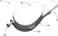
- FIGS. 1 A, 1 B, 2 A, and 2 B depict a dermal patch system in accordance with an exemplary embodiment
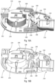
- FIGS. 3 A, 3 B, 4 A, and 4 B depict the dermal patch system without a cover in accordance with an exemplary embodiment
- FIGS. 5 A, 5 B, 6 A, and 6 B depict a cartridge of the dermal patch system in accordance with an exemplary embodiment
- FIGS. 7 A and 7 B- 13 A and 13 B depict a cover of the dermal patch system in accordance with an exemplary embodiment
- FIGS. 14 A and 14 B- 23 depict a base of the dermal patch system in accordance with an exemplary embodiment
- FIGS. 24 A and 24 B- 26 depict a vial guide of the base of the dermal patch system in accordance with an exemplary embodiment
- FIGS. 27 A and 27 B- 29 A and 29 B depict a handle retention feature of the base of the dermal patch system in accordance with an exemplary embodiment
- FIGS. 30 A and 30 B- 33 A and 33 B depict a microneedle array housing of the dermal patch system in accordance with an exemplary embodiment
- FIGS. 34 A and 34 B- 36 depict the cartridge of the dermal patch system without the cover and without the pump assembly in accordance with an exemplary embodiment
- FIGS. 37 A and 37 B depict a pull mechanism of the cartridge of the dermal patch system in accordance with an exemplary embodiment
- FIGS. 38 A, 38 B, 39 A, and 39 B depict a handle of the pull mechanism in accordance with an exemplary embodiment
- FIGS. 40 A, 40 B, 41 A, and 41 B depict a pump assembly of the cartridge of the dermal patch system in accordance with an exemplary embodiment
- FIGS. 42 A and 42 B- 45 A and 45 B depict a trigger portion of the pump assembly of the cartridge of the dermal patch system in accordance with an exemplary embodiment
- FIGS. 46 A and 46 B- 50 A and 50 B depict a pump portion of the pump assembly of the cartridge of the dermal patch system in accordance with an exemplary embodiment
- FIGS. 51 A, 51 B, 52 A, and 52 B depict a microneedle array assembly of the cartridge of the dermal patch system in accordance with an exemplary embodiment
- FIGS. 53 A and 53 B- 56 A and 56 B depict a microneedle array holder of the microneedle array assembly in accordance with an exemplary embodiment
- FIG. 57 depicts an adhesive film of the microneedle array holder in accordance with an exemplary embodiment
- FIGS. 58 A and 58 B- 61 A and 61 B depict a microneedle array of the microneedle array assembly in accordance with an exemplary embodiment
- FIGS. 62 A and 62 B depict the microneedle array holder with the adhesive film in accordance with an exemplary embodiment
- FIGS. 63 A and 63 B- 67 A and 67 B depict a retraction button of the cartridge of the dermal patch system in accordance with an exemplary embodiment
- FIGS. 68 A and 68 B- 70 A and 70 B depict a trigger of the cartridge of the dermal patch system in accordance with an exemplary embodiment
- FIG. 71 depicts a retraction button of the cartridge contacting a microneedle array assembly of the cartridge in accordance with an exemplary embodiment
- FIG. 72 depicts a ball of a pump assembly of the cartridge in a first position within the pump assembly in accordance with an exemplary embodiment
- FIG. 73 depicts a ball of a pump assembly of the cartridge in a second position within the pump assembly in accordance with an exemplary embodiment
- FIG. 74 depicts a trigger and a trigger portion of the pump assembly of the cartridge in a first position in accordance with an exemplary embodiment
- FIG. 75 depicts a trigger and a trigger portion of the pump assembly of the cartridge in a second position in accordance with an exemplary embodiment
- FIG. 76 depicts a microneedle array of the cartridge in an undeployed position in accordance with an exemplary embodiment
- FIG. 77 depicts a microneedle array of the cartridge in a deployed position in accordance with an exemplary embodiment
- FIG. 78 depicts a microneedle array of the cartridge in a deployed position in accordance with an exemplary embodiment
- FIG. 79 depicts the microneedle array of the cartridge in a retracted position in accordance with an exemplary embodiment
- FIG. 80 depicts the cartridge of the dermal patch system with a piezoelectric pump in accordance with an exemplary embodiment
- FIG. 81 depicts a dermal patch system with a quick response (“QR”) code and a computer system that is in communication with an electronic medical record (“EMR”) database in accordance with an exemplary embodiment
- FIG. 82 schematically depicts a computer system in accordance with an exemplary embodiment
- FIG. 83 schematically depicts a cloud computer environment in accordance with an exemplary embodiment.
- FIG. 84 is a flow chart of a method for administering a pharmaceutical to a subject in accordance with an exemplary embodiment.
- the present disclosure generally relates to a dermal patch that may be utilized to deliver a pharmaceutical to a subject.
- a dermal patch may be used to deliver a pharmaceutical via a vial that can be attached to the dermal patch.
- Dermal patches disclosed herein may allow for the delivery of a pharmaceutical in a variety of environments (e.g., in the home, in the field, in a medical facility, etc.).
- substantially refers to a deviation, if any, of at most 10% from a complete state and/or condition.
- subject refers to a human subject or an animal subject (i.e., chicken, pig, cattle, dog, cat, etc.).
- pharmaceutical refers to a substance that is used in diagnosis, treatment, or prevention of a disease or a substance that restores, corrects, or modifies a biological function.
- fractional dose refers to a dose of a pharmaceutical, particularly a vaccine, that is a fraction of a standard dose of that pharmaceutical (e.g., one-fifth, two-thirds, three-fourths, etc.) administered by a same or an alternative route (e.g., intradermally rather than subcutaneously or intramuscular, etc.).
- a standard dose of a vaccine includes a 100 ⁇ g dose
- a fractional dose of that vaccine may include a 20 ⁇ g dose, a 25 ⁇ g dose, a 50 ⁇ g dose, a 75 ⁇ g dose, etc.
- fractional dose vaccination may reduce a number of infections within a population while administering only a fraction of the dose of the vaccine to a number of subjects which in turn may allow more individuals to become vaccinated.
- transparent indicates that light can substantially pass through an object (e.g., a window) to allow visualization of a material disposed behind the object.
- a transparent object allows the passage of at least 70%, or at least 80%, or at least 90% of visible light therethrough.
- needle refers to a component with a pointed tip that is configured to pierce an outer surface of an element (e.g., skin of a subject) to provide a passageway through the skin.
- a needle can be hollow to allow a fluid (e.g., a pharmaceutical) to pass therethrough.
- microneedle refers to micron scaled needles used to administer a pharmaceutical.
- a microneedle can have length between about 1 mm and about 3 mm.
- the microneedles can administer a pharmaceutical to a subject at a rate of about 250 ⁇ l/min per microneedle.
- a microneedle can have a diameter between about 50 and about 350 microns wide or can have a gauge between 28 and 36 and can have a tip thickness between about 1 and about 25 microns.
- tube refers to hollow cylinder that provides a fluidic channel for transporting liquids or gases.
- a device which is herein also referred to as a dermal patch or a dermal patch system, for delivering a pharmaceutical to a subject.
- a dermal patch system can include a cartridge that can be affixed to a subject's skin (e.g., via an adhesive layer), a separate vial containing a pharmaceutical can be attached to the cartridge and an at least one microneedles and more typically an array of microneedles disposed within the cartridge can be deployed to puncture the subject's skin and deliver the pharmaceutical to the subject.
- the microneedles deliver the pharmaceutical intradermally.
- the dermal patch system is configured to deliver a single fractional dose of the pharmaceutical stored within the vial.
- the cartridge includes a pull mechanism that deploys the microneedle array and causes the cartridge to pump a dose of the pharmaceutical into the subject via the deployed microneedles.
- the cartridge can also include a push button mechanism. After a user administers the pharmaceutical, the user can push the push button mechanism into the cartridge which causes the microneedle array to retract into the cartridge which in turn allows the user to remove the cartridge from the subject. In this manner, the dermal patch system remains safe before it is engaged and after delivery of the pharmaceutical as in both cases the microneedle array is retained within the cartridge.
- the pull mechanism cannot be pulled unless the dermal patch system has a proper orientation on a subject's skin (e.g., a substantially vertical position).
- the dermal patch system may administer the pharmaceutical only when the dermal patch has a given orientation.
- Providing a dermal patch system that administers a pharmaceutical when in a specific orientation may ensure that the subject receives all or substantially all of the pharmaceutical from a vial as the dermal patch may be aided by gravity when administering the pharmaceutical.
- the dermal patch system 10 includes a cartridge 12 that can be affixed to a subject's skin via an adhesive layer.
- the dermal patch system 10 also includes a vial 14 that contains a pharmaceutical.
- the vial 14 can be inserted into the cartridge 12 for delivery of the pharmaceutical stored therein.
- the vial 14 includes a single fractional dose of a pharmaceutical. More particularly, in some embodiments, the vial 14 includes a single fractional dose of a vaccine.
- the cartridge 12 includes a cover 100 and a base 200 that can couple to the cover 100 .
- the cover 100 and the base 200 can be formed as two separate components that are removably coupled to one another (e.g., via a snap fitting).
- the cover 100 and the base 200 form an integral unitary cartridge 12 .
- the cover 100 can be coupled to the base 200 via an adhesive, laser welding, etc.
- the cartridge 12 may be formed using a variety of suitable materials including, but not limited to, polymeric materials (e.g., polyolefins, polyethylene terephthalate (PET), polyurethanes, polynorbornenes, polyethers, polyacrylates, polyamides (Polyether block amide also referred to as Pebax®), polysiloxanes, polyether amides, polyether esters, trans-polyisoprenes, polymethyl methacrylates (PMMA), cross-linked trans-polyoctylenes, cross-linked polyethylenes, cross-linked polyisoprenes, cross-linked polycyclooctenes, inorganic-organic hybrid polymers, co-polymer blends with polyethylene and Kraton®, styrene-butadiene co-polymers, urethane-butadiene co-polymers, polycaprolactone or oligo caprolactone co-polymers, polylactic acid (PLLA) or polyl
- the cartridge 12 also includes a pull mechanism 300 , a pump assembly 400 coupled to the pull mechanism 300 , a microneedle array assembly 500 , a retraction button 600 , and a trigger 700 .
- the pull mechanism 300 when pulled, the pull mechanism 300 causes the trigger 700 to release the microneedle array assembly 500 thereby allowing microneedle array assembly 500 to move to a deployed position to puncture the skin of a subject.
- the pull mechanism 300 causes the pump assembly 400 to pump the pharmaceutical from the vial 14 (when the vial 14 is coupled to the cartridge 12 ) through the microneedle array assembly 500 into the subject.
- a user can push the retraction button 600 , which causes the microneedle array assembly 500 to retract into the cartridge 12 which allows the dermal patch system 10 to be removed from the subject.
- Providing dermal patch system 10 which places the microneedle array assembly 500 in a stored position before and after use keeps the dermal patch system 10 in a safe state. In other words, the microneedle array assembly 500 is securely retained within the cartridge 12 when the cartridge is not in use.
- the cover 100 is shown in accordance with an exemplary embodiment.
- the cover 100 includes a top wall 102 and a side wall 104 .
- the side wall 104 extends vertically from and perpendicular to the top wall 102 .
- the top wall 102 extends longitudinally from and perpendicular to the side wall 104 .
- the top wall 102 includes an outer surface 102 a and an opposed inner surface 102 b .
- the side wall 104 includes an outer surface 104 a and an opposed inner surface 104 b.
- the cover 100 includes a first vial guide 106 which includes an outer wall 108 and an inner end wall 110 .
- the outer wall 108 includes an outer surface 108 a and an opposed inner surface 108 b .
- the end wall 110 includes an outer surface 110 a and opposed inner surface 110 b .
- the outer wall 108 extends longitudinally from and perpendicular to the outer surface 104 a of the side wall 104 and the outer surface 110 a of the end wall 110 .
- At least a portion of the inner surface 108 b of outer wall 108 of the vial guide 106 has a similar shape and dimension as the outer surface of the vial 14 such that a portion of the outer surface of the vial 14 contacts the inner surface 108 b .
- the end wall 110 defines a U-shaped opening 112 .
- the cover 100 further includes a first handle retention element 114 which includes an outer surface 114 a and an inner surface 114 b .
- the outer surface 114 a of the first handle retention element 114 extends from and perpendicular to the outer surface 104 a of the side wall 104 .
- the inner surface 114 b of the first handle retention element 114 includes a first groove 116 , a second groove 118 , and a third groove 120 .
- the first handle retention element 114 extends vertically from and perpendicular to the inner surface 102 b of the top wall 102 .
- the first handle retention element 114 also includes protrusions 122 . As will be discussed in further detail herein, the protrusions 122 aid in coupling the cover 100 to the base 200 .
- the cover 100 also includes a retraction button opening 124 and retraction button guides 126 .
- the retraction button opening 124 extends through the side wall 104 . That is, the retraction button opening 124 extends between the outer surface 104 a and the inner surface 104 b of the side wall 104 .
- the retraction button guides 126 extend longitudinally from and perpendicular to the inner surface 104 b of the side wall 104 and extend vertically from and perpendicular to the inner surface 102 b of the top wall 102 .
- the retraction button guides 126 are aligned with the retraction button opening 124 within the cover 100 .
- the cover 100 further includes a plurality of locking members 128 that extend longitudinally from and perpendicular to the inner surface 104 b of the side wall 104 . As will be discussed in further detail herein, the locking members 128 couple the cover 100 to the base 200 .
- the cover 100 also includes a circular retention member 130 and a latch guide 132 . The circular retention member 130 and the latch guide 132 extend vertically from and perpendicular to the inner surface 102 b of the top wall 102 .
- the base 200 is shown in accordance with an exemplary embodiment.
- the base 200 includes a bottom wall 202 with a top surface 202 a and an opposed bottom surface 202 b .
- the bottom wall 202 and the side wall 104 have the same perimeter shape such that when the cover 100 is coupled to the base 200 , the cover 100 is flush with the base 200 . Furthermore, when the cover 100 is coupled to the base 200 the side wall 104 of the cover 100 contacts the top surface 202 a of the bottom wall 202 .
- the base 200 further includes a plurality of extensions 206 that extend vertically from and perpendicular to the top surface 202 a of the bottom wall 202 . The extensions 206 and the bottom wall 202 define gaps 208 .
- gaps, and therefore the extensions 206 are shaped and dimensioned to accept a locking member 128 of the cover 100 such that an extension 206 couples to a locking member 128 via a snap fitting.
- the gaps 208 extend through the bottom wall 202 which provides access to an inner volume of the cartridge 12 .
- the base 200 further includes a second vial guide 210 .
- the second vial guide 210 includes an outer wall 212 and an inner end wall 214 .
- the outer wall 212 includes an outer surface 212 a and an opposed inner surface 212 b .
- the end wall 214 includes an outer surface 214 a and an opposed inner surface 214 b . At least a portion of the inner surface 212 b of the outer wall 212 has a similar shape and dimension to the outer surface of the vial 14 such that a portion of the outer surface of the vial 14 contacts the inner surface 212 b of the outer wall 212 .
- the end wall 214 defines a U-shaped opening 216 .
- the second vial guide 210 also includes a latch 218 , a gap 220 , and a protrusion 222 .
- the latch 218 extends longitudinally from the outer wall 212 towards a center of the second vial guide 210 .
- the gap 220 is defined by the outer wall 212 .
- the latch 218 extends at least partially across the gap 220 .
- the protrusion 222 extends vertically from the inner surface 212 b of the outer wall 212 and extends longitudinally from the outer surface 214 a of the end wall 214 .
- the first vial guide 106 and the second vial guide 210 have a similar shape and dimension and align with one another when the cover 100 is coupled to the base 200 . Together, the first vial guide 106 and the second vial guide 210 are referred to as a vial receptacle. Similarly, the end walls 110 and 214 have a similar shape and dimension such that when the cover 100 is coupled to the base 200 the end walls 110 and 214 align and the openings 112 and 216 together define an aperture that provides access to the inner volume of the cartridge 12 .
- the outer surface 108 a of the wall 108 of the first vial guide 106 and the outer surface 212 a of the outer wall 212 of the second vial guide 210 have a similar shape and dimension such that when the cover 100 is coupled to the base 200 , the outer walls 108 and 212 form a uniform cylinder that extends outwardly from the cartridge 12 .
- the inner surface 108 b of the outer wall 108 and the inner surface 212 b of the outer wall 212 also have a similar shape and dimension such that the inner surfaces 108 b and 212 b align when the cover 100 is coupled to the base 200 .
- the inner surfaces 108 b and 212 b with the outer surfaces 110 a and 214 a define an inner chamber of the vial receptacle.
- the cartridge 12 includes a stop 16 that is generally cylindrical in shape.
- the stop 16 may be formed of a polymeric or an elastomeric material.
- the stop 16 is disposed within the inner volume of the vial receptacle and is held in place by the protrusion 222 .
- a portion of the inner surface 108 b of the outer wall 108 and a portion of the inner surface 212 b of the outer wall 212 has a similar shape and dimension as the outer surface of the stop 16 such that the inner surfaces 108 b and 212 b retain the stop 16 within the vial receptacle.
- the stop 16 when the stop 16 is disposed within the inner volume of the vial receptacle, the stop 16 contacts portions of the inner surfaces 108 b and 212 b and contacts the outer surfaces 110 a and 214 a of the end walls 110 and 214 respectively. Furthermore, when the cover 100 is coupled to the base 200 , a portion of the stop 16 extends through the aperture defined by the end walls 110 and 214 .
- the cartridge 12 includes a first hollow needle 18 and a second hollow needle 20 that extend through the stop 16 .
- the needles 18 and 20 pierce a cap of the vial 14 to provide access to a pharmaceutical stored therein.
- the latch 218 is compressed into the gap 220 m which allows the vial 14 to extend into the vial receptacle until the end of the vial 14 contacts the stop 16 .
- the latch 218 returns to its original position. In this position, when the vial 14 is pulled, the cap of the vial 14 contacts the latch 218 which prevents the vial 14 from being removed from the cartridge 12 .
- the base 200 further includes a second handle retention element 224 .
- second handle retention element 224 includes an outer surface 224 a and an opposed inner surface 224 b .
- the inner surface 224 b of the second handle retention element 224 includes a first groove 226 , a second groove 228 , and a third groove 230 .
- the second handle retention element 224 extends vertically from and perpendicular to the top surface 202 a of the bottom wall 202 .
- the second handle retention element 224 includes cavities 232 .
- the first handle retention element 114 and the second handle retention element 224 have a similar shape and dimension and align with one another when the cover 100 is coupled to the base 200 . Together, the first handle retention element 114 and the second handle retention element 224 are referred to as a handle receptacle. Furthermore, when the cover 100 is coupled to the base 200 , the first handle retention element 114 and the second handle retention element 224 align such that the handle receptacle has an outer opening and inner opening which allows at least a portion of the pull mechanism to extend through the handle receptacle.
- the outer surface 114 a of the first handle retention element 114 and the outer surface 224 a of the second handle retention element 224 have a similar shape and dimension such that when the cover 100 is coupled to the base 200 , the outer surfaces 114 a and 224 a form a uniform cylinder that extends outwardly from the cartridge 12 .
- the inner surface 114 b and the inner surface 224 b also have a similar shape and dimension such that the inner surfaces 114 b and 224 b align when the cover 100 is coupled to the base 200 . Together, the inner surfaces 114 b and 224 b define an inner chamber of the handle receptacle.
- first grooves 116 and 226 have a similar shape and dimension
- the second grooves 118 and 228 have a similar shape and dimension
- the third grooves 120 and 230 have a similar shape and dimension.
- the base 200 further includes a first tube guide 234 and a second tube guide 236 that extend vertically from and the top surface 202 a of the bottom wall 202 .
- the cartridge 12 includes a first tube 22 and a second tube 24 .
- the first tube guide 234 retains the first tube 22 and the second tube guide 236 retains the second tube 24 within the cartridge 10 .
- the tube guides 234 and 236 direct the tubes 22 and 24 around a portion of the pump assembly 400 ( FIGS. 3 A and 3 B ).
- the first tube guide 234 directs the first tube 22 towards the microneedle array assembly 500 .
- the first tube 22 and the second tube 24 fit around the first needle 18 and the second needle 20 respectively. As such, the tubes 22 and 24 are in open communication with the vial 14 via the needles 18 and 20 . In other embodiments, the second tube 24 may be omitted. In these embodiments, air may enter the vial 14 via the second needle 20 .
- the base 200 further includes retention aperture 238 that extends through the bottom wall 202 .
- the retention aperture 238 extends between the top surface 202 a and the bottom surface 202 b of the bottom wall 202 .
- the retention aperture 238 is disposed vertically below the circular retention member 130 .
- the circular retention member 130 and the retention aperture 238 aid in coupling the pump assembly to the cover 100 and the base 200 .
- the base 200 also includes a latch 240 that extends vertically from and perpendicular to a portion of the first tube guide 234 .
- the latch 240 allows the pump to pump the pharmaceutical from the vial and to the microneedle assembly 400 .
- the latch 240 allows the pump assembly 400 to rotate in a clockwise direction and prevents the pump assembly 400 from rotating in a counterclockwise direction. Rotating in the counterclockwise direction would result in the pump assembly 400 failing to pump the pharmaceutical.
- the base 200 further includes a microneedle array aperture 242 and a microneedle array housing 244 .
- the microneedle array aperture 242 extends through the bottom wall 202 . That is, the microneedle array aperture 242 extends between the top surface 202 a and the bottom surface 202 b of the bottom wall 202 .
- the microneedle array aperture 242 is shaped and dimensioned to allow a portion of the microneedle array assembly 500 to extend through the bottom wall 202 .
- the microneedle array housing 244 is generally cylindrical in shape and is shaped and dimensioned to house the microneedle array assembly 500 . While the microneedle array housing 244 and the microneedle array assembly 500 are depicted as being cylindrical, it is understood that the microneedle array housing 244 and the microneedle array assembly 500 may have a different shape.
- the microneedle array housing 244 extends vertically from and perpendicular to the top surface 202 a of the bottom wall 202 .
- the microneedle array housing 244 includes a side wall 246 and a top wall 248 . The side wall 246 extends vertically between and perpendicular to the top surface 202 a of the bottom wall 202 and the top wall 248 .
- the top wall 248 extends longitudinally between the side wall 246 .
- the side wall 246 includes an outer surface 246 a and an opposed inner surface 246 b .
- the top wall 248 includes an outer surface 248 a and an opposed inner surface 248 b.
- the microneedle array housing 244 and the bottom wall 202 include a first extension opening 250 and a second extension opening 252 that are positioned on opposite sides of the microneedle array housing 244 .
- the extension openings 250 and 252 extend through the walls 246 and 248 . That is, the extension openings 250 and 252 extend between the outer surface 246 a and the inner surface 246 b of the side wall 246 , extend between the surfaces 248 a and 248 b of the top wall 248 , and extend between the top surface 202 a and the bottom surface 202 b of the bottom wall 202 .
- the microneedle array housing 244 further includes an opening 254 that is positioned between the extension openings 250 and 252 .
- the opening 254 extends through the side wall 246 and the top wall 248 . That is, the opening 254 extends between the surfaces 246 a and 246 b of the side wall 246 and extends between the surfaces 248 a and 248 b of the top wall 248 .
- the microneedle array housing 244 also includes a first tensioner opening 256 and a second tensioner opening 258 that are aligned with one another.
- a portion of the first tensioner opening 256 extends through the side wall 246 and another portion of the first tensioner opening 256 extends through the bottom wall 202 . That is, the first tensioner opening 256 extends between the outer surface 246 a and the inner surface 246 b of the side wall 246 and extends between the top surface 202 a and the bottom surface 202 b of the bottom wall 202 .
- the second tensioner opening 258 extends through the top wall 248 of the microneedle array housing 244 . That is, the second tensioner opening 258 extends between the outer surface 248 a and the inner surface 248 b of the top wall 248 .
- the top wall 248 of the microneedle array housing 244 also includes a microneedle array assembly aperture 260 that extends through the top wall 248 of the microneedle array housing 244 . That is, the microneedle array assembly aperture 260 extends between the outer surface 246 a and the inner surface 246 b of the wall 246 .
- the top wall 248 of the microneedle array housing 244 also includes a first and second trigger guide 262 .
- the trigger guides 262 extend vertically from and perpendicular to the outer surface 248 a of the top wall 248 .
- the trigger guides 262 are positioned on opposite sides of the microneedle array assembly aperture 260 .
- the microneedle array housing 244 further includes a first partially circular projection 264 and a second partially circular projection 266 that extend vertically from and perpendicular to the inner surface 248 b of the top wall 248 .
- the base 200 includes a first button guide 270 and a second button guide 272 that extend vertically from and perpendicular to the top surface 202 a of the bottom wall 202 .
- the first and second button guides 270 and 272 extend along opposite sides of the microneedle array housing 244 .
- the first button guide 270 extends along the first extension opening 250 and the second button guide 272 extends along the second extension opening 252 .
- the first and second button guides 270 and 272 direct a portion of the retraction button 600 towards the first extension opening 250 and second extension opening 252 .
- the base 200 further includes a third button guide 274 .
- the third button guide 274 extends vertically from and perpendicular to the top surface 202 a of the bottom wall 202 .
- the third button guide 274 is disposed between the first and second button guides 270 and 272 and is aligned with the opening 254 of the microneedle array housing 244 .
- the third button guide 274 directs a portion of the retraction button 600 towards the opening 254 .
- the pull mechanism 300 includes a handle 302 and a cord 304 that is connected to the handle 302 .
- the handle 302 includes a grip 306 , a ball retention feature 308 , and an anchor portion 310 .
- the grip 306 defines a distal end of the handle 302 and the ball retention feature 308 defines a proximal end of the handle 302 .
- the ball retention feature 308 includes a rounded inner surface 312 , a cylinder 314 and an angled surface 316 .
- the rounded inner surface 312 , the cylinder 314 , and the angled surface 316 are shaped and dimensioned to retain a ball 21 of the cartridge 12 when the cartridge 12 is in a given orientation and is shaped and dimensioned to release the ball 21 when the cartridge 12 is in any other orientation.
- the ball retention feature 308 includes a first outer surface 318 and a second outer surface 320 .
- the outer surfaces 318 and 320 have a similar shape and dimensioned as the first handle retention grove and the second handle retention grove which allows the handle retention features 114 and 224 to retain the handle 302 of the pull mechanism 300 .
- the anchor portion 310 includes an aperture 322 that extends through the anchor portion 310 .
- the cord 304 extends through the aperture 322 which allows securing the cord 304 to the anchor portion 310 .
- the pump assembly 400 is shown in accordance with an exemplary embodiment.
- the pump assembly 400 includes a trigger portion 402 and a pump portion 404 that are coupled to one another.
- the pump assembly 400 also includes a ball 406 that is disposed between the trigger portion 402 and the pump portion 404 .
- the trigger portion 402 includes a base 408 with a top surface 408 a and an opposed bottom surface 408 b .
- the base 408 includes an aperture 410 that extends through the base 408 . That is, the aperture 410 extends between the top surface 408 a and the bottom surface 408 b .
- the trigger portion 402 further includes a latch 412 which extends vertically from and perpendicular to the top surface 408 a of the base 408 .
- the latch 412 includes a circular portion 414 and an extension 416 .
- the circular portion extends circumferentially around the aperture 410 and the extension 416 extends longitudinally from and perpendicular to the circular portion 414 .
- the bottom surface 408 b of the base 408 defines a spiral groove 418 .
- the spial groove 418 is shaped and dimensioned to retain the ball 406 therein.
- the pump portion 404 includes a top portion 420 , a middle support portion 422 , a ratchet 424 , and a cog 426 .
- the top portion 420 includes a base 428 with a top surface 428 a and an opposed bottom surface 428 b .
- the top portion 420 further includes a top cylinder 430 that extends vertically from and perpendicular to the top surface 428 a of the base 428 .
- the top cylinder 430 extends through the aperture 410 and beyond the circular portion 414 of the latch 412 .
- the top cylinder 430 extends into the circular retention member 130 of the cover 100 which aids in coupling the pump assembly 400 to the cover 100 .
- the circular retention member 130 maintains the pump assembly 400 in a given position while allowing the pump assembly 400 to rotate.
- the top surface 428 a of the base 428 defines a spiral groove 432 that is shaped and dimensioned to retain the ball 406 therein.
- the base 408 of the trigger portion 402 has a similar shape and dimension as the base 428 .
- the spiral groove 418 of the base 408 and the spiral groove 432 of the base 428 have a similar shape and dimension and when the trigger portion 402 is coupled to the pump portion 404 , the spiral grooves 418 and 432 align with one another and retain the ball 406 therebetween. Together, the spiral groove 418 and the spiral groove 432 are referred to as a spiral ball retention groove.
- the middle support portion 422 includes an aperture 434 that extends longitudinally through the middle support portion 422 .
- the aperture 434 is shaped and dimensioned to accept the cord 304 of the pull mechanism 300 which allows the cord 304 to detachably couple to the pump assembly 400 .
- the cord 304 wraps around the middle support portion 422 .
- the ratchet 424 includes a top surface 424 a and an opposed bottom surface 424 b . Furthermore, the middle support portion 422 extends vertically between the bottom surface 428 b of the base 428 and the top surface 424 a of the ratchet 424 .
- the ratchet 424 also includes a plurality of teeth 436 that extend circumferentially around the ratchet 424 and extends vertically between the top surface 424 a and the bottom surface 424 b . Each tooth 436 includes a vertical surface 438 and an angled surface 440 . As depicted in FIGS. 3 A and 3 B , the latch 240 is disposed between two teeth 436 .
- the cog 426 extends vertically from and perpendicular to the bottom surface 424 b of the ratchet 424 .
- the cog 426 includes a bottom surface 426 a and the pump portion 404 includes a bottom cylinder 442 that extends vertically from and perpendicular to the surface 426 a of the cog 426 .
- the bottom cylinder 442 extends into the retention aperture 238 of the base 200 which aids in coupling the pump assembly 400 to the base 200 and maintains the pump assembly 400 in a given position while allowing the pump assembly 400 to rotate.
- the cog 426 includes a plurality protrusions 444 . As will be discussed in further detail herein, when the pump assembly 400 rotates, the cog 426 acts as a peristaltic pump as the protrusions force a pharmaceutical through the first tube 22 via positive displacement.
- the microneedle array assembly 500 is shown in accordance with an exemplary embodiment.
- the microneedle array assembly 500 includes a microneedle array holder 502 , an adhesive film 504 , and a microneedle array platform 506 .
- the microneedle array holder 502 includes a circular base 508 extensions 510 , a hollow cylinder 512 , a circular projection 514 , and a T-shaped column 516 .
- the base 508 includes a top surface 508 a , an opposed bottom surface 508 b , and a side surface 508 c that extends vertically between and perpendicular to the top surface 508 a and the bottom surface 508 b .
- the base 508 further includes a first circular opening 518 and a second circular opening 520 positioned on opposing sides of the circular projection 514 .
- the base 508 also includes a circular aperture 522 that is positioned adjacent to an extension 510 .
- the openings 518 and 520 and the circular aperture 522 extend through the base 508 . That is the openings 518 and 520 and the circular aperture 522 extend between the top surface 508 a and the bottom surface 508 b of the base 508 .
- the extensions 510 include a vertical portion 524 and a horizontal portion 526 .
- the vertical portion 524 extends longitudinally from and perpendicular to the side surface 508 c of the base 508 and extends vertically from and perpendicular to the top surface 508 a of the base 508 .
- the horizontal portion 526 extends longitudinally from and perpendicular to the vertical portion 524 .
- the hollow cylinder 512 extends vertically from and perpendicular to the top surface 508 a of the base 508 . Furthermore, the hollow cylinder 512 extends circumferentially around the circular aperture 522 such that an opening extends through the hollow cylinder 512 and through the base 508 .
- the circular projection 514 extends vertically from and perpendicular to the top surface 508 a of the base 508 and surrounds the T-shaped column 516 .
- the cartridge 12 includes an injection spring 26 that extends around the circular projection 514 .
- the injection spring 26 aids in moving the microneedle array assembly 500 from an undeployed position to a deployed position.
- the adhesive film 504 couples the microneedle array holder 502 to the microneedle array platform 506 and includes top surface and an opposed bottom surface.
- the top surface attaches to the microneedle array holder 502 and the bottom surface attaches to the microneedle array platform 506 .
- the adhesive film 504 further includes a first opening 528 , a second opening 530 , and a third opening 532 .
- the first opening 518 and the second opening 520 of the base 508 align with the first opening 528 and the second opening 530 of the film 504 respectively. Furthermore, when the adhesive film 504 is attached to the bottom surface of the base 508 of the microneedle array holder 502 , the aperture 522 of the base 508 aligns with the third opening 532 of the film 504 .
- the microneedle array platform 506 is shown in accordance with an exemplary embodiment.
- the microneedle array platform 506 includes a base 534 that supports a plurality of hollow microneedles 536 .
- the base 534 of the microneedle array platform 506 includes a top surface 534 a and an opposed bottom surface 534 b .
- the plurality of microneedles 536 extend vertically from and perpendicular to the bottom surface 534 b .
- the microneedles 536 are hollow such that the microneedles 536 include a lumen that extends through the base 534 such that an end of a microneedle 536 is in open communication with the top surface 534 a of the base 534 .
- the top surface 534 a of the base 534 defines an open fluidic channel 538 (e.g., a microfluidic channel) that includes a first portion 538 a , a second portion 538 b , a third portion 538 c and a similar fourth portion 538 d .
- the first portion 538 a is generally linear
- the second portion 538 b extends in a T-junction from the first portion 538 a
- the third portion 538 c and the fourth portion 538 d extend from the second portion 538 b .
- the third portion 538 c and the fourth portion 538 d extend around the circumference of the base 534 .
- the openings of the lumens of the microneedles 536 extend to the third portion 538 c and the fourth portion 538 d of the open fluidic channel 538 .
- the lumens of the microneedles 536 are in open communication with the first portion 538 a of the fluidic channel 538 via the second portion 538 b , third portion 538 c , and the fourth portion 538 d.
- the base 534 further includes a first extension 540 and a second extension 542 that extend vertically from and perpendicular to the top surface 534 a of the base 534 .
- first extension 540 extends through the first opening 528 and the second extension 542 extends through the second opening 530 of the adhesive film 504 .
- the first extension 540 extends through the first circular opening 518 and the second circular opening 520 of the base 534 of the microneedle array platform 506 respectively.
- the adhesive film 504 may be omitted and, in such an embodiment, the microneedle array holder 502 may be coupled to the microneedle array platform 506 via ultrasonic welding.
- the adhesive film 504 covers the top surface 534 a of the base 534 .
- the opening 532 is disposed vertically above a segment of the first portion 538 a of the fluidic channel 538 which seals all but this portion of the fluidic channel 538 .
- the opening 532 of the adhesive film 504 (and therefore a portion of the first portion 538 a of the fluidic channel 538 ) is positioned vertically below the circular aperture 522 .
- the fluidic channel 538 is in open communication with the aperture 522 .
- FIGS. 34 A, 34 B, 35 A, and 35 B when the cartridge 12 is assembled, the first tube 22 is connected to the hollow cylinder 512 and as such, the first tube 22 is in open communication with the fluidic channel 538 via the hollow cylinder 512 .
- the dermal patch system 10 delivers the pharmaceutical to a subject via the microneedles 536 .
- an equal number of microneedles 536 are disposed on opposite sides of an end of the second portion 538 b . That is, as depicted in FIGS. 59 A and 59 B , three microneedles are disposed on one side of the second portion 538 b and three microneedles 536 are disposed on the opposite side of the second portion 538 b of the fluidic channel 538 .
- Providing the same number of microneedles 536 on opposite ends of the second portion 538 b of the fluidic channel 538 allows substantially the same amount of pharmaceutical to flow through each microneedle 536 at about a same flow rate (e.g., about 1300 ⁇ l/min).
- the dermal patch system 10 is depicted as including twelve microneedles 536 , in other embodiments, the dermal patch system may include more or less microneedles 536 each in communication with the fluidic channel 538 .
- the microneedles 536 may have the same or varied length.
- the length of the microneedles may be in a range of about 1 mm-about 3 mm.
- the length of the microneedles 536 determines a depth into the dermis of the subject that the pharmaceutical is delivered.
- subjects may have varying depths of dermal layers.
- the epidermis of one subject may be thicker or thinner compared to the epidermis of another subject.
- Providing a dermal patch system 10 with microneedles 536 of varying lengths may ensure that a pharmaceutical is delivered to the dermis of a subject as at least one of the microneedles 536 may extend through the epidermis of the subject.
- the lengths of the microneedles 536 may be varied by a factor in a range of at least 10% to about 20%.
- the microneedles 536 may have a length between about 1 mm and about 2 mm.
- the microneedles 536 may have a length between about 2 mm and about 3 mm.
- the retraction button 600 includes a U-shaped base 602 and a vertical button portion 604 that extends vertically from and perpendicular to the U-shaped base 602 .
- the U-shaped base 602 includes a first arm 606 and a second arm 608 .
- the first arm 606 and the second arm 608 include an angled surface 610 and 612 respectively.
- the U-shaped base 602 has a shape that is similar to the shape of the microneedle array housing 244 such that the first arm 606 and the second arm 608 extend around microneedle array housing 244 .
- the retraction button 600 further includes a blocking feature 614 .
- the blocking feature 614 extends vertically from and perpendicular to the U-shaped base 602 and extends longitudinally from and perpendicular to the vertical button portion 604 .
- the retraction button 600 further includes a gap 616 that extends through the U-shaped base 602 and the vertical button portion 604 .
- the gap 616 is shaped and dimensioned to extend over the third button guide 274 .
- the cartridge 12 further includes a trigger 700 .
- the trigger 700 includes a notch 702 that is defined by a first surface 704 and a second surface 706 .
- the trigger 700 further includes a first outer wall 708 and a second outer wall 710 that is parallel to the first outer wall 708 .
- the trigger 700 also includes a first bottom wall 712 and a second bottom wall 714 that extend between the first outer wall 708 and the second outer wall 710 .
- the first bottom wall 712 and the second bottom wall 714 define a T-shaped opening 716 that also extends between the first outer wall 708 and the second outer wall 710 .
- the trigger 700 When the trigger 700 is inserted into the cartridge 12 , a portion of the bottom surface of the trigger 700 rests upon the outer surface 248 a of the microneedle array housing 244 and another portion of the bottom surface of the trigger 700 rests upon the top surface 408 a of the trigger portion 402 of the pump assembly 400 . Furthermore, the first outer wall 708 and the second outer wall 710 are disposed between the first and second trigger guides 262 .
- the cartridge 12 is moveable between an undeployed position ( FIGS. 3 A and 3 B ) to a deployed position ( FIGS. 77 and 78 ).
- the handle 302 of the pull mechanism 300 is disposed within the handle receptacle of the cartridge 12 and the cord 304 of the pump assembly 400 extends through the aperture 434 and wraps around the middle support portion 422 of the pump assembly 400 .
- the cartridge 12 includes a tensioner 28 .
- the tensioner 28 extends through the first tensioner opening 256 and the second tensioner opening 258 of the microneedle array housing 244 which allows the tensioner 28 to couple to the microneedle array housing 244 .
- the tensioner 28 includes an aperture that allows the cord 304 to extend therethrough. As further depicted in FIGS.
- the tensioner 28 when the cartridge 12 is in the undeployed position, the tensioner 28 causes the portion of the cord 304 that wraps around middle support portion 422 of the pump assembly 400 to be taut while portion of the cord 304 that is between the handle 302 and the tensioner 28 has some slack.
- the extension 416 of the pump assembly 400 is disposed within the notch 702 such that the extension 416 contacts the first surface 704 and the second surface 706 of the notch 702 .
- the T-shaped column 516 of the microneedle array holder 502 extends through the aperture 260 of the microneedle array housing 244 .
- the T-shaped column 516 also extends through the T-shaped opening 716 and rests upon the first bottom wall 712 which prevents microneedle array assembly 500 from moving through the microneedle array aperture 242 of the base 200 .
- the microneedles 536 are retained within the cartridge 12 when the microneedle array assembly 500 is in the undeployed position. Also, as depicted in FIG.
- the microneedle array assembly 500 compresses the injection spring 26 between the top surface 508 a of the microneedle array assembly 500 and the inner surface 248 b of the microneedle array housing 244 , such that the spring is in a compressed state.
- the first arm 606 of the retraction button 600 is disposed between the first button guide 270 and the outer surface 246 a of the microneedle array housing 244 and the second arm 608 of the retraction button 600 is disposed between the second button guide 272 and the outer surface 246 a of the microneedle array housing 244 .
- the first and second arms 606 and 608 are positioned below the extensions 510 of the microneedle array holder 502 and the third button guide 274 extends through the gap 616 .
- the microneedle array holder 502 prevents a user from activating the retraction button 600 by pushing it into the cartridge (also referred to moving the retraction button 600 to a deployed position from an undeployed position) as the blocking feature 614 extends through the opening 254 of the microneedle array housing 244 and contacts base 508 which prevents the retraction button 600 from moving.
- the cartridge 12 In order to move the cartridge to the deployed position, the cartridge 12 must be placed in a substantially vertical position. As depicted in FIGS. 3 A and 3 B , when the cartridge 12 is not in a substantially vertical position, the ball 21 is disposed within the ball retention groove. When the ball 21 is within the ball retention groove and the handle 302 is pulled, the angled surface 316 of the handle 302 contacts the ball 21 and pushes the ball 21 into the inner surface of the handle receptacle which prevents the handle 302 from being pulled further. When the cartridge 12 is in a substantially vertical position, the ball 21 falls into and is retained by the rounded inner surface 312 of the handle 302 which allows a user to pull the handle 302 to remove the pull mechanism 300 from the cartridge 12 .
- Pulling the pull mechanism 300 causes the cartridge 12 to move from the undeployed position to the deployed position. More particularly, pull mechanism 300 causes the pump portion 404 to rotate in a clockwise direction. As the pump portion 404 rotates, the latch 240 engages with various teeth 436 of the pump portion 404 . This engagement may slow a rotation of the pump portion 404 as the engagement must be overcome to cause the pump portion 404 to rotate. In addition, the engagement provides a tactile feel to the user and stabilizes a rate of pull for the user. When the pump portion 404 rotates, the protrusions 444 of the cog 426 compress the first tube 22 and the second tube 24 at various locations as the cog 426 rotates.
- this compression causes the cog 426 to act as a peristaltic pump by causing an amount of a pharmaceutical to travel through the first tube 22 and pumps air into the vial 14 via the second tube 24 which aids in expelling pharmaceutical from the vial 14 .
- the ball 406 travels within the spiral ball retention groove until the ball 406 reaches an inner end of the spiral ball retention groove. While the ball 406 is traveling, the trigger portion 402 remains stationary. When the ball 406 reaches the end of the spiral ball retention groove, the ball engages the end of the spiral groove 418 of the trigger portion 402 and engages with the end of the spiral groove 432 of the pump portion 404 which causes the trigger portion 402 to rotate with the pump portion 404 . As will be discussed in further detail herein, the rotation of the trigger portion 402 causes the microneedle array assembly 500 to move to the deployed position for administering the pharmaceutical.
- the pump portion 404 rotates (and as such pumps an amount of pharmaceutical through first tube 22 ) while the trigger position 402 remains stationary thereby priming an amount of pharmaceutical at the microneedles 536 before the microneedles 536 are deployed to puncture the subject's skin.
- the amount the pump portion 404 rotates while the trigger portion 402 is stationary determines and can be proportional in various embodiments to an amount of pharmaceutical primed for administration.
- the amount of the pharmaceutical that is released from the vial for priming the microneedles can be proportional to a degree of rotation of the pump portion 404 . That is, the more or less the pump portion 404 rotates while the trigger portion 402 is stationary, the more or less pharmaceutical is primed.
- the amount the pump portion rotates before the ball 406 engages with the ends of the spiral grooves 418 and 432 may be increased or decreased by increasing or decreasing a distance covered by the grooves 418 and 432 .
- the pump portion 404 rotates three times before the ball 406 causes the trigger portion 402 to rotate with the pump portion 404 . It is understood that this number of rotations may be increased or decreased by increasing or decreasing the length of the grooves 418 and 432 as needed.
- the pump portion rotates in a clockwise direction such that the extension 416 rotates into the second surface 706 of the notch 702 of the trigger 700 .
- This rotation pushes the trigger 700 from a first position away from the pump assembly 400 in the direction of arrow A to a second position.
- This movement causes the first bottom wall to move away from and disengage from the first bottom wall 712 of the trigger 700 .
- the injection spring 26 is allowed to decompress and move the microneedle array assembly 500 to the deployed position. In this position, the microneedles 536 extend through the microneedle array assembly aperture 260 and can puncture the subject's skin when the cartridge 12 is affixed to the skin of the subject.
- the pump assembly 400 continues to rotate until the end of the cord 304 releases from the pump assembly 400 . That is, the pump assembly 400 continues to rotate until the end of the cord 304 passes through the aperture 434 .
- an amount of pharmaceutical pumped out of the vial 14 is proportional to the length of the cord 304 as a longer cord 304 allows for more rotation of the pump assembly 400 and a shorter cord 304 results in less rotation of the pump assembly 400 pump assembly 400 .
- the microneedle array assembly 500 is moveable from the deployed position ( FIG. 78 ) to a retracted position ( FIG. 79 ).
- the blocking feature 614 of the retraction button 600 no longer contacts the base 508 which allows a user to push the retraction button in the direction of arrow C and into the cartridge 12 .
- the first button guide 270 , the second button guide 272 and the third button guide 274 direct the retraction button 600 towards the microneedle array housing 244 .
- the angled surfaces 610 and 612 contact the extensions 510 which causes the microneedle array assembly 500 to move upward in the direction of arrow D and out of the subject's skin thereby compressing the injection spring 26 .
- the pump assembly 400 may be removed and replaced with a piezoelectric pump system 800 .
- the piezoelectric pump system 800 can include a piezoelectric pump 802 , a battery (e.g., a printed battery) 804 , one or more laminate layers 806 stacked upon one another, a pump controller 808 , a first tube 810 and a second tube 812 .
- the stop 16 includes one hollow needle (e.g., the hollow needle 18 ) that is employed to connect the first tube 810 to the vial 14 .
- the first tube 810 and the second tube 812 are connected to the piezoelectric pump 802 via one or more fluidic channels (e.g., microfluidic channels) (not shown).
- the second tube 812 is connected to the hollow cylinder 512 which allows the second tube 812 to carry a pharmaceutical to the microneedles 536 .
- the cover 100 is modified to include a button aperture 134 that extends to the top wall 102 .
- the base 200 includes a button 276 .
- the button 276 is connected to the trigger 700 and when pushed, moves the trigger 700 from the first position to the second position to release the microneedle array assembly 500 as previously discussed herein.
- pushing the button 276 activates the piezoelectric pump 802 via a switch to pump the pharmaceutical from the vial 14 to the microneedles 536 .
- a user can push the retraction button 600 to retract the microneedles 536 into the
- the cover 100 includes a quick response (“QR”) code 30 disposed on the outer surface 102 a of the top wall 102 .
- QR code 30 can be associated with an electronic medical record (“EMR”) stored in an electronic medical record database.
- a user of a computer system 32 may scan the QR code 30 to view and/or update an EMR 34 that is associated with the QR code 30 .
- the EMR 34 can be stored within an EMR database 36 that is in communication with the computer system 32 .
- the QR code 30 may be employed to preserve the chain of custody of the dermal patch system 10 .
- the computer system 32 may include an application that provides access to the EMR database 36 via a network connection and allows a user to photograph or scan the QR code 30 .
- the EMR database 36 includes a plurality of EMRs 34 each of which is associated with an individual subject.
- the application causes the computer system 32 to scan or retrieve an image of the QR code 30 , analyze the QR code 30 and associate the QR code 30 with an EMR 34 .
- the computer system 32 may then update the associated EMR 34 to indicate the subject has been administered the pharmaceutical from the vial 14 .
- the computer system 32 may update the EMR 34 automatically or based on a user input.
- the computer system 900 may serve as any computer system disclosed herein (e.g., the computer system 32 ).
- a computer system (or device) is any system/device capable of receiving, processing, and/or sending data.
- Computer systems include, but are not limited to, microprocessor-based systems, personal computers, servers, hand-held computing devices, tablets, smartphones, multiprocessor-based systems, mainframe computer systems, virtual reality (“VR”) headsets and the like.
- VR virtual reality
- the computer system 900 includes one or more processors or processing units 902 , a system memory 904 , and a bus 906 that couples the various components of the computer system 900 including the system memory 904 to the processor 902 .
- the system memory 904 includes a computer readable storage medium 908 and volatile memory 910 (e.g., Random Access Memory, cache, etc.).
- volatile memory 910 e.g., Random Access Memory, cache, etc.
- a computer readable storage medium includes any media that is capable of storing computer readable; program instructions and is accessible by a processor.
- the computer readable storage medium 908 includes non-volatile and non-transitory storage media (e.g., flash memory, read only memory (ROM), hard disk drives, etc.).
- Computer program instructions as described herein include program modules (e.g., routines, programs, objects, components, logic, data structures, etc.) that are executable by a processor. Furthermore, computer readable program instructions, when executed by a processor, can direct a computer system to function in a particular manner such that a computer readable storage medium comprises an article of manufacture. Specifically, the computer readable program instructions when executed by a processor can create a means for carrying out at least a portion of the steps of the methods disclosed herein.
- program modules e.g., routines, programs, objects, components, logic, data structures, etc.
- computer readable program instructions when executed by a processor, can direct a computer system to function in a particular manner such that a computer readable storage medium comprises an article of manufacture.
- the computer readable program instructions when executed by a processor can create a means for carrying out at least a portion of the steps of the methods disclosed herein.
- the bus 906 may be one or more of any type of bus structure capable of transmitting data between components of the computer system 900 (e.g., a memory bus, a memory controller, a peripheral bus, an accelerated graphics port, etc.).
- the computer system 900 may further include a communication adapter 912 which allows the computer system 900 to communicate with one or more other computer systems/devices via one or more communication protocols (e.g., Wi-Fi, BTLE, etc.) and in some embodiments may allow the computer system 900 to communicate with one or more other computer systems/devices over one or more networks (e.g., a local area network (LAN), a wide area network (WAN), a public network (the Internet), etc.).
- LAN local area network
- WAN wide area network
- the Internet the Internet
- the computer system 900 may be connected to one or more external devices 914 and a display 916 .
- an external device includes any device that allows a user to interact with a computer system (e.g., mouse, keyboard, touch screen, etc.).
- An external device 914 and the display 916 may be in communication with the processor 902 and the system memory 904 via an Input/Output (I/O) interface 918 .
- I/O Input/Output
- the display 916 may display a graphical user interface (GUI) that may include a plurality of selectable icons and/or editable fields.
- GUI graphical user interface
- a user may use an external device 914 (e.g., a mouse) to select one or more icons and/or edit one or more editable fields. Selecting an icon and/or editing a field may cause the processor 902 to execute computer readable program instructions stored in the computer readable storage medium 908 .
- a user may use an external device 914 to interact with the computer system 900 and cause the processor 902 to execute computer readable program instructions relating to at least a portion of the steps of the methods disclosed herein.
- a cloud computing environment 1000 is depicted in accordance with an exemplary embodiment.
- the cloud computing environment 1000 is connected to one or more user computer systems 1002 and provides access to shared computer resources (e.g., storage, memory, applications, virtual machines, etc.) to the user computer systems 1002 .
- the cloud computing environment includes one or more interconnected nodes 1004 .
- Each node 1004 may be a computer system or device local processing and storage capabilities.
- the nodes 1004 may be grouped and in communication with one another via one or more networks. This allows the cloud computing environment 1000 to offer software services to the one or more computer services to the one or more user computer systems 1002 and as such, a user computer system 1002 does not need to maintain resources locally.
- a node 1004 includes computer readable program instructions for carrying out various steps of various methods disclosed herein.
- a user of a user computer system 1002 that is connected to the cloud computing environment may cause a node 1004 to execute the computer readable program instructions to carry out various steps of various methods disclosed herein.
- FIG. 84 a method 1100 for administering a pharmaceutical is shown in accordance with an exemplary embodiment.
- the user attaches the dermal patch system 10 to the skin of the subject via an adhesive film on a bottom surface of the dermal patch system 10 as previously discussed herein.
- the user of the dermal patch system 10 pulls the handle 302 of the pull mechanism 300 to deliver a pharmaceutical stored in the vial 14 to the subject as previously discussed herein.
- the user can pull the handle 302 after placing the dermal patch system 10 in a proper orientation (e.g., by moving an arm of the subject to which the dermal patch system 10 is attached) as previously discussed herein.
- the user of the dermal patch system 10 pushes the retraction button 600 to remove the microneedles 536 from the skin of the subject and removes the dermal patch from the subject as previously discussed herein.
- the user of the dermal patch system 10 uses the computer system 32 to scan a QR code 30 of the dermal patch system 10 and associate the QR code 30 with an EMR 34 as previously discussed herein.
- the computer system 32 updates the EMR 34 to indicate that the subject was administered the pharmaceutical automatically or based on a user input as previously discussed herein.
- the above may be implemented by way of computer readable instructions, encoded or embedded on computer readable storage medium (which excludes transitory medium), which, when executed by a processor(s), cause the processor(s) to carry out the methods of the present disclosure.
Landscapes
- Health & Medical Sciences (AREA)
- Engineering & Computer Science (AREA)
- Hematology (AREA)
- Anesthesiology (AREA)
- Biomedical Technology (AREA)
- Heart & Thoracic Surgery (AREA)
- Life Sciences & Earth Sciences (AREA)
- Animal Behavior & Ethology (AREA)
- General Health & Medical Sciences (AREA)
- Public Health (AREA)
- Veterinary Medicine (AREA)
- Vascular Medicine (AREA)
- Dermatology (AREA)
- Medical Informatics (AREA)
- Infusion, Injection, And Reservoir Apparatuses (AREA)
Abstract
Description
Claims (16)
Priority Applications (4)
| Application Number | Priority Date | Filing Date | Title |
|---|---|---|---|
| US18/090,107 US12178979B2 (en) | 2021-10-13 | 2022-12-28 | Dermal patch for delivering a pharmaceutical |
| EP23853662.7A EP4642506A1 (en) | 2022-12-28 | 2023-12-28 | Dermal patch for delivering a pharmaceutical |
| PCT/US2023/086151 WO2024145424A1 (en) | 2022-12-28 | 2023-12-28 | Dermal patch for delivering a pharmaceutical |
| US18/985,616 US20250114581A1 (en) | 2021-04-14 | 2024-12-18 | Dermal Patch for Delivering a Pharmaceutical |
Applications Claiming Priority (6)
| Application Number | Priority Date | Filing Date | Title |
|---|---|---|---|
| US17/500,873 US11964121B2 (en) | 2021-10-13 | 2021-10-13 | Mono dose dermal patch for pharmaceutical delivery |
| US17/903,802 US20230000406A1 (en) | 2021-04-14 | 2022-09-06 | Dual lever dermal patch system |
| US17/971,142 US12053284B2 (en) | 2021-11-08 | 2022-10-21 | Dermal patch for collecting a physiological sample |
| US17/991,284 US12048543B2 (en) | 2021-11-08 | 2022-11-21 | Dermal patch for collecting a physiological sample with removable vial |
| US17/994,454 US11877848B2 (en) | 2021-11-08 | 2022-11-28 | Dermal patch for collecting a physiological sample |
| US18/090,107 US12178979B2 (en) | 2021-10-13 | 2022-12-28 | Dermal patch for delivering a pharmaceutical |
Related Parent Applications (5)
| Application Number | Title | Priority Date | Filing Date |
|---|---|---|---|
| US17/500,873 Continuation-In-Part US11964121B2 (en) | 2021-04-14 | 2021-10-13 | Mono dose dermal patch for pharmaceutical delivery |
| US17/903,802 Continuation-In-Part US20230000406A1 (en) | 2021-04-14 | 2022-09-06 | Dual lever dermal patch system |
| US17/971,142 Continuation-In-Part US12053284B2 (en) | 2021-04-14 | 2022-10-21 | Dermal patch for collecting a physiological sample |
| US17/991,284 Continuation-In-Part US12048543B2 (en) | 2021-04-14 | 2022-11-21 | Dermal patch for collecting a physiological sample with removable vial |
| US17/994,454 Continuation-In-Part US11877848B2 (en) | 2021-04-14 | 2022-11-28 | Dermal patch for collecting a physiological sample |
Related Child Applications (1)
| Application Number | Title | Priority Date | Filing Date |
|---|---|---|---|
| US18/985,616 Division US20250114581A1 (en) | 2021-04-14 | 2024-12-18 | Dermal Patch for Delivering a Pharmaceutical |
Publications (2)
| Publication Number | Publication Date |
|---|---|
| US20230233824A1 US20230233824A1 (en) | 2023-07-27 |
| US12178979B2 true US12178979B2 (en) | 2024-12-31 |
Family
ID=87313186
Family Applications (1)
| Application Number | Title | Priority Date | Filing Date |
|---|---|---|---|
| US18/090,107 Active US12178979B2 (en) | 2021-04-14 | 2022-12-28 | Dermal patch for delivering a pharmaceutical |
Country Status (1)
| Country | Link |
|---|---|
| US (1) | US12178979B2 (en) |
Families Citing this family (2)
| Publication number | Priority date | Publication date | Assignee | Title |
|---|---|---|---|---|
| US12377219B2 (en) | 2021-03-01 | 2025-08-05 | Deka Products Limited Partnership | Medical agent dispensing apparatuses, systems, and methods |
| WO2025106990A1 (en) * | 2023-11-17 | 2025-05-22 | Virginia Tech Intellectual Properties, Inc. | Microfluidic patch-pump for delivery of liquid drugs |
Citations (400)
| Publication number | Priority date | Publication date | Assignee | Title |
|---|---|---|---|---|
| GB1492500A (en) | 1975-12-11 | 1977-11-23 | Mitsubishi Rayon Co | Photopolymerizable composition |
| US5015228A (en) | 1989-06-05 | 1991-05-14 | Eastman Kodak Company | Sterilizing dressing device and method for skin puncture |
| WO1993011747A1 (en) | 1991-12-18 | 1993-06-24 | Minnesota Mining And Manufacturing Company | Suspension aerosol formulations |
| US5338308A (en) | 1993-06-30 | 1994-08-16 | Wilk Peter J | Method and apparatus for inhibiting catheter sepsis |
| US5441490A (en) | 1991-01-09 | 1995-08-15 | Principal Ab | Transdermal perfusion of fluids |
| US5527288A (en) | 1990-12-13 | 1996-06-18 | Elan Medical Technologies Limited | Intradermal drug delivery device and method for intradermal delivery of drugs |
| US5602037A (en) | 1994-06-30 | 1997-02-11 | Dade International, Inc. | Combination reagent holding and test device |
| US5636640A (en) | 1995-02-06 | 1997-06-10 | Volunteers For Medical Engineering | Liquid sampling and test apparatus |
| US5680872A (en) | 1993-08-10 | 1997-10-28 | Kabushiki Kaisya Advance | Simple blood-collecting device |
| US5848991A (en) | 1990-12-13 | 1998-12-15 | Elan Medical Technologies Limited Athlone, Co. | Intradermal drug delivery device and method for intradermal delivery of drugs |
| WO1999029296A1 (en) | 1997-12-08 | 1999-06-17 | Minnesota Mining And Manufacturing Company | Pharmaceutical aerosol compositions |
| EP0931507A1 (en) | 1998-01-22 | 1999-07-28 | Terumo Kabushiki Kaisha | Body-fluid inspection device |
| US5997501A (en) | 1993-11-18 | 1999-12-07 | Elan Corporation, Plc | Intradermal drug delivery device |
| WO2000078286A1 (en) | 1999-06-18 | 2000-12-28 | 3M Innovative Properties Company | Steroid solution aerosol products with enhanced chemical stability |
| US6234980B1 (en) | 1999-08-27 | 2001-05-22 | Medcare Medical Group, Inc. | Needlestick first response kit and method of using same |
| WO2002010037A1 (en) | 2000-07-28 | 2002-02-07 | 3M Innovative Properties Company | Metered dose dispensing aerosol valve |
| WO2002026217A2 (en) | 2000-09-29 | 2002-04-04 | 3M Innovative Properties Company | Composition for the transdermal delivery of fentanyl |
| WO2002032785A1 (en) | 2000-10-16 | 2002-04-25 | 3M Innovative Properties Company | Stem for metered dose aerosol valves |
| US20020077584A1 (en) | 1999-12-16 | 2002-06-20 | Wei-Qi Lin | Device and method for enhancing transdermal flux of agents being sampled |
| WO2002083205A1 (en) | 2001-04-13 | 2002-10-24 | Becton Dickinson And Company, Inc. | Prefillable intradermal delivery device with hidden needle and passive shielding |
| WO2002083232A1 (en) | 2001-04-13 | 2002-10-24 | Becton, Dickinson And Company | Methods and devices for administration of substances into the intradermal layer of skin for systemic absorption |
| WO2002083231A1 (en) | 2001-04-13 | 2002-10-24 | Becton, Dickinson And Company | A method and device for delivery of high molecular weight substances |
| US20020193740A1 (en) | 1999-10-14 | 2002-12-19 | Alchas Paul G. | Method of intradermally injecting substances |
| US6500150B1 (en) | 1997-06-16 | 2002-12-31 | Elan Pharma International Limited | Pre-filled drug-delivery device and method of manufacture and assembly of same |
| WO2003002069A2 (en) | 2001-06-29 | 2003-01-09 | Becton, Dickinson And Company | Intradermal delivery of vaccines and gene therapeutic agents via microcannula |
| US6506168B1 (en) | 2000-05-26 | 2003-01-14 | Abbott Laboratories | Apparatus and method for obtaining blood for diagnostic tests |
| US6524284B1 (en) | 2000-03-31 | 2003-02-25 | John M. Marshall | Medical injection patch |
| WO2003030880A1 (en) | 2001-10-09 | 2003-04-17 | 3M Innovative Properties Company | Transdermal delivery devices |
| WO2003035510A1 (en) | 2001-10-22 | 2003-05-01 | 3M Innovative Properties Company | Transdermal/transmucosal patch packaging |
| WO2003066126A2 (en) | 2002-02-04 | 2003-08-14 | Becton, Dickinson And Company | Dermal access member |
| US6623457B1 (en) | 1999-09-22 | 2003-09-23 | Becton, Dickinson And Company | Method and apparatus for the transdermal administration of a substance |
| WO2003084597A1 (en) | 2002-04-02 | 2003-10-16 | Becton, Dickinson And Company | Device for intradermal medicament delivery |
| WO2003086349A1 (en) | 2002-04-05 | 2003-10-23 | 3M Innovative Properties Company | Formoterol and ciclesonide aerosol formulations |
| WO2003086350A1 (en) | 2002-04-05 | 2003-10-23 | 3M Innovative Properties Company | Formoterol and mometasone aerosol formulations |
| WO2003089036A1 (en) | 2002-04-19 | 2003-10-30 | 3M Innovative Properties Company | A spacer for inertial removal of the non-respirable fraction of medicinal aerosols |
| US20040002121A1 (en) | 2001-11-06 | 2004-01-01 | Regan Jeffrey F. | High throughput methods and devices for assaying analytes in a fluid sample |
| US20040010207A1 (en) | 2002-07-15 | 2004-01-15 | Flaherty J. Christopher | Self-contained, automatic transcutaneous physiologic sensing system |
| WO2004009172A1 (en) | 2002-07-19 | 2004-01-29 | 3M Innovative Properties Company | Microneedle devices and microneedle delivery apparatus |
| JP2004024164A (en) | 2002-06-27 | 2004-01-29 | Eiken Chem Co Ltd | Nucleic acid extraction method |
| WO2004022133A2 (en) | 2002-09-05 | 2004-03-18 | Pelikan Technologies Inc. | Methods and apparatus for lancet actuation |
| WO2004022142A1 (en) | 2002-09-06 | 2004-03-18 | 3M Innovative Properties Company | Metering valve for a metered dose inhaler providing consistent delivery |
| US20040059256A1 (en) | 2001-09-26 | 2004-03-25 | Edward Perez | Method and apparatus for sampling bodily fluid |
| US20040059366A1 (en) | 2001-01-12 | 2004-03-25 | Yoshiharu Sato | Punctur device, its manufacture method, pump mechanism and suction device |
| WO2004032990A2 (en) | 2002-07-22 | 2004-04-22 | Becton, Dickinson And Company | Patch-like infusion device |
| WO2004039429A2 (en) | 2002-10-29 | 2004-05-13 | Palco Labs, Inc. | Single-use lancet device |
| US20040106904A1 (en) | 2002-10-07 | 2004-06-03 | Gonnelli Robert R. | Microneedle array patch |
| WO2004062715A2 (en) | 2003-01-07 | 2004-07-29 | Becton Dickinson And Company | Disposable injection device |
| US6776776B2 (en) | 1999-10-14 | 2004-08-17 | Becton, Dickinson And Company | Prefillable intradermal delivery device |
| US20040162467A1 (en) | 2001-06-14 | 2004-08-19 | Cook Christian John | Non-invasive transudate extraction |
| WO2004098576A1 (en) | 2003-04-30 | 2004-11-18 | 3M Innovative Properties Company | Abuse-resistant transdermal dosage form |
| WO2005006535A1 (en) | 2003-07-05 | 2005-01-20 | Fachhochschule Flensburg | Determination of start commutation in synchronous servo drives |
| WO2005014078A2 (en) | 2003-07-28 | 2005-02-17 | 3M Innovative Properties Company | Diaphragm seal for use in a medicinal aerosol |
| WO2005026236A1 (en) | 2003-09-08 | 2005-03-24 | 3M Innovative Properties Company | Fluorinated polyether isocyanate derived silane compositions |
| US20050106713A1 (en) | 2003-09-03 | 2005-05-19 | Phan Brigitte C. | Personal diagnostic devices and related methods |
| US20050118388A1 (en) | 1999-11-15 | 2005-06-02 | Velcro Industries B.V., A Netherlands Corporation | Skin attachment member |
| WO2005060441A2 (en) | 2003-12-10 | 2005-07-07 | 3M Innovative Properties Company | Metered dose dispensers and assemblies therefor |
| US20050203461A1 (en) | 2002-04-23 | 2005-09-15 | Insulet Corporation | Transcutaneous fluid delivery system |
| WO2005123173A1 (en) | 2004-06-10 | 2005-12-29 | 3M Innovative Properties Company | Patch application device and kit |
| US6994691B2 (en) | 2002-02-27 | 2006-02-07 | Precisense A/S | Injection apparatus |
| WO2006016364A2 (en) | 2004-08-10 | 2006-02-16 | Hellman De Picciotto, Tania | Drug delivery devices |
| US7004928B2 (en) | 2002-02-08 | 2006-02-28 | Rosedale Medical, Inc. | Autonomous, ambulatory analyte monitor or drug delivery device |
| US20060068490A1 (en) | 2004-03-05 | 2006-03-30 | Cha-Mei Tang | Flow-through chemical and biological sensor |
| WO2006055844A2 (en) | 2004-11-18 | 2006-05-26 | 3M Innovative Properties Company | Method of contact coating a microneedle array |
| WO2006055799A1 (en) | 2004-11-18 | 2006-05-26 | 3M Innovative Properties Company | Masking method for coating a microneedle array |
| WO2006055795A1 (en) | 2004-11-18 | 2006-05-26 | 3M Innovative Properties Company | Low-profile microneedle array applicator |
| WO2006055802A1 (en) | 2004-11-18 | 2006-05-26 | 3M Innovative Properties Company | Microneedle array applicator and retainer |
| WO2006062848A1 (en) | 2004-12-10 | 2006-06-15 | 3M Innovative Properties Company | Medical device |
| WO2006062974A2 (en) | 2004-12-07 | 2006-06-15 | 3M Innovative Properties Company | Method of molding a microneedle |
| US20060142651A1 (en) | 2004-07-13 | 2006-06-29 | Mark Brister | Analyte sensor |
| US7101534B1 (en) | 1991-12-18 | 2006-09-05 | 3M Innovative Properties Company | Suspension aerosol formulations |
| WO2006108185A1 (en) | 2005-04-07 | 2006-10-12 | 3M Innovative Properties Company | System and method for tool feedback sensing |
| WO2006110723A2 (en) | 2005-04-11 | 2006-10-19 | Infotonics Technology Center, Inc. | Blood monitoring systems and methods thereof |
| WO2006115663A2 (en) | 2005-04-25 | 2006-11-02 | Honeywell International Inc. | A flow control system of a cartridge |
| US20060271084A1 (en) | 2005-05-27 | 2006-11-30 | Stat Medical Devices, Inc. | Disposable lancet device cap with integral lancet and/or test strip and testing device utilizing the cap |
| WO2006135696A2 (en) | 2005-06-10 | 2006-12-21 | 3M Innovative Properties Company | Method for handling adhesive laminate sections |
| US20070004989A1 (en) | 2005-06-29 | 2007-01-04 | Parvinder Dhillon | Device for transdermal sampling |
| WO2007002522A1 (en) | 2005-06-27 | 2007-01-04 | 3M Innovative Properties Company | Microneedle cartridge assembly and method of applying |
| WO2007002521A2 (en) | 2005-06-27 | 2007-01-04 | 3M Innovative Properties Company | Microneedle array applicator device |
| WO2007002523A2 (en) | 2005-06-24 | 2007-01-04 | 3M Innovative Properties Company | Collapsible patch with microneedle array |
| GB2428197A (en) | 2005-05-16 | 2007-01-24 | Cambridge Biostability Ltd | Apparatus for administrating a substance into a patient |
| AU2006283345A1 (en) | 2005-08-24 | 2007-03-01 | Romar International Limited | Removal of magnetic particles from a fluid |
| EP1769735A1 (en) | 2000-12-19 | 2007-04-04 | Lifescan Scotland Ltd | Analyte measurement |
| WO2007061781A1 (en) | 2005-11-18 | 2007-05-31 | 3M Innovative Properties Company | Coatable compositions, coatings derived therefrom and microarrays having such coatings |
| WO2007064486A1 (en) | 2005-11-30 | 2007-06-07 | 3M Innovative Properties Company | Microneedle arrays and methods of use thereof |
| US20070191696A1 (en) | 2006-02-16 | 2007-08-16 | Reinhold Mischler | Microneedle arrays with atr sensor |
| WO2007103712A2 (en) | 2006-03-03 | 2007-09-13 | 3M Innovative Properties Company | Method and apparatus for metered dosed dispensing |
| WO2007124406A2 (en) | 2006-04-21 | 2007-11-01 | 3M Innovative Properties Company | Dose counter |
| WO2007124411A1 (en) | 2006-04-20 | 2007-11-01 | 3M Innovative Properties Company | Device for applying a microneedle array |
| US20080003274A1 (en) | 2006-06-28 | 2008-01-03 | Kaiser Daniel E | Decompressive thermogenic bandage |
| WO2008008845A2 (en) | 2006-07-11 | 2008-01-17 | Microchips, Inc. | Multi-reservoir pump device for dialysis, biosensing, or delivery of substances |
| WO2008014161A1 (en) | 2006-07-24 | 2008-01-31 | 3M Innovative Properties Company | Metered dose dispensers |
| WO2008049107A1 (en) | 2006-10-19 | 2008-04-24 | 3M Innovative Properties Company | Metered dose valves and dispensers |
| WO2008091602A2 (en) | 2007-01-22 | 2008-07-31 | Corium International, Inc. | Applicators for microneedle arrays |
| WO2008121459A1 (en) | 2007-04-02 | 2008-10-09 | 3M Innovative Properties Company | Dose counter |
| US7435415B2 (en) | 2000-11-02 | 2008-10-14 | Immunocellular Therapeutics, Ltd. | Monoclonal antibodies and cell surface antigens for the detection and treatment of small cell lung cancer (SCLC) |
| CN101296752A (en) | 2005-08-24 | 2008-10-29 | 罗马尔国际有限公司 | Removal of Magnetic Particles from Fluids |
| KR100873642B1 (en) | 2008-06-02 | 2008-12-11 | 주식회사 제이앤엘 | Micro Needle Roller Structure |
| US20090012472A1 (en) | 2004-09-22 | 2009-01-08 | Novo Nordisk A/S | Medical Device with Cannula Inserter |
| WO2008149333A9 (en) | 2006-07-06 | 2009-01-29 | Rapidx Ltd | Intergrated blood sampling and testing device and method of use thereof |
| US20090036826A1 (en) | 1999-09-24 | 2009-02-05 | Sage Jr Burton H | Method and device for abrading skin |
| WO2009037192A1 (en) | 2007-09-17 | 2009-03-26 | F. Hoffmann-La Roche Ag | Disposable device for analyzing body fluid |
| WO2009046173A2 (en) | 2007-10-05 | 2009-04-09 | 3M Innovative Properties Company | Metered dose valve |
| US20090099427A1 (en) | 2007-10-12 | 2009-04-16 | Arkal Medical, Inc. | Microneedle array with diverse needle configurations |
| US20090105614A1 (en) | 2005-08-18 | 2009-04-23 | Rohm Co., Ltd. | Analyte collection chip |
| WO2009056981A2 (en) | 2007-05-07 | 2009-05-07 | Medingo Ltd. | Reciprocating delivery of fluids to the body with analyte concentration monitoring |
| WO2009061907A2 (en) | 2007-11-06 | 2009-05-14 | 3M Innovative Properties Company | Medicinal inhalation devices and components thereof |
| WO2009061895A2 (en) | 2007-11-06 | 2009-05-14 | 3M Innovative Properties Company | Medicinal inhalation devices and components thereof |
| US20090198215A1 (en) * | 2007-04-30 | 2009-08-06 | Medtronic Minimed, Inc. | Adhesive patch systems and methods |
| WO2009126653A1 (en) | 2008-04-09 | 2009-10-15 | Los Gatos Research, Inc. | Transdermal patch system |
| WO2009142852A2 (en) | 2008-05-22 | 2009-11-26 | 3M Innovative Properties Company | Process for manufacturing flowable powder drug compositions |
| US7637891B2 (en) | 2002-09-12 | 2009-12-29 | Children's Hospital Medical Center | Method and device for painless injection of medication |
| WO2009158300A1 (en) | 2008-06-26 | 2009-12-30 | 3M Innovative Properties Company | Dry powder pharmaceutical compositions for pulmonary administration, and methods of manufacturing thereof |
| WO2010002613A2 (en) | 2008-07-02 | 2010-01-07 | 3M Innovative Properties Company | Method of making a dry powder pharmaceutical composition |
| US7651475B2 (en) | 2001-10-26 | 2010-01-26 | Massachusetts Institute Of Technology | Microneedle transport device |
| WO2010049048A1 (en) | 2008-10-29 | 2010-05-06 | Roche Diagnostics Gmbh | Instrument and system for producing a sample of a body liquid and for analysis thereof |
| US20100121271A1 (en) | 2007-02-22 | 2010-05-13 | Bernard Perriere | Miniaturized injection device for medical use |
| WO2010059605A2 (en) | 2008-11-18 | 2010-05-27 | 3M Innovative Properties Company | Hollow microneedle array and method |
| WO2010062908A1 (en) | 2008-11-28 | 2010-06-03 | Nod Pharmaceuticals, Inc. | Disposable self-powered drug delivery device |
| WO2010071262A1 (en) | 2008-12-18 | 2010-06-24 | (주)마이티시스템 | Structure of micro-needle with channel thereinside and manufacturing method thereof |
| US20100198107A1 (en) | 2009-01-30 | 2010-08-05 | Roche Diagnostics Operations, Inc. | Integrated blood glucose meter and lancing device |
| WO2010098339A1 (en) | 2009-02-27 | 2010-09-02 | シスメックス株式会社 | System for assaying in vivo component, device for collecting tissue fluid and method for assaying in vivo component |
| WO2010101620A2 (en) | 2009-03-02 | 2010-09-10 | Seventh Sense Biosystems, Inc. | Systems and methods for creating and using suction blisters or other pooled regions of fluid within the skin |
| WO2010110916A2 (en) | 2009-03-26 | 2010-09-30 | Seventh Sense Biosystems, Inc. | Determination of tracers within subjects |
| US20100249560A1 (en) | 2009-03-02 | 2010-09-30 | Seventh Sense Biosystems, Inc. | Oxygen sensor |
| WO2010117602A2 (en) | 2009-04-10 | 2010-10-14 | 3M Innovative Properties Company | Methods of making hollow microneedle arrays and articles and uses therefrom |
| US20100269837A1 (en) | 2009-03-26 | 2010-10-28 | Seventh Sense Biosystems, Inc. | Monitoring of implants and other devices |
| WO2010129783A1 (en) | 2009-05-06 | 2010-11-11 | 3M Innovative Properties Company | Apparatus and method for plasma treatment of containers |
| WO2010151329A1 (en) | 2009-06-24 | 2010-12-29 | Seventh Sense Biosystems, Inc. | Assays involving colorimetric signaling |
| WO2011014514A1 (en) | 2009-07-31 | 2011-02-03 | 3M Innovative Properties Company | Hollow microneedle arrays |
| WO2011016615A2 (en) | 2009-08-04 | 2011-02-10 | Miti Systems Inc. | Microneedle drug delivery system including movable drug-containing capsule |
| US20110060280A1 (en) | 2009-09-04 | 2011-03-10 | Sean Caffey | Adhesive skin patch with pump for subcutaneous drug delivery |
| US20110105951A1 (en) | 2009-10-30 | 2011-05-05 | Seventh Sense Biosystems, Inc. | Systems and methods for treating, sanitizing, and/or shielding the skin or devices applied to the skin |
| WO2011053787A2 (en) | 2009-10-30 | 2011-05-05 | Seventh Sense Biosystems, Inc. | Systems and methods for application to skin and control of actuation, delivery and/or perception thereof |
| US20110105952A1 (en) | 2009-10-30 | 2011-05-05 | Seventh Sense Biosystems, Inc. | Relatively small devices applied to the skin, modular systems, and methods of use thereof |
| WO2011053788A2 (en) | 2009-10-30 | 2011-05-05 | Seventh Sense Biosystems, Inc. | Relatively small devices applied to the skin, modular systems, and methods of use thereof |
| WO2011063067A1 (en) | 2009-11-23 | 2011-05-26 | 3M Innovative Properties Company | Dose counter |
| US20110125058A1 (en) | 2009-11-24 | 2011-05-26 | Seven Sense Biosystems, Inc. | Patient-enacted sampling technique |
| WO2011071788A1 (en) | 2009-12-09 | 2011-06-16 | 3M Innovative Properties Company | Dose indicator |
| US20110144463A1 (en) | 2008-02-27 | 2011-06-16 | Benny Pesach | Device, system and method for modular analyte monitoring |
| WO2011075104A1 (en) | 2009-12-16 | 2011-06-23 | Becton, Dickinson And Company | Self-injection device |
| WO2011075105A1 (en) | 2009-12-16 | 2011-06-23 | Becton, Dickinson And Company | Self-injection device |
| WO2011075099A1 (en) | 2009-12-16 | 2011-06-23 | Becton, Dickinson And Company | Self-injection device |
| WO2011075103A1 (en) | 2009-12-16 | 2011-06-23 | Becton, Dickinson And Company | Self-injection device |
| WO2011075569A1 (en) | 2009-12-18 | 2011-06-23 | 3M Innovative Properties Company | Molding thermotropic liquid crystalline polymers and articles made therefrom |
| US20110172508A1 (en) | 2010-01-13 | 2011-07-14 | Seventh Sense Biosystems, Inc. | Sampling device interfaces |
| WO2011084951A2 (en) | 2010-01-08 | 2011-07-14 | Ratio, Inc. | Drug delivery device |
| US20110172510A1 (en) | 2010-01-13 | 2011-07-14 | Seventh Sense Biosystems, Inc. | Rapid delivery and/or withdrawal of fluids |
| WO2011084316A2 (en) | 2009-12-16 | 2011-07-14 | 3M Innovative Properties Company | Formulations and methods for controlling mdi particle size delivery |
| WO2011094573A1 (en) | 2010-01-28 | 2011-08-04 | Seventh Sense Biosystems, Inc. | Monitoring or feedback systems and methods |
| US20110198221A1 (en) | 2010-02-12 | 2011-08-18 | Dan Angelescu | Passive Micro-vessel and Sensor |
| WO2011113114A1 (en) | 2010-03-19 | 2011-09-22 | Atomo Diagnostics Pty Limited | Diagnostic system |
| WO2011116388A1 (en) | 2010-03-19 | 2011-09-22 | Nanostar Health Corporation | Body fluid sampling/fluid delivery device |
| US20110245635A1 (en) | 2008-12-09 | 2011-10-06 | Panasonic Corporation | Pressure reduction mechanism, puncture device, blood analysis device, and sensor mounting mechanism |
| US20110257497A1 (en) | 2010-04-20 | 2011-10-20 | Janet Tamada | Flux Enhancement in Continuous Glucose Monitoring |
| US8048019B2 (en) | 2006-09-29 | 2011-11-01 | Koninklijke Philips Electronics N.V. | Multiple nozzle transdermal drug delivery system |
| US8057842B2 (en) | 2004-11-18 | 2011-11-15 | 3M Innovative Properties Company | Method of contact coating a microneedle array |
| WO2011150144A2 (en) | 2010-05-28 | 2011-12-01 | 3M Innovative Properties Company | Aqueous formulations for coating microneedle arrays |
| WO2011163347A2 (en) | 2010-06-23 | 2011-12-29 | Seventh Sense Biosystems, Inc. | Sampling devices and methods involving relatively little pain |
| US20120016308A1 (en) | 2010-07-16 | 2012-01-19 | Seventh Sense Biosystems, Inc. | Low-pressure packaging for fluid devices |
| WO2012018486A2 (en) | 2010-07-26 | 2012-02-09 | Seventh Sense Biosystems, Inc. | Rapid delivery and/or receiving of fluids |
| US20120041338A1 (en) | 2010-08-13 | 2012-02-16 | Seventh Sense Biosystems, Inc. | Clinical and/or consumer techniques and devices |
| US20120046203A1 (en) | 2008-09-24 | 2012-02-23 | Straus Holdings Inc. | Imaging analyzer for testing analytes |
| WO2012030316A1 (en) | 2010-09-02 | 2012-03-08 | Becton, Dickinson And Company | Self-injection device having needle cover with activation preventer |
| WO2012028675A2 (en) | 2010-09-01 | 2012-03-08 | Francisco Javier Garcia Saban | Device for continuous measuring of an analyte |
| US20120078224A1 (en) | 2010-03-31 | 2012-03-29 | Ocuject, Llc | Device and method for intraocular drug delivery |
| WO2012045561A1 (en) | 2010-10-04 | 2012-04-12 | Pharmasens Ag | Diagnostic device |
| WO2012048388A1 (en) | 2010-10-15 | 2012-04-19 | Atomo Diagnostics Pty Limited | Sampling assembly |
| WO2012049155A1 (en) | 2010-10-14 | 2012-04-19 | Robert Bosch Gmbh | Hand-held machine tool |
| WO2012054592A1 (en) | 2010-10-21 | 2012-04-26 | 3M Innovative Properties Company | Method and apparatus for making aerosol cans for metered dose inhaler |
| US20120109066A1 (en) | 2010-11-03 | 2012-05-03 | Flugen, Inc. | Wearable drug delivery device having spring drive and sliding actuation mechanism |
| US20120123297A1 (en) | 2010-11-09 | 2012-05-17 | Seventh Sense Biosystems, Inc. | Systems and interfaces for blood sampling |
| US8206336B2 (en) | 2008-06-16 | 2012-06-26 | Shantha Totada R | Methods for reducing pain using a transdermal local anesthetic patch with injection port in combination with an electromotive force |
| WO2012089627A1 (en) | 2010-12-27 | 2012-07-05 | Fondazione Don Carlo Gnocchi Onlus | Needle apparatus for the transdermal administration of drugs |
| WO2012117302A2 (en) | 2011-02-28 | 2012-09-07 | Kimberly-Clark Worldwide, Inc. | Transdermal patch containing microneedles |
| WO2012122162A1 (en) | 2011-03-07 | 2012-09-13 | 3M Innovative Properties Company | Microneedle devices and methods |
| US20120259599A1 (en) | 2011-04-11 | 2012-10-11 | Deck Francis J | Correction of Chemical Image Collected Using ATR Through Germanium Hemisphere |
| US20120271125A1 (en) | 2011-04-11 | 2012-10-25 | Seventh Sense Biosystems, Inc. | Devices and methods for delivery and/or withdrawal of fluids and preservation of withdrawn fluids |
| US20120271123A1 (en) | 2010-06-09 | 2012-10-25 | Mark Castle | Integrated lancing device |
| WO2012145665A2 (en) | 2011-04-22 | 2012-10-26 | Radius Health, Inc. | Method of drug delivery for pth, pthrp and related peptides |
| WO2012149134A1 (en) | 2011-04-29 | 2012-11-01 | Seventh Sense Biosystems, Inc. | Devices and methods for collection and/or manipulation of blood spots or other bodily fluids |
| WO2012149143A1 (en) | 2011-04-29 | 2012-11-01 | Seventh Sense Biosystems, Inc. | Delivering and/or receiving fluids |
| US20120277697A1 (en) | 2011-04-29 | 2012-11-01 | Seventh Sense Biosystems, Inc. | Systems and methods for collecting fluid from a subject |
| WO2012173971A1 (en) | 2011-06-15 | 2012-12-20 | 3M Innovative Properties Company | Medicinal inhalation devices, valves and components thereof |
| US20130018279A1 (en) | 2009-09-01 | 2013-01-17 | Pathway Genomics | "blood sample collection apparatus and kits" |
| WO2013036602A1 (en) | 2011-09-07 | 2013-03-14 | 3M Innovative Properties Company | Delivery system for hollow microneedle arrays |
| US8409140B2 (en) | 2007-08-17 | 2013-04-02 | Medtronic Minimed, Inc. | Injection apparatus |
| WO2013050701A1 (en) | 2011-10-05 | 2013-04-11 | bioMérieux | Assembly for determining the presence or absence of an analyte in a blood sample and analysis unit comprising such an assembly |
| WO2013055641A1 (en) | 2011-10-12 | 2013-04-18 | 3M Innovative Properties Company | Integrated microneedle array delivery system |
| WO2013055638A1 (en) | 2011-10-12 | 2013-04-18 | 3M Innovative Properties Company | Integrated microneedle array delivery system |
| WO2013059409A1 (en) | 2011-10-21 | 2013-04-25 | 3M Innovative Properties Company | Manufacture of medicinal aerosol canisters |
| USD681195S1 (en) | 2011-12-09 | 2013-04-30 | 3M Innovative Properties Company | Microstructure applicator |
| WO2013082418A1 (en) | 2011-11-30 | 2013-06-06 | 3M Innovative Properties Company | Microneedle device having a peptide therapeutic agent and an amino acid, methods of making and using the same |
| US20130158468A1 (en) | 2011-12-19 | 2013-06-20 | Seventh Sense Biosystems, Inc. | Delivering and/or receiving material with respect to a subject surface |
| WO2013090353A1 (en) | 2011-12-16 | 2013-06-20 | 3M Innovative Properties Company | Foldable adhesive composite dressing |
| WO2013096027A1 (en) | 2011-12-21 | 2013-06-27 | 3M Innovative Properties Company | Adhesive patch assembly with overlay liner and system and method for making same |
| WO2013096026A1 (en) | 2011-12-21 | 2013-06-27 | 3M Innovative Properties Company | Transdermal adhesive patch assembly with removable microneedle array and method of using same |
| WO2013112877A1 (en) | 2012-01-25 | 2013-08-01 | Tasso, Inc. | Handheld device for drawing, collecting, and analyzing bodily fluid |
| USD687550S1 (en) | 2011-06-09 | 2013-08-06 | 3M Innovative Properties Company | Handle for a micro-needle device |
| USD687551S1 (en) | 2011-06-09 | 2013-08-06 | 3M Innovative Properties Company | Micro-needle applicator device |
| USD687947S1 (en) | 2011-04-20 | 2013-08-13 | 3M Innovative Properties Company | Inhaler |
| USD687946S1 (en) | 2011-04-20 | 2013-08-13 | 3M Innovative Properties Company | Inhaler |
| USD687945S1 (en) | 2011-04-20 | 2013-08-13 | 3M Innovative Properties Company | Inhaler |
| US8512244B2 (en) | 2006-06-30 | 2013-08-20 | Abbott Diabetes Care Inc. | Integrated analyte sensor and infusion device and methods therefor |
| WO2013120665A1 (en) | 2012-02-14 | 2013-08-22 | Siemens Aktiengesellschaft | Blood-sampling tube with integrated sensor device |
| WO2013136185A2 (en) | 2012-03-13 | 2013-09-19 | Becton Dickinson France | Method of manufacture for a miniaturized drug delivery device |
| US20130253446A1 (en) | 2010-12-02 | 2013-09-26 | 3M Innovative Properties Company | Liquid crystalline polymer microneedles |
| US8556861B2 (en) | 2007-04-23 | 2013-10-15 | Sid Technologies, Llc | Methods and devices for intradermal injection |
| US20130269423A1 (en) | 2010-02-12 | 2013-10-17 | Dan Angelescu | Passive Micro-vessel and Sensor |
| WO2013165715A1 (en) | 2012-05-03 | 2013-11-07 | Uc Biodevices Corporation | Microneedle based transdermal drug delivery device and method |
| USD693921S1 (en) | 2012-10-26 | 2013-11-19 | 3M Innovative Properties Company | Microneedle applicator |
| WO2013188609A1 (en) | 2012-06-14 | 2013-12-19 | 3M Innovative Properties Company | Metered dose dispensing valve |
| WO2014004462A1 (en) | 2012-06-25 | 2014-01-03 | Flugen, Inc. | Multiple drug delivery device |
| US8622963B2 (en) | 2009-01-30 | 2014-01-07 | Terumo Kabushiki Kaisha | Injection needle assembly and drug injection device |
| WO2014018558A1 (en) | 2012-07-23 | 2014-01-30 | Tasso, Inc. | Methods, systems, and devices relating to open microfluidic channels |
| US20140066843A1 (en) | 2011-03-07 | 2014-03-06 | 3M Innovative Properties Company | Microneedle devices and methods |
| WO2014039367A1 (en) | 2012-09-06 | 2014-03-13 | 3M Innovative Properties Company | Improvements in or relating to dose indicators |
| WO2014052263A1 (en) | 2012-09-27 | 2014-04-03 | 3M Innovative Properties Company | A dispensing assembly |
| WO2014058746A1 (en) | 2012-10-10 | 2014-04-17 | 3M Innovative Properties Company | Force-controlled applicator for applying a microneedle device to skin |
| WO2014059104A1 (en) | 2012-10-10 | 2014-04-17 | 3M Innovative Properties Company | Applicator and method for applying a microneedle device to skin |
| US8715232B2 (en) | 2007-06-25 | 2014-05-06 | Roche Diagnostics Operations Inc. | Portable infusion pump with cannula inserter and pain reduction mechanism |
| USD705422S1 (en) | 2012-10-26 | 2014-05-20 | 3M Innovative Properties Company | Microneedle applicator |
| WO2014078545A1 (en) | 2012-11-16 | 2014-05-22 | 3M Innovative Properties Company | Force-controlled applicator for applying a microneedle device to skin |
| WO2014081746A1 (en) | 2012-11-23 | 2014-05-30 | 3M Innovative Properties Company | Metered dose dispensing valve |
| US8740014B2 (en) | 2003-12-10 | 2014-06-03 | 3M Innovative Properties Company | Dose counter for dispensers |
| WO2014099404A1 (en) | 2012-12-21 | 2014-06-26 | 3M Innovative Properties Company | Adhesive assemblies and microneedle injection apparatuses comprising same |
| WO2014096001A2 (en) | 2012-12-19 | 2014-06-26 | 4A Medicom Gmbh | Body fluid guiding capillary structure for self-contained test unit |
| WO2014105458A1 (en) | 2012-12-27 | 2014-07-03 | 3M Innovative Properties Company | Article with hollow microneedles and method of making |
| US20140194854A1 (en) | 2011-08-29 | 2014-07-10 | Sid Technologies Llc | Subcutaneous and intradermal patch infusers |
| WO2014110016A1 (en) | 2013-01-08 | 2014-07-17 | 3M Innovative Properties Company | Applicator for applying a microneedle device to skin |
| WO2014132239A1 (en) | 2013-02-28 | 2014-09-04 | Kimberly-Clark Worldwide, Inc. | Drug delivery device |
| WO2014132240A1 (en) | 2013-02-28 | 2014-09-04 | Kimberly-Clark Worldwide, Inc. | Transdermal drug delivery device |
| WO2014153447A2 (en) | 2013-03-22 | 2014-09-25 | 3M Innovative Properties Company | Microneedle applicator comprising a counter assembly |
| WO2014160804A2 (en) | 2013-03-26 | 2014-10-02 | The Trustees Of Columbia University In The City Of New York | Fluid extraction and drug delivery system and methods using microneedles |
| US20140309555A1 (en) | 2013-04-15 | 2014-10-16 | Becton, Dickinson And Company | Biological Fluid Collection Device and Biological Fluid Separation and Testing System |
| US20140305823A1 (en) | 2013-04-15 | 2014-10-16 | Becton, Dickinson And Company | Blood Sampling Transfer Device |
| US20140309557A1 (en) | 2013-04-15 | 2014-10-16 | Becton, Dickinson And Company | Biological Fluid Sampling Transfer Device and Biological Fluid Separation and Testing System |
| US8870821B2 (en) | 2006-10-13 | 2014-10-28 | Michael D. Laufer | Device for tissue injection |
| US20140336616A1 (en) | 2012-01-24 | 2014-11-13 | International Scientific Pty Ltd | Delivery device |
| WO2014186263A2 (en) | 2013-05-14 | 2014-11-20 | 3M Innovative Properties Company | Actuator for an inhaler |
| WO2014193729A1 (en) | 2013-05-31 | 2014-12-04 | 3M Innovative Properties Company | Microneedle injection apparatus comprising an inverted actuator |
| WO2014193725A1 (en) | 2013-05-31 | 2014-12-04 | 3M Innovative Properties Company | Microneedle injection and infusion apparatus and method of using same |
| WO2014193727A1 (en) | 2013-05-31 | 2014-12-04 | 3M Innovative Properties Company | Microneedle injection apparatus comprising a dual cover |
| WO2014204951A1 (en) | 2013-06-20 | 2014-12-24 | 3M Innovative Properties Company | Valve for pressurized metered dose dispensers |
| WO2015006292A1 (en) | 2013-07-11 | 2015-01-15 | 3M Innovative Properties Company | Dose indicator or dose counter |
| WO2015009523A1 (en) | 2013-07-16 | 2015-01-22 | 3M Innovative Properties Company | Hollow microneedle with bevel opening |
| WO2015009530A1 (en) | 2013-07-16 | 2015-01-22 | 3M Innovative Properties Company | Hollow microneedle array article |
| WO2015009531A1 (en) | 2013-07-16 | 2015-01-22 | 3M Innovative Properties Company | Article comprising a microneedle |
| WO2015023649A2 (en) | 2013-08-12 | 2015-02-19 | 3M Innovative Properties Company | Peptides for enhancing transdermal delivery |
| US8961431B2 (en) | 2009-09-28 | 2015-02-24 | Roche Diagnostics Operations, Inc. | Body fluid lancing, acquiring, and testing cartridge design |
| US20150057901A1 (en) | 2012-03-19 | 2015-02-26 | Scania Cv Ab | Device and method for controlling power take-off operation of a motor vehicle |
| WO2015031552A1 (en) | 2013-08-30 | 2015-03-05 | 3M Innovative Properties Company | Estradiol containing transdermal drug delivery systems and compositions |
| US20150073385A1 (en) | 2013-09-10 | 2015-03-12 | California Institute Of Technology | Remote reservoir microneedle drug delivery systems |
| WO2015034709A1 (en) | 2013-09-04 | 2015-03-12 | 3M Innovative Properties Company | Dry-powder inhaler and method |
| US9022973B2 (en) | 2007-12-17 | 2015-05-05 | New World Pharmaceuticals, Llc | Integrated intra-dermal delivery, diagnostic and communication system |
| WO2015072924A1 (en) | 2013-11-13 | 2015-05-21 | National University Of Singapore | Method and hand held laboratory device to control screen navigation |
| USD733290S1 (en) | 2012-01-27 | 2015-06-30 | 3M Innovative Properties Company | Microneedle applicator |
| US9089677B2 (en) | 2011-01-25 | 2015-07-28 | The Regents Of The University Of California | Transcutaneous multimodal delivery system (TMDS) |
| WO2015116625A1 (en) | 2014-01-31 | 2015-08-06 | 3M Innovative Properties Company | Actuator and nose piece for a nasal inhaler |
| US20150258272A1 (en) | 2003-07-22 | 2015-09-17 | Becton, Dickinson And Company | Reconstituting Infusion Device |
| WO2015153624A1 (en) | 2014-04-03 | 2015-10-08 | 3M Innovative Properties Company | Dose counter for metered dose inhaler |
| WO2015153570A1 (en) | 2014-04-03 | 2015-10-08 | 3M Innovative Properties Company | Dose indicator for a metered dose inhaler |
| US9173994B2 (en) | 2010-08-20 | 2015-11-03 | Purdue Research Foundation | Touch-actuated micropump for transdermal drug delivery and method of use |
| WO2015168219A1 (en) | 2014-04-30 | 2015-11-05 | Kimberly-Clark World Wide, Inc. | Controller portion of transdermal drug delivery apparatus and methods |
| WO2015168217A1 (en) | 2014-04-30 | 2015-11-05 | Kimberly-Clark Worlwide, Inc. | Cartridge portion of transdermal drug delivery apparatus and methods |
| WO2015168215A1 (en) | 2014-04-30 | 2015-11-05 | Kimberly-Clark Worldwide, Inc. | Receptacle portion of transdermal drug delivery apparatus and methods |
| WO2015168210A1 (en) | 2014-04-30 | 2015-11-05 | Kimberly-Clark Worldwide, Inc. | Transdermal drug delivery apparatus and methods |
| US9186097B2 (en) | 2007-09-17 | 2015-11-17 | Roche Diabetes Care, Inc. | Body fluid lancing, acquiring, and testing cartridge design |
| WO2015179511A1 (en) | 2014-05-22 | 2015-11-26 | 3M Innovative Properties Company | Coating process |
| US9227021B2 (en) | 2010-06-29 | 2016-01-05 | Genesis Biosystems, Inc. | Microneedle roller (MNR) infusion system |
| WO2016009986A1 (en) | 2014-07-18 | 2016-01-21 | サトーホールディングス株式会社 | Printer, and printing method and memory therefor |
| WO2016018892A1 (en) | 2014-07-29 | 2016-02-04 | 3M Innovative Properties Company | Method of preparing a pharmaceutical composition |
| US20160067468A1 (en) | 2013-04-23 | 2016-03-10 | Ndm Technologies Limited | Device for Containment and Release of a Transdermal Drug Formulation |
| WO2016081843A1 (en) | 2014-11-21 | 2016-05-26 | California Institute Of Technology | Micro-needle drug delivery systems |
| WO2016099986A2 (en) | 2014-12-18 | 2016-06-23 | 3M Innovative Properties Company | Methods of handling adhesive laminate patches |
| WO2016100708A1 (en) | 2014-12-19 | 2016-06-23 | 3M Innovative Properties Company | Transdermal drug delivery device including fentanyl |
| US9380973B2 (en) | 2013-04-15 | 2016-07-05 | Becton, Dickinson And Company | Biological fluid sampling transfer device and biological fluid separation and testing system |
| US9380972B2 (en) | 2013-04-15 | 2016-07-05 | Becton, Dickinson And Company | Biological fluid collection device and biological fluid collection and testing system |
| WO2016109336A1 (en) | 2014-12-30 | 2016-07-07 | 3M Innovative Properties Company | Container for mixing and dispensing two components |
| WO2016109339A1 (en) | 2014-12-30 | 2016-07-07 | 3M Innovative Properties Company | Container for mixing and dispensing fluid medication components |
| WO2016109342A1 (en) | 2014-12-30 | 2016-07-07 | 3M Innovative Properties Company | Container for mixing and dispensing components |
| US20160199581A1 (en) | 2013-09-11 | 2016-07-14 | Debiotech S.A. | Needle Insertion Device |
| US20160213295A1 (en) | 2013-09-12 | 2016-07-28 | Sosaikouseikai Clinical Foundation Matsunami Research Park | Body fluid collection device and testing device |
| WO2016118459A1 (en) | 2015-01-21 | 2016-07-28 | 3M Innovative Properties Company | Microneedle array and method of use |
| WO2016122915A1 (en) | 2015-01-27 | 2016-08-04 | 3M Innovative Properties Company | Alum-containing coating formulations for microneedle vaccine patches |
| WO2016132368A1 (en) | 2015-02-18 | 2016-08-25 | Ozca Engineering Solutions Ltd. | Regulator device for drug patch |
| WO2016137853A1 (en) | 2015-02-27 | 2016-09-01 | 3M Innovative Properties Company | Metered dose inhalers |
| US20160256095A1 (en) | 2015-03-02 | 2016-09-08 | Verily Life Sciences Llc | Automated blood sampling device |
| WO2016164508A1 (en) | 2015-04-10 | 2016-10-13 | 3M Innovative Properties Company | Formulation and aerosol canisters, inhalers, and the like containing the formulation |
| US20160315123A1 (en) | 2015-04-24 | 2016-10-27 | Samsung Display Co., Ltd. | Organic light emitting diode display and manufacturing method thereof |
| US20160324506A1 (en) | 2014-08-12 | 2016-11-10 | Nextgenjane, Inc. | System and method for monitoring health based on collected bodily fluid |
| US20160354589A1 (en) | 2015-02-13 | 2016-12-08 | Medrx Co., Ltd. | Microneedle applicator and microneedle patch application device |
| US20160361006A1 (en) | 2015-06-12 | 2016-12-15 | Magnolia Medical Technologies, Inc. | Devices and methods for syringe-based fluid transfer for bodily-fluid sampling |
| US20170014822A1 (en) | 2015-07-15 | 2017-01-19 | Aark Health Private Limited | Microfluidic cartridge and reader device, system, and method of use |
| US20170021067A1 (en) | 2014-01-23 | 2017-01-26 | Renephra Limited | Fluid extraction device, applicator device and associated methods |
| US20170035975A1 (en) | 2014-04-23 | 2017-02-09 | David Myung | Vacuum-assisted drug delivery device and method |
| WO2017024115A1 (en) | 2015-08-06 | 2017-02-09 | Becton, Dickinson And Company | Biological fluid collection device |
| US20170043103A1 (en) | 2012-04-06 | 2017-02-16 | Antares Pharma, Inc. | Needle assisted jet injection administration of testosterone compositions |
| US20170059304A1 (en) | 2015-08-26 | 2017-03-02 | Flextronics Ap, Llc | Diffusive optical fiber sensor and communication device and method of use |
| WO2017044887A1 (en) | 2015-09-09 | 2017-03-16 | Drawbridge Health, Inc. | Systems, methods, and devices for sample collection, stabilization and preservation |
| WO2017062727A1 (en) | 2015-10-09 | 2017-04-13 | 3M Innovative Properties Company | Zinc compositions for coated microneedle arrays |
| WO2017062922A1 (en) | 2015-10-09 | 2017-04-13 | Radius Health, Inc. | Formulations of pthrp analogues, transdermal patches thereof, and uses thereof |
| US20170122846A1 (en) | 2015-07-21 | 2017-05-04 | Theranos, Inc. | Bodily fluid sample collection and transport |
| WO2017075586A1 (en) | 2015-10-29 | 2017-05-04 | Alere Inc. | Disposable diagnostic assay device |
| WO2017075018A1 (en) | 2015-10-29 | 2017-05-04 | 3M Innovative Properties Company | Formulation and aerosol canisters, inhalers, and the like containing the formulation |
| WO2017087355A1 (en) | 2015-11-16 | 2017-05-26 | 3M Innovative Properties Company | An actuator housing for a metered dose inhaler device |
| WO2017087368A1 (en) | 2015-11-16 | 2017-05-26 | 3M Innovative Properties Company | Improvements in metered dose inhaler devices |
| US20170173288A1 (en) | 2014-03-31 | 2017-06-22 | Fisher & Paykel Healthcare Limited | A patient tube securement apparatus for securing a patient tube to a patient |
| WO2017112400A1 (en) | 2015-12-21 | 2017-06-29 | 3M Innovative Properties Company | Medicinal inhalers |
| WO2017112748A1 (en) | 2015-12-21 | 2017-06-29 | 3M Innovative Properties Company | Flow govenors for use in medicinal inhalers |
| WO2017112476A2 (en) | 2015-12-21 | 2017-06-29 | 3M Innovative Properties Company | Dose release firing systems and medicinal inhalers comprising same |
| WO2017112452A1 (en) | 2015-12-21 | 2017-06-29 | 3M Innovative Properties Company | Flow governor assemblies for use in medicinal inhalers |
| WO2017112451A1 (en) | 2015-12-21 | 2017-06-29 | 3M Innovative Properties Company | Auto-reset dose release firing systems, medicinal inhalers comprising same, and methods of using same |
| WO2017113011A1 (en) | 2015-12-29 | 2017-07-06 | Gajanan Kulkarni | Transdermal microneedle drug delivery device and method |
| US20170197029A1 (en) | 2003-07-22 | 2017-07-13 | Becton, Dickinson And Company | Patch-Like Infusion Device |
| US9724462B2 (en) | 2012-03-19 | 2017-08-08 | Steadymed Ltd. | Fluid-connection mechanism for patch-pumps |
| US20170224912A1 (en) | 2006-12-22 | 2017-08-10 | Roche Diabetes Care, Inc. | Systems, devices and methods for sustained delivery of a therapeutic fluid |
| US20170231543A1 (en) | 2016-02-11 | 2017-08-17 | Applied Materials, Inc. | Medical bodily fluid sampling device |
| US9770578B2 (en) | 2010-09-13 | 2017-09-26 | Ndm Technologies Limited | Devices for transdermal drug delivery |
| US20170290977A1 (en) | 2014-09-15 | 2017-10-12 | Sanofi | Large volume skin patch medicament delivery device with integrated skin sterilization mechanism for the injection site |
| WO2017176704A1 (en) | 2016-04-05 | 2017-10-12 | 3M Innovative Properties Company | Medicinal inhaler refill assemblies comprising a lockout mechanism |
| WO2017176693A1 (en) | 2016-04-05 | 2017-10-12 | 3M Innovative Properties Company | Medicinal inhaler refill assemblies comprising a lockout override mechanism |
| WO2017193076A1 (en) | 2016-05-06 | 2017-11-09 | Theranos, Inc. | Methods and devices for sample collection and stabilization |
| US20180008183A1 (en) | 2015-01-28 | 2018-01-11 | Seventh Sense Biosystems, Inc. | Devices and methods for delivering and/or receiving fluid |
| USD808515S1 (en) | 2016-04-05 | 2018-01-23 | 3M Innovative Properties Company | Inhaler |
| US20180021559A1 (en) | 2006-12-22 | 2018-01-25 | Nanomed Skincare, Inc. | Microdevice and method for transdermal delivery and sampling of active substances |
| WO2018022535A1 (en) | 2016-07-29 | 2018-02-01 | Seventh Sense Biosystems, Inc. | Device for receiving bodily fluid from a subject |
| WO2018048786A1 (en) | 2016-09-07 | 2018-03-15 | 3M Innovative Properties Company | Energy storage mechanism for an inhaler |
| WO2018048795A1 (en) | 2016-09-07 | 2018-03-15 | 3M Innovative Properties Company | Reset mechanism for an inhaler |
| WO2018048797A1 (en) | 2016-09-07 | 2018-03-15 | 3M Innovative Properties Company | Trigger mechanism for an inhaler |
| WO2018048790A1 (en) | 2016-09-07 | 2018-03-15 | 3M Innovative Properties Company | Trigger mechanism for an inhaler |
| US20180078241A1 (en) | 2016-09-21 | 2018-03-22 | Ben Moga | Methods for Delivery of Bodily Fluids Onto a Fibrous Substrate |
| US20180103884A1 (en) | 2016-10-18 | 2018-04-19 | International Business Machines Corporation | Diagnostic apparatus |
| US20180126058A1 (en) | 2016-08-08 | 2018-05-10 | Universiti Brunei Darussalam | Medicated Patch for Preventing Exit Site Infections during Peritoneal Dialysis |
| KR101857300B1 (en) | 2009-10-13 | 2018-05-11 | 발레리타스 인코포레이티드 | Fluid delivery device |
| US9968767B1 (en) | 2017-10-10 | 2018-05-15 | King Saud University | Combination microarray patch for drug delivery and electrochemotherapy device |
| US20180132515A1 (en) | 2015-04-21 | 2018-05-17 | Dsm Ip Assets B.V. | Geranylgeranyl pyrophosphate synthase |
| US10016315B2 (en) | 2016-01-27 | 2018-07-10 | Undercover Colors, Inc. | Wearable apparatus for detecting a target substance in a liquid |
| WO2018128976A1 (en) | 2017-01-03 | 2018-07-12 | 3M Innovative Properties Company | System and method for monitoring respiration |
| WO2018132515A1 (en) | 2017-01-10 | 2018-07-19 | Drawbridge Health, Inc. | Devices, systems, and methods for sample collection |
| US20180243543A1 (en) | 2017-02-27 | 2018-08-30 | Quadmedicine | Microneedle and method of manufacturing the same |
| US20180242890A1 (en) | 2010-01-13 | 2018-08-30 | Seventh Sense Biosystems, Inc. | Sampling device interfaces |
| US20180296148A1 (en) | 2013-04-15 | 2018-10-18 | Becton, Dickinson And Company | Biological Fluid Collection Device and Biological Fluid Separation and Testing System |
| WO2018204217A1 (en) | 2017-05-04 | 2018-11-08 | 3M Innovative Properties Company | Inhaler flow control mechanism |
| WO2018213244A1 (en) | 2017-05-17 | 2018-11-22 | 3M Innovative Properties Company | Formulation and aerosol canisters, inhalers, and the like containing the formulation |
| JP2018538535A (en) | 2015-12-09 | 2018-12-27 | ラモット・アット・テル・アビブ・ユニバーシテイ・リミテッドRamot At Tel Aviv University Ltd. | Method and system for detection |
| US20190001076A1 (en) | 2012-03-15 | 2019-01-03 | Steadymed Ltd. | Enhanced infusion-site pain-reduction for drug-delivery devices |
| US20190015584A1 (en) | 2015-07-07 | 2019-01-17 | Flextronics Ap, Llc | Sterile patch pump |
| US20190015827A1 (en) | 2017-07-17 | 2019-01-17 | Tasso, Inc. | Apparatus, Systems And Methods For Preparing And Shipping Samples |
| USD840020S1 (en) | 2016-09-07 | 2019-02-05 | 3M Innovative Properties Company | Inhaler |
| US10232157B2 (en) | 2013-07-16 | 2019-03-19 | 3M Innovative Properties Company | Hollow microneedle with beveled tip |
| US10248765B1 (en) | 2012-12-05 | 2019-04-02 | Theranos Ip Company, Llc | Systems, devices, and methods for bodily fluid sample collection, transport, and handling |
| WO2019067567A1 (en) | 2017-09-26 | 2019-04-04 | Juno Diagnostics, Inc. | Devices, systems and methods for biomarker analysis |
| US20190142318A1 (en) | 2016-05-04 | 2019-05-16 | Midge Medical Gmbh | Body fluid extraction device |
| WO2019121324A1 (en) | 2017-12-22 | 2019-06-27 | Brighter Ab (Publ) | Skin patch for diagnosis |
| US10426390B2 (en) | 2015-12-21 | 2019-10-01 | Tasso, Inc. | Devices, systems and methods for actuation and retraction in fluid collection |
| US20190366067A1 (en) | 2016-09-21 | 2019-12-05 | Cytrellis Biosystems, Inc. | Devices and methods for cosmetic skin resurfacing |
| US20200011860A1 (en) | 2018-05-24 | 2020-01-09 | Rite Taste, LLC | Functionalized Sensor for Detection of Biomarkers |
| US20200009364A1 (en) | 2012-09-13 | 2020-01-09 | Avraham Amir | Microneedles and compositions for skin augmentation |
| US20200010219A1 (en) | 2017-03-02 | 2020-01-09 | Ge Avio S.R.L. | System and method for testing control logic for a propeller of a gas turbine engine |
| USD872853S1 (en) | 2017-05-31 | 2020-01-14 | 3M Innovative Properties Company | Inhaler |
| US20200033008A1 (en) | 2018-07-26 | 2020-01-30 | David Baker | Chip fuel feeder |
| WO2020025823A1 (en) | 2018-08-03 | 2020-02-06 | Pkvitality | Bi-rigidity adhesive patch |
| US10568937B2 (en) | 2016-04-18 | 2020-02-25 | Radius Health, Inc. | Formulations of abaloparatide, transdermal patches thereof, and uses thereof |
| USD878544S1 (en) | 2017-05-31 | 2020-03-17 | 3M Innovative Properties Company | Inhaler |
| US20200085414A1 (en) | 2018-09-14 | 2020-03-19 | Tasso, Inc. | Bodily fluid collection devices and related methods |
| US10598583B1 (en) | 2016-05-31 | 2020-03-24 | Verily Life Sciences Llc | Compact blood hematocrit sensing device |
| US20200101219A1 (en) | 2018-09-27 | 2020-04-02 | Jabil Circuit (Shanghai) Ltd. | Injection Device |
| WO2020102281A1 (en) | 2018-11-13 | 2020-05-22 | Tasso, Inc. | Bodily fluid collection devices including electronics and associated systems and methods |
| US10729842B2 (en) | 2012-09-24 | 2020-08-04 | Enable Injections, Inc. | Medical vial and injector assemblies and methods of use |
| US20200253521A1 (en) | 2017-07-06 | 2020-08-13 | Becton, Dickinson And Company | Biological Fluid Collection Device |
| US20200289808A1 (en) | 2017-10-17 | 2020-09-17 | Kindeva Drug Delivery L.P. | Applicator for applying a microneedle array to skin |
| US10779757B2 (en) | 2014-08-01 | 2020-09-22 | Tasso, Inc. | Devices, systems and methods for gravity-enhanced microfluidic collection, handling and transferring of fluids |
| WO2020223710A1 (en) | 2019-05-02 | 2020-11-05 | Seventh Sense Biosystems, Inc. | Devices and methods for receiving fluids |
| WO2021007344A1 (en) | 2019-07-08 | 2021-01-14 | Board Of Regents Of The University Of Nebraska | Drug delivery using microneedle arrays |
| US10926030B2 (en) | 2007-12-31 | 2021-02-23 | Deka Products Limited Partnership | Apparatus, system and method for fluid delivery |
| WO2021041881A1 (en) | 2019-08-30 | 2021-03-04 | Tasso, Inc. | Bodily fluid collection devices and related methods |
| US20210100487A1 (en) | 2019-10-04 | 2021-04-08 | Aim Inc. | Unit for collecting and ejecting blood |
| WO2021076846A1 (en) | 2019-10-18 | 2021-04-22 | Tasso, Inc. | Plasma separation devices and related methods |
| US11033212B2 (en) | 2014-08-01 | 2021-06-15 | Tasso, Inc. | Devices, systems and methods for gravity-enhanced microfluidic collection, handling and transferring of fluids |
| WO2021121638A1 (en) | 2019-12-20 | 2021-06-24 | Ares Trading S.A. | Microneedle array, actuator and method of use |
| US20210228124A1 (en) | 2009-03-02 | 2021-07-29 | Seventh Sense Biosystems, Inc. | Delivering and/or receiving fluids |
| WO2021198768A2 (en) | 2020-03-31 | 2021-10-07 | Preci Health Sa | Body fluids sampling device and method of using the same |
| US11147955B2 (en) | 2015-02-18 | 2021-10-19 | Alma Therapeutics Ltd. | Regulator device for drug patch |
| WO2021222805A1 (en) | 2020-05-01 | 2021-11-04 | Seventh Sense Biosystems, Inc. | Vacuum generation devices and methods |
| WO2021222066A1 (en) | 2020-04-27 | 2021-11-04 | Tasso, Inc. | Devices for securely storing bodily fluids and associated systems and methods |
| US11177029B2 (en) | 2010-08-13 | 2021-11-16 | Yourbio Health, Inc. | Systems and techniques for monitoring subjects |
| US20210378567A1 (en) | 2020-06-09 | 2021-12-09 | Becton Dickinson And Company | Biological fluid separation device |
| US11197625B1 (en) | 2017-11-16 | 2021-12-14 | Verily Life Sciences Llc | Apparatus for automated glucose tolerance testing |
| US20220031211A1 (en) | 2019-02-14 | 2022-02-03 | Becton, Dickinson And Company | Capillary collector with rotatable connection |
| US20220058895A1 (en) | 2020-08-20 | 2022-02-24 | Hyundai Motor Company | Apparatus and method for adjusting confidence level of output of sensor |
| WO2022064055A1 (en) | 2020-09-28 | 2022-03-31 | Latch Medical Limited | A microneedle patch application system |
| US11304632B2 (en) | 2017-11-20 | 2022-04-19 | Microjet Technology Co., Ltd. | Blood glucose detection device |
| US20220134072A1 (en) | 2019-03-19 | 2022-05-05 | King Abdullah University Of Science And Technology | Miniaturized delivery system and method |
| US20220233117A1 (en) | 2019-05-15 | 2022-07-28 | Probus Medical Technologies Inc. | Blood sampling device, system, and method |
| US11452474B1 (en) | 2021-04-14 | 2022-09-27 | Satio, Inc. | Dual lever dermal patch system |
| US20220330861A1 (en) | 2021-04-14 | 2022-10-20 | Satio, Inc. | Self-Contained Dermal Patch for Detection of Physiological Analytes |
| US20220347451A1 (en) | 2020-01-09 | 2022-11-03 | Industry-Academic Cooperation Foundation, Yonsei University | Microneedle applicator |
| US20220369957A1 (en) | 2021-05-19 | 2022-11-24 | Satio, Inc. | Self-contained dermal patch for blood analysis |
| US11510602B1 (en) | 2021-11-08 | 2022-11-29 | Satio, Inc. | Dermal patch for collecting a physiological sample |
| US20230109881A1 (en) | 2021-10-13 | 2023-04-13 | Saito, Inc. | Mono dose dermal patch for pharmaceutical delivery |
-
2022
- 2022-12-28 US US18/090,107 patent/US12178979B2/en active Active
Patent Citations (724)
| Publication number | Priority date | Publication date | Assignee | Title |
|---|---|---|---|---|
| GB1492500A (en) | 1975-12-11 | 1977-11-23 | Mitsubishi Rayon Co | Photopolymerizable composition |
| US5015228A (en) | 1989-06-05 | 1991-05-14 | Eastman Kodak Company | Sterilizing dressing device and method for skin puncture |
| US5527288A (en) | 1990-12-13 | 1996-06-18 | Elan Medical Technologies Limited | Intradermal drug delivery device and method for intradermal delivery of drugs |
| US5848991A (en) | 1990-12-13 | 1998-12-15 | Elan Medical Technologies Limited Athlone, Co. | Intradermal drug delivery device and method for intradermal delivery of drugs |
| US5441490B1 (en) | 1991-01-09 | 1997-09-16 | Svedman Paul | Transdermal perfusion of fluids |
| US5441490A (en) | 1991-01-09 | 1995-08-15 | Principal Ab | Transdermal perfusion of fluids |
| US7101534B1 (en) | 1991-12-18 | 2006-09-05 | 3M Innovative Properties Company | Suspension aerosol formulations |
| WO1993011747A1 (en) | 1991-12-18 | 1993-06-24 | Minnesota Mining And Manufacturing Company | Suspension aerosol formulations |
| US5338308A (en) | 1993-06-30 | 1994-08-16 | Wilk Peter J | Method and apparatus for inhibiting catheter sepsis |
| US5680872A (en) | 1993-08-10 | 1997-10-28 | Kabushiki Kaisya Advance | Simple blood-collecting device |
| US5997501A (en) | 1993-11-18 | 1999-12-07 | Elan Corporation, Plc | Intradermal drug delivery device |
| US5602037A (en) | 1994-06-30 | 1997-02-11 | Dade International, Inc. | Combination reagent holding and test device |
| US5636640A (en) | 1995-02-06 | 1997-06-10 | Volunteers For Medical Engineering | Liquid sampling and test apparatus |
| US6500150B1 (en) | 1997-06-16 | 2002-12-31 | Elan Pharma International Limited | Pre-filled drug-delivery device and method of manufacture and assembly of same |
| WO1999029296A1 (en) | 1997-12-08 | 1999-06-17 | Minnesota Mining And Manufacturing Company | Pharmaceutical aerosol compositions |
| EP0931507A1 (en) | 1998-01-22 | 1999-07-28 | Terumo Kabushiki Kaisha | Body-fluid inspection device |
| US6610273B2 (en) | 1999-06-18 | 2003-08-26 | 3M Innovative Properties Company | Process for making chemically stable C-17/21 OH 20-ketosteroid aerosol products |
| US6315985B1 (en) | 1999-06-18 | 2001-11-13 | 3M Innovative Properties Company | C-17/21 OH 20-ketosteroid solution aerosol products with enhanced chemical stability |
| WO2000078286A1 (en) | 1999-06-18 | 2000-12-28 | 3M Innovative Properties Company | Steroid solution aerosol products with enhanced chemical stability |
| US6234980B1 (en) | 1999-08-27 | 2001-05-22 | Medcare Medical Group, Inc. | Needlestick first response kit and method of using same |
| US20080287864A1 (en) | 1999-09-22 | 2008-11-20 | Rosenberg Zeil B | Method and Apparatus for the Transdermal Administration of a Substance |
| US6960193B2 (en) | 1999-09-22 | 2005-11-01 | Becton, Dickinson And Company | Method and apparatus for the transdermal administration of a substance |
| US20060047243A1 (en) | 1999-09-22 | 2006-03-02 | Becton, Dickinson And Company | Method and apparatus for the transdermal administration of a substance |
| US6623457B1 (en) | 1999-09-22 | 2003-09-23 | Becton, Dickinson And Company | Method and apparatus for the transdermal administration of a substance |
| US20090036826A1 (en) | 1999-09-24 | 2009-02-05 | Sage Jr Burton H | Method and device for abrading skin |
| US6776776B2 (en) | 1999-10-14 | 2004-08-17 | Becton, Dickinson And Company | Prefillable intradermal delivery device |
| US6689118B2 (en) | 1999-10-14 | 2004-02-10 | Becton Dickinson And Company | Method of intradermally injecting substances |
| US8066680B2 (en) | 1999-10-14 | 2011-11-29 | Becton, Dickinson And Company | Prefillable intradermal delivery device |
| US20020193740A1 (en) | 1999-10-14 | 2002-12-19 | Alchas Paul G. | Method of intradermally injecting substances |
| US20050118388A1 (en) | 1999-11-15 | 2005-06-02 | Velcro Industries B.V., A Netherlands Corporation | Skin attachment member |
| US20020077584A1 (en) | 1999-12-16 | 2002-06-20 | Wei-Qi Lin | Device and method for enhancing transdermal flux of agents being sampled |
| US6524284B1 (en) | 2000-03-31 | 2003-02-25 | John M. Marshall | Medical injection patch |
| US6506168B1 (en) | 2000-05-26 | 2003-01-14 | Abbott Laboratories | Apparatus and method for obtaining blood for diagnostic tests |
| WO2002010037A1 (en) | 2000-07-28 | 2002-02-07 | 3M Innovative Properties Company | Metered dose dispensing aerosol valve |
| US6454140B1 (en) | 2000-07-28 | 2002-09-24 | 3M Innovative Properties Companies | Metered dose dispensing aerosol valve |
| WO2002026217A2 (en) | 2000-09-29 | 2002-04-04 | 3M Innovative Properties Company | Composition for the transdermal delivery of fentanyl |
| US6644517B2 (en) | 2000-10-16 | 2003-11-11 | 3M Innovative Properties Company | Stem configuration to reduce seal abrasion in metered dose aerosol valves |
| WO2002032785A1 (en) | 2000-10-16 | 2002-04-25 | 3M Innovative Properties Company | Stem for metered dose aerosol valves |
| US7435415B2 (en) | 2000-11-02 | 2008-10-14 | Immunocellular Therapeutics, Ltd. | Monoclonal antibodies and cell surface antigens for the detection and treatment of small cell lung cancer (SCLC) |
| EP1769735A1 (en) | 2000-12-19 | 2007-04-04 | Lifescan Scotland Ltd | Analyte measurement |
| US20040059366A1 (en) | 2001-01-12 | 2004-03-25 | Yoshiharu Sato | Punctur device, its manufacture method, pump mechanism and suction device |
| WO2002083231A1 (en) | 2001-04-13 | 2002-10-24 | Becton, Dickinson And Company | A method and device for delivery of high molecular weight substances |
| WO2002083232A1 (en) | 2001-04-13 | 2002-10-24 | Becton, Dickinson And Company | Methods and devices for administration of substances into the intradermal layer of skin for systemic absorption |
| WO2002083205A1 (en) | 2001-04-13 | 2002-10-24 | Becton Dickinson And Company, Inc. | Prefillable intradermal delivery device with hidden needle and passive shielding |
| US20040162467A1 (en) | 2001-06-14 | 2004-08-19 | Cook Christian John | Non-invasive transudate extraction |
| WO2003002069A2 (en) | 2001-06-29 | 2003-01-09 | Becton, Dickinson And Company | Intradermal delivery of vaccines and gene therapeutic agents via microcannula |
| US20040059256A1 (en) | 2001-09-26 | 2004-03-25 | Edward Perez | Method and apparatus for sampling bodily fluid |
| WO2003030880A1 (en) | 2001-10-09 | 2003-04-17 | 3M Innovative Properties Company | Transdermal delivery devices |
| US6893655B2 (en) | 2001-10-09 | 2005-05-17 | 3M Innovative Properties Co. | Transdermal delivery devices |
| WO2003035510A1 (en) | 2001-10-22 | 2003-05-01 | 3M Innovative Properties Company | Transdermal/transmucosal patch packaging |
| US6796429B2 (en) | 2001-10-22 | 2004-09-28 | 3M Innovative Properties Company | Transdermal/transmucosal patch packaging |
| US8246582B2 (en) | 2001-10-26 | 2012-08-21 | Massachusetts Institute Of Technology | Microneedle transdermal transport device |
| US7651475B2 (en) | 2001-10-26 | 2010-01-26 | Massachusetts Institute Of Technology | Microneedle transport device |
| US20040002121A1 (en) | 2001-11-06 | 2004-01-01 | Regan Jeffrey F. | High throughput methods and devices for assaying analytes in a fluid sample |
| US6808506B2 (en) | 2002-02-04 | 2004-10-26 | Becton, Dickinson And Company | Device and method for delivering or withdrawing a substance through the skin |
| WO2003066126A2 (en) | 2002-02-04 | 2003-08-14 | Becton, Dickinson And Company | Dermal access member |
| US7083592B2 (en) | 2002-02-04 | 2006-08-01 | Becton Dickinson And Company | Device and method for delivering withdrawing a substance through the skin |
| US7004928B2 (en) | 2002-02-08 | 2006-02-28 | Rosedale Medical, Inc. | Autonomous, ambulatory analyte monitor or drug delivery device |
| US8303518B2 (en) | 2002-02-08 | 2012-11-06 | Intuity Medical, Inc. | Autonomous, ambulatory analyte monitor or drug delivery device |
| US10772550B2 (en) | 2002-02-08 | 2020-09-15 | Intuity Medical, Inc. | Autonomous, ambulatory analyte monitor or drug delivery device |
| US6994691B2 (en) | 2002-02-27 | 2006-02-07 | Precisense A/S | Injection apparatus |
| US6780171B2 (en) | 2002-04-02 | 2004-08-24 | Becton, Dickinson And Company | Intradermal delivery device |
| US7156838B2 (en) | 2002-04-02 | 2007-01-02 | Becton, Dickinson And Company | Intradermal delivery device |
| WO2003084597A1 (en) | 2002-04-02 | 2003-10-16 | Becton, Dickinson And Company | Device for intradermal medicament delivery |
| WO2003086350A1 (en) | 2002-04-05 | 2003-10-23 | 3M Innovative Properties Company | Formoterol and mometasone aerosol formulations |
| US8252268B2 (en) | 2002-04-05 | 2012-08-28 | 3M Innovative Properties Company | Formoterol and mometasone aerosol formulations |
| WO2003086349A1 (en) | 2002-04-05 | 2003-10-23 | 3M Innovative Properties Company | Formoterol and ciclesonide aerosol formulations |
| US7175642B2 (en) | 2002-04-19 | 2007-02-13 | Pelikan Technologies, Inc. | Methods and apparatus for lancet actuation |
| US8414503B2 (en) | 2002-04-19 | 2013-04-09 | Sanofi-Aventis Deutschland Gmbh | Methods and apparatus for lancet actuation |
| US8496601B2 (en) | 2002-04-19 | 2013-07-30 | Sanofi-Aventis Deutschland Gmbh | Methods and apparatus for lancet actuation |
| US6932082B2 (en) | 2002-04-19 | 2005-08-23 | 3M Innovative Properties Company | Spacer or actuator for inertial removal of the non-respirable fraction of medicinal aerosols |
| US8491500B2 (en) | 2002-04-19 | 2013-07-23 | Sanofi-Aventis Deutschland Gmbh | Methods and apparatus for lancet actuation |
| WO2003089036A1 (en) | 2002-04-19 | 2003-10-30 | 3M Innovative Properties Company | A spacer for inertial removal of the non-respirable fraction of medicinal aerosols |
| US8079960B2 (en) | 2002-04-19 | 2011-12-20 | Pelikan Technologies, Inc. | Methods and apparatus for lancet actuation |
| US20050203461A1 (en) | 2002-04-23 | 2005-09-15 | Insulet Corporation | Transcutaneous fluid delivery system |
| JP2004024164A (en) | 2002-06-27 | 2004-01-29 | Eiken Chem Co Ltd | Nucleic acid extraction method |
| US20040010207A1 (en) | 2002-07-15 | 2004-01-15 | Flaherty J. Christopher | Self-contained, automatic transcutaneous physiologic sensing system |
| US8900194B2 (en) | 2002-07-19 | 2014-12-02 | 3M Innovative Properties Company | Microneedle devices and microneedle delivery apparatus |
| WO2004009172A1 (en) | 2002-07-19 | 2004-01-29 | 3M Innovative Properties Company | Microneedle devices and microneedle delivery apparatus |
| US7250037B2 (en) | 2002-07-22 | 2007-07-31 | Becton, Dickinson And Company | Patch-like infusion device |
| US7678079B2 (en) | 2002-07-22 | 2010-03-16 | Becton, Dickinson And Company | Patch-like infusion device |
| WO2004032990A2 (en) | 2002-07-22 | 2004-04-22 | Becton, Dickinson And Company | Patch-like infusion device |
| WO2004022133A2 (en) | 2002-09-05 | 2004-03-18 | Pelikan Technologies Inc. | Methods and apparatus for lancet actuation |
| WO2004022142A1 (en) | 2002-09-06 | 2004-03-18 | 3M Innovative Properties Company | Metering valve for a metered dose inhaler providing consistent delivery |
| US7637891B2 (en) | 2002-09-12 | 2009-12-29 | Children's Hospital Medical Center | Method and device for painless injection of medication |
| US20040106904A1 (en) | 2002-10-07 | 2004-06-03 | Gonnelli Robert R. | Microneedle array patch |
| US7282058B2 (en) | 2002-10-29 | 2007-10-16 | Palco Labs, Inc. | Single-use lancet device |
| WO2004039429A2 (en) | 2002-10-29 | 2004-05-13 | Palco Labs, Inc. | Single-use lancet device |
| US8603040B2 (en) | 2003-01-07 | 2013-12-10 | Becton, Dickinson And Company | Disposable injection device |
| US7905866B2 (en) | 2003-01-07 | 2011-03-15 | Becton, Dickinson And Company | Disposable injection device |
| US8157768B2 (en) | 2003-01-07 | 2012-04-17 | Becton Dickinson And Company | Disposable injection device |
| WO2004062715A2 (en) | 2003-01-07 | 2004-07-29 | Becton Dickinson And Company | Disposable injection device |
| WO2004062715A3 (en) | 2003-01-07 | 2004-10-21 | Becton Dickinson Co | Disposable injection device |
| US7252651B2 (en) | 2003-01-07 | 2007-08-07 | Becton, Dickinson And Company | Disposable injection device |
| WO2004098576A1 (en) | 2003-04-30 | 2004-11-18 | 3M Innovative Properties Company | Abuse-resistant transdermal dosage form |
| US7182955B2 (en) | 2003-04-30 | 2007-02-27 | 3M Innovative Properties Company | Abuse-resistant transdermal dosage form |
| WO2005006535A1 (en) | 2003-07-05 | 2005-01-20 | Fachhochschule Flensburg | Determination of start commutation in synchronous servo drives |
| US9884151B2 (en) | 2003-07-22 | 2018-02-06 | Becton, Dickinson And Company | Reconstituting infusion device |
| US20150258272A1 (en) | 2003-07-22 | 2015-09-17 | Becton, Dickinson And Company | Reconstituting Infusion Device |
| US20170197029A1 (en) | 2003-07-22 | 2017-07-13 | Becton, Dickinson And Company | Patch-Like Infusion Device |
| WO2005014078A2 (en) | 2003-07-28 | 2005-02-17 | 3M Innovative Properties Company | Diaphragm seal for use in a medicinal aerosol |
| US8602271B2 (en) | 2003-07-28 | 2013-12-10 | 3M Innovative Properties Company | Diaphragm seal for use in a medicinal aerosol |
| WO2005014078A3 (en) | 2003-07-28 | 2005-10-27 | 3M Innovative Properties Co | Diaphragm seal for use in a medicinal aerosol |
| US9133024B2 (en) | 2003-09-03 | 2015-09-15 | Brigitte Chau Phan | Personal diagnostic devices including related methods and systems |
| US9993189B2 (en) | 2003-09-03 | 2018-06-12 | Life Patch International | Personal diagnostic device having a fluidic circuit with a plurality of analysis chambers |
| WO2005084534A1 (en) | 2003-09-03 | 2005-09-15 | Life Patch International, Inc. | Personal diagnostic devices and related methods |
| US20050106713A1 (en) | 2003-09-03 | 2005-05-19 | Phan Brigitte C. | Personal diagnostic devices and related methods |
| WO2005026236A1 (en) | 2003-09-08 | 2005-03-24 | 3M Innovative Properties Company | Fluorinated polyether isocyanate derived silane compositions |
| WO2005060441A2 (en) | 2003-12-10 | 2005-07-07 | 3M Innovative Properties Company | Metered dose dispensers and assemblies therefor |
| US8740014B2 (en) | 2003-12-10 | 2014-06-03 | 3M Innovative Properties Company | Dose counter for dispensers |
| US7308893B2 (en) | 2003-12-10 | 2007-12-18 | 3M Innovative Properties Company | Metered dose dispensers and assemblies therefor |
| US20060068490A1 (en) | 2004-03-05 | 2006-03-30 | Cha-Mei Tang | Flow-through chemical and biological sensor |
| WO2005123173A1 (en) | 2004-06-10 | 2005-12-29 | 3M Innovative Properties Company | Patch application device and kit |
| US20060142651A1 (en) | 2004-07-13 | 2006-06-29 | Mark Brister | Analyte sensor |
| US8696619B2 (en) | 2004-08-10 | 2014-04-15 | Robert P. Schnall | Drug delivery devices |
| WO2006016364A2 (en) | 2004-08-10 | 2006-02-16 | Hellman De Picciotto, Tania | Drug delivery devices |
| US20090012472A1 (en) | 2004-09-22 | 2009-01-08 | Novo Nordisk A/S | Medical Device with Cannula Inserter |
| US8741377B2 (en) | 2004-11-18 | 2014-06-03 | 3M Innovative Properties Company | Method of contact coating a microneedle array |
| WO2006055802A1 (en) | 2004-11-18 | 2006-05-26 | 3M Innovative Properties Company | Microneedle array applicator and retainer |
| US8414959B2 (en) | 2004-11-18 | 2013-04-09 | 3M Innovative Properties Company | Method of contact coating a microneedle array |
| WO2006055844A2 (en) | 2004-11-18 | 2006-05-26 | 3M Innovative Properties Company | Method of contact coating a microneedle array |
| US8057842B2 (en) | 2004-11-18 | 2011-11-15 | 3M Innovative Properties Company | Method of contact coating a microneedle array |
| US8267889B2 (en) | 2004-11-18 | 2012-09-18 | 3M Innovative Properties Company | Low-profile microneedle array applicator |
| US7846488B2 (en) | 2004-11-18 | 2010-12-07 | 3M Innovative Properties Company | Masking method for coating a microneedle array |
| WO2006055795A1 (en) | 2004-11-18 | 2006-05-26 | 3M Innovative Properties Company | Low-profile microneedle array applicator |
| US9174035B2 (en) | 2004-11-18 | 2015-11-03 | 3M Innovative Properties Company | Microneedle array applicator and retainer |
| WO2006055799A1 (en) | 2004-11-18 | 2006-05-26 | 3M Innovative Properties Company | Masking method for coating a microneedle array |
| US8821779B2 (en) | 2004-12-07 | 2014-09-02 | 3M Innovative Properties Company | Method of molding a microneedle |
| WO2006062974A2 (en) | 2004-12-07 | 2006-06-15 | 3M Innovative Properties Company | Method of molding a microneedle |
| US8246893B2 (en) | 2004-12-07 | 2012-08-21 | 3M Innovative Properties Company | Method of molding a microneedle |
| WO2006062848A1 (en) | 2004-12-10 | 2006-06-15 | 3M Innovative Properties Company | Medical device |
| US10035008B2 (en) | 2005-04-07 | 2018-07-31 | 3M Innovative Properties Company | System and method for tool feedback sensing |
| WO2006108185A1 (en) | 2005-04-07 | 2006-10-12 | 3M Innovative Properties Company | System and method for tool feedback sensing |
| WO2006110723A2 (en) | 2005-04-11 | 2006-10-19 | Infotonics Technology Center, Inc. | Blood monitoring systems and methods thereof |
| US8108023B2 (en) | 2005-04-11 | 2012-01-31 | Infotonics Technology Center, Inc. | Blood monitoring systems and methods thereof |
| WO2006110723A3 (en) | 2005-04-11 | 2007-11-08 | Infotonics Technology Ct Inc | Blood monitoring systems and methods thereof |
| WO2006115663A2 (en) | 2005-04-25 | 2006-11-02 | Honeywell International Inc. | A flow control system of a cartridge |
| GB2428197A (en) | 2005-05-16 | 2007-01-24 | Cambridge Biostability Ltd | Apparatus for administrating a substance into a patient |
| US20060271084A1 (en) | 2005-05-27 | 2006-11-30 | Stat Medical Devices, Inc. | Disposable lancet device cap with integral lancet and/or test strip and testing device utilizing the cap |
| WO2006135696A2 (en) | 2005-06-10 | 2006-12-21 | 3M Innovative Properties Company | Method for handling adhesive laminate sections |
| US9289968B2 (en) | 2005-06-10 | 2016-03-22 | 3M Innovative Properties Company | Method for handling adhesive laminate sections |
| US8608889B2 (en) | 2005-06-10 | 2013-12-17 | 3M Innovative Properties Company | Method for handling adhesive laminate sections |
| US10315021B2 (en) | 2005-06-24 | 2019-06-11 | 3M Innovative Properties Company | Collapsible patch and method of application |
| WO2007002523A2 (en) | 2005-06-24 | 2007-01-04 | 3M Innovative Properties Company | Collapsible patch with microneedle array |
| US8784363B2 (en) | 2005-06-27 | 2014-07-22 | 3M Innovative Properties Company | Microneedle array applicator device and method of array application |
| WO2007002522A1 (en) | 2005-06-27 | 2007-01-04 | 3M Innovative Properties Company | Microneedle cartridge assembly and method of applying |
| US9789249B2 (en) | 2005-06-27 | 2017-10-17 | 3M Innovative Properties Company | Microneedle array applicator device and method of array application |
| WO2007002521A2 (en) | 2005-06-27 | 2007-01-04 | 3M Innovative Properties Company | Microneedle array applicator device |
| US10307578B2 (en) | 2005-06-27 | 2019-06-04 | 3M Innovative Properties Company | Microneedle cartridge assembly and method of applying |
| US20190240470A1 (en) | 2005-06-27 | 2019-08-08 | 3M Innovative Properties Company | Microneedle cartridge assembly and method of applying |
| US20070004989A1 (en) | 2005-06-29 | 2007-01-04 | Parvinder Dhillon | Device for transdermal sampling |
| US20090105614A1 (en) | 2005-08-18 | 2009-04-23 | Rohm Co., Ltd. | Analyte collection chip |
| CN101296752A (en) | 2005-08-24 | 2008-10-29 | 罗马尔国际有限公司 | Removal of Magnetic Particles from Fluids |
| AU2006283345A1 (en) | 2005-08-24 | 2007-03-01 | Romar International Limited | Removal of magnetic particles from a fluid |
| WO2007023276A1 (en) | 2005-08-24 | 2007-03-01 | Romar International Limited | Removal of magnetic particles from a fluid |
| US8900180B2 (en) | 2005-11-18 | 2014-12-02 | 3M Innovative Properties Company | Coatable compositions, coatings derived therefrom and microarrays having such coatings |
| WO2007061781A1 (en) | 2005-11-18 | 2007-05-31 | 3M Innovative Properties Company | Coatable compositions, coatings derived therefrom and microarrays having such coatings |
| WO2007064486A1 (en) | 2005-11-30 | 2007-06-07 | 3M Innovative Properties Company | Microneedle arrays and methods of use thereof |
| US8554317B2 (en) | 2005-11-30 | 2013-10-08 | 3M Innovative Properties Company | Microneedle arrays and methods of use thereof |
| US20070191696A1 (en) | 2006-02-16 | 2007-08-16 | Reinhold Mischler | Microneedle arrays with atr sensor |
| US8517019B2 (en) | 2006-03-03 | 2013-08-27 | 3M Innovative Properties Company | Method and apparatus for metered dose dispensing |
| WO2007103712A2 (en) | 2006-03-03 | 2007-09-13 | 3M Innovative Properties Company | Method and apparatus for metered dosed dispensing |
| US9119945B2 (en) | 2006-04-20 | 2015-09-01 | 3M Innovative Properties Company | Device for applying a microneedle array |
| WO2007124411A1 (en) | 2006-04-20 | 2007-11-01 | 3M Innovative Properties Company | Device for applying a microneedle array |
| WO2007124406A2 (en) | 2006-04-21 | 2007-11-01 | 3M Innovative Properties Company | Dose counter |
| US9089661B2 (en) | 2006-04-21 | 2015-07-28 | 3M Innovative Properties Company | Dose counter |
| WO2007124406A3 (en) | 2006-04-21 | 2008-02-07 | 3M Innovative Properties Co | Dose counter |
| US20080003274A1 (en) | 2006-06-28 | 2008-01-03 | Kaiser Daniel E | Decompressive thermogenic bandage |
| US8512244B2 (en) | 2006-06-30 | 2013-08-20 | Abbott Diabetes Care Inc. | Integrated analyte sensor and infusion device and methods therefor |
| US20090112125A1 (en) | 2006-07-06 | 2009-04-30 | Rapidx Ltd. | Integrated blood sampling and testing device and method of use thereof |
| WO2008149333A9 (en) | 2006-07-06 | 2009-01-29 | Rapidx Ltd | Intergrated blood sampling and testing device and method of use thereof |
| WO2008008845A2 (en) | 2006-07-11 | 2008-01-17 | Microchips, Inc. | Multi-reservoir pump device for dialysis, biosensing, or delivery of substances |
| WO2008008845A3 (en) | 2006-07-11 | 2008-04-10 | Microchips Inc | Multi-reservoir pump device for dialysis, biosensing, or delivery of substances |
| WO2008014161A1 (en) | 2006-07-24 | 2008-01-31 | 3M Innovative Properties Company | Metered dose dispensers |
| US10335562B2 (en) | 2006-07-24 | 2019-07-02 | 3M Innovative Properties Company | Metered dose dispensers with porous body |
| US8048019B2 (en) | 2006-09-29 | 2011-11-01 | Koninklijke Philips Electronics N.V. | Multiple nozzle transdermal drug delivery system |
| US8870821B2 (en) | 2006-10-13 | 2014-10-28 | Michael D. Laufer | Device for tissue injection |
| WO2008049107A1 (en) | 2006-10-19 | 2008-04-24 | 3M Innovative Properties Company | Metered dose valves and dispensers |
| US9067031B2 (en) | 2006-10-19 | 2015-06-30 | 3M Innovative Properties Company | Metered dose valves and dispensers |
| US20180021559A1 (en) | 2006-12-22 | 2018-01-25 | Nanomed Skincare, Inc. | Microdevice and method for transdermal delivery and sampling of active substances |
| US20170224912A1 (en) | 2006-12-22 | 2017-08-10 | Roche Diabetes Care, Inc. | Systems, devices and methods for sustained delivery of a therapeutic fluid |
| US8821446B2 (en) | 2007-01-22 | 2014-09-02 | Corium International, Inc. | Applicators for microneedles |
| WO2008091602A2 (en) | 2007-01-22 | 2008-07-31 | Corium International, Inc. | Applicators for microneedle arrays |
| WO2008091602A3 (en) | 2007-01-22 | 2008-09-12 | Corium Int Inc | Applicators for microneedle arrays |
| US20100121271A1 (en) | 2007-02-22 | 2010-05-13 | Bernard Perriere | Miniaturized injection device for medical use |
| US8459253B2 (en) | 2007-04-02 | 2013-06-11 | 3M Innovative Properties Company | Dose counter |
| WO2008121459A1 (en) | 2007-04-02 | 2008-10-09 | 3M Innovative Properties Company | Dose counter |
| US8556861B2 (en) | 2007-04-23 | 2013-10-15 | Sid Technologies, Llc | Methods and devices for intradermal injection |
| US9522225B2 (en) | 2007-04-30 | 2016-12-20 | Medtronic Minimed, Inc. | Adhesive patch systems and methods |
| US20090198215A1 (en) * | 2007-04-30 | 2009-08-06 | Medtronic Minimed, Inc. | Adhesive patch systems and methods |
| WO2009056981A2 (en) | 2007-05-07 | 2009-05-07 | Medingo Ltd. | Reciprocating delivery of fluids to the body with analyte concentration monitoring |
| WO2009056981A3 (en) | 2007-05-07 | 2009-08-13 | Medingo Ltd | Reciprocating delivery of fluids to the body with analyte concentration monitoring |
| US8715232B2 (en) | 2007-06-25 | 2014-05-06 | Roche Diagnostics Operations Inc. | Portable infusion pump with cannula inserter and pain reduction mechanism |
| US8409140B2 (en) | 2007-08-17 | 2013-04-02 | Medtronic Minimed, Inc. | Injection apparatus |
| WO2009037192A1 (en) | 2007-09-17 | 2009-03-26 | F. Hoffmann-La Roche Ag | Disposable device for analyzing body fluid |
| US9186097B2 (en) | 2007-09-17 | 2015-11-17 | Roche Diabetes Care, Inc. | Body fluid lancing, acquiring, and testing cartridge design |
| US8814009B2 (en) | 2007-10-05 | 2014-08-26 | 3M Innovative Properties Company | Metered dose valve |
| WO2009046173A3 (en) | 2007-10-05 | 2009-05-22 | 3M Innovative Properties Co | Metered dose valve |
| WO2009046173A2 (en) | 2007-10-05 | 2009-04-09 | 3M Innovative Properties Company | Metered dose valve |
| US20090099427A1 (en) | 2007-10-12 | 2009-04-16 | Arkal Medical, Inc. | Microneedle array with diverse needle configurations |
| WO2009061907A2 (en) | 2007-11-06 | 2009-05-14 | 3M Innovative Properties Company | Medicinal inhalation devices and components thereof |
| US8430097B2 (en) | 2007-11-06 | 2013-04-30 | 3M Innovative Properties Company | Medicinal inhalation devices and components thereof |
| US8104469B2 (en) | 2007-11-06 | 2012-01-31 | 3M Innovative Properties Company | Medicinal inhalation devices and components thereof |
| WO2009061895A2 (en) | 2007-11-06 | 2009-05-14 | 3M Innovative Properties Company | Medicinal inhalation devices and components thereof |
| US8808786B2 (en) | 2007-11-06 | 2014-08-19 | 3M Innovative Properties Company | Medicinal inhalation devices and components thereof |
| US9022973B2 (en) | 2007-12-17 | 2015-05-05 | New World Pharmaceuticals, Llc | Integrated intra-dermal delivery, diagnostic and communication system |
| US10926030B2 (en) | 2007-12-31 | 2021-02-23 | Deka Products Limited Partnership | Apparatus, system and method for fluid delivery |
| US20110144463A1 (en) | 2008-02-27 | 2011-06-16 | Benny Pesach | Device, system and method for modular analyte monitoring |
| US20090259176A1 (en) | 2008-04-09 | 2009-10-15 | Los Gatos Research, Inc. | Transdermal patch system |
| WO2009126653A1 (en) | 2008-04-09 | 2009-10-15 | Los Gatos Research, Inc. | Transdermal patch system |
| WO2009142852A2 (en) | 2008-05-22 | 2009-11-26 | 3M Innovative Properties Company | Process for manufacturing flowable powder drug compositions |
| US9072664B2 (en) | 2008-05-22 | 2015-07-07 | 3M Innovative Properties Company | Process for manufacturing flowable powder drug compositions |
| WO2009142852A3 (en) | 2008-05-22 | 2010-01-21 | 3M Innovative Properties Company | Process for manufacturing flowable powder drug compositions |
| KR100873642B1 (en) | 2008-06-02 | 2008-12-11 | 주식회사 제이앤엘 | Micro Needle Roller Structure |
| US8206336B2 (en) | 2008-06-16 | 2012-06-26 | Shantha Totada R | Methods for reducing pain using a transdermal local anesthetic patch with injection port in combination with an electromotive force |
| US9956170B2 (en) | 2008-06-26 | 2018-05-01 | 3M Innovative Properties Company | Dry powder pharmaceutical compositions for pulmonary administration, and methods of manufacturing thereof |
| WO2009158300A1 (en) | 2008-06-26 | 2009-12-30 | 3M Innovative Properties Company | Dry powder pharmaceutical compositions for pulmonary administration, and methods of manufacturing thereof |
| WO2010002613A2 (en) | 2008-07-02 | 2010-01-07 | 3M Innovative Properties Company | Method of making a dry powder pharmaceutical composition |
| US9861580B2 (en) | 2008-07-02 | 2018-01-09 | 3M Innovative Properties Company | Method of making a dry powder pharmaceutical composition |
| WO2010002613A3 (en) | 2008-07-02 | 2010-12-09 | 3M Innovative Properties Company | Method of making a dry powder pharmaceutical composition |
| US20120046203A1 (en) | 2008-09-24 | 2012-02-23 | Straus Holdings Inc. | Imaging analyzer for testing analytes |
| WO2010049048A1 (en) | 2008-10-29 | 2010-05-06 | Roche Diagnostics Gmbh | Instrument and system for producing a sample of a body liquid and for analysis thereof |
| WO2010059605A2 (en) | 2008-11-18 | 2010-05-27 | 3M Innovative Properties Company | Hollow microneedle array and method |
| US20110213335A1 (en) | 2008-11-18 | 2011-09-01 | Burton Scott A | Hollow microneedle array and method |
| WO2010062908A1 (en) | 2008-11-28 | 2010-06-03 | Nod Pharmaceuticals, Inc. | Disposable self-powered drug delivery device |
| US20110245635A1 (en) | 2008-12-09 | 2011-10-06 | Panasonic Corporation | Pressure reduction mechanism, puncture device, blood analysis device, and sensor mounting mechanism |
| WO2010071262A1 (en) | 2008-12-18 | 2010-06-24 | (주)마이티시스템 | Structure of micro-needle with channel thereinside and manufacturing method thereof |
| US20100198107A1 (en) | 2009-01-30 | 2010-08-05 | Roche Diagnostics Operations, Inc. | Integrated blood glucose meter and lancing device |
| US8622963B2 (en) | 2009-01-30 | 2014-01-07 | Terumo Kabushiki Kaisha | Injection needle assembly and drug injection device |
| US9566393B2 (en) | 2009-01-30 | 2017-02-14 | Terumo Kabushiki Kaisha | Injection needle assembly and drug injection device |
| WO2010098339A1 (en) | 2009-02-27 | 2010-09-02 | シスメックス株式会社 | System for assaying in vivo component, device for collecting tissue fluid and method for assaying in vivo component |
| US20210330227A1 (en) | 2009-03-02 | 2021-10-28 | Seventh Sense Biosystems, Inc. | Techniques and devices associated with blood sampling |
| US20100249560A1 (en) | 2009-03-02 | 2010-09-30 | Seventh Sense Biosystems, Inc. | Oxygen sensor |
| US9113836B2 (en) | 2009-03-02 | 2015-08-25 | Seventh Sense Biosystems, Inc. | Devices and techniques associated with diagnostics, therapies, and other applications, including skin-associated applications |
| US10939860B2 (en) | 2009-03-02 | 2021-03-09 | Seventh Sense Biosystems, Inc. | Techniques and devices associated with blood sampling |
| US20110009847A1 (en) | 2009-03-02 | 2011-01-13 | Seventh Sense Biosystems, Inc. | Systems and methods for creating and using suction blisters or other pooled regions of fluid within the skin |
| WO2010101626A1 (en) | 2009-03-02 | 2010-09-10 | Seventh Sense Biosystems, Inc. | Techniques and devices associated with blood sampling |
| US20210228124A1 (en) | 2009-03-02 | 2021-07-29 | Seventh Sense Biosystems, Inc. | Delivering and/or receiving fluids |
| WO2010101620A3 (en) | 2009-03-02 | 2010-11-04 | Seventh Sense Biosystems, Inc. | Systems and methods for creating and using suction blisters or other pooled regions of fluid within the skin |
| US20150087944A1 (en) | 2009-03-02 | 2015-03-26 | Seventh Sense Biosystems, Inc. | Techniques and devices associated with blood sampling |
| US9775551B2 (en) | 2009-03-02 | 2017-10-03 | Seventh Sense Biosystems, Inc. | Devices and techniques associated with diagnostics, therapies, and other applications, including skin-associated applications |
| US20220071534A9 (en) | 2009-03-02 | 2022-03-10 | Yourbio Health, Inc. | Delivering and/or receiving fluids |
| US8821412B2 (en) | 2009-03-02 | 2014-09-02 | Seventh Sense Biosystems, Inc. | Delivering and/or receiving fluids |
| US10799166B2 (en) | 2009-03-02 | 2020-10-13 | Seventh Sense Biosystems, Inc. | Delivering and/or receiving fluids |
| US20110288389A9 (en) | 2009-03-02 | 2011-11-24 | Seventh Sense Biosystems, Inc. | Oxygen sensor |
| US9730624B2 (en) | 2009-03-02 | 2017-08-15 | Seventh Sense Biosystems, Inc. | Delivering and/or receiving fluids |
| US20100256524A1 (en) | 2009-03-02 | 2010-10-07 | Seventh Sense Biosystems, Inc. | Techniques and devices associated with blood sampling |
| US20180132774A1 (en) | 2009-03-02 | 2018-05-17 | Seventh Sense Biosystems, Inc. | Delivering and/or receiving fluids |
| WO2010101620A2 (en) | 2009-03-02 | 2010-09-10 | Seventh Sense Biosystems, Inc. | Systems and methods for creating and using suction blisters or other pooled regions of fluid within the skin |
| WO2010101621A1 (en) | 2009-03-02 | 2010-09-10 | Seventh Sense Biosystems, Inc. | Devices and methods for the analysis of an extractable medium |
| WO2010110916A2 (en) | 2009-03-26 | 2010-09-30 | Seventh Sense Biosystems, Inc. | Determination of tracers within subjects |
| US20100269837A1 (en) | 2009-03-26 | 2010-10-28 | Seventh Sense Biosystems, Inc. | Monitoring of implants and other devices |
| US20100272652A1 (en) | 2009-03-26 | 2010-10-28 | Seventh Sense Biosystems, Inc. | Determination of tracers within subjects |
| WO2010110916A3 (en) | 2009-03-26 | 2010-12-02 | Seventh Sense Biosystems, Inc. | Determination of tracers within subjects |
| WO2010117602A2 (en) | 2009-04-10 | 2010-10-14 | 3M Innovative Properties Company | Methods of making hollow microneedle arrays and articles and uses therefrom |
| WO2010117602A3 (en) | 2009-04-10 | 2011-03-31 | 3M Innovative Properties Company | Methods of making hollow microneedle arrays and articles and uses therefrom |
| US9289925B2 (en) | 2009-04-10 | 2016-03-22 | 3M Innovative Properties Company | Methods of making hollow microneedle arrays and articles and uses therefrom |
| WO2010129783A1 (en) | 2009-05-06 | 2010-11-11 | 3M Innovative Properties Company | Apparatus and method for plasma treatment of containers |
| US10410838B2 (en) | 2009-05-06 | 2019-09-10 | 3M Innovative Properties Company | Apparatus and method for plasma treatment of containers |
| WO2010151329A1 (en) | 2009-06-24 | 2010-12-29 | Seventh Sense Biosystems, Inc. | Assays involving colorimetric signaling |
| US20180304063A1 (en) | 2009-07-31 | 2018-10-25 | 3M Innovative Properties Company | Hollow microneedle arrays |
| US11103685B2 (en) | 2009-07-31 | 2021-08-31 | Kindeva Drug Delivery L.P. | Hollow microneedle arrays |
| US10010706B2 (en) | 2009-07-31 | 2018-07-03 | 3M Innovative Properties Company | Hollow microneedle arrays |
| WO2011014514A1 (en) | 2009-07-31 | 2011-02-03 | 3M Innovative Properties Company | Hollow microneedle arrays |
| WO2011016615A3 (en) | 2009-08-04 | 2011-04-21 | Miti Systems Inc. | Microneedle drug delivery system including movable drug-containing capsule |
| WO2011016615A2 (en) | 2009-08-04 | 2011-02-10 | Miti Systems Inc. | Microneedle drug delivery system including movable drug-containing capsule |
| US20130018279A1 (en) | 2009-09-01 | 2013-01-17 | Pathway Genomics | "blood sample collection apparatus and kits" |
| US20110060280A1 (en) | 2009-09-04 | 2011-03-10 | Sean Caffey | Adhesive skin patch with pump for subcutaneous drug delivery |
| US8961431B2 (en) | 2009-09-28 | 2015-02-24 | Roche Diagnostics Operations, Inc. | Body fluid lancing, acquiring, and testing cartridge design |
| KR101857300B1 (en) | 2009-10-13 | 2018-05-11 | 발레리타스 인코포레이티드 | Fluid delivery device |
| US20190053740A1 (en) | 2009-10-30 | 2019-02-21 | Seventh Sense Biosystems, Inc. | Relatively small devices applied to the skin, modular systems, and methods of use thereof |
| US20110105951A1 (en) | 2009-10-30 | 2011-05-05 | Seventh Sense Biosystems, Inc. | Systems and methods for treating, sanitizing, and/or shielding the skin or devices applied to the skin |
| WO2011053796A2 (en) | 2009-10-30 | 2011-05-05 | Seventh Sense Biosystems, Inc. | Systems and methods for treating, sanitizing, and/or shielding the skin or devices applied to the skin |
| WO2011053788A2 (en) | 2009-10-30 | 2011-05-05 | Seventh Sense Biosystems, Inc. | Relatively small devices applied to the skin, modular systems, and methods of use thereof |
| US20110105872A1 (en) | 2009-10-30 | 2011-05-05 | Seventh Sense Biosystems, Inc. | Systems and methods for application to skin and control of actuation, delivery, and/or perception thereof |
| US20110105952A1 (en) | 2009-10-30 | 2011-05-05 | Seventh Sense Biosystems, Inc. | Relatively small devices applied to the skin, modular systems, and methods of use thereof |
| EP2493537A2 (en) | 2009-10-30 | 2012-09-05 | Seventh Sense Biosystems, Inc. | Systems and methods for treating, sanitizing, and/or shielding the skin or devices applied to the skin |
| US20210369150A1 (en) | 2009-10-30 | 2021-12-02 | Seventh Sense Biosystems, Inc. | Relatively small devices applied to the skin, modular systems, and methods of use thereof |
| WO2011053787A2 (en) | 2009-10-30 | 2011-05-05 | Seventh Sense Biosystems, Inc. | Systems and methods for application to skin and control of actuation, delivery and/or perception thereof |
| WO2011063067A1 (en) | 2009-11-23 | 2011-05-26 | 3M Innovative Properties Company | Dose counter |
| US9144651B2 (en) | 2009-11-23 | 2015-09-29 | 3M Innovative Properties Company | Dose counter |
| US20110125058A1 (en) | 2009-11-24 | 2011-05-26 | Seven Sense Biosystems, Inc. | Patient-enacted sampling technique |
| US20150057510A1 (en) | 2009-11-24 | 2015-02-26 | Seventh Sense Biosystems, Inc. | Patient-enacted sampling technique |
| WO2011065972A2 (en) | 2009-11-24 | 2011-06-03 | Seventh Sense Biosystems, Inc. | Patient-enacted sampling technique |
| WO2011071788A1 (en) | 2009-12-09 | 2011-06-16 | 3M Innovative Properties Company | Dose indicator |
| US8814035B2 (en) | 2009-12-09 | 2014-08-26 | 3M Innovative Properties Company | Dose indicator |
| US10357610B2 (en) | 2009-12-16 | 2019-07-23 | Becton, Dickinson And Company | Self-injection device |
| WO2011075105A1 (en) | 2009-12-16 | 2011-06-23 | Becton, Dickinson And Company | Self-injection device |
| US9717850B2 (en) | 2009-12-16 | 2017-08-01 | Becton, Dickinson And Company | Self-injection device |
| US9555187B2 (en) | 2009-12-16 | 2017-01-31 | Becton, Dickinson And Company | Self-injection device |
| WO2011084316A2 (en) | 2009-12-16 | 2011-07-14 | 3M Innovative Properties Company | Formulations and methods for controlling mdi particle size delivery |
| US9579461B2 (en) | 2009-12-16 | 2017-02-28 | Becton, Dickinson And Company | Self-injection device |
| US10080846B2 (en) | 2009-12-16 | 2018-09-25 | Becton, Dickinson And Company | Self-injection device |
| WO2011075104A1 (en) | 2009-12-16 | 2011-06-23 | Becton, Dickinson And Company | Self-injection device |
| WO2011075103A1 (en) | 2009-12-16 | 2011-06-23 | Becton, Dickinson And Company | Self-injection device |
| WO2011075099A1 (en) | 2009-12-16 | 2011-06-23 | Becton, Dickinson And Company | Self-injection device |
| US9339956B2 (en) | 2009-12-18 | 2016-05-17 | 3M Innovative Properties Company | Molding thermotropic liquid crystalline polymers |
| WO2011075569A1 (en) | 2009-12-18 | 2011-06-23 | 3M Innovative Properties Company | Molding thermotropic liquid crystalline polymers and articles made therefrom |
| US10155334B2 (en) | 2009-12-18 | 2018-12-18 | 3M Innovative Properties Company | Molding thermotropic liquid crystalline polymers and articles made therefrom |
| WO2011084951A2 (en) | 2010-01-08 | 2011-07-14 | Ratio, Inc. | Drug delivery device |
| WO2011084951A3 (en) | 2010-01-08 | 2011-11-10 | Ratio, Inc. | Drug delivery device |
| US20180242890A1 (en) | 2010-01-13 | 2018-08-30 | Seventh Sense Biosystems, Inc. | Sampling device interfaces |
| WO2011088211A3 (en) | 2010-01-13 | 2011-12-01 | Seventh Sense Biosystems, Inc. | Sampling device interfaces |
| WO2011088214A3 (en) | 2010-01-13 | 2011-09-29 | Seventh Sense Biosystems, Inc. | Rapid delivery and/or withdrawal of fluids |
| US20220287642A1 (en) | 2010-01-13 | 2022-09-15 | Yourbio Health, Inc. | Rapid delivery and/or withdrawal of fluids |
| WO2011088211A2 (en) | 2010-01-13 | 2011-07-21 | Seventh Sense Biosystems, Inc. | Sampling device interfaces |
| US20110172508A1 (en) | 2010-01-13 | 2011-07-14 | Seventh Sense Biosystems, Inc. | Sampling device interfaces |
| US20210022681A1 (en) | 2010-01-13 | 2021-01-28 | Seventh Sense Biosystems, Inc. | Sampling device interfaces |
| US20110172510A1 (en) | 2010-01-13 | 2011-07-14 | Seventh Sense Biosystems, Inc. | Rapid delivery and/or withdrawal of fluids |
| WO2011088214A2 (en) | 2010-01-13 | 2011-07-21 | Seventh Sense Biosystems, Inc. | Rapid delivery and/or withdrawal of fluids |
| WO2011094573A1 (en) | 2010-01-28 | 2011-08-04 | Seventh Sense Biosystems, Inc. | Monitoring or feedback systems and methods |
| US20150278476A1 (en) | 2010-01-28 | 2015-10-01 | Seventh Sense Biosystems, Inc. | Monitoring or feedback systems and methods |
| US9041541B2 (en) | 2010-01-28 | 2015-05-26 | Seventh Sense Biosystems, Inc. | Monitoring or feedback systems and methods |
| US20130269423A1 (en) | 2010-02-12 | 2013-10-17 | Dan Angelescu | Passive Micro-vessel and Sensor |
| US20110198221A1 (en) | 2010-02-12 | 2011-08-18 | Dan Angelescu | Passive Micro-vessel and Sensor |
| US20170001192A1 (en) | 2010-03-19 | 2017-01-05 | Atomo Diagnostics Pty Limited | Integrated testing device |
| US10525463B2 (en) | 2010-03-19 | 2020-01-07 | Atomo Diagnostics Pty Limited | Integrated testing device |
| US9295987B2 (en) | 2010-03-19 | 2016-03-29 | Atomo Diagnostics Pty Limited | Integrated testing device |
| WO2011113114A1 (en) | 2010-03-19 | 2011-09-22 | Atomo Diagnostics Pty Limited | Diagnostic system |
| WO2011116388A1 (en) | 2010-03-19 | 2011-09-22 | Nanostar Health Corporation | Body fluid sampling/fluid delivery device |
| US20120078224A1 (en) | 2010-03-31 | 2012-03-29 | Ocuject, Llc | Device and method for intraocular drug delivery |
| US20110257497A1 (en) | 2010-04-20 | 2011-10-20 | Janet Tamada | Flux Enhancement in Continuous Glucose Monitoring |
| WO2011150144A2 (en) | 2010-05-28 | 2011-12-01 | 3M Innovative Properties Company | Aqueous formulations for coating microneedle arrays |
| US9693950B2 (en) | 2010-05-28 | 2017-07-04 | 3M Innovative Properties Company | Aqueous formulations for coating microneedle arrays |
| US20120271123A1 (en) | 2010-06-09 | 2012-10-25 | Mark Castle | Integrated lancing device |
| US20160038068A1 (en) | 2010-06-23 | 2016-02-11 | Seventh Sense Biosystems, Inc. | Sampling devices and methods involving relatively little pain |
| US9033898B2 (en) | 2010-06-23 | 2015-05-19 | Seventh Sense Biosystems, Inc. | Sampling devices and methods involving relatively little pain |
| WO2011163347A2 (en) | 2010-06-23 | 2011-12-29 | Seventh Sense Biosystems, Inc. | Sampling devices and methods involving relatively little pain |
| US9504813B2 (en) | 2010-06-29 | 2016-11-29 | Genesis Biosystems, Inc. | Microneedle roller (MNR) infusion system |
| US9227021B2 (en) | 2010-06-29 | 2016-01-05 | Genesis Biosystems, Inc. | Microneedle roller (MNR) infusion system |
| US20120016308A1 (en) | 2010-07-16 | 2012-01-19 | Seventh Sense Biosystems, Inc. | Low-pressure packaging for fluid devices |
| US20190023473A1 (en) | 2010-07-16 | 2019-01-24 | Seventh Sense Biosystems, Inc. | Low-pressure packaging for fluid devices |
| US8561795B2 (en) | 2010-07-16 | 2013-10-22 | Seventh Sense Biosystems, Inc. | Low-pressure packaging for fluid devices |
| WO2012018486A3 (en) | 2010-07-26 | 2012-04-12 | Seventh Sense Biosystems, Inc. | Rapid delivery and/or receiving of fluids |
| US20220062607A1 (en) | 2010-07-26 | 2022-03-03 | Yourbio Health, Inc. | Rapid delivery and/or receiving of fluids |
| US20130158482A1 (en) | 2010-07-26 | 2013-06-20 | Seventh Sense Biosystems, Inc. | Rapid delivery and/or receiving of fluids |
| WO2012018486A2 (en) | 2010-07-26 | 2012-02-09 | Seventh Sense Biosystems, Inc. | Rapid delivery and/or receiving of fluids |
| US11202895B2 (en) | 2010-07-26 | 2021-12-21 | Yourbio Health, Inc. | Rapid delivery and/or receiving of fluids |
| WO2012021792A2 (en) | 2010-08-13 | 2012-02-16 | Seventh Sense Biosystems, Inc. | Clinical and/or consumer techniques and devices |
| US20120041338A1 (en) | 2010-08-13 | 2012-02-16 | Seventh Sense Biosystems, Inc. | Clinical and/or consumer techniques and devices |
| US20170120022A1 (en) | 2010-08-13 | 2017-05-04 | Seventh Sense Biosystems, Inc. | Clinical and/or consumer techniques and devices |
| US11177029B2 (en) | 2010-08-13 | 2021-11-16 | Yourbio Health, Inc. | Systems and techniques for monitoring subjects |
| ES2550668T3 (en) | 2010-08-13 | 2015-11-11 | Seventh Sense Biosystems, Inc. | Clinical and / or consumer techniques and devices |
| US20190209820A1 (en) | 2010-08-13 | 2019-07-11 | Seventh Sense Biosystems, Inc. | Clinical and/or consumer techniques and devices |
| US20220215921A1 (en) | 2010-08-13 | 2022-07-07 | Yourbio Health, Inc. | Systems and techniques for monitoring subjects |
| US20220249818A1 (en) | 2010-08-13 | 2022-08-11 | Yourbio Health, Inc. | Clinical and/or consumer techniques and devices |
| WO2012021792A3 (en) | 2010-08-13 | 2012-05-10 | Seventh Sense Biosystems, Inc. | Clinical and/or consumer techniques and devices |
| US9173994B2 (en) | 2010-08-20 | 2015-11-03 | Purdue Research Foundation | Touch-actuated micropump for transdermal drug delivery and method of use |
| WO2012028675A2 (en) | 2010-09-01 | 2012-03-08 | Francisco Javier Garcia Saban | Device for continuous measuring of an analyte |
| WO2012028675A3 (en) | 2010-09-01 | 2012-05-24 | Francisco Javier Garcia Saban | Device for continuous measuring of an analyte |
| US9675752B2 (en) | 2010-09-02 | 2017-06-13 | Becton, Dickinson And Company | Self-injection device having needle cover with activation preventer |
| WO2012030316A1 (en) | 2010-09-02 | 2012-03-08 | Becton, Dickinson And Company | Self-injection device having needle cover with activation preventer |
| US8945071B2 (en) | 2010-09-02 | 2015-02-03 | Becton, Dickinson And Company | Self-injection device having needle cover with activation preventer |
| US20180008808A1 (en) | 2010-09-13 | 2018-01-11 | Ndm Technologies Limited | Devices for Transdermal Drug Delivery |
| US9770578B2 (en) | 2010-09-13 | 2017-09-26 | Ndm Technologies Limited | Devices for transdermal drug delivery |
| WO2012045561A1 (en) | 2010-10-04 | 2012-04-12 | Pharmasens Ag | Diagnostic device |
| WO2012049155A1 (en) | 2010-10-14 | 2012-04-19 | Robert Bosch Gmbh | Hand-held machine tool |
| US20210121110A1 (en) | 2010-10-15 | 2021-04-29 | Atomo Diagnostics Pty Limited | Sampling assembly |
| WO2012048388A1 (en) | 2010-10-15 | 2012-04-19 | Atomo Diagnostics Pty Limited | Sampling assembly |
| US10881342B2 (en) | 2010-10-15 | 2021-01-05 | Atomo Diagnostics Pty Limited | Sampling assembly |
| WO2012054592A1 (en) | 2010-10-21 | 2012-04-26 | 3M Innovative Properties Company | Method and apparatus for making aerosol cans for metered dose inhaler |
| US9643229B2 (en) | 2010-10-21 | 2017-05-09 | 3M Innovative Properties Company | Method and apparatus for making aerosol cans for metered dose inhaler |
| WO2012061556A1 (en) | 2010-11-03 | 2012-05-10 | Flugen, Inc. | Wearable drug delivery device having spring drive and sliding actuation mechanism |
| US20120109066A1 (en) | 2010-11-03 | 2012-05-03 | Flugen, Inc. | Wearable drug delivery device having spring drive and sliding actuation mechanism |
| US20220133192A1 (en) | 2010-11-09 | 2022-05-05 | Yourbio Health, Inc. | Systems and interfaces for blood sampling |
| US8808202B2 (en) | 2010-11-09 | 2014-08-19 | Seventh Sense Biosystems, Inc. | Systems and interfaces for blood sampling |
| ES2565805T3 (en) | 2010-11-09 | 2016-04-07 | Seventh Sense Biosystems, Inc. | Systems and interfaces for blood sampling |
| US20120123297A1 (en) | 2010-11-09 | 2012-05-17 | Seventh Sense Biosystems, Inc. | Systems and interfaces for blood sampling |
| US20130253446A1 (en) | 2010-12-02 | 2013-09-26 | 3M Innovative Properties Company | Liquid crystalline polymer microneedles |
| WO2012089627A1 (en) | 2010-12-27 | 2012-07-05 | Fondazione Don Carlo Gnocchi Onlus | Needle apparatus for the transdermal administration of drugs |
| US9089677B2 (en) | 2011-01-25 | 2015-07-28 | The Regents Of The University Of California | Transcutaneous multimodal delivery system (TMDS) |
| WO2012117302A2 (en) | 2011-02-28 | 2012-09-07 | Kimberly-Clark Worldwide, Inc. | Transdermal patch containing microneedles |
| WO2012117302A3 (en) | 2011-02-28 | 2012-11-08 | Kimberly-Clark Worldwide, Inc. | Transdermal patch containing microneedles |
| US8696637B2 (en) | 2011-02-28 | 2014-04-15 | Kimberly-Clark Worldwide | Transdermal patch containing microneedles |
| WO2012122162A1 (en) | 2011-03-07 | 2012-09-13 | 3M Innovative Properties Company | Microneedle devices and methods |
| US20180344631A1 (en) | 2011-03-07 | 2018-12-06 | 3M Innovative Properties Company | Microneedle devices and methods |
| US20140066843A1 (en) | 2011-03-07 | 2014-03-06 | 3M Innovative Properties Company | Microneedle devices and methods |
| US20120271125A1 (en) | 2011-04-11 | 2012-10-25 | Seventh Sense Biosystems, Inc. | Devices and methods for delivery and/or withdrawal of fluids and preservation of withdrawn fluids |
| US20120259599A1 (en) | 2011-04-11 | 2012-10-11 | Deck Francis J | Correction of Chemical Image Collected Using ATR Through Germanium Hemisphere |
| WO2012154362A1 (en) | 2011-04-11 | 2012-11-15 | Seventh Sense Biosysems, Inc. | Devices and methods for delivery and/or withdrawal of fluids and preservation of withdrawn fluids |
| USD687945S1 (en) | 2011-04-20 | 2013-08-13 | 3M Innovative Properties Company | Inhaler |
| USD687946S1 (en) | 2011-04-20 | 2013-08-13 | 3M Innovative Properties Company | Inhaler |
| USD687947S1 (en) | 2011-04-20 | 2013-08-13 | 3M Innovative Properties Company | Inhaler |
| WO2012145665A2 (en) | 2011-04-22 | 2012-10-26 | Radius Health, Inc. | Method of drug delivery for pth, pthrp and related peptides |
| US11253179B2 (en) | 2011-04-29 | 2022-02-22 | Yourbio Health, Inc. | Systems and methods for collection and/or manipulation of blood spots or other bodily fluids |
| US20120277696A1 (en) | 2011-04-29 | 2012-11-01 | Seventh Sense Biosystems, Inc. | Delivering and/or receiving fluids |
| AU2016266112A1 (en) | 2011-04-29 | 2016-12-22 | Seventh Sense Biosystems, Inc. | Delivering and/or receiving fluids |
| WO2012149155A9 (en) | 2011-04-29 | 2013-03-14 | Seventh Sense Biosystems, Inc. | Systems and methods for collecting fluid from a subject |
| US9119578B2 (en) | 2011-04-29 | 2015-09-01 | Seventh Sense Biosystems, Inc. | Plasma or serum production and removal of fluids under reduced pressure |
| US20170127991A1 (en) | 2011-04-29 | 2017-05-11 | Seventh Sense Biosystems, Inc. | Systems and methods for collection and/or manipulation of blood spots or other bodily fluids |
| US20120277697A1 (en) | 2011-04-29 | 2012-11-01 | Seventh Sense Biosystems, Inc. | Systems and methods for collecting fluid from a subject |
| US20160262676A1 (en) | 2011-04-29 | 2016-09-15 | Seventh Sense Biosystems, Inc. | Systems and methods for collecting fluid from a subject |
| US20190336058A1 (en) | 2011-04-29 | 2019-11-07 | Seventh Sense Biosystems, Inc. | Plasma or serum production and removal of fluids under reduced pressure |
| WO2012149134A1 (en) | 2011-04-29 | 2012-11-01 | Seventh Sense Biosystems, Inc. | Devices and methods for collection and/or manipulation of blood spots or other bodily fluids |
| US8827971B2 (en) | 2011-04-29 | 2014-09-09 | Seventh Sense Biosystems, Inc. | Delivering and/or receiving fluids |
| US10188335B2 (en) | 2011-04-29 | 2019-01-29 | Seventh Sense Biosystems, Inc. | Plasma or serum production and removal of fluids under reduced pressure |
| US20210259599A1 (en) | 2011-04-29 | 2021-08-26 | Seventh Sense Biosystems, Inc. | Systems and methods for collecting fluid from a subject |
| US20120275955A1 (en) | 2011-04-29 | 2012-11-01 | Seventh Sense Biosystems, Inc. | Plasma or serum production and removal of fluids under reduced pressure |
| US10835163B2 (en) | 2011-04-29 | 2020-11-17 | Seventh Sense Biosystems, Inc. | Systems and methods for collecting fluid from a subject |
| WO2012149126A1 (en) | 2011-04-29 | 2012-11-01 | Seventh Sense Biosystems, Inc. | Plasma or serum production and removal of fluids under reduced pressure |
| US20220313128A1 (en) | 2011-04-29 | 2022-10-06 | Yourbio Health, Inc. | Systems and methods for collection and/or manipulation of blood spots or other bodily fluids |
| US20220257158A1 (en) | 2011-04-29 | 2022-08-18 | Yourbio Health, Inc. | Plasma or serum production and removal of fluids under reduced pressure |
| WO2012149143A1 (en) | 2011-04-29 | 2012-11-01 | Seventh Sense Biosystems, Inc. | Delivering and/or receiving fluids |
| US9295417B2 (en) | 2011-04-29 | 2016-03-29 | Seventh Sense Biosystems, Inc. | Systems and methods for collecting fluid from a subject |
| US20120277629A1 (en) | 2011-04-29 | 2012-11-01 | Seventh Sense Biosystems, Inc. | Systems and methods for collection and/or manipulation of blood spots or other bodily fluids |
| USD687550S1 (en) | 2011-06-09 | 2013-08-06 | 3M Innovative Properties Company | Handle for a micro-needle device |
| USD687551S1 (en) | 2011-06-09 | 2013-08-06 | 3M Innovative Properties Company | Micro-needle applicator device |
| WO2012173971A1 (en) | 2011-06-15 | 2012-12-20 | 3M Innovative Properties Company | Medicinal inhalation devices, valves and components thereof |
| US20140109900A1 (en) | 2011-06-15 | 2014-04-24 | 3M Innovative Properties Company | Medicinal inhalation devices, valves and components thereof |
| US20140194854A1 (en) | 2011-08-29 | 2014-07-10 | Sid Technologies Llc | Subcutaneous and intradermal patch infusers |
| WO2013036602A1 (en) | 2011-09-07 | 2013-03-14 | 3M Innovative Properties Company | Delivery system for hollow microneedle arrays |
| US10076649B2 (en) | 2011-09-07 | 2018-09-18 | 3M Innovative Properties Company | Delivery system for hollow microneedle arrays |
| US9480428B2 (en) | 2011-10-05 | 2016-11-01 | Biomerieux | Assembly for determining the presence or absence of an analyte in a blood sample and analysis unit comprising such an assembly |
| WO2013050701A1 (en) | 2011-10-05 | 2013-04-11 | bioMérieux | Assembly for determining the presence or absence of an analyte in a blood sample and analysis unit comprising such an assembly |
| US10010707B2 (en) | 2011-10-12 | 2018-07-03 | 3M Innovative Properties Company | Integrated microneedle array delivery system |
| WO2013055638A1 (en) | 2011-10-12 | 2013-04-18 | 3M Innovative Properties Company | Integrated microneedle array delivery system |
| WO2013055641A1 (en) | 2011-10-12 | 2013-04-18 | 3M Innovative Properties Company | Integrated microneedle array delivery system |
| WO2013059409A1 (en) | 2011-10-21 | 2013-04-25 | 3M Innovative Properties Company | Manufacture of medicinal aerosol canisters |
| US9694149B2 (en) | 2011-10-21 | 2017-07-04 | 3M Innovative Properties Company | Manufacture of medicinal aerosol canisters |
| WO2013082427A1 (en) | 2011-11-30 | 2013-06-06 | 3M Innovative Properties Company | Microneedle device including a peptide therapeutic agent and an amino acid and methods of making and using the same |
| US9675675B2 (en) | 2011-11-30 | 2017-06-13 | 3M Innovative Properties Company | Microneedle device having a peptide therapeutic agent and an amino acid, methods of making and using the same |
| WO2013082418A1 (en) | 2011-11-30 | 2013-06-06 | 3M Innovative Properties Company | Microneedle device having a peptide therapeutic agent and an amino acid, methods of making and using the same |
| US10154957B2 (en) | 2011-11-30 | 2018-12-18 | 3M Innovative Properties Company | Microneedle device having a peptide therapeutic agent and an amino acid and methods of making and using the same |
| US9623087B2 (en) | 2011-11-30 | 2017-04-18 | 3M Innovative Properties Company | Microneedle device including a peptide therapeutic agent and an amino acid and methods of making and using the same |
| USD681195S1 (en) | 2011-12-09 | 2013-04-30 | 3M Innovative Properties Company | Microstructure applicator |
| WO2013090353A1 (en) | 2011-12-16 | 2013-06-20 | 3M Innovative Properties Company | Foldable adhesive composite dressing |
| US9849270B2 (en) | 2011-12-16 | 2017-12-26 | 3M Innovative Properties Company | Foldable adhesive composite dressing |
| US10543310B2 (en) | 2011-12-19 | 2020-01-28 | Seventh Sense Biosystems, Inc. | Delivering and/or receiving material with respect to a subject surface |
| US20130158468A1 (en) | 2011-12-19 | 2013-06-20 | Seventh Sense Biosystems, Inc. | Delivering and/or receiving material with respect to a subject surface |
| US20200353155A1 (en) | 2011-12-19 | 2020-11-12 | Seventh Sense Biosystems, Inc. | Delivering and/or receiving material with respect to a subject surface |
| US9144671B2 (en) | 2011-12-21 | 2015-09-29 | 3M Innovative Properties Company | Transdermal adhesive patch assembly with removable microneedle array and method of using same |
| US10426739B2 (en) | 2011-12-21 | 2019-10-01 | 3M Innovative Properties Company | Adhesive patch assembly with overlay liner and system and method for making same |
| WO2013096027A1 (en) | 2011-12-21 | 2013-06-27 | 3M Innovative Properties Company | Adhesive patch assembly with overlay liner and system and method for making same |
| WO2013096026A1 (en) | 2011-12-21 | 2013-06-27 | 3M Innovative Properties Company | Transdermal adhesive patch assembly with removable microneedle array and method of using same |
| US20140336616A1 (en) | 2012-01-24 | 2014-11-13 | International Scientific Pty Ltd | Delivery device |
| US10492716B2 (en) | 2012-01-25 | 2019-12-03 | Tasso, Inc. | Methods, systems, and devices relating to open microfluidic channels |
| US20130211289A1 (en) | 2012-01-25 | 2013-08-15 | Tasso, Inc. | Handheld Device for Drawing, Collecting, and Analyzing Bodily Fluid |
| US11395614B2 (en) | 2012-01-25 | 2022-07-26 | Tasso, Inc. | Methods, systems, and devices relating to open microfluidic channels |
| WO2013112877A1 (en) | 2012-01-25 | 2013-08-01 | Tasso, Inc. | Handheld device for drawing, collecting, and analyzing bodily fluid |
| USD733290S1 (en) | 2012-01-27 | 2015-06-30 | 3M Innovative Properties Company | Microneedle applicator |
| WO2013120665A1 (en) | 2012-02-14 | 2013-08-22 | Siemens Aktiengesellschaft | Blood-sampling tube with integrated sensor device |
| US9468404B2 (en) | 2012-02-14 | 2016-10-18 | Siemens Aktiengesellschaft | Blood sampling tube with integrated sensor device |
| WO2013136176A1 (en) | 2012-03-13 | 2013-09-19 | Becton Dickinson France | Injection device having a miniaturized drug delivery portion |
| US9844631B2 (en) | 2012-03-13 | 2017-12-19 | Becton Dickinson France | Injection device having a miniaturized drug delivery portion |
| US10080843B2 (en) | 2012-03-13 | 2018-09-25 | Becton Dickinson France | Method of manufacture for a miniaturized drug delivery device |
| WO2013136185A3 (en) | 2012-03-13 | 2013-11-21 | Becton Dickinson France | Method of manufacture for a miniaturized drug delivery device |
| WO2013136185A2 (en) | 2012-03-13 | 2013-09-19 | Becton Dickinson France | Method of manufacture for a miniaturized drug delivery device |
| US10010676B2 (en) | 2012-03-13 | 2018-07-03 | Becton Dickinson France | Method of manufacture for a miniaturized drug delivery device |
| US20190001076A1 (en) | 2012-03-15 | 2019-01-03 | Steadymed Ltd. | Enhanced infusion-site pain-reduction for drug-delivery devices |
| US20150057901A1 (en) | 2012-03-19 | 2015-02-26 | Scania Cv Ab | Device and method for controlling power take-off operation of a motor vehicle |
| US9724462B2 (en) | 2012-03-19 | 2017-08-08 | Steadymed Ltd. | Fluid-connection mechanism for patch-pumps |
| US20190030260A1 (en) | 2012-04-06 | 2019-01-31 | Antares Pharma, Inc. | Needle assisted jet injection administration of testosterone compositions |
| US20170043103A1 (en) | 2012-04-06 | 2017-02-16 | Antares Pharma, Inc. | Needle assisted jet injection administration of testosterone compositions |
| WO2013165715A1 (en) | 2012-05-03 | 2013-11-07 | Uc Biodevices Corporation | Microneedle based transdermal drug delivery device and method |
| US20150136122A1 (en) | 2012-06-14 | 2015-05-21 | 3M Innovative Properties Company | Metered Dose Dispensing Valve |
| WO2013188609A1 (en) | 2012-06-14 | 2013-12-19 | 3M Innovative Properties Company | Metered dose dispensing valve |
| WO2014004462A1 (en) | 2012-06-25 | 2014-01-03 | Flugen, Inc. | Multiple drug delivery device |
| US9987629B2 (en) | 2012-07-23 | 2018-06-05 | Tasso, Inc. | Methods, systems, and devices relating to open microfluidic channels |
| US20160051981A1 (en) | 2012-07-23 | 2016-02-25 | Tasso, Inc. | Methods, Systems, and Devices Relating to Open Microfluidic Channels |
| US9289763B2 (en) | 2012-07-23 | 2016-03-22 | Tasso, Inc. | Methods, systems, and devices relating to open microfluidic channels |
| WO2014018558A1 (en) | 2012-07-23 | 2014-01-30 | Tasso, Inc. | Methods, systems, and devices relating to open microfluidic channels |
| US11020548B2 (en) | 2012-09-06 | 2021-06-01 | Kindeva Drug Delivery L.P. | Dose indicators with a resilient deformable element |
| US20150250959A1 (en) | 2012-09-06 | 2015-09-10 | 3M Innovative Properties Company | Dose indicators |
| WO2014039367A1 (en) | 2012-09-06 | 2014-03-13 | 3M Innovative Properties Company | Improvements in or relating to dose indicators |
| US20200009364A1 (en) | 2012-09-13 | 2020-01-09 | Avraham Amir | Microneedles and compositions for skin augmentation |
| US10729842B2 (en) | 2012-09-24 | 2020-08-04 | Enable Injections, Inc. | Medical vial and injector assemblies and methods of use |
| US10265484B2 (en) | 2012-09-27 | 2019-04-23 | 3M Innovative Properties Company | Dispensing assembly |
| WO2014052263A1 (en) | 2012-09-27 | 2014-04-03 | 3M Innovative Properties Company | A dispensing assembly |
| WO2014059104A1 (en) | 2012-10-10 | 2014-04-17 | 3M Innovative Properties Company | Applicator and method for applying a microneedle device to skin |
| US10300260B2 (en) | 2012-10-10 | 2019-05-28 | 3M Innovative Properties Company | Applicator and method for applying a microneedle device to skin |
| US9782574B2 (en) | 2012-10-10 | 2017-10-10 | 3M Innovative Properties Company | Force-controlled applicator for applying a microneedle device to skin |
| WO2014058746A1 (en) | 2012-10-10 | 2014-04-17 | 3M Innovative Properties Company | Force-controlled applicator for applying a microneedle device to skin |
| USD705422S1 (en) | 2012-10-26 | 2014-05-20 | 3M Innovative Properties Company | Microneedle applicator |
| USD693921S1 (en) | 2012-10-26 | 2013-11-19 | 3M Innovative Properties Company | Microneedle applicator |
| US9789299B2 (en) | 2012-11-16 | 2017-10-17 | 3M Innovative Properties Company | Force-controlled applicator for applying a microneedle device to skin |
| WO2014078545A1 (en) | 2012-11-16 | 2014-05-22 | 3M Innovative Properties Company | Force-controlled applicator for applying a microneedle device to skin |
| US10406339B2 (en) | 2012-11-16 | 2019-09-10 | 3M Innovative Properties Company | Force-controlled applicator for applying a microneedle device to skin |
| WO2014081746A1 (en) | 2012-11-23 | 2014-05-30 | 3M Innovative Properties Company | Metered dose dispensing valve |
| US10248765B1 (en) | 2012-12-05 | 2019-04-02 | Theranos Ip Company, Llc | Systems, devices, and methods for bodily fluid sample collection, transport, and handling |
| WO2014096001A3 (en) | 2012-12-19 | 2014-08-14 | 4A Medicom Gmbh | Body fluid guiding capillary structure for self-contained test unit |
| WO2014096001A2 (en) | 2012-12-19 | 2014-06-26 | 4A Medicom Gmbh | Body fluid guiding capillary structure for self-contained test unit |
| EP3513833A1 (en) | 2012-12-21 | 2019-07-24 | 3M Innovative Properties Co. | Adhesive assemblies and microneedle injection apparatus comprising same |
| WO2014099404A1 (en) | 2012-12-21 | 2014-06-26 | 3M Innovative Properties Company | Adhesive assemblies and microneedle injection apparatuses comprising same |
| US10549079B2 (en) | 2012-12-21 | 2020-02-04 | 3M Innovative Properties Company | Adhesive assemblies and microneedle injection apparatuses comprising same |
| WO2014105458A1 (en) | 2012-12-27 | 2014-07-03 | 3M Innovative Properties Company | Article with hollow microneedles and method of making |
| US10105524B2 (en) | 2012-12-27 | 2018-10-23 | 3M Innovative Properties Company | Article with hollow microneedles and method of making |
| US20150352295A1 (en) | 2013-01-08 | 2015-12-10 | 3M Innovative Properties Company | Application For Applying A Microneedle Device To Skin |
| WO2014110016A1 (en) | 2013-01-08 | 2014-07-17 | 3M Innovative Properties Company | Applicator for applying a microneedle device to skin |
| US20210030975A1 (en) | 2013-01-08 | 2021-02-04 | Kindeva Drug Delivery L.P. | Application for applying a microneedle device to skin |
| US20210170153A1 (en) | 2013-02-28 | 2021-06-10 | Sorrento Therapeutics, Inc. | Transdermal drug delivery device |
| WO2014132240A1 (en) | 2013-02-28 | 2014-09-04 | Kimberly-Clark Worldwide, Inc. | Transdermal drug delivery device |
| US10953211B2 (en) | 2013-02-28 | 2021-03-23 | Sorrento Therapeutics, Inc. | Transdermal drug delivery device |
| WO2014132239A1 (en) | 2013-02-28 | 2014-09-04 | Kimberly-Clark Worldwide, Inc. | Drug delivery device |
| US10183156B2 (en) | 2013-02-28 | 2019-01-22 | Sorrento Therapeutics, Inc. | Transdermal drug delivery device |
| US9861801B2 (en) | 2013-02-28 | 2018-01-09 | Kimberly-Clark Worldwide, Inc. | Drug delivery device |
| WO2014153447A2 (en) | 2013-03-22 | 2014-09-25 | 3M Innovative Properties Company | Microneedle applicator comprising a counter assembly |
| US10542922B2 (en) | 2013-03-26 | 2020-01-28 | The Trustees Of Columbia University In The City Of New York | Fluid extraction and drug delivery system and methods using microneedles |
| WO2014160804A2 (en) | 2013-03-26 | 2014-10-02 | The Trustees Of Columbia University In The City Of New York | Fluid extraction and drug delivery system and methods using microneedles |
| US9380973B2 (en) | 2013-04-15 | 2016-07-05 | Becton, Dickinson And Company | Biological fluid sampling transfer device and biological fluid separation and testing system |
| US20140305823A1 (en) | 2013-04-15 | 2014-10-16 | Becton, Dickinson And Company | Blood Sampling Transfer Device |
| WO2014172246A1 (en) | 2013-04-15 | 2014-10-23 | Becton, Dickinson And Company | Biological fluid sampling transfer device and biological fluid separation and testing system |
| US9549700B2 (en) | 2013-04-15 | 2017-01-24 | Becton, Dickinson And Company | Biological fluid sampling transfer device and biological fluid separation and testing system |
| US9380972B2 (en) | 2013-04-15 | 2016-07-05 | Becton, Dickinson And Company | Biological fluid collection device and biological fluid collection and testing system |
| US20180296148A1 (en) | 2013-04-15 | 2018-10-18 | Becton, Dickinson And Company | Biological Fluid Collection Device and Biological Fluid Separation and Testing System |
| US20140309555A1 (en) | 2013-04-15 | 2014-10-16 | Becton, Dickinson And Company | Biological Fluid Collection Device and Biological Fluid Separation and Testing System |
| WO2014172247A1 (en) | 2013-04-15 | 2014-10-23 | Becton, Dickinson And Company | Blood sampling transfer device |
| US20140309557A1 (en) | 2013-04-15 | 2014-10-16 | Becton, Dickinson And Company | Biological Fluid Sampling Transfer Device and Biological Fluid Separation and Testing System |
| US20160067468A1 (en) | 2013-04-23 | 2016-03-10 | Ndm Technologies Limited | Device for Containment and Release of a Transdermal Drug Formulation |
| US10646703B2 (en) | 2013-04-23 | 2020-05-12 | Ndm Technologies Limited | Device for containment and release of a transdermal drug formulation |
| WO2014186263A3 (en) | 2013-05-14 | 2015-01-29 | 3M Innovative Properties Company | Actuator for an inhaler |
| WO2014186263A2 (en) | 2013-05-14 | 2014-11-20 | 3M Innovative Properties Company | Actuator for an inhaler |
| US10335563B2 (en) | 2013-05-14 | 2019-07-02 | 3M Innovative Properties Company | Actuator for an inhaler |
| US9872975B2 (en) | 2013-05-31 | 2018-01-23 | 3M Innovative Properties Company | Microneedle injection and infusion apparatus and method of using same |
| US10695547B2 (en) | 2013-05-31 | 2020-06-30 | 3M Innovative Properties Company | Microneedle injection apparatus comprising an inverted actuator |
| US9895520B2 (en) | 2013-05-31 | 2018-02-20 | 3M Innovative Properties Company | Microneedle injection apparatus comprising a dual cover |
| WO2014193729A1 (en) | 2013-05-31 | 2014-12-04 | 3M Innovative Properties Company | Microneedle injection apparatus comprising an inverted actuator |
| WO2014193725A1 (en) | 2013-05-31 | 2014-12-04 | 3M Innovative Properties Company | Microneedle injection and infusion apparatus and method of using same |
| WO2014193727A1 (en) | 2013-05-31 | 2014-12-04 | 3M Innovative Properties Company | Microneedle injection apparatus comprising a dual cover |
| US9682222B2 (en) | 2013-05-31 | 2017-06-20 | 3M Innovative Properties Company | Microneedle injection apparatus comprising an inverted actuator |
| US10391290B2 (en) | 2013-05-31 | 2019-08-27 | 3M Innovative Properties Company | Microneedle injection apparatus comprising a dual cover |
| US10716926B2 (en) | 2013-05-31 | 2020-07-21 | Kindeva Drug Delivery L.P. | Microneedle injection and infusion apparatus and method of using same |
| US10272214B2 (en) | 2013-06-20 | 2019-04-30 | 3M Innovative Properties Company | Valve for pressurized metered dose dispenser |
| WO2014204951A1 (en) | 2013-06-20 | 2014-12-24 | 3M Innovative Properties Company | Valve for pressurized metered dose dispensers |
| US20160136365A1 (en) | 2013-07-11 | 2016-05-19 | 3M Innovative Properties Company | Dose Indicator or Dose Counter |
| WO2015006292A1 (en) | 2013-07-11 | 2015-01-15 | 3M Innovative Properties Company | Dose indicator or dose counter |
| WO2015009523A1 (en) | 2013-07-16 | 2015-01-22 | 3M Innovative Properties Company | Hollow microneedle with bevel opening |
| WO2015009530A1 (en) | 2013-07-16 | 2015-01-22 | 3M Innovative Properties Company | Hollow microneedle array article |
| WO2015009531A1 (en) | 2013-07-16 | 2015-01-22 | 3M Innovative Properties Company | Article comprising a microneedle |
| US10384047B2 (en) | 2013-07-16 | 2019-08-20 | 3M Innovative Properties Company | Hollow microneedle with bevel opening |
| US10232157B2 (en) | 2013-07-16 | 2019-03-19 | 3M Innovative Properties Company | Hollow microneedle with beveled tip |
| US10201691B2 (en) | 2013-07-16 | 2019-02-12 | 3M Innovative Properties | Article comprising a microneedle |
| US10099043B2 (en) | 2013-07-16 | 2018-10-16 | 3M Innovative Properties Company | Hollow microneedle array article |
| US10576257B2 (en) | 2013-07-16 | 2020-03-03 | 3M Innovative Properties Company | Article comprising a microneedle and methods of use |
| WO2015023649A3 (en) | 2013-08-12 | 2015-04-09 | 3M Innovative Properties Company | Peptides for enhancing transdermal delivery |
| WO2015023649A2 (en) | 2013-08-12 | 2015-02-19 | 3M Innovative Properties Company | Peptides for enhancing transdermal delivery |
| US9642895B2 (en) | 2013-08-12 | 2017-05-09 | 3M Innovative Properties Company | Peptides for enhancing transdermal delivery |
| WO2015031552A1 (en) | 2013-08-30 | 2015-03-05 | 3M Innovative Properties Company | Estradiol containing transdermal drug delivery systems and compositions |
| US10335560B2 (en) | 2013-09-04 | 2019-07-02 | 3M Innovative Properties Company | Single high dose dry-powder inhaler and method |
| WO2015034709A1 (en) | 2013-09-04 | 2015-03-12 | 3M Innovative Properties Company | Dry-powder inhaler and method |
| US20150073385A1 (en) | 2013-09-10 | 2015-03-12 | California Institute Of Technology | Remote reservoir microneedle drug delivery systems |
| WO2015038556A1 (en) | 2013-09-10 | 2015-03-19 | California Institute Of Technology | Remote reservoir microneedle drug delivery systems |
| US20160199581A1 (en) | 2013-09-11 | 2016-07-14 | Debiotech S.A. | Needle Insertion Device |
| US20160213295A1 (en) | 2013-09-12 | 2016-07-28 | Sosaikouseikai Clinical Foundation Matsunami Research Park | Body fluid collection device and testing device |
| WO2015072924A1 (en) | 2013-11-13 | 2015-05-21 | National University Of Singapore | Method and hand held laboratory device to control screen navigation |
| US20170021067A1 (en) | 2014-01-23 | 2017-01-26 | Renephra Limited | Fluid extraction device, applicator device and associated methods |
| WO2015116625A1 (en) | 2014-01-31 | 2015-08-06 | 3M Innovative Properties Company | Actuator and nose piece for a nasal inhaler |
| US20170173288A1 (en) | 2014-03-31 | 2017-06-22 | Fisher & Paykel Healthcare Limited | A patient tube securement apparatus for securing a patient tube to a patient |
| WO2015153624A1 (en) | 2014-04-03 | 2015-10-08 | 3M Innovative Properties Company | Dose counter for metered dose inhaler |
| US10596333B2 (en) | 2014-04-03 | 2020-03-24 | 3M Innovative Properties Company | Dose indicator for a metered dose inhaler |
| US20170021117A1 (en) | 2014-04-03 | 2017-01-26 | 3M Innovative Properties Company | Dose Counter for Metered Dose Inhaler |
| WO2015153570A1 (en) | 2014-04-03 | 2015-10-08 | 3M Innovative Properties Company | Dose indicator for a metered dose inhaler |
| US20170035975A1 (en) | 2014-04-23 | 2017-02-09 | David Myung | Vacuum-assisted drug delivery device and method |
| US10111807B2 (en) | 2014-04-30 | 2018-10-30 | Sorrento Therapeutics, Inc. | Cartridge portion of transdermal drug delivery apparatus and methods |
| US10328248B2 (en) | 2014-04-30 | 2019-06-25 | Sorrento Therapeutics, Inc. | Controller portion of transdermal drug delivery apparatus and methods |
| WO2015168219A1 (en) | 2014-04-30 | 2015-11-05 | Kimberly-Clark World Wide, Inc. | Controller portion of transdermal drug delivery apparatus and methods |
| WO2015168217A1 (en) | 2014-04-30 | 2015-11-05 | Kimberly-Clark Worlwide, Inc. | Cartridge portion of transdermal drug delivery apparatus and methods |
| US11040183B2 (en) | 2014-04-30 | 2021-06-22 | Sorrento Therapeutics, Inc. | Receptacle portion of transdermal drug delivery apparatus and methods |
| WO2015168215A1 (en) | 2014-04-30 | 2015-11-05 | Kimberly-Clark Worldwide, Inc. | Receptacle portion of transdermal drug delivery apparatus and methods |
| US10232160B2 (en) | 2014-04-30 | 2019-03-19 | Sorrento Therapeutics, Inc. | Transdermal drug delivery apparatus and methods |
| WO2015168210A1 (en) | 2014-04-30 | 2015-11-05 | Kimberly-Clark Worldwide, Inc. | Transdermal drug delivery apparatus and methods |
| US10940085B2 (en) | 2014-04-30 | 2021-03-09 | Sorrento Therapeutics, Inc. | Cartridge portion of transdermal drug delivery apparatus and methods |
| US11247033B2 (en) | 2014-04-30 | 2022-02-15 | Sorrento Therapeutics, Inc. | Transdermal drug delivery apparatus and methods |
| US20210196567A1 (en) | 2014-04-30 | 2021-07-01 | Sorrento Therapeutics, Inc. | Cartridge portion of transdermal drug delivery apparatus and methods |
| WO2015179511A1 (en) | 2014-05-22 | 2015-11-26 | 3M Innovative Properties Company | Coating process |
| WO2016009986A1 (en) | 2014-07-18 | 2016-01-21 | サトーホールディングス株式会社 | Printer, and printing method and memory therefor |
| WO2016018892A1 (en) | 2014-07-29 | 2016-02-04 | 3M Innovative Properties Company | Method of preparing a pharmaceutical composition |
| US11497712B2 (en) | 2014-07-29 | 2022-11-15 | Kindeva Drug Delivery L.P. | Method of preparing a pharmaceutical composition |
| US10779757B2 (en) | 2014-08-01 | 2020-09-22 | Tasso, Inc. | Devices, systems and methods for gravity-enhanced microfluidic collection, handling and transferring of fluids |
| US11033212B2 (en) | 2014-08-01 | 2021-06-15 | Tasso, Inc. | Devices, systems and methods for gravity-enhanced microfluidic collection, handling and transferring of fluids |
| US20160324506A1 (en) | 2014-08-12 | 2016-11-10 | Nextgenjane, Inc. | System and method for monitoring health based on collected bodily fluid |
| US20170290977A1 (en) | 2014-09-15 | 2017-10-12 | Sanofi | Large volume skin patch medicament delivery device with integrated skin sterilization mechanism for the injection site |
| WO2016081843A1 (en) | 2014-11-21 | 2016-05-26 | California Institute Of Technology | Micro-needle drug delivery systems |
| US20160144100A1 (en) | 2014-11-21 | 2016-05-26 | California Institute Of Technology | Micro-needle drug delivery systems |
| WO2016099986A2 (en) | 2014-12-18 | 2016-06-23 | 3M Innovative Properties Company | Methods of handling adhesive laminate patches |
| US10478346B2 (en) | 2014-12-18 | 2019-11-19 | 3M Innovative Properties Company | Methods of handling adhesive laminate patches |
| WO2016100708A1 (en) | 2014-12-19 | 2016-06-23 | 3M Innovative Properties Company | Transdermal drug delivery device including fentanyl |
| US20180001029A1 (en) | 2014-12-30 | 2018-01-04 | 3M Innovative Properties Company | Containter for mixing and dispensing components |
| US10327990B2 (en) | 2014-12-30 | 2019-06-25 | 3M Innovative Properties Company | Container for mixing and dispensing fluid medication components |
| WO2016109339A1 (en) | 2014-12-30 | 2016-07-07 | 3M Innovative Properties Company | Container for mixing and dispensing fluid medication components |
| US10507286B2 (en) | 2014-12-30 | 2019-12-17 | 3M Innovative Properties Company | Container for mixing and dispensing two components |
| WO2016109342A1 (en) | 2014-12-30 | 2016-07-07 | 3M Innovative Properties Company | Container for mixing and dispensing components |
| WO2016109336A1 (en) | 2014-12-30 | 2016-07-07 | 3M Innovative Properties Company | Container for mixing and dispensing two components |
| US10398885B2 (en) | 2015-01-21 | 2019-09-03 | 3M Innovative Properties Company | Microneedle array and method of use |
| WO2016118459A1 (en) | 2015-01-21 | 2016-07-28 | 3M Innovative Properties Company | Microneedle array and method of use |
| US20200147209A1 (en) | 2015-01-27 | 2020-05-14 | 3M Innovative Properties Company | Alum-containing coating formulations for microneedle vaccine patches |
| WO2016122915A1 (en) | 2015-01-27 | 2016-08-04 | 3M Innovative Properties Company | Alum-containing coating formulations for microneedle vaccine patches |
| US20180008703A1 (en) | 2015-01-27 | 2018-01-11 | 3M Innovative Properties Company | Alum-containing coating formulations for microneedle vaccine patches |
| US20180008183A1 (en) | 2015-01-28 | 2018-01-11 | Seventh Sense Biosystems, Inc. | Devices and methods for delivering and/or receiving fluid |
| US11116953B2 (en) | 2015-02-13 | 2021-09-14 | Medrx Co., Ltd. | Microneedle applicator and microneedle patch application device |
| US20160354589A1 (en) | 2015-02-13 | 2016-12-08 | Medrx Co., Ltd. | Microneedle applicator and microneedle patch application device |
| US11147955B2 (en) | 2015-02-18 | 2021-10-19 | Alma Therapeutics Ltd. | Regulator device for drug patch |
| US10004887B2 (en) | 2015-02-18 | 2018-06-26 | Alma Therapeutics Ltd. | Transdermal delivery assembly |
| WO2016132368A1 (en) | 2015-02-18 | 2016-08-25 | Ozca Engineering Solutions Ltd. | Regulator device for drug patch |
| US10029845B2 (en) | 2015-02-27 | 2018-07-24 | 3M Innovative Properties Company | Metered dose inhalers |
| WO2016137853A1 (en) | 2015-02-27 | 2016-09-01 | 3M Innovative Properties Company | Metered dose inhalers |
| US20160256095A1 (en) | 2015-03-02 | 2016-09-08 | Verily Life Sciences Llc | Automated blood sampling device |
| WO2016164508A1 (en) | 2015-04-10 | 2016-10-13 | 3M Innovative Properties Company | Formulation and aerosol canisters, inhalers, and the like containing the formulation |
| US20180132515A1 (en) | 2015-04-21 | 2018-05-17 | Dsm Ip Assets B.V. | Geranylgeranyl pyrophosphate synthase |
| US20160315123A1 (en) | 2015-04-24 | 2016-10-27 | Samsung Display Co., Ltd. | Organic light emitting diode display and manufacturing method thereof |
| US20160361006A1 (en) | 2015-06-12 | 2016-12-15 | Magnolia Medical Technologies, Inc. | Devices and methods for syringe-based fluid transfer for bodily-fluid sampling |
| US20190015584A1 (en) | 2015-07-07 | 2019-01-17 | Flextronics Ap, Llc | Sterile patch pump |
| US20170014822A1 (en) | 2015-07-15 | 2017-01-19 | Aark Health Private Limited | Microfluidic cartridge and reader device, system, and method of use |
| US20170122846A1 (en) | 2015-07-21 | 2017-05-04 | Theranos, Inc. | Bodily fluid sample collection and transport |
| US20170035337A1 (en) | 2015-08-06 | 2017-02-09 | Becton, Dickinson And Company | Biological Fluid Collection Device and Biological Fluid Collection System |
| WO2017024115A1 (en) | 2015-08-06 | 2017-02-09 | Becton, Dickinson And Company | Biological fluid collection device |
| US20170059304A1 (en) | 2015-08-26 | 2017-03-02 | Flextronics Ap, Llc | Diffusive optical fiber sensor and communication device and method of use |
| WO2017044887A1 (en) | 2015-09-09 | 2017-03-16 | Drawbridge Health, Inc. | Systems, methods, and devices for sample collection, stabilization and preservation |
| US11266337B2 (en) | 2015-09-09 | 2022-03-08 | Drawbridge Health, Inc. | Systems, methods, and devices for sample collection, stabilization and preservation |
| US20220218251A1 (en) | 2015-09-09 | 2022-07-14 | Drawbridge Health, Inc. | Systems, Methods, and Devices for Sample Collection, Stabilization and Preservation |
| US10695289B2 (en) | 2015-10-09 | 2020-06-30 | 3M Innovative Properties Company | Zinc compositions for coated microneedle arrays |
| WO2017062922A1 (en) | 2015-10-09 | 2017-04-13 | Radius Health, Inc. | Formulations of pthrp analogues, transdermal patches thereof, and uses thereof |
| WO2017062727A1 (en) | 2015-10-09 | 2017-04-13 | 3M Innovative Properties Company | Zinc compositions for coated microneedle arrays |
| WO2017075018A1 (en) | 2015-10-29 | 2017-05-04 | 3M Innovative Properties Company | Formulation and aerosol canisters, inhalers, and the like containing the formulation |
| WO2017075586A1 (en) | 2015-10-29 | 2017-05-04 | Alere Inc. | Disposable diagnostic assay device |
| US20190054010A1 (en) | 2015-10-29 | 2019-02-21 | 3M Innovative Properties Company | Formulation and aerosol canisters, inhalers, and the like containing the formulation |
| WO2017087355A1 (en) | 2015-11-16 | 2017-05-26 | 3M Innovative Properties Company | An actuator housing for a metered dose inhaler device |
| WO2017087368A1 (en) | 2015-11-16 | 2017-05-26 | 3M Innovative Properties Company | Improvements in metered dose inhaler devices |
| US20200246560A1 (en) | 2015-11-16 | 2020-08-06 | 3M Innovative Properties Company | Improvements in metered dose inhaler devices |
| US20200261668A1 (en) | 2015-11-16 | 2020-08-20 | Kindeva Drug Delivery L.P. | An actuator housing for a metered dose inhaler device |
| JP2018538535A (en) | 2015-12-09 | 2018-12-27 | ラモット・アット・テル・アビブ・ユニバーシテイ・リミテッドRamot At Tel Aviv University Ltd. | Method and system for detection |
| US20190022339A1 (en) | 2015-12-21 | 2019-01-24 | 3M Innovative Properties Company | Auto-reset dose release firing systems, medicinal inhalers comprising same, and methods of using same |
| WO2017112476A3 (en) | 2015-12-21 | 2017-09-08 | 3M Innovative Properties Company | Dose release firing systems and medicinal inhalers comprising same |
| US20190001085A1 (en) | 2015-12-21 | 2019-01-03 | 3M Innovative Properties Company | Medicinal inhalers |
| US20190001081A1 (en) | 2015-12-21 | 2019-01-03 | 3M Innovative Properties Company | Flow governors for use in medicinal inhalers |
| US20200297945A1 (en) | 2015-12-21 | 2020-09-24 | 3M Innovative Properties Company | Dose release firing systems and medicinal inhalers comprising same |
| US20180369512A1 (en) | 2015-12-21 | 2018-12-27 | 3M Innovative Properties Company | Flow governor assemblies for use in medicinal inhalers |
| US10426390B2 (en) | 2015-12-21 | 2019-10-01 | Tasso, Inc. | Devices, systems and methods for actuation and retraction in fluid collection |
| WO2017112400A1 (en) | 2015-12-21 | 2017-06-29 | 3M Innovative Properties Company | Medicinal inhalers |
| WO2017112748A1 (en) | 2015-12-21 | 2017-06-29 | 3M Innovative Properties Company | Flow govenors for use in medicinal inhalers |
| WO2017112452A1 (en) | 2015-12-21 | 2017-06-29 | 3M Innovative Properties Company | Flow governor assemblies for use in medicinal inhalers |
| WO2017112451A1 (en) | 2015-12-21 | 2017-06-29 | 3M Innovative Properties Company | Auto-reset dose release firing systems, medicinal inhalers comprising same, and methods of using same |
| WO2017112476A2 (en) | 2015-12-21 | 2017-06-29 | 3M Innovative Properties Company | Dose release firing systems and medicinal inhalers comprising same |
| WO2017113011A1 (en) | 2015-12-29 | 2017-07-06 | Gajanan Kulkarni | Transdermal microneedle drug delivery device and method |
| US10518071B2 (en) | 2015-12-29 | 2019-12-31 | Gajanan Kulkarni | Transdermal microneedle drug delivery device and method |
| US10016315B2 (en) | 2016-01-27 | 2018-07-10 | Undercover Colors, Inc. | Wearable apparatus for detecting a target substance in a liquid |
| US20170231543A1 (en) | 2016-02-11 | 2017-08-17 | Applied Materials, Inc. | Medical bodily fluid sampling device |
| WO2017139084A1 (en) | 2016-02-11 | 2017-08-17 | Applied Materials, Inc. | Medical bodily fluid sampling device |
| WO2017176693A1 (en) | 2016-04-05 | 2017-10-12 | 3M Innovative Properties Company | Medicinal inhaler refill assemblies comprising a lockout override mechanism |
| US11110234B2 (en) | 2016-04-05 | 2021-09-07 | Kindeva Drug Delivery L.P. | Medicinal inhaler refill assemblies comprising a lockout mechanism |
| WO2017176704A1 (en) | 2016-04-05 | 2017-10-12 | 3M Innovative Properties Company | Medicinal inhaler refill assemblies comprising a lockout mechanism |
| USD808515S1 (en) | 2016-04-05 | 2018-01-23 | 3M Innovative Properties Company | Inhaler |
| USD834704S1 (en) | 2016-04-05 | 2018-11-27 | 3M Innovative Properties Company | Inhaler |
| US11344684B2 (en) | 2016-04-05 | 2022-05-31 | Kindeva Drug Delivery L.P. | Medicinal inhaler refill assemblies comprising a lockout override mechanism |
| US10568937B2 (en) | 2016-04-18 | 2020-02-25 | Radius Health, Inc. | Formulations of abaloparatide, transdermal patches thereof, and uses thereof |
| US20190142318A1 (en) | 2016-05-04 | 2019-05-16 | Midge Medical Gmbh | Body fluid extraction device |
| WO2017193076A1 (en) | 2016-05-06 | 2017-11-09 | Theranos, Inc. | Methods and devices for sample collection and stabilization |
| US11291989B2 (en) | 2016-05-06 | 2022-04-05 | Labrador Diagnostics Llc | Methods and devices for sample collection and stabilization |
| US10598583B1 (en) | 2016-05-31 | 2020-03-24 | Verily Life Sciences Llc | Compact blood hematocrit sensing device |
| US20190159709A1 (en) | 2016-07-29 | 2019-05-30 | Seventh Sense Biosystems, Inc. | Delivering and/or receiving fluids |
| WO2018022535A1 (en) | 2016-07-29 | 2018-02-01 | Seventh Sense Biosystems, Inc. | Device for receiving bodily fluid from a subject |
| EP3490453B1 (en) | 2016-07-29 | 2021-12-01 | YourBio Health, Inc. | Device for receiving bodily fluid from a subject |
| US20180126058A1 (en) | 2016-08-08 | 2018-05-10 | Universiti Brunei Darussalam | Medicated Patch for Preventing Exit Site Infections during Peritoneal Dialysis |
| WO2018048795A1 (en) | 2016-09-07 | 2018-03-15 | 3M Innovative Properties Company | Reset mechanism for an inhaler |
| US11497866B2 (en) | 2016-09-07 | 2022-11-15 | Kindeva Drug Delivery L.P. | Trigger mechanism for an inhaler |
| US11273272B2 (en) | 2016-09-07 | 2022-03-15 | Kindeva Drug Delivery L.P. | Trigger mechanism for an inhaler |
| US11298478B2 (en) | 2016-09-07 | 2022-04-12 | Kindeva Drug Delivery L.P. | Reset mechanism for an inhaler |
| WO2018048786A1 (en) | 2016-09-07 | 2018-03-15 | 3M Innovative Properties Company | Energy storage mechanism for an inhaler |
| USD840020S1 (en) | 2016-09-07 | 2019-02-05 | 3M Innovative Properties Company | Inhaler |
| WO2018048797A1 (en) | 2016-09-07 | 2018-03-15 | 3M Innovative Properties Company | Trigger mechanism for an inhaler |
| US20190298943A1 (en) | 2016-09-07 | 2019-10-03 | 3M Innovative Properties Company | Energy storage mechanism for an inhaler |
| WO2018048790A1 (en) | 2016-09-07 | 2018-03-15 | 3M Innovative Properties Company | Trigger mechanism for an inhaler |
| WO2018057760A1 (en) | 2016-09-21 | 2018-03-29 | Tasso, Inc. | Delivery of bodily fluids onto a fibrous substrate and associated systems and devices |
| US20180078241A1 (en) | 2016-09-21 | 2018-03-22 | Ben Moga | Methods for Delivery of Bodily Fluids Onto a Fibrous Substrate |
| US20190366067A1 (en) | 2016-09-21 | 2019-12-05 | Cytrellis Biosystems, Inc. | Devices and methods for cosmetic skin resurfacing |
| US20180103884A1 (en) | 2016-10-18 | 2018-04-19 | International Business Machines Corporation | Diagnostic apparatus |
| US10653349B2 (en) | 2016-10-18 | 2020-05-19 | International Business Machines Corporation | Diagnostic apparatus |
| WO2018128976A1 (en) | 2017-01-03 | 2018-07-12 | 3M Innovative Properties Company | System and method for monitoring respiration |
| US20200164359A1 (en) | 2017-01-10 | 2020-05-28 | Drawbridge Health, Inc. | Cartridge assemblies for storing biological samples |
| US10638963B2 (en) | 2017-01-10 | 2020-05-05 | Drawbridge Health, Inc. | Devices, systems, and methods for sample collection |
| US10888259B2 (en) | 2017-01-10 | 2021-01-12 | Drawbridge Health, Inc. | Cartridge assemblies for storing biological samples |
| US20220361784A1 (en) | 2017-01-10 | 2022-11-17 | Drawbridge Health, Inc. | Devices for collecting biological samples |
| US20190000365A1 (en) | 2017-01-10 | 2019-01-03 | Drawbridge Health, Inc. | Devices, systems, and methods for sample collection |
| WO2018132515A1 (en) | 2017-01-10 | 2018-07-19 | Drawbridge Health, Inc. | Devices, systems, and methods for sample collection |
| US20200163603A1 (en) | 2017-01-10 | 2020-05-28 | Drawbridge Health, Inc. | Devices for collecting biological samples |
| US11298060B2 (en) | 2017-01-10 | 2022-04-12 | Drawbridge Health, Inc. | Devices for collecting biological samples |
| US10932710B2 (en) | 2017-01-10 | 2021-03-02 | Drawbridge Health, Inc. | Carriers for storage and transport of biological samples |
| US20180243543A1 (en) | 2017-02-27 | 2018-08-30 | Quadmedicine | Microneedle and method of manufacturing the same |
| US20200010219A1 (en) | 2017-03-02 | 2020-01-09 | Ge Avio S.R.L. | System and method for testing control logic for a propeller of a gas turbine engine |
| US20200069897A1 (en) | 2017-05-04 | 2020-03-05 | 3M Innovative Properties Company | Inhaler flow control mechanism |
| WO2018204217A1 (en) | 2017-05-04 | 2018-11-08 | 3M Innovative Properties Company | Inhaler flow control mechanism |
| WO2018213244A1 (en) | 2017-05-17 | 2018-11-22 | 3M Innovative Properties Company | Formulation and aerosol canisters, inhalers, and the like containing the formulation |
| US11207477B2 (en) | 2017-05-17 | 2021-12-28 | Kindeva Drug Delivery L.P. | Formulation and aerosol canisters, inhalers, and the like containing the formulation |
| USD872853S1 (en) | 2017-05-31 | 2020-01-14 | 3M Innovative Properties Company | Inhaler |
| USD878544S1 (en) | 2017-05-31 | 2020-03-17 | 3M Innovative Properties Company | Inhaler |
| US20200253521A1 (en) | 2017-07-06 | 2020-08-13 | Becton, Dickinson And Company | Biological Fluid Collection Device |
| US20190015827A1 (en) | 2017-07-17 | 2019-01-17 | Tasso, Inc. | Apparatus, Systems And Methods For Preparing And Shipping Samples |
| WO2019067567A1 (en) | 2017-09-26 | 2019-04-04 | Juno Diagnostics, Inc. | Devices, systems and methods for biomarker analysis |
| US9968767B1 (en) | 2017-10-10 | 2018-05-15 | King Saud University | Combination microarray patch for drug delivery and electrochemotherapy device |
| US20200289808A1 (en) | 2017-10-17 | 2020-09-17 | Kindeva Drug Delivery L.P. | Applicator for applying a microneedle array to skin |
| US11458289B2 (en) | 2017-10-17 | 2022-10-04 | Kindeva Drug Delivery L.P. | Applicator for applying a microneedle array to skin |
| US11197625B1 (en) | 2017-11-16 | 2021-12-14 | Verily Life Sciences Llc | Apparatus for automated glucose tolerance testing |
| US11304632B2 (en) | 2017-11-20 | 2022-04-19 | Microjet Technology Co., Ltd. | Blood glucose detection device |
| WO2019121324A1 (en) | 2017-12-22 | 2019-06-27 | Brighter Ab (Publ) | Skin patch for diagnosis |
| US20200011860A1 (en) | 2018-05-24 | 2020-01-09 | Rite Taste, LLC | Functionalized Sensor for Detection of Biomarkers |
| US20200033008A1 (en) | 2018-07-26 | 2020-01-30 | David Baker | Chip fuel feeder |
| WO2020025823A1 (en) | 2018-08-03 | 2020-02-06 | Pkvitality | Bi-rigidity adhesive patch |
| US20210298679A1 (en) | 2018-08-03 | 2021-09-30 | Pkvitality | Bi-rigidity adhesive patch |
| US20200085414A1 (en) | 2018-09-14 | 2020-03-19 | Tasso, Inc. | Bodily fluid collection devices and related methods |
| US20200101219A1 (en) | 2018-09-27 | 2020-04-02 | Jabil Circuit (Shanghai) Ltd. | Injection Device |
| WO2020102281A1 (en) | 2018-11-13 | 2020-05-22 | Tasso, Inc. | Bodily fluid collection devices including electronics and associated systems and methods |
| US20220031211A1 (en) | 2019-02-14 | 2022-02-03 | Becton, Dickinson And Company | Capillary collector with rotatable connection |
| US20220134072A1 (en) | 2019-03-19 | 2022-05-05 | King Abdullah University Of Science And Technology | Miniaturized delivery system and method |
| EP3962363A1 (en) | 2019-05-02 | 2022-03-09 | YourBio Health, Inc. | Devices and methods for receiving fluids |
| WO2020223710A1 (en) | 2019-05-02 | 2020-11-05 | Seventh Sense Biosystems, Inc. | Devices and methods for receiving fluids |
| US20220233117A1 (en) | 2019-05-15 | 2022-07-28 | Probus Medical Technologies Inc. | Blood sampling device, system, and method |
| WO2021007344A1 (en) | 2019-07-08 | 2021-01-14 | Board Of Regents Of The University Of Nebraska | Drug delivery using microneedle arrays |
| US20210059588A1 (en) | 2019-08-30 | 2021-03-04 | Tasso, Inc. | Bodily fluid collection devices and related methods |
| WO2021041881A1 (en) | 2019-08-30 | 2021-03-04 | Tasso, Inc. | Bodily fluid collection devices and related methods |
| US20210100487A1 (en) | 2019-10-04 | 2021-04-08 | Aim Inc. | Unit for collecting and ejecting blood |
| WO2021076846A1 (en) | 2019-10-18 | 2021-04-22 | Tasso, Inc. | Plasma separation devices and related methods |
| WO2021121638A1 (en) | 2019-12-20 | 2021-06-24 | Ares Trading S.A. | Microneedle array, actuator and method of use |
| US20220347451A1 (en) | 2020-01-09 | 2022-11-03 | Industry-Academic Cooperation Foundation, Yonsei University | Microneedle applicator |
| WO2021198768A2 (en) | 2020-03-31 | 2021-10-07 | Preci Health Sa | Body fluids sampling device and method of using the same |
| WO2021222066A1 (en) | 2020-04-27 | 2021-11-04 | Tasso, Inc. | Devices for securely storing bodily fluids and associated systems and methods |
| WO2021222805A1 (en) | 2020-05-01 | 2021-11-04 | Seventh Sense Biosystems, Inc. | Vacuum generation devices and methods |
| US20210378567A1 (en) | 2020-06-09 | 2021-12-09 | Becton Dickinson And Company | Biological fluid separation device |
| US20220058895A1 (en) | 2020-08-20 | 2022-02-24 | Hyundai Motor Company | Apparatus and method for adjusting confidence level of output of sensor |
| WO2022064055A1 (en) | 2020-09-28 | 2022-03-31 | Latch Medical Limited | A microneedle patch application system |
| US11452474B1 (en) | 2021-04-14 | 2022-09-27 | Satio, Inc. | Dual lever dermal patch system |
| US20220330860A1 (en) | 2021-04-14 | 2022-10-20 | Neoenta LLC | Dermal patch system |
| US20220330861A1 (en) | 2021-04-14 | 2022-10-20 | Satio, Inc. | Self-Contained Dermal Patch for Detection of Physiological Analytes |
| US20220369957A1 (en) | 2021-05-19 | 2022-11-24 | Satio, Inc. | Self-contained dermal patch for blood analysis |
| US20230109881A1 (en) | 2021-10-13 | 2023-04-13 | Saito, Inc. | Mono dose dermal patch for pharmaceutical delivery |
| US11510602B1 (en) | 2021-11-08 | 2022-11-29 | Satio, Inc. | Dermal patch for collecting a physiological sample |
Non-Patent Citations (15)
| Title |
|---|
| International Preliminary Report of Patentability for PCT/US2022/046384 issued Apr. 16, 2024. |
| International Preliminary Report of Patentability for PCT/US2022/048913 dated May 2, 2024. |
| International Preliminary Report of Patentability, PCT/US2022/029829, dated Nov. 21, 2023. |
| International Preliminary Report on Patentability, PCT/US2022/024607 dated Oct. 12, 2023. |
| International Search Report and Written Opinion for International Application No. PCT/US2023/080656 dated Feb. 19, 2024. |
| International Search Report and Written Opinion for International Application No. PCT/US2023/086234 dated Mar. 7, 2024. |
| International Search Report and Written Opinion for PCT/US2022/046384 mailed Jan. 5, 2023. |
| International Search Report and Written Opinion for PCT/US2022/048913 mailed Feb. 21, 2023. |
| International Search Report and Written Opinion for PCT/US2023/086151 dated May 13, 2024. |
| International Search Report and Written Opinion for PCT/US22/029829 mailed Nov. 23, 2022. |
| International Search Report and Written Opinion, PCT/US2022/024607, dated Aug. 4, 2022. |
| International Search Report for International Application No. PCT/2023/086214 dated Apr. 8, 2024. |
| Taiwan Office Action, TW111142334, dated Dec. 12, 2023. |
| Taiwan Office Action, TW111142334, dated May 18, 2023. |
| Written Opinion for International Application, No. PCT/US2022/024607, dated Oct. 12, 2023. |
Also Published As
| Publication number | Publication date |
|---|---|
| US20230233824A1 (en) | 2023-07-27 |
Similar Documents
| Publication | Publication Date | Title |
|---|---|---|
| US12178979B2 (en) | Dermal patch for delivering a pharmaceutical | |
| US11964121B2 (en) | Mono dose dermal patch for pharmaceutical delivery | |
| US9421329B2 (en) | Infusion device occlusion detection system | |
| ES2393282T3 (en) | Micro-needle based pen device for drug administration | |
| JP6424089B2 (en) | Injection device with ergonomic improvement | |
| CN204364557U (en) | Inject tackling | |
| JP5543330B2 (en) | Microneedle transdermal delivery device | |
| TWI290840B (en) | Retractable syringe with plunger disabling system | |
| EP3367946B1 (en) | Microneedle device with mechanical guide | |
| CA2631882C (en) | Microneedle adapter for dosed drug delivery devices | |
| CN105530964A (en) | Single-use device for injecting cartridge medication | |
| AU2021431521B2 (en) | Delivery device apparatuses, systems, and methods | |
| JP2018531643A5 (en) | ||
| TW200836786A (en) | An automatic miniature injector and sample-taker device for medical use | |
| BRPI0609008B1 (en) | fluid transfer system, method for transferring a medical substance and dispensing device | |
| CN105517583A (en) | Sealed self-activating injecton device for delivery of medicine from a prefilled cartridge or vial | |
| JP2011078751A (en) | Hub assembly having hidden needle for drug delivery pen | |
| US20250114581A1 (en) | Dermal Patch for Delivering a Pharmaceutical | |
| Yuzhakov | The AdminPen™ microneedle device for painless & convenient drug delivery | |
| EP2806939A2 (en) | Microneedle adapter for dosed drug delivery devices | |
| WO2024145424A1 (en) | Dermal patch for delivering a pharmaceutical | |
| JP2007275191A (en) | Catheter introducing implement and medicine liquid injection apparatus using it | |
| CN113226404B (en) | Devices for delivering therapeutic fluids | |
| US12214346B2 (en) | Dermal patch with a diagnostic test strip | |
| Tjulkins et al. | Towards micropump-and microneedle-based drug delivery using micro transdermal interface platforms (MicroTIPs) |
Legal Events
| Date | Code | Title | Description |
|---|---|---|---|
| FEPP | Fee payment procedure |
Free format text: ENTITY STATUS SET TO UNDISCOUNTED (ORIGINAL EVENT CODE: BIG.); ENTITY STATUS OF PATENT OWNER: SMALL ENTITY |
|
| FEPP | Fee payment procedure |
Free format text: ENTITY STATUS SET TO SMALL (ORIGINAL EVENT CODE: SMAL); ENTITY STATUS OF PATENT OWNER: SMALL ENTITY |
|
| AS | Assignment |
Owner name: SATIO, INC., MASSACHUSETTS Free format text: ASSIGNMENT OF ASSIGNORS INTEREST;ASSIGNOR:AL-SHAMSIE, ZIAD TARIK;REEL/FRAME:062821/0242 Effective date: 20230227 |
|
| AS | Assignment |
Owner name: SATIO, INC., MASSACHUSETTS Free format text: ASSIGNMENT OF ASSIGNORS INTEREST;ASSIGNOR:NAWANA, NAMAL;REEL/FRAME:063574/0020 Effective date: 20230505 |
|
| STPP | Information on status: patent application and granting procedure in general |
Free format text: NON FINAL ACTION MAILED |
|
| STPP | Information on status: patent application and granting procedure in general |
Free format text: RESPONSE TO NON-FINAL OFFICE ACTION ENTERED AND FORWARDED TO EXAMINER |
|
| STPP | Information on status: patent application and granting procedure in general |
Free format text: FINAL REJECTION MAILED |
|
| STPP | Information on status: patent application and granting procedure in general |
Free format text: NOTICE OF ALLOWANCE MAILED -- APPLICATION RECEIVED IN OFFICE OF PUBLICATIONS |
|
| STPP | Information on status: patent application and granting procedure in general |
Free format text: PUBLICATIONS -- ISSUE FEE PAYMENT RECEIVED |
|
| STPP | Information on status: patent application and granting procedure in general |
Free format text: PUBLICATIONS -- ISSUE FEE PAYMENT VERIFIED |
|
| STCF | Information on status: patent grant |
Free format text: PATENTED CASE |