US12176815B2 - Switched-capacitor circuit control in power converters - Google Patents
Switched-capacitor circuit control in power converters Download PDFInfo
- Publication number
- US12176815B2 US12176815B2 US18/743,046 US202418743046A US12176815B2 US 12176815 B2 US12176815 B2 US 12176815B2 US 202418743046 A US202418743046 A US 202418743046A US 12176815 B2 US12176815 B2 US 12176815B2
- Authority
- US
- United States
- Prior art keywords
- voltage
- circuit
- switched capacitor
- switches
- switched
- Prior art date
- Legal status (The legal status is an assumption and is not a legal conclusion. Google has not performed a legal analysis and makes no representation as to the accuracy of the status listed.)
- Active
Links
Images


Classifications
-
- G—PHYSICS
- G05—CONTROLLING; REGULATING
- G05F—SYSTEMS FOR REGULATING ELECTRIC OR MAGNETIC VARIABLES
- G05F1/00—Automatic systems in which deviations of an electric quantity from one or more predetermined values are detected at the output of the system and fed back to a device within the system to restore the detected quantity to its predetermined value or values, i.e. retroactive systems
- G05F1/10—Regulating voltage or current
-
- H—ELECTRICITY
- H02—GENERATION; CONVERSION OR DISTRIBUTION OF ELECTRIC POWER
- H02M—APPARATUS FOR CONVERSION BETWEEN AC AND AC, BETWEEN AC AND DC, OR BETWEEN DC AND DC, AND FOR USE WITH MAINS OR SIMILAR POWER SUPPLY SYSTEMS; CONVERSION OF DC OR AC INPUT POWER INTO SURGE OUTPUT POWER; CONTROL OR REGULATION THEREOF
- H02M3/00—Conversion of DC power input into DC power output
- H02M3/02—Conversion of DC power input into DC power output without intermediate conversion into AC
- H02M3/04—Conversion of DC power input into DC power output without intermediate conversion into AC by static converters
- H02M3/10—Conversion of DC power input into DC power output without intermediate conversion into AC by static converters using discharge tubes with control electrode or semiconductor devices with control electrode
- H02M3/145—Conversion of DC power input into DC power output without intermediate conversion into AC by static converters using discharge tubes with control electrode or semiconductor devices with control electrode using devices of a triode or transistor type requiring continuous application of a control signal
- H02M3/155—Conversion of DC power input into DC power output without intermediate conversion into AC by static converters using discharge tubes with control electrode or semiconductor devices with control electrode using devices of a triode or transistor type requiring continuous application of a control signal using semiconductor devices only
-
- H—ELECTRICITY
- H02—GENERATION; CONVERSION OR DISTRIBUTION OF ELECTRIC POWER
- H02M—APPARATUS FOR CONVERSION BETWEEN AC AND AC, BETWEEN AC AND DC, OR BETWEEN DC AND DC, AND FOR USE WITH MAINS OR SIMILAR POWER SUPPLY SYSTEMS; CONVERSION OF DC OR AC INPUT POWER INTO SURGE OUTPUT POWER; CONTROL OR REGULATION THEREOF
- H02M1/00—Details of apparatus for conversion
- H02M1/0043—Converters switched with a phase shift, i.e. interleaved
-
- H—ELECTRICITY
- H02—GENERATION; CONVERSION OR DISTRIBUTION OF ELECTRIC POWER
- H02M—APPARATUS FOR CONVERSION BETWEEN AC AND AC, BETWEEN AC AND DC, OR BETWEEN DC AND DC, AND FOR USE WITH MAINS OR SIMILAR POWER SUPPLY SYSTEMS; CONVERSION OF DC OR AC INPUT POWER INTO SURGE OUTPUT POWER; CONTROL OR REGULATION THEREOF
- H02M3/00—Conversion of DC power input into DC power output
- H02M3/02—Conversion of DC power input into DC power output without intermediate conversion into AC
- H02M3/04—Conversion of DC power input into DC power output without intermediate conversion into AC by static converters
- H02M3/06—Conversion of DC power input into DC power output without intermediate conversion into AC by static converters using resistors or capacitors, e.g. potential divider
- H02M3/07—Conversion of DC power input into DC power output without intermediate conversion into AC by static converters using resistors or capacitors, e.g. potential divider using capacitors charged and discharged alternately by semiconductor devices with control electrode, e.g. charge pumps
-
- H—ELECTRICITY
- H02—GENERATION; CONVERSION OR DISTRIBUTION OF ELECTRIC POWER
- H02M—APPARATUS FOR CONVERSION BETWEEN AC AND AC, BETWEEN AC AND DC, OR BETWEEN DC AND DC, AND FOR USE WITH MAINS OR SIMILAR POWER SUPPLY SYSTEMS; CONVERSION OF DC OR AC INPUT POWER INTO SURGE OUTPUT POWER; CONTROL OR REGULATION THEREOF
- H02M3/00—Conversion of DC power input into DC power output
- H02M3/02—Conversion of DC power input into DC power output without intermediate conversion into AC
- H02M3/04—Conversion of DC power input into DC power output without intermediate conversion into AC by static converters
- H02M3/10—Conversion of DC power input into DC power output without intermediate conversion into AC by static converters using discharge tubes with control electrode or semiconductor devices with control electrode
- H02M3/145—Conversion of DC power input into DC power output without intermediate conversion into AC by static converters using discharge tubes with control electrode or semiconductor devices with control electrode using devices of a triode or transistor type requiring continuous application of a control signal
- H02M3/155—Conversion of DC power input into DC power output without intermediate conversion into AC by static converters using discharge tubes with control electrode or semiconductor devices with control electrode using devices of a triode or transistor type requiring continuous application of a control signal using semiconductor devices only
- H02M3/156—Conversion of DC power input into DC power output without intermediate conversion into AC by static converters using discharge tubes with control electrode or semiconductor devices with control electrode using devices of a triode or transistor type requiring continuous application of a control signal using semiconductor devices only with automatic control of output voltage or current, e.g. switching regulators
- H02M3/158—Conversion of DC power input into DC power output without intermediate conversion into AC by static converters using discharge tubes with control electrode or semiconductor devices with control electrode using devices of a triode or transistor type requiring continuous application of a control signal using semiconductor devices only with automatic control of output voltage or current, e.g. switching regulators including plural semiconductor devices as final control devices for a single load
- H02M3/1584—Conversion of DC power input into DC power output without intermediate conversion into AC by static converters using discharge tubes with control electrode or semiconductor devices with control electrode using devices of a triode or transistor type requiring continuous application of a control signal using semiconductor devices only with automatic control of output voltage or current, e.g. switching regulators including plural semiconductor devices as final control devices for a single load with a plurality of power processing stages connected in parallel
-
- H—ELECTRICITY
- H02—GENERATION; CONVERSION OR DISTRIBUTION OF ELECTRIC POWER
- H02M—APPARATUS FOR CONVERSION BETWEEN AC AND AC, BETWEEN AC AND DC, OR BETWEEN DC AND DC, AND FOR USE WITH MAINS OR SIMILAR POWER SUPPLY SYSTEMS; CONVERSION OF DC OR AC INPUT POWER INTO SURGE OUTPUT POWER; CONTROL OR REGULATION THEREOF
- H02M3/00—Conversion of DC power input into DC power output
- H02M3/22—Conversion of DC power input into DC power output with intermediate conversion into AC
- H02M3/24—Conversion of DC power input into DC power output with intermediate conversion into AC by static converters
- H02M3/28—Conversion of DC power input into DC power output with intermediate conversion into AC by static converters using discharge tubes with control electrode or semiconductor devices with control electrode to produce the intermediate AC
- H02M3/325—Conversion of DC power input into DC power output with intermediate conversion into AC by static converters using discharge tubes with control electrode or semiconductor devices with control electrode to produce the intermediate AC using devices of a triode or a transistor type requiring continuous application of a control signal
- H02M3/335—Conversion of DC power input into DC power output with intermediate conversion into AC by static converters using discharge tubes with control electrode or semiconductor devices with control electrode to produce the intermediate AC using devices of a triode or a transistor type requiring continuous application of a control signal using semiconductor devices only
-
- H—ELECTRICITY
- H02—GENERATION; CONVERSION OR DISTRIBUTION OF ELECTRIC POWER
- H02M—APPARATUS FOR CONVERSION BETWEEN AC AND AC, BETWEEN AC AND DC, OR BETWEEN DC AND DC, AND FOR USE WITH MAINS OR SIMILAR POWER SUPPLY SYSTEMS; CONVERSION OF DC OR AC INPUT POWER INTO SURGE OUTPUT POWER; CONTROL OR REGULATION THEREOF
- H02M7/00—Conversion of AC power input into DC power output; Conversion of DC power input into AC power output
- H02M7/02—Conversion of AC power input into DC power output without possibility of reversal
- H02M7/04—Conversion of AC power input into DC power output without possibility of reversal by static converters
- H02M7/12—Conversion of AC power input into DC power output without possibility of reversal by static converters using discharge tubes with control electrode or semiconductor devices with control electrode
- H02M7/21—Conversion of AC power input into DC power output without possibility of reversal by static converters using discharge tubes with control electrode or semiconductor devices with control electrode using devices of a triode or transistor type requiring continuous application of a control signal
- H02M7/217—Conversion of AC power input into DC power output without possibility of reversal by static converters using discharge tubes with control electrode or semiconductor devices with control electrode using devices of a triode or transistor type requiring continuous application of a control signal using semiconductor devices only
-
- H—ELECTRICITY
- H02—GENERATION; CONVERSION OR DISTRIBUTION OF ELECTRIC POWER
- H02M—APPARATUS FOR CONVERSION BETWEEN AC AND AC, BETWEEN AC AND DC, OR BETWEEN DC AND DC, AND FOR USE WITH MAINS OR SIMILAR POWER SUPPLY SYSTEMS; CONVERSION OF DC OR AC INPUT POWER INTO SURGE OUTPUT POWER; CONTROL OR REGULATION THEREOF
- H02M1/00—Details of apparatus for conversion
- H02M1/0048—Circuits or arrangements for reducing losses
- H02M1/0054—Transistor switching losses
- H02M1/0058—Transistor switching losses by employing soft switching techniques, i.e. commutation of transistors when applied voltage is zero or when current flow is zero
-
- H—ELECTRICITY
- H02—GENERATION; CONVERSION OR DISTRIBUTION OF ELECTRIC POWER
- H02M—APPARATUS FOR CONVERSION BETWEEN AC AND AC, BETWEEN AC AND DC, OR BETWEEN DC AND DC, AND FOR USE WITH MAINS OR SIMILAR POWER SUPPLY SYSTEMS; CONVERSION OF DC OR AC INPUT POWER INTO SURGE OUTPUT POWER; CONTROL OR REGULATION THEREOF
- H02M1/00—Details of apparatus for conversion
- H02M1/0067—Converter structures employing plural converter units, other than for parallel operation of the units on a single load
- H02M1/007—Plural converter units in cascade
-
- H—ELECTRICITY
- H02—GENERATION; CONVERSION OR DISTRIBUTION OF ELECTRIC POWER
- H02M—APPARATUS FOR CONVERSION BETWEEN AC AND AC, BETWEEN AC AND DC, OR BETWEEN DC AND DC, AND FOR USE WITH MAINS OR SIMILAR POWER SUPPLY SYSTEMS; CONVERSION OF DC OR AC INPUT POWER INTO SURGE OUTPUT POWER; CONTROL OR REGULATION THEREOF
- H02M3/00—Conversion of DC power input into DC power output
- H02M3/02—Conversion of DC power input into DC power output without intermediate conversion into AC
- H02M3/04—Conversion of DC power input into DC power output without intermediate conversion into AC by static converters
- H02M3/10—Conversion of DC power input into DC power output without intermediate conversion into AC by static converters using discharge tubes with control electrode or semiconductor devices with control electrode
- H02M3/145—Conversion of DC power input into DC power output without intermediate conversion into AC by static converters using discharge tubes with control electrode or semiconductor devices with control electrode using devices of a triode or transistor type requiring continuous application of a control signal
- H02M3/155—Conversion of DC power input into DC power output without intermediate conversion into AC by static converters using discharge tubes with control electrode or semiconductor devices with control electrode using devices of a triode or transistor type requiring continuous application of a control signal using semiconductor devices only
- H02M3/156—Conversion of DC power input into DC power output without intermediate conversion into AC by static converters using discharge tubes with control electrode or semiconductor devices with control electrode using devices of a triode or transistor type requiring continuous application of a control signal using semiconductor devices only with automatic control of output voltage or current, e.g. switching regulators
- H02M3/158—Conversion of DC power input into DC power output without intermediate conversion into AC by static converters using discharge tubes with control electrode or semiconductor devices with control electrode using devices of a triode or transistor type requiring continuous application of a control signal using semiconductor devices only with automatic control of output voltage or current, e.g. switching regulators including plural semiconductor devices as final control devices for a single load
- H02M3/1584—Conversion of DC power input into DC power output without intermediate conversion into AC by static converters using discharge tubes with control electrode or semiconductor devices with control electrode using devices of a triode or transistor type requiring continuous application of a control signal using semiconductor devices only with automatic control of output voltage or current, e.g. switching regulators including plural semiconductor devices as final control devices for a single load with a plurality of power processing stages connected in parallel
- H02M3/1586—Conversion of DC power input into DC power output without intermediate conversion into AC by static converters using discharge tubes with control electrode or semiconductor devices with control electrode using devices of a triode or transistor type requiring continuous application of a control signal using semiconductor devices only with automatic control of output voltage or current, e.g. switching regulators including plural semiconductor devices as final control devices for a single load with a plurality of power processing stages connected in parallel switched with a phase shift, i.e. interleaved
-
- Y—GENERAL TAGGING OF NEW TECHNOLOGICAL DEVELOPMENTS; GENERAL TAGGING OF CROSS-SECTIONAL TECHNOLOGIES SPANNING OVER SEVERAL SECTIONS OF THE IPC; TECHNICAL SUBJECTS COVERED BY FORMER USPC CROSS-REFERENCE ART COLLECTIONS [XRACs] AND DIGESTS
- Y02—TECHNOLOGIES OR APPLICATIONS FOR MITIGATION OR ADAPTATION AGAINST CLIMATE CHANGE
- Y02B—CLIMATE CHANGE MITIGATION TECHNOLOGIES RELATED TO BUILDINGS, e.g. HOUSING, HOUSE APPLIANCES OR RELATED END-USER APPLICATIONS
- Y02B70/00—Technologies for an efficient end-user side electric power management and consumption
- Y02B70/10—Technologies improving the efficiency by using switched-mode power supplies [SMPS], i.e. efficient power electronics conversion e.g. power factor correction or reduction of losses in power supplies or efficient standby modes
Definitions
- This disclosure relates to the control of power converters that utilize capacitors to transfer energy.
- Power converters may generally include switches and one or more capacitors. Such converters can be used, for example, to power portable electronic devices and consumer electronics.
- a switch-mode power converter is a specific type of power converter that regulates an output voltage or current by switching energy storage elements (i.e. inductors and capacitors) into different electrical configurations using a switch network.
- a switched capacitor converter is a type of switch-mode power converter that primarily utilizes capacitors to transfer energy. In such converters, the number of capacitors and switches increases as the transformation ratio increases.
- Typical power converters perform voltage transformation and output regulation. In many power converters, such as buck converters, both functions take place in a single stage. However, it is also possible to split these two functions into two specialized stages. Such two-stage power converter architectures feature a separate transformation stage and a separate regulation stage. The transformation stage transforms one voltage into another voltage, while the regulation stage ensures that the output voltage and/or output current of the power converter maintains desired characteristics.
- a switched capacitor element 12 A is electrically connected, at an input end thereof, to a voltage source 14 .
- An input of a regulating circuit 16 A is electrically connected to an output of the switched capacitor element 12 A.
- a load 18 A is then electrically connected to an output of the regulating circuit 16 A.
- a modular multi-stage power converter architecture is described in PCT Application PCT/2012/36455, filed on May 4, 2012, the contents of which are also incorporated herein by reference.
- the switched capacitor element 12 A and the regulating circuit 16 A can be mixed and matched in a variety of different ways.
- This provides a transformative integrated power solution (TIPSTM) for the assembly of such power converters.
- TIPSTM transformative integrated power solution
- the configuration shown in FIG. 1 represents only one of multiple ways to configure one or more switched capacitor elements 12 A with one or more regulating circuits 16 A.
- the invention features an apparatus for power conversion.
- Such an apparatus includes a first element configured to accept an input signal having a first voltage and to output an intermediate signal having a second voltage, and a second element configured to receive the intermediate signal from the first element and to output an output signal having a third voltage.
- the first element is either a voltage transformation or a regulating element.
- the second element is a regulating element when the first element is a voltage transformation element and a voltage transformation element otherwise.
- a controller is configured to control a period of the voltage transformation element and a period of the regulating element.
- the controller is configured to synchronize the period of the voltage transformation element with a product of a coefficient and the period of the regulating element. This coefficient can be either a positive integer or a reciprocal of the integer.
- the coefficient is a positive integer, whereas in others, it is a reciprocal of the positive integer.
- Embodiments also include those in which the controller receives the intermediate signal from the first element and the output signal from the second element. Among these are those in which the controller receives the input signal, and also those in which the controller generates a first control signal based on the output signal and sends the first control signal to the regulating element. This embodiment also includes within its scope alternative embodiments in which the controller generates a second control signal based on the intermediate signal and the first control signal, and sends the second control signal to the voltage transformation element.
- controller provides linear voltage-mode control
- peak current-mode control are also included within the scope of the invention.
- regulating element passes continuous current therethrough, whereas in others, the regulating element passes discontinuous current therethrough.
- the voltage transformation element includes voltage transformation sub-elements and the regulating element includes regulating sub-elements, and each voltage transformation sub-element is associated with a corresponding one of the regulating sub-elements.
- Embodiments also include those in which the first element includes a voltage transformation element and those in which the first element includes a regulating element.
- the invention features an apparatus for power conversion, such an apparatus includes a voltage transformation element, a regulating element, and a controller.
- a period of the voltage transformation element is equal to a product of a coefficient and a period of the regulating circuit.
- the coefficient is either a positive integer or a reciprocal of the integer.
- Embodiments include those in which the regulating element passes continuous current therethrough, and also those in which the regulating element passes discontinuous current therethrough.
- the controller controls multiple phases present in the regulating element and the voltage transformation element.
- Other embodiments include a data processing unit and a memory unit, at least one of which is configured to consume power provided by the power converter circuit.
- Additional embodiments include data processing unit, a display, and a wireless transmitter and receiver, at least one of which is configured to consume power provided by the power converter circuit.
- FIG. 1 shows a known power converter architecture
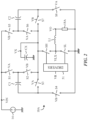
- FIG. 2 shows a particular implementation of the power converter architecture in FIG. 1 ;
- FIG. 3 shows a controller coupled to the power converter in FIG. 2 ;
- FIG. 4 shows a particular implementation of the controller in FIG. 3 ;
- FIG. 5 shows a timing diagram of relevant signals from the embodiment in FIG. 4 .
- FIG. 6 shows a close-up of selected signals in FIG. 5 ;
- FIG. 7 shows a DC model of a switched capacitor element
- FIGS. 8 A- 8 B show the relationship between the load current and the intermediate voltage ripple
- FIG. 9 shows a controller that synchronizes a regulating circuit that precedes a switched capacitor element
- FIG. 10 shows a three-phase controller that synchronizes a three-phase switched capacitor element that precedes a three-phase regulating circuit
- FIG. 11 shows a particular implementation of the three-phase controller in FIG. 10 ;
- FIGS. 12 A- 12 B show timing diagrams of relevant signals from the embodiment in FIG. 11 .
- the apparatus described herein provides a way to control the switched capacitor element 12 A and the regulating circuit 16 A in a modular multi-stage power converter architecture.
- controllers for power converters that utilize capacitors to transfer energy
- references are sometimes made herein to specific controllers for power converters that utilize capacitors to transfer energy. It should be understood that such references are merely exemplary and should not be construed as limiting. After reading the description provided herein, one of ordinary skill in the art will understand how to apply the concepts described herein to provide specific controllers for power converters that utilize capacitors to transfer energy.
- FIG. 2 illustrates a power converter 10 A that receives an input voltage VIN from the voltage source 14 and produces an output voltage VO that is lower than the input voltage VIN.
- the power converter 10 A is a particular embodiment of the power converter architecture illustrated in FIG. 1 .
- the switched capacitor element 12 A features a 2:1 dual-phase series-parallel switched capacitor network that includes power switches S 1 -S 8 and pump capacitors C 1 -C 2 .
- the regulating circuit 16 A features a buck converter that includes a low-side switch SL, a high-side switch SH, a filter inductor L 1 , and a driver stage 51 .
- the power switches S 1 , S 3 , S 6 , S 8 and the power switches S 2 , S 4 , S 5 , S 7 are always in complementary states.
- the power switches S 1 , S 3 , S 6 , S 8 are open and the power switches S 2 , S 4 , S 5 , S 7 are closed.
- the power switches S 1 , S 3 , S 6 , S 8 are closed and the power switches S 2 , S 4 , S 5 , S 7 are open.
- the switched capacitor element 12 A cycles through the first network state and the second network state, resulting in an intermediate voltage VX that is one-half of the input voltage VIN.
- the switched capacitor element 12 A is in the first network state when a first phase voltage VA is low and a second phase voltage VB is high. In contrast, the switched capacitor element 12 A is in the second network state when the first phase voltage VA is high and the second phase voltage VB is low.
- the two phase voltages VA, VB are non-overlapping and have approximately a fifty percent duty cycle.
- the low-side switch SL and the high-side switch SH chop the intermediate voltage VX into a switching voltage VLX.
- a LC filter receives the switching voltage VLX and generates the output voltage VO that is equal to the average of the switching voltage VLX.
- a regulation control voltage VR controls the duty cycle of the low-side switch SL and the high-side switch SH.
- the driver stage 51 provides the energy to open and close the low-side and high-side switches SL, SH.
- dead-time interval DT between the first network state and the second network state of the switched capacitor element 12 A.
- all of the switches in the switched capacitor element 12 A are open. This ensures a clean transition between the first network state and the second network state of the switched capacitor element 12 A, and vice versa. If the regulating circuit 16 A tries to draw current during the dead-time interval DT, a voltage ‘glitch’ will occur at the node between the switched capacitor element 12 A and the regulating circuit 16 A.
- the voltage ‘glitch’ can be reduced through the use of a glitch capacitor CX.
- a portion of the energy stored on the glitch capacitor CX is thrown away each time the switched capacitor element 12 A transitions between the first network state and the second network state, and vice versa.
- the energy loss is a result of the glitch capacitor CX being shorted to capacitors at a different voltage, such as pump capacitors C 1 , C 2 . Therefore, the use of a glitch capacitor CX to supply energy during the dead-time interval DT is an effective solution, but requires one additional capacitor and reduces the efficiency of the power converter 10 A.
- Embodiments described herein rely at least in part on the recognition that by synchronizing the switched capacitor element 12 A and the regulating circuit 16 A, the intermediate voltage VX ripple effect on the output voltage VO and the voltage “glitch” can be minimized.
- FIG. 3 illustrates a first generic controller 20 that synchronizes the switched capacitor element 12 A and the regulating circuit 16 A within the power converter 10 A shown in FIG. 2 .
- the first generic controller 20 receives five input signals and provides three output signals.
- the input signals include the input voltage VIN, the output voltage VO, the intermediate voltage VX, a reference voltage VREF, and a clock voltage VCLK.
- the output signals include the regulation control voltage VR, the first phase voltage VA, and the second phase voltage VB.
- the clock voltage VCLK sets the period of the regulation control voltage VR and the reference voltage VREF sets the desired output voltage VO.
- Synchronizing the switched capacitor element 12 A with the regulating circuit 16 A causes the intermediate voltage VX ripple to be in phase with the switching voltage VLX.
- feed-forward control is effective if the frequency of the regulating circuit 16 A is greater than or equal to the frequency of the switched capacitor element 12 A, thereby relieving the severe frequency constraint of separately controlled stages.
- the glitch capacitor CX shown in FIG. 2 , can be removed altogether if the dead-time interval DT of the switch capacitor element 12 A occurs when the regulating circuit 16 A is not drawing input current. Synchronizing the switched capacitor element 12 A and the regulating circuit 16 A ensures the proper timing between the dead-time interval DT and the interval during which the regulating circuit 16 A is not drawing input current.
- One more benefit of synchronizing the switched capacitor element 12 A and the regulating circuit 16 A is the ability to open and close the power switches S 1 -S 8 in the switched capacitor element 12 A when zero-current is flowing through the power switches S 1 -S 8 .
- This technique is often referred to as zero-current switching.
- the dead-time interval DT must occur when the regulating circuit 16 A is not drawing input current.
- FIG. 4 illustrates a controller 20 A that is a preferred embodiment of the first generic controller 20 .
- the controller 20 A can be separated into a first control section and a second control section.
- the control circuitry for the regulating circuit 16 A is in the first control section and includes first, second, third, and fourth control blocks 30 , 31 , 32 , 33 .
- the control circuitry for the switched capacitor element 12 A is in the second control section and includes fifth, sixth, and seventh control blocks 34 , 35 , 36 .
- the “link” between the fourth control block 33 and the fifth control block 34 enables synchronization of the first and second control sections.
- FIG. 5 illustrates some relevant signals generated by the controller 20 A.
- the relevant signals include the clock voltage VCLK, a saw-tooth voltage VSAW, the regulation control voltage VR, the switching voltage VLX, a filter inductor current IL, the intermediate voltage VX, the first phase voltage VA, and the second phase voltage VB.
- FIG. 6 illustrates a close-up of some of the waveforms in FIG. 5 , where the regulation control voltage period TSW is the inverse of the regulation control voltage VR frequency.
- the first control section within the controller 20 A uses a linear voltage-mode control scheme to control the regulating circuit 16 A.
- the controller 20 A compares the output voltage VO with the reference voltage VREF, thereby producing a residual voltage that is conditioned by the second control block 31 .
- a resulting error voltage VERR is then fed into the third control block 32 where it is compared with the saw-tooth voltage VSAW.
- the output of the third control block 32 is further conditioned by the fourth control block 33 , resulting in the regulation control voltage VR.
- the first control block 30 sets the frequency of the regulation control voltage VR by generating the saw-tooth voltage VSAW from the clock voltage VCLK. Additionally, the first control block 30 provides feed-forward control of the regulating circuit 16 A by adjusting the peak voltage of the saw-tooth voltage VSAW based upon the intermediate voltage VX. Alternatively, feed-forward control can be implemented by adjusting the error voltage VERR with respect to the input voltage VIN or the intermediate voltage VX in the second control block 31 .
- the second control section within the controller 20 A uses a hysteretic control scheme to control the switched capacitor element 12 A.
- the controller 20 A causes the first and second phase voltages VA, VB to cycle the switched capacitor element 12 A back and forth between the first network state and the second network state based upon a hysteresis band.
- the sixth control block 35 continuously compares the intermediate voltage VX with a trigger voltage VXL.
- the fifth control block 34 is triggered and then waits for a confirmation signal.
- the fourth control block 33 sends a signal informing the fifth control block 34 that it is acceptable to make a state change
- the dead-time interval DT shown in FIG. 6 .
- the first and second phase voltages VA, VB are set low.
- the fifth control block 34 is reset and the sequence repeats.
- the controller 20 A thus forces the frequency of the switched capacitor element 12 A to be submultiples of the frequency of the regulating circuit 16 A.
- This constraint is illustrated in FIG. 5 , where the frequencies of the first phase voltage VA and the second phase voltage VB are much lower than the frequency of the regulation control voltage VR. In some practices, the frequency of the second phase voltage VB is as little as a tenth that of the control voltage VR.
- the voltage ripple on the intermediate voltage VX is a piecewise linear approximation of a saw-tooth waveform.
- an intermediate peak-peak voltage ripple AVX is equal to the maximum intermediate voltage minus the minimum intermediate voltage under steady state conditions.
- the intermediate voltage VX comprises a high frequency component from the regulating circuit 16 A superimposed on the lower frequency saw-tooth waveform from the switched capacitor element 12 A.
- the intermediate voltage VX drops a delta voltage AVD below the trigger voltage VXL, as shown by the intermediate voltage VX curve in FIG. 5 .
- the delta voltage AVD is small, especially if the frequency of the switched capacitor element 12 A is much lower than the frequency of the regulating circuit 16 A.
- the delta voltage AVD at most can be equal to one-half of the intermediate peak-peak voltage ripple AVX and this occurs when the frequency of the switched capacitor element 12 A is equal to the frequency of the regulating circuit 16 A.
- FIG. 7 illustrates a DC model of the switched capacitor element 12 A coupled between the voltage source 14 and the regulating circuit 16 A.
- the DC model includes a transformer with a finite output resistance RO. Assuming the switched capacitor element 12 A delivers an intermediate current IX, the average of the intermediate voltage VX can be calculated using
- VX _ VIN ⁇ N ⁇ 2 N ⁇ 1 - IX ⁇ RO
- the configuration of the switches and capacitors in the switched capacitor element 12 A sets a voltage transformation ratio N 1 :N 2 . Meanwhile, the output resistance RO of the switched capacitor element 12 A accounts for the energy loss in charging/discharging the pump capacitors.
- VX VXL ⁇ VD+ ⁇ VX/ 2
- ⁇ ⁇ VX 2 [ VIN ⁇ N ⁇ 2 N ⁇ 1 - IX ⁇ RO - VXL + ⁇ ⁇ VD ] .
- the intermediate peak-peak voltage ripple ⁇ VX is function of operating parameters such as the intermediate current IX and the input voltage VIN. Additionally, due to the synchronization constraint, the intermediate peak-peak voltage ripple ⁇ VX is also a function of the delta voltage ⁇ VD.
- the trigger voltage VXL shown in FIG. 4 , can be adjusted on the fly.
- the seventh control block 36 utilizes the input voltage VIN and the intermediate voltage VX to make a decision on the appropriate value of the trigger voltage VXL. Therefore, when the input voltage VIN rises, the trigger voltage VXL rises in step.
- the dead-time interval DT sets the maximum duty cycle DMAX. It is often desirable to minimize the dead-time interval DT, thereby widening the duty cycle range of the regulating circuit 16 A.
- FIG. 8 A illustrates the period of the switched capacitor element 12 A and the intermediate peak-peak voltage ripple ⁇ VX as a function of the output current.
- the slope of the voltage ripple on the intermediate voltage VX decreases. This reduces the frequency of the first and second phase voltages VA, VB. Due to synchronization, the reduction in frequency occurs abruptly and only at specific output current values.
- the change in frequency takes place whenever the intermediate peak-peak voltage ripple ⁇ VX is equal to a maximum peak-peak voltage ripple ⁇ VMAX divided by two. Consequently, the intermediate peak-peak voltage ripple ⁇ VX follows a saw-tooth waveform with a fixed valley voltage.
- the intermediate peak-peak voltage ripple ⁇ VX approaches one-half of the maximum peak-peak voltage ripple ⁇ VMAX.
- the controller 20 A With a few modifications to the controller 20 A, it is also possible to get the intermediate peak-peak voltage ripple ⁇ VX to follow a saw-tooth waveform with a fixed peak voltage as illustrated in FIG. 8 B .
- the intermediate peak-peak voltage ripple ⁇ VX approaches the maximum peak-peak voltage ripple ⁇ VMAX.
- the main difference between the first approach in FIG. 8 A and second approach in FIG. 8 B is the distribution of frequencies and intermediate peak-peak voltage ripple ⁇ VX across the output current range.
- the controller 20 A depicted in FIG. 4 and described above is one of many possible implementations of the first generic controller 20 that can synchronize the power converter 10 A or any power converter that includes a switched capacitor element 12 A that precedes a regulating circuit 16 A.
- the switched capacitor element 12 A and the regulating circuit 16 A can be mixed and matched in a variety of different ways.
- FIG. 9 illustrates an alternative power converter 10 B, wherein a regulating circuit 16 A precedes a switched capacitor element 12 A.
- a second generic controller 21 synchronizes the regulating circuit 16 A and the switched capacitor element 12 A.
- the input and output signals of the second generic controller 21 are the same as that of the first generic controller 20 .
- the regulating circuit 16 A may include various types of switch-mode power converters, such as a boost converter, a resonant converter, and a fly-back converter.
- the switched capacitor element 12 A may include various types of switched capacitor converters, such as a series-parallel charge pump, a voltage doubler, and a cascade multiplier. Regardless of the selection of either the regulating circuit 16 A or the switched capacitor element 12 A, if the two stages are synchronized, the frequency of the switched capacitor element 12 A will change in discrete steps as the output current of the power converter 10 B is varied.
- FIG. 10 illustrates a three-phase power converter 10 C and a generic three phase-controller 22 that synchronizes the various stages.
- the three-phase power converter 10 C includes three regulating sub-elements: a first regulating circuit 16 A, a second regulating circuit 16 B, a third regulating circuit 16 C and three voltage transformation sub-elements: a first switched capacitor element 12 A, a second switched capacitor element 12 B, and a third switched capacitor element 12 C.
- the first, second, and third switched capacitor elements 12 A, 12 B, 12 C provide first, second, and third intermediate voltages VX 1 , VX 2 , VX 3 , respectively.
- First, second, and third regulation control voltages VR 1 , VR 2 , VR 3 control the first, second, and third regulating circuits 16 A, 16 B, 16 C, respectively. Furthermore, first and second phase voltages VA 1 , VB 1 control the first switched capacitor element 12 A; third and fourth phase voltages VA 2 , VB 2 control the second switched capacitor element 12 B; and fifth and sixth phase voltages VA 3 , VB 3 control the third switched capacitor element 12 C. Additionally, a regulation control bus BVR includes the first, second, and third regulation control voltages VR 1 , VR 2 , VR 3 . A first phase bus BVA includes the first, third, and fifth phase voltages VA 1 , VA 2 , VA 3 . Lastly, a second phase bus BVB includes the second, fourth, and sixth phase voltages VB 1 , VB 2 , VB 3 .
- FIG. 11 illustrates a three-phase controller 22 A that is a preferred embodiment of the generic three-phase controller 22 .
- the three-phase controller 22 A can be separated into a first control section and a second control section.
- the control circuitry for the first, second, and third regulating circuits 16 A, 16 B, 16 C is in the first control section and includes first, second, third, fourth, fifth, and sixth control blocks 30 , 31 , 32 A, 32 B, 32 C, 33 .
- the control circuitry for the first, second, and third switched capacitor elements 12 A, 12 B, 12 C is in the second control section and includes seventh, eighth, ninth, tenth, and eleventh control blocks 34 , 35 A, 35 B, 35 C, 36 .
- the three-phase controller 22 A looks very similar to the controller 20 A in FIG. 4 , but with additional input and output signals.
- a linear voltage-mode control scheme is used to control the regulating circuits 16 A- 16 C and a hysteretic control scheme is used to control the switched capacitor elements 12 A- 12 C. Consequently, the operation of the first and second control sections in the three-phase controller 22 A is similar to that described in connection with FIG. 4 .
- the first control block 30 sets the frequency and phase of the first, second, and third regulation control voltages VR 1 , VR 2 , VR 3 .
- the first control block 30 generates first, second, and third saw-tooth voltages VSAW 1 , VSAW 2 , VSAW 3 that are compared to an error voltage VERR by the third, fourth, and fifth control blocks 32 A, 32 B, 32 C, respectively.
- the resulting three outputs are further conditioned by the sixth control block 33 that produces the regulation control bus BVR.
- the first, second, and third intermediate voltages VX 1 , VX 2 , VX 3 are compared to a trigger voltage VXL produced by the eleventh control block 36 .
- the output of the eighth, ninth, tenth control blocks 35 A, 35 B, 35 C are further conditioned by the seventh control block 34 resulting in the first and second phase buses BVA, BVB.
- the ‘link’ between the sixth control block 33 and the seventh control block 34 enables synchronization of the first and second control sections.
- FIG. 12 A illustrates some relevant signals generated by the three-phase controller 22 A.
- the first, second, and third regulation control voltages VR 1 , VR 2 , VR 3 are one hundred and twenty degrees out of phase with each other.
- the phase voltages VA 1 , VA 2 , VA 3 are shifted in time with respect to each other the same amount as their corresponding regulation control voltages VR 1 , VR 2 , VR 3 are shifted in time with respect to each other.
- the second, fourth, and sixth phase voltages VB 1 , VB 2 , VB 3 are one hundred and eighty degrees out of phase with the first, third, and fifth phase voltages VA 1 , VA 2 , VA 3 , respectively.
- the frequency of the first, second, and third regulating circuits 16 A, 16 B, 16 C is one megahertz
- the rising and/or falling edges of the first, second, and third regulation control voltages VR 1 , VR 2 , VR 3 are separated by one-third of a microsecond. Consequently, the rising and/or falling edges of the first, third, and fifth phase voltages VA 1 , VA 2 , VA 3 are separated by one-third of a microsecond and the rising and/or falling edges of the second, fourth, and sixth phase voltages VB 1 , VB 2 , VB 3 are separated by one-third of a microsecond.
- the frequency of each of the regulating circuits 16 A- 16 C is one megahertz
- the period of each of the regulating circuits 16 A- 16 C is one microsecond.
- the rising and/or falling edges of the first, third, and fifth phase voltages VA 1 , VA 2 , VA 3 are separated by one and one-third of a microsecond and the rising and/or falling edges of the second, fourth, and sixth phase voltages VB 1 , VB 2 , VB 3 are separated by one and one-third of a microsecond.
- the more uniform spacing of the first intermediate voltage VX 1 ripple, the second intermediate voltage VX 2 ripple, and the third intermediate voltage VX 3 ripple reduces their effect on the output voltage VO.
- the glitch capacitor CX can be removed altogether if the dead-time interval DT of each of the switched capacitor elements 12 A, 12 B, 12 C occurs when their corresponding regulating circuits 16 A, 16 B, 16 C are neither sinking nor sourcing current through an inductive element.
- the filter inductor in a buck converter, the filter inductor is sinking current from the input only a portion of the time, whereas, in a boost converter, the filter inductor is sourcing current to the output only a portion of the time.
- These power converters have a discontinuous current interval during which current is either sunk or sourced. Therefore, the glitch capacitor CX is unnecessary if the dead-time interval DT of each of the switched capacitor elements 12 A, 12 B, 12 C occurs during the discontinuous input current interval.
- Both the controller 20 A in FIG. 4 and the three-phase controller 22 A in FIG. 11 utilize linear voltage-mode control.
- other control techniques such as non-linear voltage-mode control, peak current-mode control, and average current-mode control are applicable as well.
- control circuitry described herein synchronizes the switched capacitor elements 12 A with the regulating circuits 16 A in the modular multi-stage power converter architecture.
- control circuitry described herein provides a way to minimize the effect of the intermediate voltage VX ripple on the output voltage VO and minimize the production of a voltage ‘glitch’ during the dead-time internal DT of the switched capacitor element 12 A.
Landscapes
- Engineering & Computer Science (AREA)
- Power Engineering (AREA)
- Physics & Mathematics (AREA)
- Electromagnetism (AREA)
- General Physics & Mathematics (AREA)
- Radar, Positioning & Navigation (AREA)
- Automation & Control Theory (AREA)
- Dc-Dc Converters (AREA)
- Power Conversion In General (AREA)
Abstract
Description
The configuration of the switches and capacitors in the switched
As illustrated by the equation above, the dead-time interval DT sets the maximum duty cycle DMAX. It is often desirable to minimize the dead-time interval DT, thereby widening the duty cycle range of the regulating
Claims (30)
Priority Applications (1)
| Application Number | Priority Date | Filing Date | Title |
|---|---|---|---|
| US18/743,046 US12176815B2 (en) | 2011-12-19 | 2024-06-13 | Switched-capacitor circuit control in power converters |
Applications Claiming Priority (8)
| Application Number | Priority Date | Filing Date | Title |
|---|---|---|---|
| US201161577271P | 2011-12-19 | 2011-12-19 | |
| PCT/US2012/070555 WO2013096416A1 (en) | 2011-12-19 | 2012-12-19 | Control of power converters with capacitive energy transfer |
| US14/309,003 US9143037B2 (en) | 2011-12-19 | 2014-06-19 | Control of multi-phase power coverters with capacitive energy transfer |
| US14/857,141 US10686380B2 (en) | 2011-12-19 | 2015-09-17 | Switched-capacitor circuit control in power converters |
| US16/872,207 US11165350B2 (en) | 2011-12-19 | 2020-05-11 | Switched-capacitor circuit control in power converters |
| US17/491,983 US11936300B2 (en) | 2011-12-19 | 2021-10-01 | Switched-capacitor circuit control in power converters |
| US18/606,319 US20240305201A1 (en) | 2011-12-19 | 2024-03-15 | Switched-capacitor circuit control in power converters |
| US18/743,046 US12176815B2 (en) | 2011-12-19 | 2024-06-13 | Switched-capacitor circuit control in power converters |
Related Parent Applications (1)
| Application Number | Title | Priority Date | Filing Date |
|---|---|---|---|
| US18/606,319 Continuation US20240305201A1 (en) | 2011-12-19 | 2024-03-15 | Switched-capacitor circuit control in power converters |
Publications (2)
| Publication Number | Publication Date |
|---|---|
| US20240339932A1 US20240339932A1 (en) | 2024-10-10 |
| US12176815B2 true US12176815B2 (en) | 2024-12-24 |
Family
ID=48609475
Family Applications (7)
| Application Number | Title | Priority Date | Filing Date |
|---|---|---|---|
| US13/718,658 Active US8723491B2 (en) | 2011-12-19 | 2012-12-18 | Control of power converters with capacitive energy transfer |
| US14/309,003 Active US9143037B2 (en) | 2011-12-19 | 2014-06-19 | Control of multi-phase power coverters with capacitive energy transfer |
| US14/857,141 Active US10686380B2 (en) | 2011-12-19 | 2015-09-17 | Switched-capacitor circuit control in power converters |
| US16/872,207 Active US11165350B2 (en) | 2011-12-19 | 2020-05-11 | Switched-capacitor circuit control in power converters |
| US17/491,983 Active 2033-04-09 US11936300B2 (en) | 2011-12-19 | 2021-10-01 | Switched-capacitor circuit control in power converters |
| US18/606,319 Pending US20240305201A1 (en) | 2011-12-19 | 2024-03-15 | Switched-capacitor circuit control in power converters |
| US18/743,046 Active US12176815B2 (en) | 2011-12-19 | 2024-06-13 | Switched-capacitor circuit control in power converters |
Family Applications Before (6)
| Application Number | Title | Priority Date | Filing Date |
|---|---|---|---|
| US13/718,658 Active US8723491B2 (en) | 2011-12-19 | 2012-12-18 | Control of power converters with capacitive energy transfer |
| US14/309,003 Active US9143037B2 (en) | 2011-12-19 | 2014-06-19 | Control of multi-phase power coverters with capacitive energy transfer |
| US14/857,141 Active US10686380B2 (en) | 2011-12-19 | 2015-09-17 | Switched-capacitor circuit control in power converters |
| US16/872,207 Active US11165350B2 (en) | 2011-12-19 | 2020-05-11 | Switched-capacitor circuit control in power converters |
| US17/491,983 Active 2033-04-09 US11936300B2 (en) | 2011-12-19 | 2021-10-01 | Switched-capacitor circuit control in power converters |
| US18/606,319 Pending US20240305201A1 (en) | 2011-12-19 | 2024-03-15 | Switched-capacitor circuit control in power converters |
Country Status (6)
| Country | Link |
|---|---|
| US (7) | US8723491B2 (en) |
| KR (1) | KR20140103351A (en) |
| CN (2) | CN110277908B (en) |
| DE (1) | DE112012005353T5 (en) |
| GB (1) | GB2512259A (en) |
| WO (1) | WO2013096416A1 (en) |
Families Citing this family (48)
| Publication number | Priority date | Publication date | Assignee | Title |
|---|---|---|---|---|
| US8212541B2 (en) | 2008-05-08 | 2012-07-03 | Massachusetts Institute Of Technology | Power converter with capacitive energy transfer and fast dynamic response |
| US10389235B2 (en) | 2011-05-05 | 2019-08-20 | Psemi Corporation | Power converter |
| WO2012151466A2 (en) | 2011-05-05 | 2012-11-08 | Arctic Sand Technologies, Inc. | Dc-dc converter with modular stages |
| US9882471B2 (en) | 2011-05-05 | 2018-01-30 | Peregrine Semiconductor Corporation | DC-DC converter with modular stages |
| US10680515B2 (en) | 2011-05-05 | 2020-06-09 | Psemi Corporation | Power converters with modular stages |
| US8743553B2 (en) | 2011-10-18 | 2014-06-03 | Arctic Sand Technologies, Inc. | Power converters with integrated capacitors |
| US8723491B2 (en) | 2011-12-19 | 2014-05-13 | Arctic Sand Technologies, Inc. | Control of power converters with capacitive energy transfer |
| US9583948B2 (en) * | 2012-10-26 | 2017-02-28 | Analog Devices, Inc. | Isolated digital transmission with improved EMI immunity |
| US8693224B1 (en) | 2012-11-26 | 2014-04-08 | Arctic Sand Technologies Inc. | Pump capacitor configuration for switched capacitor circuits |
| US8724353B1 (en) | 2013-03-15 | 2014-05-13 | Arctic Sand Technologies, Inc. | Efficient gate drivers for switched capacitor converters |
| US8619445B1 (en) | 2013-03-15 | 2013-12-31 | Arctic Sand Technologies, Inc. | Protection of switched capacitor power converter |
| US9203299B2 (en) | 2013-03-15 | 2015-12-01 | Artic Sand Technologies, Inc. | Controller-driven reconfiguration of switched-capacitor power converter |
| US9847712B2 (en) | 2013-03-15 | 2017-12-19 | Peregrine Semiconductor Corporation | Fault control for switched capacitor power converter |
| US9660520B2 (en) | 2013-04-09 | 2017-05-23 | Massachusetts Institute Of Technology | Method and apparatus to provide power conversion with high power factor |
| US9041459B2 (en) | 2013-09-16 | 2015-05-26 | Arctic Sand Technologies, Inc. | Partial adiabatic conversion |
| US9742266B2 (en) * | 2013-09-16 | 2017-08-22 | Arctic Sand Technologies, Inc. | Charge pump timing control |
| US9601998B2 (en) | 2013-10-07 | 2017-03-21 | Lion Semiconductor Inc. | Hybrid regulator including a buck converter and a switched capacitor converter |
| US9825545B2 (en) | 2013-10-29 | 2017-11-21 | Massachusetts Institute Of Technology | Switched-capacitor split drive transformer power conversion circuit |
| GB2538665B (en) | 2014-03-14 | 2021-11-10 | Arctic Sand Technologies Inc | Charge pump stability control |
| US10128745B2 (en) | 2014-03-14 | 2018-11-13 | Psemi Corporation | Charge balanced charge pump control |
| US10693368B2 (en) | 2014-03-14 | 2020-06-23 | Psemi Corporation | Charge pump stability control |
| WO2016004427A1 (en) | 2014-07-03 | 2016-01-07 | Massachusetts Institute Of Technology | High-frequency, high-density power factor correction conversion for universal input grid interface |
| WO2016149063A1 (en) | 2015-03-13 | 2016-09-22 | Arctic Sand Technologies, Inc. | Dc-dc transformer with inductor for the facilitation of adiabatic inter-capacitor charge transport |
| WO2017007991A1 (en) * | 2015-07-08 | 2017-01-12 | Arctic Sand Technologies, Inc. | Switched-capacitor power converters |
| US11258371B2 (en) * | 2016-02-16 | 2022-02-22 | Psemi Corporation | Switched capacitors for AC-DC applications |
| CN109075703A (en) | 2016-03-11 | 2018-12-21 | 派赛公司 | Battery management system with adiabatic switched capacitor circuit |
| WO2017160821A1 (en) * | 2016-03-14 | 2017-09-21 | Arctic Sand Technologies, Inc. | Slew-controlled switched capacitors for ac-dc applications |
| WO2017195592A1 (en) * | 2016-05-10 | 2017-11-16 | 株式会社村田製作所 | Power converter unit |
| JP6521187B2 (en) * | 2016-10-06 | 2019-05-29 | 株式会社村田製作所 | DC-DC converter |
| KR101976789B1 (en) * | 2017-04-25 | 2019-05-09 | 한국과학기술원 | Boost Converter having high voltage ratio and control method thereof |
| US10224803B1 (en) * | 2017-12-20 | 2019-03-05 | Infineon Technologies Austria Ag | Switched capacitor converter with compensation inductor |
| US10193448B1 (en) | 2018-03-26 | 2019-01-29 | Semiconductor Components Industries, Llc | Method of forming a power supply control circuit and structure therefor |
| US10790741B2 (en) | 2018-09-24 | 2020-09-29 | Psemi Corporation | Pole compensation in reconfigurable power converter |
| CN109587774B (en) * | 2018-10-25 | 2020-09-11 | 华为技术有限公司 | A method, control device and communication equipment for energy efficiency control |
| TWI682614B (en) * | 2018-10-26 | 2020-01-11 | 緯穎科技服務股份有限公司 | Multi-phase power supply for stepdown system |
| TWI679514B (en) * | 2018-12-04 | 2019-12-11 | 新唐科技股份有限公司 | Power converter |
| TWI689161B (en) | 2018-12-22 | 2020-03-21 | 新唐科技股份有限公司 | Power converter |
| US10686367B1 (en) | 2019-03-04 | 2020-06-16 | Psemi Corporation | Apparatus and method for efficient shutdown of adiabatic charge pumps |
| US10734893B1 (en) | 2019-05-03 | 2020-08-04 | Psemi Corporation | Driving circuit for switches used in a charge pump |
| US11422617B2 (en) * | 2019-09-03 | 2022-08-23 | Dell Products L.P. | Systems and methods for providing peak current assistance to a voltage regulator using a switched capacitor converter |
| US10924006B1 (en) | 2019-09-30 | 2021-02-16 | Psemi Corporation | Suppression of rebalancing currents in a switched-capacitor network |
| US11764669B2 (en) | 2020-09-30 | 2023-09-19 | The Trustees Of Princeton University | Power converter |
| US11532986B2 (en) * | 2020-10-14 | 2022-12-20 | Infineon Technologies Austria Ag | Multi-stage power converter with transformless switched-capacitor converter and control |
| US11855536B2 (en) | 2021-09-23 | 2023-12-26 | Psemi Corporation | Power converters, power systems, and switch topologies |
| JP2024005754A (en) * | 2022-06-30 | 2024-01-17 | ローム株式会社 | Series capacitor buck converter and its controller circuit and control method |
| JP2024024526A (en) * | 2022-08-09 | 2024-02-22 | ローム株式会社 | Series capacitor buck converter and its controller circuit and control method |
| WO2024151345A1 (en) * | 2023-01-11 | 2024-07-18 | Cirrus Logic International Semiconductor Ltd. | Power converter system with cascaded power stages and sharing of information between power stages for control |
| US12451804B2 (en) * | 2023-04-27 | 2025-10-21 | Cirrus Logic Inc. | Power converter system |
Citations (456)
| Publication number | Priority date | Publication date | Assignee | Title |
|---|---|---|---|---|
| US3370215A (en) | 1966-02-09 | 1968-02-20 | Basic Inc | Step up cycloconverter with harmonic distortion reducing means |
| US3745437A (en) | 1972-05-18 | 1973-07-10 | Lorain Prod Corp | Regulator circuit having a multi-stepped regulating wave |
| US3818360A (en) | 1972-06-23 | 1974-06-18 | Telecommunications Sa | Regenerative repeater output stage for bipolar coded message signals |
| US3818306A (en) | 1972-02-18 | 1974-06-18 | Sits Soc It Telecom Siemens | Stabilized power supply with transformer isolation |
| JPS5297116U (en) | 1976-01-14 | 1977-07-21 | ||
| US4214174A (en) | 1977-03-25 | 1980-07-22 | Plessey Handel Und Investments Ag | Voltage multiplier employing clock gated transistor chain |
| US4408268A (en) | 1982-08-09 | 1983-10-04 | General Electric Company | Pulse modulated electronic voltage controller with smooth voltage output |
| US4415959A (en) | 1981-03-20 | 1983-11-15 | Vicor Corporation | Forward converter switching at zero current |
| US4513364A (en) | 1980-08-14 | 1985-04-23 | Nilssen Ole K | Thermally controllable variable frequency inverter |
| US4812961A (en) | 1987-05-15 | 1989-03-14 | Linear Technology, Inc. | Charge pump circuitry having low saturation voltage and current-limited switch |
| US4903181A (en) | 1989-05-16 | 1990-02-20 | American Telephone And Telegraph Company, At&T Bell Laboratories | Power converter having parallel power switching systems coupled by an impedance inversion network |
| US5006782A (en) | 1989-06-15 | 1991-04-09 | International Rectifier Corporation | Cascaded buck converter circuit with reduced power loss |
| US5057986A (en) | 1990-03-12 | 1991-10-15 | Unisys Corporation | Zero-voltage resonant transition switching power converter |
| US5119283A (en) | 1991-06-10 | 1992-06-02 | General Electric Company | High power factor, voltage-doubler rectifier |
| US5132606A (en) | 1991-01-07 | 1992-07-21 | Edward Herbert | Method and apparatus for controlling the input impedance of a power converter |
| US5159539A (en) | 1989-08-17 | 1992-10-27 | Mitsubishi Denki Kabushiki Kaisha | High frequency DC/AC power converting apparatus |
| EP0513920A2 (en) | 1991-05-15 | 1992-11-19 | Matsushita Electric Works, Ltd. | Apparatus for operating discharge lamps |
| US5198970A (en) | 1988-04-27 | 1993-03-30 | Mitsubishi Denki Kabushiki Kaisha | A.C. power supply apparatus |
| US5268832A (en) | 1991-08-20 | 1993-12-07 | Kabushiki Kaisha Toshiba | DC/AC inverter controller for solar cell, including maximum power point tracking function |
| US5301097A (en) | 1992-06-10 | 1994-04-05 | Intel Corporation | Multi-staged charge-pump with staggered clock phases for providing high current capability |
| US5331303A (en) | 1992-04-21 | 1994-07-19 | Kabushiki Kaisha Toshiba | Power transformer for cycloconverters |
| US5345376A (en) | 1993-02-19 | 1994-09-06 | Tescom Corporation | Switching power supply with electronic isolation |
| US5402329A (en) | 1992-12-09 | 1995-03-28 | Ernest H. Wittenbreder, Jr. | Zero voltage switching pulse width modulated power converters |
| US5504418A (en) | 1993-11-26 | 1996-04-02 | Hughes Aircraft Company | Full shunt boost switching voltage limiter for solar panel array |
| US5548206A (en) | 1993-09-30 | 1996-08-20 | National Semiconductor Corporation | System and method for dual mode DC-DC power conversion |
| US5557193A (en) | 1992-10-12 | 1996-09-17 | Mitsubishi Denki Kabushiki Kaisha | Stabilized voltage generating circuit and internal voltage down converter and a method of generating an internal operating power supply voltage for a dynamically operating circuit |
| CN1132959A (en) | 1994-10-14 | 1996-10-09 | 松下电工株式会社 | Power converting system |
| EP0773622A2 (en) | 1995-11-08 | 1997-05-14 | Sony Corporation | Internal power supply circuit |
| US5661348A (en) | 1995-07-18 | 1997-08-26 | Dell Usa L.P. | Method and apparatus for passive input current waveform correction for universal offline switchmode power supply |
| US5717581A (en) | 1994-06-30 | 1998-02-10 | Sgs-Thomson Microelectronics, Inc. | Charge pump circuit with feedback control |
| US5737201A (en) | 1991-07-25 | 1998-04-07 | Centre Nat Rech Scient | Electronic device for electrical energy conversion between a voltage source and a current source by means of controllable switching cells |
| US5761058A (en) | 1995-07-26 | 1998-06-02 | Matsushita Electric Works, Ltd. | Power converter apparatus for a discharge lamp |
| US5793626A (en) | 1996-05-29 | 1998-08-11 | Lucent Technologies Inc. | High efficiency bimodal power converter and method of operation thereof |
| US5801987A (en) | 1997-03-17 | 1998-09-01 | Motorola, Inc. | Automatic transition charge pump for nonvolatile memories |
| US5812017A (en) | 1994-12-05 | 1998-09-22 | Sgs-Thomson Microelectronics, S.R.L. | Charge pump voltage multiplier circuit |
| US5831846A (en) | 1997-08-22 | 1998-11-03 | Lucent Technologies Inc. | Dual mode boost converter and method of operation thereof |
| JPH10327573A (en) | 1997-05-23 | 1998-12-08 | Fuji Electric Co Ltd | Semiconductor stack of power converter |
| US5892395A (en) | 1997-05-02 | 1999-04-06 | Motorola, Inc. | Method and apparatus for efficient signal power amplification |
| JPH11113249A (en) | 1997-10-03 | 1999-04-23 | Stanley Electric Co Ltd | Switched capacitor transformer |
| US5907484A (en) | 1996-04-25 | 1999-05-25 | Programmable Microelectronics Corp. | Charge pump |
| JPH11235053A (en) | 1998-02-10 | 1999-08-27 | Takaoka Electric Mfg Co Ltd | Stack for power converter |
| US5956243A (en) | 1998-08-12 | 1999-09-21 | Lucent Technologies, Inc. | Three-level boost rectifier with voltage doubling switch |
| US5959565A (en) | 1996-11-29 | 1999-09-28 | Rohm Co., Ltd. | Switched capacitor |
| US5959585A (en) | 1995-11-23 | 1999-09-28 | Robert Bosch Gmbh | Vehicle antenna arrangement and auxiliary vehicle antenna |
| US5978283A (en) | 1998-07-02 | 1999-11-02 | Aplus Flash Technology, Inc. | Charge pump circuits |
| US5982645A (en) | 1992-08-25 | 1999-11-09 | Square D Company | Power conversion and distribution system |
| JP2000134095A (en) | 1998-10-28 | 2000-05-12 | Murata Mfg Co Ltd | Pll module and portable terminal device |
| US6107864A (en) | 1998-08-24 | 2000-08-22 | Mitsubishi Denki Kabushiki Kaisha | Charge pump circuit |
| US6133788A (en) | 1998-04-02 | 2000-10-17 | Ericsson Inc. | Hybrid Chireix/Doherty amplifiers and methods |
| US6140807A (en) | 1998-10-01 | 2000-10-31 | Motorola, Inc. | Electronic device and associated method for charging an energy storage circuit with a DC-DC converter |
| US6154380A (en) | 1996-08-22 | 2000-11-28 | Telefonaktiebolaget Lm Ericsson | AC/DC boost converter |
| US6157253A (en) | 1999-09-03 | 2000-12-05 | Motorola, Inc. | High efficiency power amplifier circuit with wide dynamic backoff range |
| US6178102B1 (en) | 1998-09-16 | 2001-01-23 | Crown Audio, Inc. | Regulated DC output power supply for amplifiers |
| US6198645B1 (en) | 1998-07-02 | 2001-03-06 | National Semiconductor Corporation | Buck and boost switched capacitor gain stage with optional shared rest state |
| US6255906B1 (en) | 1999-09-30 | 2001-07-03 | Conexant Systems, Inc. | Power amplifier operated as an envelope digital to analog converter with digital pre-distortion |
| US6275018B1 (en) | 2000-06-02 | 2001-08-14 | Iwatt | Switching power converter with gated oscillator controller |
| US6316956B1 (en) | 1999-10-22 | 2001-11-13 | Motorola, Inc. | Multiple redundant reliability enhancement method for integrated circuits and transistors |
| US6327462B1 (en) | 1998-12-29 | 2001-12-04 | Conexant Systems, Inc. | System and method for dynamically varying operational parameters of an amplifier |
| US6339538B1 (en) | 1998-06-22 | 2002-01-15 | Clayton Kling Philips Handleman | Inverter circuit and method of operation |
| US20020008567A1 (en) * | 2000-06-13 | 2002-01-24 | Henry George C. | Multiple output charge pump |
| JP2002062858A (en) | 1995-01-11 | 2002-02-28 | Seiko Epson Corp | Power supply circuit, liquid crystal display device and electronic equipment |
| US6362608B1 (en) | 2001-02-01 | 2002-03-26 | Maxim Integrated Products, Inc. | Multi-phase switching converters and methods |
| US6377117B2 (en) | 1999-07-27 | 2002-04-23 | Conexant Systems, Inc. | Method and system for efficiently transmitting energy from an RF device |
| EP1199788A1 (en) | 2000-10-17 | 2002-04-24 | STMicroelectronics S.r.l. | Inductive DC-to-DC switching converter |
| US20020060914A1 (en) | 1999-03-23 | 2002-05-23 | Advanced Energy Industries, P.C. | High frequency power generator and related methods |
| US6396341B1 (en) | 2000-12-29 | 2002-05-28 | Ericsson Inc. | Class E Doherty amplifier topology for high efficiency signal transmitters |
| US6400579B2 (en) | 2000-03-24 | 2002-06-04 | Slobodan Cuk | Lossless switching DC to DC converter with DC transformer |
| US6411531B1 (en) | 2000-11-21 | 2002-06-25 | Linear Technology Corporation | Charge pump DC/DC converters with reduced input noise |
| US6429632B1 (en) | 2000-02-11 | 2002-08-06 | Micron Technology, Inc. | Efficient CMOS DC-DC converters based on switched capacitor power supplies with inductive current limiters |
| JP2002233139A (en) | 2001-02-05 | 2002-08-16 | Matsushita Electric Ind Co Ltd | DC-DC converter |
| US20020130704A1 (en) | 2001-02-01 | 2002-09-19 | Takao Myono | Charge pump circuit |
| US20020158660A1 (en) | 2001-03-09 | 2002-10-31 | Samsung Electronics Co., Ltd. | Hybrid power supply circuit and method for charging/discharging a logic circuit using the same |
| US6476666B1 (en) | 2001-05-30 | 2002-11-05 | Alliance Semiconductor Corporation | Bootstrapped charge pump |
| US6486728B2 (en) | 2001-03-16 | 2002-11-26 | Matrix Semiconductor, Inc. | Multi-stage charge pump |
| US6501325B1 (en) | 2001-01-18 | 2002-12-31 | Cypress Semiconductor Corp. | Low voltage supply higher efficiency cross-coupled high voltage charge pumps |
| US6504422B1 (en) | 2000-11-21 | 2003-01-07 | Semtech Corporation | Charge pump with current limiting circuit |
| US6507503B2 (en) | 2001-05-17 | 2003-01-14 | Abb Ab | Apparatus and a method for voltage conversion |
| US6512411B2 (en) | 1999-08-05 | 2003-01-28 | Maxim Integrated Products, Inc. | Charge pump mode transition control |
| US6515612B1 (en) | 2001-10-23 | 2003-02-04 | Agere Systems, Inc. | Method and system to reduce signal-dependent charge drawn from reference voltage in switched capacitor circuits |
| US6563235B1 (en) | 2000-10-03 | 2003-05-13 | National Semiconductor Corporation | Switched capacitor array circuit for use in DC-DC converter and method |
| US20030169096A1 (en) | 2000-09-15 | 2003-09-11 | Infineon Technologies North America Corp. | Method to improve charge pump reliability, efficiency and size |
| US6650552B2 (en) | 2001-05-25 | 2003-11-18 | Tdk Corporation | Switching power supply unit with series connected converter circuits |
| US6657876B2 (en) | 2001-07-09 | 2003-12-02 | Sharp Kabushiki Kaisha | Switched-capacitor-type stabilized power supply device |
| US6657875B1 (en) | 2002-07-16 | 2003-12-02 | Fairchild Semiconductor Corporation | Highly efficient step-down/step-up and step-up/step-down charge pump |
| US20030227280A1 (en) | 2002-01-31 | 2003-12-11 | Patrizio Vinciarelli | Factorized power architecture with point of load sine amplitude converters |
| US20040004851A1 (en) | 2002-04-18 | 2004-01-08 | Kohzoh Itoh | Charge pump circuit and power supply circuit |
| US6700803B2 (en) | 2001-08-14 | 2004-03-02 | The Board Of Trustees Of The University Of Illinois | Systems and methods for pulse width modulation |
| US20040041620A1 (en) | 2002-09-03 | 2004-03-04 | D'angelo Kevin P. | LED driver with increased efficiency |
| CN1483204A (en) | 2000-06-30 | 2004-03-17 | ض� | Inductive charge pump for supplying voltage to flash memory and other applications |
| US6738277B2 (en) | 2001-11-27 | 2004-05-18 | Power Integrations, Inc. | Method and apparatus for balancing active capacitor leakage current |
| US6738432B2 (en) | 2001-03-21 | 2004-05-18 | Ericsson Inc. | System and method for RF signal amplification |
| US6759766B2 (en) | 2001-12-18 | 2004-07-06 | Fuji Xerox Co., Ltd. | Power supply apparatus and image forming apparatus using the same |
| US20040170030A1 (en) | 2001-05-09 | 2004-09-02 | Thomas Duerbaum | Resonant converter |
| US6791298B2 (en) | 2001-11-05 | 2004-09-14 | Shakti Systems, Inc. | Monolithic battery charging device |
| FR2852748A1 (en) | 2003-03-18 | 2004-09-24 | Thales Sa | SYNCHRONOUS SWITCHING MACHINE WITH LOW LOSS |
| US6798177B1 (en) | 2002-10-15 | 2004-09-28 | Arques Technology, Inc. | Boost-buck cascade converter for pulsating loads |
| US20040222775A1 (en) | 2003-01-23 | 2004-11-11 | Yasunori Muramatsu | Charge pump type DC/DC converter |
| US20050007184A1 (en) | 2003-06-19 | 2005-01-13 | Seiko Epson Corporation | Booster circuit, semiconductor device, and display device |
| US20050024125A1 (en) | 2003-08-01 | 2005-02-03 | Mcnitt John L. | Highly efficient, high current drive, multi-phase voltage multiplier |
| US20050047181A1 (en) | 2003-08-29 | 2005-03-03 | Isao Yamamoto | Power supply apparatus |
| US20050067711A1 (en) | 2003-09-30 | 2005-03-31 | Opheim Tony A. | Providing a via with an increased via contact area |
| US20050088865A1 (en) | 2003-10-24 | 2005-04-28 | Alcatel | High power switching converter |
| US20050102798A1 (en) | 2003-10-22 | 2005-05-19 | Hideo Kato | Hinge for portable terminal |
| DE10358299A1 (en) | 2003-12-12 | 2005-07-14 | Infineon Technologies Ag | Capacitor component for integrated circuits has trench in a substrate containing alternating conductive and dielectric layers |
| US6927441B2 (en) | 2001-03-20 | 2005-08-09 | Stmicroelectronics S.R.L. | Variable stage charge pump |
| US6934167B2 (en) | 2003-05-01 | 2005-08-23 | Delta Electronics, Inc. | Contactless electrical energy transmission system having a primary side current feedback control and soft-switched secondary side rectifier |
| US20050207133A1 (en) | 2004-03-11 | 2005-09-22 | Mark Pavier | Embedded power management control circuit |
| US20050213280A1 (en) | 2004-03-25 | 2005-09-29 | Integral Wave Technologies, Inc. | Trench capacitor power supply system and method |
| US20050213267A1 (en) | 2004-03-25 | 2005-09-29 | Integral Wave Technologies, Inc. | Switched-capacitor power supply system and method |
| US20050219878A1 (en) | 2004-03-30 | 2005-10-06 | Tomoyuki Ito | Boost circuit capable of step-up ratio control |
| US20050254272A1 (en) | 2004-02-24 | 2005-11-17 | Patrizio Vinciarelli | Energy storage and hold-up method and apparatus for high density power conversion |
| US6980181B2 (en) | 2001-02-08 | 2005-12-27 | Seiko Instruments Inc. | LED drive circuit |
| US20050286278A1 (en) | 2004-04-22 | 2005-12-29 | Perreault David J | Method and apparatus for switched-mode power conversion at radio frequencies |
| JP2006025592A (en) | 2004-07-08 | 2006-01-26 | Analog Integrations Corp | Constant frequency operation type charge pump dc-dc converter |
| US6995995B2 (en) | 2003-12-03 | 2006-02-07 | Fairchild Semiconductor Corporation | Digital loop for regulating DC/DC converter with segmented switching |
| US7071660B2 (en) | 2004-02-20 | 2006-07-04 | Virginia Tech Intellectual Properties, Inc. | Two-stage voltage regulators with adjustable intermediate bus voltage, adjustable switching frequency, and adjustable number of active phases |
| US7072195B2 (en) | 2002-02-22 | 2006-07-04 | Xantrex Technology Inc. | Modular AC voltage supply and algorithm for controlling the same |
| US20060153495A1 (en) | 2004-12-06 | 2006-07-13 | John Wynne | Galvanically isolated signal conditioning system |
| US7091778B2 (en) | 2003-09-19 | 2006-08-15 | M/A-Com, Inc. | Adaptive wideband digital amplifier for linearly modulated signal amplification and transmission |
| US7103114B1 (en) | 1999-09-24 | 2006-09-05 | Centre National D'etude Spatiales (C.N.E.S.) | Modulated radio signal transmitter with self-adapted amplification polarization |
| US20060213890A1 (en) | 2005-03-24 | 2006-09-28 | Lincoln Global, Inc. | Three stage power source for electric ARC welding |
| US20060226130A1 (en) | 2005-04-08 | 2006-10-12 | Lincoln Global, Inc. | Chopper output stage for arc welder power source |
| US20060244513A1 (en) | 2005-04-28 | 2006-11-02 | Chih-Jen Yen | Charge pump |
| US7145382B2 (en) | 2004-01-02 | 2006-12-05 | National Chiao Tung University | Charge pump circuit suitable for low-voltage process |
| US7157956B2 (en) | 2004-12-03 | 2007-01-02 | Silicon Laboratories, Inc. | Switched capacitor input circuit and method therefor |
| US7161816B2 (en) | 2003-06-30 | 2007-01-09 | Iwatt Inc. | System and method for input current shaping in a power converter |
| US20070013448A1 (en) | 2005-07-14 | 2007-01-18 | Matsushita Electric Industrial Co., Ltd. | Charge pump circuit |
| US20070024346A1 (en) | 2005-07-28 | 2007-02-01 | Matsushita Electric Industrial Co., Ltd. | Charge pump circuit and semiconductor integrated circuit incorporating the same |
| EP1750366A2 (en) | 2005-07-29 | 2007-02-07 | Mks Instruments, Inc. | High reliability RF generator architecture |
| US7187159B2 (en) | 2003-04-14 | 2007-03-06 | Ricoh Company, Ltd. | DC—DC converter |
| US20070051712A1 (en) | 2004-07-13 | 2007-03-08 | Lincoln Global, Inc. | Three stage power source for electric arc welding |
| US20070066224A1 (en) | 2005-02-28 | 2007-03-22 | Sirit, Inc. | High efficiency RF amplifier and envelope modulator |
| US20070066250A1 (en) | 2005-09-22 | 2007-03-22 | Kyoichi Takahashi | Electronic parts for high frequency power amplifier and wireless communication device |
| US20070069818A1 (en) | 2004-10-28 | 2007-03-29 | Broadcom Corporation | Multilevel power amplifier architecture using multi-tap transformer |
| US20070085187A1 (en) | 2005-09-07 | 2007-04-19 | Alpha & Omega Semiconductor, Ltd | Vertically packaged MOSFET and IC power devices as integrated module using 3D interconnected laminates |
| US20070091655A1 (en) | 2005-09-06 | 2007-04-26 | Manabu Oyama | Switching power supply apparatus provided with series-connected charge pump circuits |
| US7224062B2 (en) | 2005-01-21 | 2007-05-29 | Via Technologies, Inc. | Chip package with embedded panel-shaped component |
| US20070123184A1 (en) | 2005-11-30 | 2007-05-31 | Kabushiki Kaisha Toshiba | Signal processor for use with a power amplifier in a wireless circuit |
| US7236542B2 (en) | 2002-09-17 | 2007-06-26 | Nokia Corporation | Multi-mode envelope restoration architecture for RF transmitters |
| CN1988349A (en) | 2005-12-21 | 2007-06-27 | 株式会社日立制作所 | Bi-directional DC-DC converter and control method |
| US20070146090A1 (en) | 2005-12-22 | 2007-06-28 | M/A-Com Eurotec Bv | Apparatus, system, and method for digital base modulation of power amplifier in polar transmitter |
| US20070146020A1 (en) | 2005-11-29 | 2007-06-28 | Advanced Analogic Technologies, Inc | High Frequency Power MESFET Gate Drive Circuits |
| US20070161266A1 (en) | 2004-09-29 | 2007-07-12 | Murata Manufacturing Co., Ltd. | Stacked module and manufacturing method thereof |
| US20070159257A1 (en) | 2003-03-04 | 2007-07-12 | Lee Dong-Geun | Method and apparatus for controlling a power amplifier in a mobile communication system |
| US20070171680A1 (en) | 2006-01-12 | 2007-07-26 | Perreault David J | Methods and apparatus for a resonant converter |
| US7250810B1 (en) | 2005-12-27 | 2007-07-31 | Aimtron Technology Corp. | Multi-mode charge pump drive circuit with improved input noise at a moment of mode change |
| US20070182390A1 (en) | 2006-02-07 | 2007-08-09 | Takuya Ishii | Drive circuit and switching regulator comprising the same |
| US7259974B2 (en) | 2002-11-18 | 2007-08-21 | Nxp B.V. | Integrated floating power transfer device with logic level control and method |
| US7269036B2 (en) | 2003-05-12 | 2007-09-11 | Siemens Vdo Automotive Corporation | Method and apparatus for adjusting wakeup time in electrical power converter systems and transformer isolation |
| US20070210774A1 (en) | 2006-03-08 | 2007-09-13 | Matsushita Electric Industrial Co., Ltd. | Switching power supply circuitry |
| US20070230221A1 (en) | 2006-02-21 | 2007-10-04 | Lim Michele H | Method and Apparatus for Three-Dimensional Integration of Embedded Power Module |
| US20070247222A1 (en) | 2006-04-24 | 2007-10-25 | Parkervision, Inc. | Systems and methods of RF power transmission, modulation and amplification, including embodiments for amplifier class transitioning |
| CN101079576A (en) | 2006-05-24 | 2007-11-28 | 昂宝电子(上海)有限公司 | System and method for switch of power adjuster |
| WO2007136919A2 (en) | 2006-03-21 | 2007-11-29 | Leadis Technology, Inc. | Distributed class g type amplifier switching method |
| US20070281635A1 (en) | 2006-06-02 | 2007-12-06 | Crestcom, Inc. | RF transmitter with variably biased RF power amplifier and method therefor |
| US7307338B1 (en) | 2004-07-26 | 2007-12-11 | Spansion Llc | Three dimensional polymer memory cell systems |
| US20070291718A1 (en) | 2006-06-14 | 2007-12-20 | Research In Motion Limited | Control of switcher regulated power amplifier modules |
| US20070290747A1 (en) | 2006-05-31 | 2007-12-20 | Traylor Kevin B | System and method for polar modulation using power amplifier bias control |
| US20070296383A1 (en) | 2006-06-27 | 2007-12-27 | Ming Xu | Non-Isolated Bus Converters with Voltage Divider Topology |
| JP2007336753A (en) | 2006-06-16 | 2007-12-27 | Rohm Co Ltd | POWER SUPPLY DEVICE, REGULATOR CIRCUIT, CHARGE PUMP CIRCUIT AND ELECTRONIC DEVICE USING THEM |
| US20080003960A1 (en) | 2006-06-29 | 2008-01-03 | Alireza Zolfaghari | Polar transmitter amplifier with variable output power |
| US20080003962A1 (en) | 2006-06-30 | 2008-01-03 | Wai Lim Ngai | Method and apparatus for providing adaptive supply voltage control of a power amplifier |
| US20080001660A1 (en) | 2004-06-04 | 2008-01-03 | Silicon Power Devices Aps | Power Amplifier and Pulse-Width Modulated Amplifier |
| US20080008273A1 (en) | 2006-07-07 | 2008-01-10 | Samsung Electronics Co., Ltd. | Power amplifier circuit and method for envelope modulation of high frequency signal |
| US20080007333A1 (en) | 2003-03-04 | 2008-01-10 | Lee Dong-Geun | Method and apparatus for controlling a power amplifier in a mobile communication system |
| US20080009248A1 (en) | 2006-07-10 | 2008-01-10 | Dmitriy Rozenblit | Polar transmitter having a dynamically controlled voltage regulator and method for operating same |
| US20080012637A1 (en) | 2006-05-30 | 2008-01-17 | Motorola, Inc. | Radio frequency power amplifier circuit and method |
| US20080013236A1 (en) | 2006-07-17 | 2008-01-17 | Da Feng Weng | Passive switching capacitor network auxiliary voltage source for off-line IC chip and additional circuits |
| US20080019459A1 (en) | 2006-07-21 | 2008-01-24 | Mediatek Inc. | Multilevel linc transmitter |
| US20080024198A1 (en) * | 2006-07-28 | 2008-01-31 | Stmicroelectronics S.R.I. | Voltage booster |
| US20080031023A1 (en) | 2006-08-02 | 2008-02-07 | Rohm Co., Ltd. | Semiconductor Integrated Circuit Including Charge Pump and Electronic Device Including the Semiconductor Integrated Circuit |
| US7330070B2 (en) | 2005-11-10 | 2008-02-12 | Nokia Corporation | Method and arrangement for optimizing efficiency of a power amplifier |
| US20080051044A1 (en) | 2006-07-19 | 2008-02-28 | Hiroyasu Takehara | Transmission power amplifier apparatus for combining power-amplified constant amplitude signals each having controlled constant amplitude value and phase |
| US20080055946A1 (en) | 2006-08-31 | 2008-03-06 | John Paul Lesso | DC-DC converter circuits, and methods and apparatus including such circuits |
| US20080062724A1 (en) | 2006-09-12 | 2008-03-13 | Ya-Tsung Feng | Bidirectional active power conditioner |
| US20080084717A1 (en) | 2006-10-05 | 2008-04-10 | Wenkai Wu | Multi-phase buck converter with a plurality of coupled inductors |
| US7362251B2 (en) | 2006-05-18 | 2008-04-22 | Broadcom Corporation | Method and system for digital to analog conversion for power amplifier driver amplitude modulation |
| US20080100272A1 (en) | 2006-10-06 | 2008-05-01 | Texas Instruments Incorporated | Power supply circuit and battery device |
| US7375992B2 (en) | 2005-01-24 | 2008-05-20 | The Hong Kong University Of Science And Technology | Switched-capacitor regulators |
| US7382634B2 (en) | 2002-10-25 | 2008-06-03 | Nokia Corporation | Voltage multiplier with charge recovery |
| US7382113B2 (en) | 2006-03-17 | 2008-06-03 | Yuan Ze University | High-efficiency high-voltage difference ratio bi-directional converter |
| US20080136500A1 (en) | 2006-12-11 | 2008-06-12 | Atmel Corporation | Charge pump for generation of multiple output-voltage levels |
| US20080136559A1 (en) | 2006-12-08 | 2008-06-12 | Wataru Takahashi | Electronic device and rf module |
| US20080136991A1 (en) | 2006-12-07 | 2008-06-12 | Samsung Electronics Co., Ltd. | Dc/dc converter and liquid crystal display |
| US20080150621A1 (en) | 2006-12-22 | 2008-06-26 | Lesso John P | Charge pump circuit and methods of operation thereof |
| US20080157732A1 (en) | 2006-12-30 | 2008-07-03 | Advanced Analogic Technologies, Inc. | High-efficiency DC/DC voltage converter including capacitive switching pre-converter and up inductive switching post-regulator |
| US7408330B2 (en) | 2006-06-06 | 2008-08-05 | Skyworks Solutions, Inc. | Voltage up-conversion circuit using low voltage transistors |
| JP2008220001A (en) | 2007-03-01 | 2008-09-18 | Honda Motor Co Ltd | Power converter |
| US20080233913A1 (en) | 2007-03-23 | 2008-09-25 | Janakan Sivasubramaniam | High linearity, low noise figure, front end circuit with fine step gain control |
| US20080239772A1 (en) | 2007-03-30 | 2008-10-02 | Intel Corporation | Switched capacitor converters |
| JP2008245493A (en) | 2007-03-29 | 2008-10-09 | Seiko Epson Corp | Charge pump type DC-DC converter circuit and control method thereof |
| US7443705B2 (en) | 2004-11-02 | 2008-10-28 | Nec Electronics Corporation | Apparatus and method for power conversion having diode in charging and discharging circuit |
| CN101297465A (en) | 2005-10-25 | 2008-10-29 | 皇家飞利浦电子股份有限公司 | power converter |
| US20080266917A1 (en) | 2007-04-24 | 2008-10-30 | Semiconductor Manufacturing International (Shanghai) Corporation | Dc/dc converting system |
| US20080284398A1 (en) | 2007-05-16 | 2008-11-20 | Weihong Qiu | Controller having comp node voltage shift cancellation for improved discontinuous conduction mode (DCM) regulator performance and related methods |
| US20090004981A1 (en) | 2007-06-27 | 2009-01-01 | Texas Instruments Incorporated | High efficiency digital transmitter incorporating switching power supply and linear power amplifier |
| WO2009012900A1 (en) | 2007-07-20 | 2009-01-29 | Polimeri Europa S.P.A. | Process for the preparation of transparent, impact-resistant, vinyl aromatic copolymers |
| US20090033293A1 (en) | 2007-08-01 | 2009-02-05 | Intersil Americas Inc. | Voltage converter with combined capacitive voltage divider, buck converter and battery charger |
| US20090033289A1 (en) | 2007-08-01 | 2009-02-05 | Intersil Americas Inc. | Voltage converter with combined buck converter and capacitive voltage divider |
| US20090039843A1 (en) | 2007-08-08 | 2009-02-12 | Ryotaro Kudo | Semiconductor circuit and switching power supply apparatus |
| US20090039947A1 (en) | 2007-08-08 | 2009-02-12 | Advanced Analogic Technologies, Inc. | Time-Multiplexed-Capacitor DC/DC Converter with Multiple Outputs |
| US20090059630A1 (en) * | 2006-12-30 | 2009-03-05 | Advanced Analogic Technologies, Inc. | High-efficiency DC/DC voltage converter including capacitive switching pre-converter and down inductive switching post-regulator |
| US20090072800A1 (en) * | 2007-09-13 | 2009-03-19 | Ramadass Yogesh K | Circuit and Method for a Fully Integrated Switched-Capacitor Step-Down Power Converter |
| US7521914B2 (en) | 2005-08-10 | 2009-04-21 | Xantrex Technology, Inc. | Photovoltaic DC-to-AC power converter and control method |
| US20090102439A1 (en) | 2007-08-08 | 2009-04-23 | Advanced Analogic Technologies, Inc. | Step-up DC/DC voltage converter with improved transient current capability |
| US20090121782A1 (en) | 2007-11-13 | 2009-05-14 | Rohm Co., Ltd. | Control circuit and control method for charge pump circuit |
| US7535133B2 (en) | 2005-05-03 | 2009-05-19 | Massachusetts Institute Of Technology | Methods and apparatus for resistance compression networks |
| JP2009124826A (en) | 2007-11-13 | 2009-06-04 | Rohm Co Ltd | Pulse modulator, modulation method, charge pump circuit using the same, switching regulator and control circuit thereof |
| US20090147554A1 (en) | 2007-12-05 | 2009-06-11 | Solaredge, Ltd. | Parallel connected inverters |
| US20090174383A1 (en) | 2008-01-07 | 2009-07-09 | The Hong Kong University Of Science And Technology | Frequency compensation based on dual signal paths for voltage-mode switching regulators |
| US20090176464A1 (en) | 2008-01-08 | 2009-07-09 | Matsushita Electric Industrial Co., Ltd. | Multiple-mode modulator to process baseband signals |
| US20090195298A1 (en) | 2008-01-31 | 2009-08-06 | Takayuki Nakai | Charge pump circuit and electronic apparatus provided with the same |
| US20090196082A1 (en) | 2007-12-12 | 2009-08-06 | Mazumder Sudip K | Multiphase Converter Apparatus and Method |
| US20090200874A1 (en) | 2006-06-30 | 2009-08-13 | Kazuyoshi Takai | Semiconductor integrated circuit device |
| US20090206804A1 (en) | 2008-02-20 | 2009-08-20 | Ming Xu | Quasi-Parallel Voltage Regulator |
| US7589605B2 (en) | 2006-02-15 | 2009-09-15 | Massachusetts Institute Of Technology | Method and apparatus to provide compensation for parasitic inductance of multiple capacitors |
| US20090230934A1 (en) | 2008-03-12 | 2009-09-17 | Sony Ericsson Mobile Communications Ab | Switched mode voltage converter with low-current mode and methods of performing voltage conversion with low-current mode |
| US7595682B2 (en) | 2005-02-24 | 2009-09-29 | Macronix International Co., Ltd. | Multi-stage charge pump without threshold drop with frequency modulation between embedded mode operations |
| US20090257211A1 (en) | 2008-03-04 | 2009-10-15 | Kabushiki Kaisha Toyota Jidoshokki | Power Converter Apparatus |
| US7612603B1 (en) | 2007-01-24 | 2009-11-03 | Intersil Americas Inc. | Switching frequency control of switched capacitor circuit using output voltage droop |
| US20090273955A1 (en) | 2008-05-01 | 2009-11-05 | Tseng Tang-Kuei | Optimum structure for charge pump circuit with bipolar output |
| US7616467B2 (en) | 2007-03-13 | 2009-11-10 | Sma Technologie Ag | Circuit apparatus for transformerless conversion of an electric direct voltage into an alternating voltage |
| US20090278520A1 (en) * | 2008-05-08 | 2009-11-12 | Perreault David J | Power Converter with Capacitive Energy Transfer and Fast Dynamic Response |
| CN101588139A (en) | 2008-05-21 | 2009-11-25 | 弗莱克斯电子有限责任公司 | High power factor isolated buck-type power factor correction converter |
| US20090303753A1 (en) | 2008-06-10 | 2009-12-10 | Dianbo Fu | Multi-Element Resonant Converters |
| US20090302686A1 (en) | 2007-11-30 | 2009-12-10 | Fishman Oleg S | Multiphase grid synchronized regulated current source inverter systems |
| US20090311980A1 (en) | 2008-06-16 | 2009-12-17 | Henrik Sjoland | Double-LINC Switched-Mode Transmitter |
| EP2136459A1 (en) * | 2008-06-18 | 2009-12-23 | Intégration Dolphin Inc. | Charge pump circuit |
| WO2009155540A1 (en) | 2008-06-20 | 2009-12-23 | Monolithic Power Systems, Inc. | Charge pumps with controlled ramp rate |
| US20090323380A1 (en) | 2006-08-10 | 2009-12-31 | Michael John Harrison | Cyclo-converter and methods of operation |
| US20090322384A1 (en) | 2008-06-30 | 2009-12-31 | Bradley Oraw | Drive and startup for a switched capacitor divider |
| US20090322304A1 (en) | 2008-06-30 | 2009-12-31 | Oraw Bradley S | Series and parallel hybrid switched capacitor networks for ic power delivery |
| US20090322414A1 (en) | 2008-06-30 | 2009-12-31 | Oraw Bradley S | Integration of switched capacitor networks for power delivery |
| US20100013548A1 (en) | 2008-07-18 | 2010-01-21 | Analog Devices, Inc. | Power efficient charge pump with controlled peak currents |
| CN101636702A (en) | 2006-09-25 | 2010-01-27 | 弗莱克斯电子有限责任公司 | Bi-directional regulator |
| US20100027596A1 (en) | 2006-12-21 | 2010-02-04 | Abdellatif Bellaouar | Closed-loop digital power control for a wireless transmitter |
| CN101647182A (en) | 2006-12-30 | 2010-02-10 | 先进模拟科技公司 | High Efficiency DC/DC Voltage Converter Including Boost Inductive Switching Pre-Regulator and Capacitive Switching Post-Converter |
| US20100039085A1 (en) | 2008-08-13 | 2010-02-18 | Intersil Americas, Inc. | Buck boost function based on a capacitor bootstrap input buck converter |
| JP2010045943A (en) | 2008-08-18 | 2010-02-25 | Rohm Co Ltd | Voltage booster circuit and power supply apparatus using it |
| CN101662208A (en) | 2008-08-26 | 2010-03-03 | 天利半导体(深圳)有限公司 | Charge pump circuit for realizing positive and negative high voltage |
| US20100060326A1 (en) | 2006-09-13 | 2010-03-11 | Cambridge Enterprise Limited | Control of power semiconductor devices |
| CN101682252A (en) | 2007-05-10 | 2010-03-24 | Nxp股份有限公司 | DC-DC converter including reconfigurable capacitor cell |
| US20100073084A1 (en) | 2008-09-19 | 2010-03-25 | Samsung Electro-Mechanics Company, Ltd. | Systems and methods for a level-shifting high-efficiency linc amplifier using dynamic power supply |
| US20100080023A1 (en) | 2008-09-30 | 2010-04-01 | Rinkle Jain | Switched capacitor voltage regulator |
| US20100085786A1 (en) | 2008-10-06 | 2010-04-08 | Ming-Cheng Chiu | Convertible charge-pump circuit |
| US20100097104A1 (en) | 2008-10-21 | 2010-04-22 | System General Corp. | Control circuit having off-time modulation to operate power converter at quasi-resonance and in continuous current mode |
| US7705681B2 (en) | 2008-04-17 | 2010-04-27 | Infineon Technologies Ag | Apparatus for coupling at least one of a plurality of amplified input signals to an output terminal using a directional coupler |
| US20100110741A1 (en) | 2008-10-31 | 2010-05-06 | University Of Florida Research Foundation, Inc. | Miniature high voltage/current ac switch using low voltage single supply control |
| US20100118458A1 (en) | 2008-10-09 | 2010-05-13 | Coffey Joseph C | Power Switching Arrangement |
| US20100120475A1 (en) | 2008-11-10 | 2010-05-13 | Hirotada Taniuchi | Wireless communication apparatus and power-supply apparatus |
| US20100123447A1 (en) | 2008-11-20 | 2010-05-20 | Ivo Vecera | Over power compensation in switched mode power supplies |
| US7724551B2 (en) | 2004-12-06 | 2010-05-25 | Rohm Co., Ltd. | Step-up circuit and portable device using it |
| US7728651B2 (en) | 2007-11-07 | 2010-06-01 | Panasonic Corporation | Drive circuit, voltage conversion device and audio system |
| US20100140736A1 (en) | 2008-12-10 | 2010-06-10 | Stats Chippac, Ltd. | Semiconductor Device and Method of Embedding Integrated Passive Devices into the Package Electrically Interconnected Using Conductive Pillars |
| US20100142239A1 (en) | 2008-12-08 | 2010-06-10 | National Semiconductor | Fully integrated multi-phase grid-tie inverter |
| US20100156369A1 (en) | 2008-12-18 | 2010-06-24 | Kularatna Nihal | High current voltage regulator |
| US20100164579A1 (en) | 2008-11-14 | 2010-07-01 | Beniamin Acatrinei | Low cost ultra versatile mixed signal controller circuit |
| US20100176869A1 (en) | 2009-01-15 | 2010-07-15 | Kabushiki Kaisha Toshiba | Temperature compensation circuit |
| US20100201441A1 (en) | 2007-10-26 | 2010-08-12 | Telefonaktiebolaget Lm Ericsson (Publ) | Amplifying device |
| US20100202161A1 (en) | 2009-02-12 | 2010-08-12 | Sims Nicholas A | Power converter with automatic mode switching |
| US20100205614A1 (en) | 2009-02-11 | 2010-08-12 | Honeywell International Inc. | Zero-power event detector |
| US20100214014A1 (en) | 2009-02-25 | 2010-08-26 | International Business Machines Corporation | Switched capacitor voltage converters |
| US20100214746A1 (en) | 2008-10-02 | 2010-08-26 | Lotfi Ashraf W | Module Having a Stacked Magnetic Device and Semiconductor Device and Method of Forming the Same |
| US20100237833A1 (en) | 2007-07-11 | 2010-09-23 | Ricoh Company Ltd. | Multi-output power supply device |
| US20100244585A1 (en) | 2009-03-26 | 2010-09-30 | General Electric Company | High-temperature capacitors and methods of making the same |
| US20100244189A1 (en) | 2007-05-10 | 2010-09-30 | Ipdia | Integration substrate with a ultra-high-density capacitor and a through-substrate via |
| US20100276572A1 (en) | 2005-06-02 | 2010-11-04 | Sony Corporation | Semiconductor image sensor module and method of manufacturing the same |
| US20100291888A1 (en) | 2009-05-12 | 2010-11-18 | Qualcomm Incorporated | Multi-mode multi-band power amplifier module |
| US20100308751A1 (en) | 2009-06-05 | 2010-12-09 | General Electric Company | Led power source and dc-dc converter |
| US20100321041A1 (en) | 2009-06-17 | 2010-12-23 | Infineon Technologies Austria Ag | Determining the dead time in driving a half-bridge |
| US20110001542A1 (en) | 2008-02-28 | 2011-01-06 | Tero Tapio Ranta | Devices and methods for improving voltage handling and/or bi-directionality of stacks of elements when connected between terminals |
| US20110018511A1 (en) | 2009-07-23 | 2011-01-27 | International Business Machines Corporation | Integratable efficient switching down converter |
| US20110026275A1 (en) | 2009-07-29 | 2011-02-03 | Delta Electronics, Inc. | Voltage-regulating circuit with input voltage detecting circuit and parallel voltage-regulating circuit system using the same |
| CN101976953A (en) | 2010-09-17 | 2011-02-16 | 浙江大学 | Isolated bidirectional DC-DC converter realized by coupling inductor |
| JP2011072094A (en) | 2009-09-24 | 2011-04-07 | Institute Of National Colleges Of Technology Japan | Switched capacitor power supply |
| US20110089483A1 (en) | 2008-06-30 | 2011-04-21 | Freescale Semiconductor, Inc. | Method of forming a power semiconductor device and power semiconductor device |
| US20110101884A1 (en) | 2009-10-30 | 2011-05-05 | Samsung Electro-Mechanics Co., Ltd. | Multi-stage power supply |
| US7940038B2 (en) | 2006-04-21 | 2011-05-10 | Helmholtz-Zentrum Dresden-Rossendorf E.V. | Grid sensor for the two-dimensional measurement of different components in the cross section of a multiphase flow |
| KR20110053681A (en) | 2009-11-16 | 2011-05-24 | 한국전기연구원 | Low power charging device and method using buffer capacitor |
| US7952418B2 (en) | 2008-06-27 | 2011-05-31 | Dell Products L.P. | Enhanced transistor gate drive |
| US20110128761A1 (en) | 2009-12-01 | 2011-06-02 | Skyworks Solutions, Inc. | Continuously variable switched capacitor dc-dc voltage converter |
| US7956572B2 (en) | 2005-10-21 | 2011-06-07 | The Regents Of The University Of Colorado, A Body Corporate | Systems and methods for receiving and managing power in wireless devices |
| US20110154068A1 (en) | 2009-12-22 | 2011-06-23 | Lilly Huang | Switched capacitor voltage regulator with high efficiency over a wide voltage range |
| US20110148518A1 (en) | 2006-11-01 | 2011-06-23 | Telefonaktiebolaget Lm Ericsson (Publ) | Dynamic range improvements of load modulated amplifiers |
| US7977921B2 (en) | 2008-08-15 | 2011-07-12 | National Semiconductor Corporation | AC-to-DC voltage conversion and charging circuitry |
| US20110175591A1 (en) | 2010-01-16 | 2011-07-21 | Cuks, Llc | Step-down low ripple switching converter |
| WO2011089483A1 (en) | 2010-01-24 | 2011-07-28 | Duraikkannan Varadarajan | Dc to dc power converter |
| US20110181128A1 (en) | 2010-01-22 | 2011-07-28 | Massachusetts Institute Of Technology | Grid-tied power conversion circuits and related techniques |
| US20110181115A1 (en) | 2010-01-28 | 2011-07-28 | Texas Instruments Incorporated | Power management DC-DC converter and method for induction energy harvester |
| US7999601B2 (en) | 2005-04-01 | 2011-08-16 | Freescale Semiconductor, Inc. | Charge pump and control scheme |
| US20110204724A1 (en) | 2010-02-22 | 2011-08-25 | Ashutosh Verma | Dual Output Direct Current (DC)-DC Regulator |
| US20110204962A1 (en) | 2010-02-19 | 2011-08-25 | Rf Micro Devices, Inc. | High efficiency dc-dc converter |
| US20110204959A1 (en) | 2010-02-24 | 2011-08-25 | Linear Technology Corporation | Charge Pump with Reduced Current Variation |
| US20110216561A1 (en) | 2010-03-05 | 2011-09-08 | Infineon Technologies Ag | Low-Inductance Power Semiconductor Assembly |
| US8018216B2 (en) | 2007-07-13 | 2011-09-13 | Denso Corporation | Power supply voltage booster |
| US8026763B2 (en) | 2008-11-11 | 2011-09-27 | Massachusetts Institute Of Technology | Asymmetric multilevel outphasing architecture for RF amplifiers |
| US8031003B2 (en) | 2006-05-17 | 2011-10-04 | Dishop Steven M | Solid-state RF power amplifier for radio transmitters |
| US8040174B2 (en) | 2008-06-19 | 2011-10-18 | Sandisk Il Ltd. | Charge coupled pump-efficient charge pump regulator with MOS capacitor |
| US8048766B2 (en) | 2003-06-24 | 2011-11-01 | Commissariat A L'energie Atomique | Integrated circuit on high performance chip |
| US8076915B2 (en) | 2005-03-18 | 2011-12-13 | Fujitsu Limited | Switching converter |
| JP2011253217A (en) | 2010-05-31 | 2011-12-15 | Renesas Electronics Corp | Power supply device and liquid crystal panel driver ic |
| US8085524B2 (en) | 2005-11-08 | 2011-12-27 | Ipdia | Integrated capacitor arrangement for ultrahigh capacitance values |
| US20120014153A1 (en) | 2009-03-23 | 2012-01-19 | Koninklijke Philips Electronics N.V. | Supply circuit |
| US8106597B2 (en) | 2008-01-22 | 2012-01-31 | Supertex, Inc. | High efficiency boost LED driver with output |
| US8111052B2 (en) | 2008-03-24 | 2012-02-07 | Solaredge Technologies Ltd. | Zero voltage switching |
| US8111054B2 (en) | 2007-04-30 | 2012-02-07 | Novatek Microelectronics Corp. | Voltage conversion device capable of enhancing conversion efficiency |
| US20120043818A1 (en) | 2010-08-18 | 2012-02-23 | Volterra Semiconductor Corporation | Switching Circuits For Extracting Power From An Electric Power Source And Associated Methods |
| US8130518B2 (en) | 2007-11-30 | 2012-03-06 | Rowan Technologies, Inc. | Multiphase grid synchronized regulated current source inverter systems |
| US20120064953A1 (en) | 2007-03-09 | 2012-03-15 | Skyworks Solutions, Inc. | Controller and method for using a dc-dc converter in a mobile handset |
| WO2012036455A2 (en) | 2010-09-14 | 2012-03-22 | Samsung Electronics Co., Ltd. | System, apparatus, and method providing 3-dimensional tactile feedback |
| US8159091B2 (en) | 2009-04-01 | 2012-04-17 | Chimei Innolux Corporation | Switch circuit of DC/DC converter configured to conduct various modes for charging/discharging |
| US8169797B2 (en) | 2008-06-18 | 2012-05-01 | Abb Ag | AC/DC intermediate-circuit converter having a very wide AC input voltage range |
| US20120119718A1 (en) | 2010-11-12 | 2012-05-17 | Song Anfei | Self-adaptive current-mode-control circuit for a switching regulator |
| US8193604B2 (en) | 2008-12-08 | 2012-06-05 | Stats Chippac, Ltd. | Semiconductor package with semiconductor core structure and method of forming the same |
| US20120139515A1 (en) | 2010-12-01 | 2012-06-07 | Delta Electronics, Inc. | Power supply apparatus and power supply system with plural power supply apparatuses |
| US20120146177A1 (en) | 2010-12-09 | 2012-06-14 | Stats Chippac, Ltd. | Semiconductor Device and Method of Forming Recesses in Substrate for Same Size or Different Sized Die with Vertical Integration |
| US20120158188A1 (en) | 2010-12-20 | 2012-06-21 | Rectorseal Corporation | Electronic condensate overflow switch |
| US20120153912A1 (en) * | 2010-12-17 | 2012-06-21 | Jeffrey Demski | Controller for a Power Converter and Method of Operating the Same |
| US20120153907A1 (en) | 2010-12-17 | 2012-06-21 | Qualcomm Incorporated | Dual-Stage Power Conversion |
| US20120170334A1 (en) | 2011-01-03 | 2012-07-05 | Paolo Menegoli | Hysteretic CL power converter |
| US20120212293A1 (en) | 2010-04-19 | 2012-08-23 | Rf Micro Devices, Inc. | Boost charge-pump with fractional ratio and offset loop for supply modulation |
| US20120223773A1 (en) | 2010-04-20 | 2012-09-06 | Rf Micro Devices, Inc. | Linear mode and non-linear mode quadrature pa circuitry |
| US8276002B2 (en) | 2009-11-23 | 2012-09-25 | International Business Machines Corporation | Power delivery in a heterogeneous 3-D stacked apparatus |
| US20120243267A1 (en) | 2011-03-22 | 2012-09-27 | Ledillion Technologies Inc. | Apparatus and method for efficient dc-to-dc conversion through wide voltage swings |
| US20120249096A1 (en) | 2009-05-11 | 2012-10-04 | Jan Enenkel | Voltage converter and method for converting voltage |
| US20120252382A1 (en) | 2007-07-31 | 2012-10-04 | Texas Instruments Incorporated | Predistortion calibration and built in self testing of a radio frequency power amplifier using subharmonic mixing |
| CN102769986A (en) | 2011-05-06 | 2012-11-07 | 海洋王照明科技股份有限公司 | Electronic ballast |
| WO2012151466A2 (en) | 2011-05-05 | 2012-11-08 | Arctic Sand Technologies, Inc. | Dc-dc converter with modular stages |
| US20120293254A1 (en) | 2011-05-19 | 2012-11-22 | Skyworks Solutions, Inc. | Variable switched dc-to-dc voltage converter |
| WO2012171938A2 (en) | 2011-06-14 | 2012-12-20 | Merus Audio Aps | Power transistor gate driver |
| US8339184B2 (en) | 2010-10-29 | 2012-12-25 | Canaan Microelectronics Corporation Limited | Gate voltage boosting element for charge pump |
| US20130005286A1 (en) | 2006-06-14 | 2013-01-03 | Research In Motion Limited | Input drive control for switcher regulated power amplifier modules |
| US8350549B2 (en) | 2010-10-29 | 2013-01-08 | Panasonic Corporation | Converter with switches having a diode region that is unipolar-conductive only in the reverse direction |
| US8354828B2 (en) | 2009-10-05 | 2013-01-15 | Anpec Electronics Corporation | Power supply with synchronized clocks and related DC-DC converter |
| US20130043931A1 (en) | 2011-08-17 | 2013-02-21 | Rf Micro Devices, Inc. | Single charge-pump buck-boost for providing independent voltages |
| US8384467B1 (en) | 2012-03-22 | 2013-02-26 | Cypress Semiconductor Corporation | Reconfigurable charge pump |
| US20130049714A1 (en) | 2011-08-28 | 2013-02-28 | Yueh Mei Chiu | PWM Control Circuit of A Converter And the Control Method Thereof |
| US20130049885A1 (en) | 2011-08-25 | 2013-02-28 | Hamilton Sundstrand Corporation | Active damping with a switched capacitor |
| US20130058049A1 (en) | 2011-09-02 | 2013-03-07 | Taiwan Semiconducotr Manufacturing Company, Ltd. | Package systems including passive electrical components |
| US20130063120A1 (en) | 2011-09-12 | 2013-03-14 | Werner Hoellinger | Power switch reliability in switched capacitor dc-dc converter |
| US20130094157A1 (en) | 2011-10-18 | 2013-04-18 | Arctic Sand Technologies, Inc. | Power converters with integrated capacitors |
| US20130106375A1 (en) | 2011-10-27 | 2013-05-02 | Stefano Marsili | Programmable switching for switched capacitor dc-dc converter |
| US20130106382A1 (en) | 2011-10-27 | 2013-05-02 | Stefano Marsili | Digital controller for switched capacitor dc-dc converter |
| US20130106380A1 (en) | 2011-10-27 | 2013-05-02 | Stefano Marsili | Digital slope control for switched capacitor dc-dc converter |
| US20130106381A1 (en) | 2011-10-27 | 2013-05-02 | Stefano Marsili | Pulse frequency modulation control for switched capacitor dc-dc converter |
| US8451053B2 (en) | 2010-02-03 | 2013-05-28 | Massachusetts Institute Of Technology | Radio-frequency (RF) amplifier circuits and related techniques |
| US8456874B2 (en) | 2009-07-15 | 2013-06-04 | Ramot At Tel Aviv University Ltd. | Partial arbitrary matrix topology (PMAT) and general transposed serial-parallel topology (GTSP) capacitive matrix converters |
| WO2013086445A1 (en) | 2011-12-09 | 2013-06-13 | The Regents Of The University Of California | Switched-capacitor isolated led driver |
| WO2013085537A1 (en) | 2011-12-09 | 2013-06-13 | Intel Corporation | Switched capacitor based multiple output fixed ratio converter |
| US20130147543A1 (en) | 2011-12-12 | 2013-06-13 | Futurewei Technologies, Inc. | Apparatus and Method for Fractional Charge Pumps |
| US20130154600A1 (en) | 2011-12-19 | 2013-06-20 | Arctic Sand Technologies, Inc. | Control of power converters with capacitive energy transfer |
| US20130181521A1 (en) | 2010-09-29 | 2013-07-18 | Rf Micro Devices, Inc | Single +82 c-buckboost converter with multiple regulated supply outputs |
| US20130187612A1 (en) | 2011-03-18 | 2013-07-25 | Asahi Kasei Microdevices Corporation | Balance charging circuit for series-connected storage cells and balance charging method for series-connected storage cells |
| US8503203B1 (en) | 2012-10-16 | 2013-08-06 | Arctic Sand Technologies, Inc. | Pre-charge of switched capacitor circuits with cascoded drivers |
| CN103280967A (en) | 2013-05-29 | 2013-09-04 | 成都芯源系统有限公司 | Charge pump and method for enabling negative output voltage of charge pump to follow positive output voltage |
| US20130234785A1 (en) | 2012-03-12 | 2013-09-12 | Futurewei Technologies, Inc. | Apparatus and Method for Feedforward Controlled Charge Pumps |
| US20130241625A1 (en) | 2010-02-03 | 2013-09-19 | David J. Perreault | Multiway Lossless Power Combining and Outphasing Incorporating Transmission Lines |
| US20130279226A1 (en) | 2012-04-18 | 2013-10-24 | Ney-Li Pte. Ltd. | Variable input control for improving switched power supplies |
| US20130293207A1 (en) | 2007-06-08 | 2013-11-07 | Intersil Americas LLC | Power supply with a magnetically uncoupled phase and an odd number of magnetically coupled phases, and control for a power supply with magnetically coupled and magnetically uncoupled phases |
| US20130300385A1 (en) | 2012-05-09 | 2013-11-14 | Chengdu Monolithic Power Systems Co., Ltd. | Charge-pump voltage divider and associated control method |
| US20130343107A1 (en) | 2012-06-25 | 2013-12-26 | Eta Devices, Inc. | Transmission-Line Resistance Compression Networks And Related Techniques |
| US8629666B2 (en) | 2010-10-04 | 2014-01-14 | International Rectifier Corporation | Dynamic control parameter adjustment in a power supply |
| US20140015731A1 (en) | 2012-07-11 | 2014-01-16 | Rf Micro Devices, Inc. | Contact mems architecture for improved cycle count and hot-switching and esd |
| US20140070787A1 (en) | 2011-02-22 | 2014-03-13 | St-Ericsson Sa | Low Ripple Step-Up/Step-Down Converter |
| US20140118072A1 (en) | 2012-10-30 | 2014-05-01 | Eta Devices, Inc. | Method and apparatus for multilevel power amplification |
| US20140120854A1 (en) | 2012-10-30 | 2014-05-01 | Eta Devices, Inc. | Transmitter Architecture and Related Methods |
| US8718188B2 (en) | 2011-04-25 | 2014-05-06 | Skyworks Solutions, Inc. | Apparatus and methods for envelope tracking |
| WO2014070998A1 (en) | 2012-10-31 | 2014-05-08 | Massachusetts Institute Of Technology | Systems and methods for a variable frequency multiplier power converter |
| US8729819B2 (en) | 2012-02-15 | 2014-05-20 | Silergy Semiconductor Technology (Hangzhou) Ltd. | Multi-output current-balancing circuit |
| US8737093B1 (en) | 2010-08-02 | 2014-05-27 | Solarbridge Technologies, Inc. | Power converter with quasi-resonant voltage multiplier having shared switching node |
| US20140167513A1 (en) | 2012-02-03 | 2014-06-19 | Massachusetts Institute Of Technology | Systems Approach To Photovoltaic Energy Extraction |
| US8760219B2 (en) | 2012-07-09 | 2014-06-24 | Nanya Technology Corp. | Current providing circuit and voltage providing circuit |
| CN103904882A (en) | 2012-12-27 | 2014-07-02 | 汉朗科技(北京)有限责任公司 | Multipath high voltage output power supply circuit for smectic phase liquid crystal electronic label, and boost method |
| US8803492B2 (en) | 2008-02-20 | 2014-08-12 | Richtek Technology Corp. | Cross-interference reduction of a buck power converter |
| US8824978B2 (en) | 2012-10-30 | 2014-09-02 | Eta Devices, Inc. | RF amplifier architecture and related techniques |
| WO2014154390A1 (en) | 2013-03-26 | 2014-10-02 | Telefonaktiebolaget L M Ericsson (Publ) | A voltage modulator |
| US8854019B1 (en) | 2008-09-25 | 2014-10-07 | Rf Micro Devices, Inc. | Hybrid DC/DC power converter with charge-pump and buck converter |
| WO2014169186A2 (en) | 2013-04-11 | 2014-10-16 | Lion Semiconductor Inc. | Apparatus, systems, and methods for providing a hybrid voltage regulator |
| WO2014168911A1 (en) | 2013-04-09 | 2014-10-16 | Massachusetts Institute Of Technology | Power conservation with high power factor |
| US20140313781A1 (en) | 2012-01-17 | 2014-10-23 | Massachusetts Institute Of Technology | Stacked Switched Capacitor Energy Buffer Circuit Architecture |
| US20150023063A1 (en) | 2012-03-08 | 2015-01-22 | Massachusetts Institute Of Technology | Resonant Power Converters Using Impedance Control Networks And Related Techniques |
| US20150022173A1 (en) | 2013-07-16 | 2015-01-22 | Lion Semiconductor Inc. | Reconfigurable power regulator |
| US20150054571A1 (en) | 2013-08-21 | 2015-02-26 | Semiconductor Energy Laboratory Co., Ltd. | Charge pump circuit and semiconductor device including the same |
| US20150084701A1 (en) | 2013-09-24 | 2015-03-26 | Eta Devices, Inc. | Integrated Power Supply And Modulator For Radio Frequency Power Amplifiers |
| US20150097538A1 (en) | 2013-10-07 | 2015-04-09 | Lion Semiconductor Inc. | Feedback control in hybrid voltage regulators |
| US20150155895A1 (en) | 2013-09-24 | 2015-06-04 | Eta Devices, Inc. | Integrated Power Supply And Modulator For Radio Frequency Power Amplifiers |
| CN104716834A (en) | 2013-12-16 | 2015-06-17 | 英飞凌科技奥地利有限公司 | Switched-mode power converter with split partitioning |
| CN104756391A (en) | 2012-11-02 | 2015-07-01 | 丹麦科技大学 | Self-oscillating resonant power converter |
| US20150229160A1 (en) | 2014-02-07 | 2015-08-13 | Panasonic Asia Pacific Pte. Ltd. | Power failure prevention system and circuits |
| US20150255547A1 (en) | 2012-03-29 | 2015-09-10 | Agency For Science, Technology And Research | III-Nitride High Electron Mobility Transistor Structures and Methods for Fabrication of Same |
| US20150318851A1 (en) | 2012-12-21 | 2015-11-05 | Gan Systems Inc. | Devices and systems comprising drivers for power conversion circuits |
| US20150344335A1 (en) | 2013-01-31 | 2015-12-03 | Reverse Ionizer, Llc | Treating Liquids With Electromagnetic Fields |
| US9209787B2 (en) | 2011-12-23 | 2015-12-08 | Maschinenfabrik Reinhausen Gmbh | Semiconductor device controllers |
| US20150364991A1 (en) | 2014-06-16 | 2015-12-17 | City University Of Hong Kong | Input filter for a power electronic system |
| US20150381148A1 (en) | 2014-06-30 | 2015-12-31 | Stmicroelectronics (Shenzhen) R&D Co. Ltd. | Driver circuit with gate clamp supporting stress testing |
| CN105229909A (en) | 2013-03-15 | 2016-01-06 | 北极砂技术有限公司 | Reconfigurable Switched Capacitor Power Converter Technology |
| CN105393445A (en) | 2013-03-15 | 2016-03-09 | 北极砂技术有限公司 | High Efficiency Gate Drivers for Switched Capacitor Converters |
| US20160087622A1 (en) | 2014-09-19 | 2016-03-24 | Renesas Electronics Corporation | Semiconductor device |
| US20160093948A1 (en) | 2014-09-30 | 2016-03-31 | Skyworks Solutions, Inc. | Antenna switch modules and methods of making the same |
| US20160094126A1 (en) | 2014-09-30 | 2016-03-31 | Skyworks Solutions, Inc. | Variable switched dc-to-dc voltage converter using pulse skipping mode and frequency modulation |
| US20160111468A1 (en) | 2014-10-15 | 2016-04-21 | Omnivision Technologies, Inc. | Method of fabricating multi-wafer image sensor |
| US20160111356A1 (en) | 2014-10-16 | 2016-04-21 | International Rectifier Corporation | Compact Multi-Die Power Semiconductor Package |
| US20160142048A1 (en) | 2014-11-17 | 2016-05-19 | General Electric Company | System and method for driving a power switch |
| US20160197552A1 (en) | 2011-05-05 | 2016-07-07 | Arctic Sand Technologies, Inc. | Dc-dc converter with modular stages |
| US9413257B2 (en) | 2012-01-20 | 2016-08-09 | The Ohio State University | Enhanced flyback converter |
| US9450506B2 (en) | 2012-08-13 | 2016-09-20 | Massachusetts Institute Of Technology | Apparatus for multi-level switched-capacitor rectification and DC-DC conversion |
| WO2016149105A1 (en) | 2015-03-13 | 2016-09-22 | Arctic Sand Technologies, Inc. | Flexible power converter construction with regulating circuits and switching networks |
| US20160365794A1 (en) | 2011-11-14 | 2016-12-15 | Cognipower, Llc | Switched-Mode Compound Power Converter With Main and Supplemental Regulators |
| US9577590B2 (en) | 2010-04-20 | 2017-02-21 | Qorvo Us, Inc. | Dual inductive element charge pump buck and buck power supplies |
| US9584024B2 (en) | 2013-06-24 | 2017-02-28 | Illinois Tool Works Inc. | Metal working power supply converter system and method |
| US9634577B2 (en) | 2008-11-11 | 2017-04-25 | Massachusetts Institute Of Technology | Inverter/power amplifier with capacitive energy transfer and related techniques |
| US9640445B1 (en) | 2015-12-16 | 2017-05-02 | SK Hynix Inc. | Methods of fabricating switched-capacitor DC-to-DC converters |
| US20170244318A1 (en) | 2011-05-05 | 2017-08-24 | Arctic Sand Technologies, Inc. | Power converter |
| WO2017161368A1 (en) | 2016-03-18 | 2017-09-21 | Arctic Sand Technologies, Inc. | Power converters with modular stages |
| US20170271497A1 (en) | 2016-03-17 | 2017-09-21 | Cree, Inc. | Bypassed gate transistors having improved stability |
| US20170279374A1 (en) | 2016-03-24 | 2017-09-28 | Sma Solar Technology Ag | Inverter and control method for an inverter |
| US20170300078A1 (en) | 2016-04-18 | 2017-10-19 | Lion Semiconductor Inc. | Apparatus, systems and methods for reconfigurable dickson star switched capacitor voltage regulator |
| US20170302093A1 (en) | 2016-04-13 | 2017-10-19 | Dialog Semiconductor (Uk) Limited | DC-DC Conversion for Multi-Cell Batteries |
| WO2017196826A1 (en) | 2016-05-09 | 2017-11-16 | Peregrine Semiconductor Corporation | Power converter |
| US9825545B2 (en) | 2013-10-29 | 2017-11-21 | Massachusetts Institute Of Technology | Switched-capacitor split drive transformer power conversion circuit |
| US9853637B1 (en) | 2016-06-24 | 2017-12-26 | Infineon Technologies Ag | Dual gate switch device |
| US9862052B2 (en) | 2012-07-23 | 2018-01-09 | Illinois Tool Works Inc. | Method and apparatus for providing welding type power |
| US9865729B1 (en) | 2016-12-20 | 2018-01-09 | Texas Instruments Incorporated | Laterally diffused metal oxide semiconductor with segmented gate oxide |
| US20180197673A1 (en) | 2017-01-12 | 2018-07-12 | Det International Holding Limited | Integrated Magnetic Component and Switched Mode Power Converter |
| US20180205315A1 (en) | 2015-07-08 | 2018-07-19 | Psemi Corporation | Switched-capacitor power converters |
| US10128745B2 (en) | 2014-03-14 | 2018-11-13 | Psemi Corporation | Charge balanced charge pump control |
| US20190028018A1 (en) | 2017-07-20 | 2019-01-24 | Texas Instruments Incorporated | Multi-switch voltage regulator |
| US20190115830A1 (en) | 2011-05-05 | 2019-04-18 | Psemi Corporation | Power converters with modular stages |
| US10340794B1 (en) | 2018-06-21 | 2019-07-02 | Linear Technology Llc | Reverse capacitor voltage balancing for high current high voltage charge pump circuits |
| US20190207513A1 (en) | 2017-12-28 | 2019-07-04 | Texas Instruments Incorporated | Output current boosting of capacitor-drop power supplies |
| US10389236B1 (en) | 2018-03-29 | 2019-08-20 | Psemi Corporation | Disturbance quelling |
| US10476395B2 (en) | 2017-11-30 | 2019-11-12 | Futurewei Technologies, Inc. | Voltage converting system and method of using the same |
| US10483352B1 (en) | 2018-07-11 | 2019-11-19 | Cree, Inc. | High power transistor with interior-fed gate fingers |
| US20190372567A1 (en) | 2017-02-28 | 2019-12-05 | Mitsubishi Electric Corporation | Semiconductor device and power conversion system |
| US20200007119A1 (en) | 2018-06-27 | 2020-01-02 | Zhanming LI | Gate Drivers and Voltage Regulators for Gallium Nitride Devices and Integrated Circuits |
| US20200007091A1 (en) | 2018-06-27 | 2020-01-02 | Zhanming LI | Gate Drivers and Voltage Regulators for Gallium Nitride Devices and Integrated Circuits |
| US20200021187A1 (en) | 2018-07-16 | 2020-01-16 | Taiwan Semiconductor Manufacturing Company, Ltd. | Serial-parallel switch negative charge pump |
| US20200020779A1 (en) | 2018-07-11 | 2020-01-16 | Cree, Inc. | Drain and/or gate interconnect and finger structure |
| US20200036286A1 (en) | 2011-05-05 | 2020-01-30 | Psemi Corporation | Power converters with modular stages |
| US10549373B2 (en) | 2009-06-18 | 2020-02-04 | Illinois Tool Works Inc. | Systems and methods for efficient provision of arc welding power source |
| US20200083814A1 (en) | 2016-12-15 | 2020-03-12 | Foundation For Research And Business, Seoul National University Of Science And Technology | Single-stage interleaved soft switching converter |
| US20200083805A1 (en) | 2018-09-12 | 2020-03-12 | Bel Fuse (Macao Commercial Offshore) Limited | Hybrid dc-dc converter |
| US10601324B1 (en) | 2019-04-17 | 2020-03-24 | Nvidia Corp. | Switched tank-transformer based high step-down ratio DC-DC converter |
| US20200136494A1 (en) | 2018-10-30 | 2020-04-30 | Texas Instruments Incorporated | Dc-dc converter having a switch on-time control loop with a switched-capacitor circuit for error-based adjustment |
| US10686367B1 (en) | 2019-03-04 | 2020-06-16 | Psemi Corporation | Apparatus and method for efficient shutdown of adiabatic charge pumps |
| US20200195136A1 (en) | 2018-12-12 | 2020-06-18 | Nuvoton Technology Corporation | Movable touch device and electronic device thereof |
| US10693387B2 (en) | 2013-09-12 | 2020-06-23 | Sumitomo Electric Industries, Ltd. | Transformer |
| US20200204172A1 (en) | 2017-05-25 | 2020-06-25 | Xi'an Jiaotong University | Low-power-consumption high-speed zero-current switch |
| US10720913B1 (en) | 2019-05-28 | 2020-07-21 | Infineon Technologies Austria Ag | Integrated failsafe pulldown circuit for GaN switch |
| US20200246626A1 (en) | 2019-02-04 | 2020-08-06 | Pacesetter, Inc. | Lead impedance monitoring for an implantable medical device |
| US20200253520A1 (en) | 2019-02-07 | 2020-08-13 | The Regents Of The University Of California | Self-powered biosensors |
| US10756643B2 (en) | 2017-11-24 | 2020-08-25 | University Of Macau | Flipping-capacitor rectifier circuit |
| US10797660B2 (en) | 2018-04-16 | 2020-10-06 | Maxim Integrated Products, Inc. | Multiphase buck-boost amplifier |
| US20200343352A1 (en) | 2019-04-24 | 2020-10-29 | Cree, Inc. | High power transistor with interior-fed fingers |
| US10926649B2 (en) | 2014-12-22 | 2021-02-23 | Flex Power Control, Inc. | Method to reduce losses in a high voltage DC link converter |
| US10938299B2 (en) | 2013-03-15 | 2021-03-02 | Psemi Corporation | Fault detector for voltage converter |
-
2012
- 2012-12-18 US US13/718,658 patent/US8723491B2/en active Active
- 2012-12-19 GB GB1412849.0A patent/GB2512259A/en not_active Withdrawn
- 2012-12-19 KR KR1020147020447A patent/KR20140103351A/en not_active Withdrawn
- 2012-12-19 DE DE201211005353 patent/DE112012005353T5/en not_active Withdrawn
- 2012-12-19 WO PCT/US2012/070555 patent/WO2013096416A1/en not_active Ceased
- 2012-12-19 CN CN201910527290.8A patent/CN110277908B/en active Active
- 2012-12-19 CN CN202211273718.9A patent/CN115580109A/en active Pending
-
2014
- 2014-06-19 US US14/309,003 patent/US9143037B2/en active Active
-
2015
- 2015-09-17 US US14/857,141 patent/US10686380B2/en active Active
-
2020
- 2020-05-11 US US16/872,207 patent/US11165350B2/en active Active
-
2021
- 2021-10-01 US US17/491,983 patent/US11936300B2/en active Active
-
2024
- 2024-03-15 US US18/606,319 patent/US20240305201A1/en active Pending
- 2024-06-13 US US18/743,046 patent/US12176815B2/en active Active
Patent Citations (591)
| Publication number | Priority date | Publication date | Assignee | Title |
|---|---|---|---|---|
| US3370215A (en) | 1966-02-09 | 1968-02-20 | Basic Inc | Step up cycloconverter with harmonic distortion reducing means |
| US3818306A (en) | 1972-02-18 | 1974-06-18 | Sits Soc It Telecom Siemens | Stabilized power supply with transformer isolation |
| US3745437A (en) | 1972-05-18 | 1973-07-10 | Lorain Prod Corp | Regulator circuit having a multi-stepped regulating wave |
| US3818360A (en) | 1972-06-23 | 1974-06-18 | Telecommunications Sa | Regenerative repeater output stage for bipolar coded message signals |
| JPS5297116U (en) | 1976-01-14 | 1977-07-21 | ||
| US4214174A (en) | 1977-03-25 | 1980-07-22 | Plessey Handel Und Investments Ag | Voltage multiplier employing clock gated transistor chain |
| US4513364A (en) | 1980-08-14 | 1985-04-23 | Nilssen Ole K | Thermally controllable variable frequency inverter |
| US4415959A (en) | 1981-03-20 | 1983-11-15 | Vicor Corporation | Forward converter switching at zero current |
| US4408268A (en) | 1982-08-09 | 1983-10-04 | General Electric Company | Pulse modulated electronic voltage controller with smooth voltage output |
| US4812961A (en) | 1987-05-15 | 1989-03-14 | Linear Technology, Inc. | Charge pump circuitry having low saturation voltage and current-limited switch |
| US5198970A (en) | 1988-04-27 | 1993-03-30 | Mitsubishi Denki Kabushiki Kaisha | A.C. power supply apparatus |
| US4903181A (en) | 1989-05-16 | 1990-02-20 | American Telephone And Telegraph Company, At&T Bell Laboratories | Power converter having parallel power switching systems coupled by an impedance inversion network |
| US5006782A (en) | 1989-06-15 | 1991-04-09 | International Rectifier Corporation | Cascaded buck converter circuit with reduced power loss |
| US5159539A (en) | 1989-08-17 | 1992-10-27 | Mitsubishi Denki Kabushiki Kaisha | High frequency DC/AC power converting apparatus |
| US5057986A (en) | 1990-03-12 | 1991-10-15 | Unisys Corporation | Zero-voltage resonant transition switching power converter |
| US5132606A (en) | 1991-01-07 | 1992-07-21 | Edward Herbert | Method and apparatus for controlling the input impedance of a power converter |
| EP0513920A2 (en) | 1991-05-15 | 1992-11-19 | Matsushita Electric Works, Ltd. | Apparatus for operating discharge lamps |
| US5119283A (en) | 1991-06-10 | 1992-06-02 | General Electric Company | High power factor, voltage-doubler rectifier |
| US5737201A (en) | 1991-07-25 | 1998-04-07 | Centre Nat Rech Scient | Electronic device for electrical energy conversion between a voltage source and a current source by means of controllable switching cells |
| US5268832A (en) | 1991-08-20 | 1993-12-07 | Kabushiki Kaisha Toshiba | DC/AC inverter controller for solar cell, including maximum power point tracking function |
| US5331303A (en) | 1992-04-21 | 1994-07-19 | Kabushiki Kaisha Toshiba | Power transformer for cycloconverters |
| US5301097A (en) | 1992-06-10 | 1994-04-05 | Intel Corporation | Multi-staged charge-pump with staggered clock phases for providing high current capability |
| US5982645A (en) | 1992-08-25 | 1999-11-09 | Square D Company | Power conversion and distribution system |
| US5557193A (en) | 1992-10-12 | 1996-09-17 | Mitsubishi Denki Kabushiki Kaisha | Stabilized voltage generating circuit and internal voltage down converter and a method of generating an internal operating power supply voltage for a dynamically operating circuit |
| US5402329A (en) | 1992-12-09 | 1995-03-28 | Ernest H. Wittenbreder, Jr. | Zero voltage switching pulse width modulated power converters |
| US5345376A (en) | 1993-02-19 | 1994-09-06 | Tescom Corporation | Switching power supply with electronic isolation |
| US5548206A (en) | 1993-09-30 | 1996-08-20 | National Semiconductor Corporation | System and method for dual mode DC-DC power conversion |
| US5504418A (en) | 1993-11-26 | 1996-04-02 | Hughes Aircraft Company | Full shunt boost switching voltage limiter for solar panel array |
| US5717581A (en) | 1994-06-30 | 1998-02-10 | Sgs-Thomson Microelectronics, Inc. | Charge pump circuit with feedback control |
| CN1132959A (en) | 1994-10-14 | 1996-10-09 | 松下电工株式会社 | Power converting system |
| US5812017A (en) | 1994-12-05 | 1998-09-22 | Sgs-Thomson Microelectronics, S.R.L. | Charge pump voltage multiplier circuit |
| JP2002062858A (en) | 1995-01-11 | 2002-02-28 | Seiko Epson Corp | Power supply circuit, liquid crystal display device and electronic equipment |
| US5661348A (en) | 1995-07-18 | 1997-08-26 | Dell Usa L.P. | Method and apparatus for passive input current waveform correction for universal offline switchmode power supply |
| US5761058A (en) | 1995-07-26 | 1998-06-02 | Matsushita Electric Works, Ltd. | Power converter apparatus for a discharge lamp |
| EP0773622A2 (en) | 1995-11-08 | 1997-05-14 | Sony Corporation | Internal power supply circuit |
| US5959585A (en) | 1995-11-23 | 1999-09-28 | Robert Bosch Gmbh | Vehicle antenna arrangement and auxiliary vehicle antenna |
| US5907484A (en) | 1996-04-25 | 1999-05-25 | Programmable Microelectronics Corp. | Charge pump |
| US5793626A (en) | 1996-05-29 | 1998-08-11 | Lucent Technologies Inc. | High efficiency bimodal power converter and method of operation thereof |
| US6154380A (en) | 1996-08-22 | 2000-11-28 | Telefonaktiebolaget Lm Ericsson | AC/DC boost converter |
| US5959565A (en) | 1996-11-29 | 1999-09-28 | Rohm Co., Ltd. | Switched capacitor |
| US5801987A (en) | 1997-03-17 | 1998-09-01 | Motorola, Inc. | Automatic transition charge pump for nonvolatile memories |
| US5892395A (en) | 1997-05-02 | 1999-04-06 | Motorola, Inc. | Method and apparatus for efficient signal power amplification |
| JPH10327573A (en) | 1997-05-23 | 1998-12-08 | Fuji Electric Co Ltd | Semiconductor stack of power converter |
| US5831846A (en) | 1997-08-22 | 1998-11-03 | Lucent Technologies Inc. | Dual mode boost converter and method of operation thereof |
| JPH11113249A (en) | 1997-10-03 | 1999-04-23 | Stanley Electric Co Ltd | Switched capacitor transformer |
| JPH11235053A (en) | 1998-02-10 | 1999-08-27 | Takaoka Electric Mfg Co Ltd | Stack for power converter |
| US6133788A (en) | 1998-04-02 | 2000-10-17 | Ericsson Inc. | Hybrid Chireix/Doherty amplifiers and methods |
| US6339538B1 (en) | 1998-06-22 | 2002-01-15 | Clayton Kling Philips Handleman | Inverter circuit and method of operation |
| US5978283A (en) | 1998-07-02 | 1999-11-02 | Aplus Flash Technology, Inc. | Charge pump circuits |
| US6198645B1 (en) | 1998-07-02 | 2001-03-06 | National Semiconductor Corporation | Buck and boost switched capacitor gain stage with optional shared rest state |
| US5956243A (en) | 1998-08-12 | 1999-09-21 | Lucent Technologies, Inc. | Three-level boost rectifier with voltage doubling switch |
| US6107864A (en) | 1998-08-24 | 2000-08-22 | Mitsubishi Denki Kabushiki Kaisha | Charge pump circuit |
| US6178102B1 (en) | 1998-09-16 | 2001-01-23 | Crown Audio, Inc. | Regulated DC output power supply for amplifiers |
| US6140807A (en) | 1998-10-01 | 2000-10-31 | Motorola, Inc. | Electronic device and associated method for charging an energy storage circuit with a DC-DC converter |
| JP2000134095A (en) | 1998-10-28 | 2000-05-12 | Murata Mfg Co Ltd | Pll module and portable terminal device |
| US6327462B1 (en) | 1998-12-29 | 2001-12-04 | Conexant Systems, Inc. | System and method for dynamically varying operational parameters of an amplifier |
| US20020060914A1 (en) | 1999-03-23 | 2002-05-23 | Advanced Energy Industries, P.C. | High frequency power generator and related methods |
| US6377117B2 (en) | 1999-07-27 | 2002-04-23 | Conexant Systems, Inc. | Method and system for efficiently transmitting energy from an RF device |
| US6512411B2 (en) | 1999-08-05 | 2003-01-28 | Maxim Integrated Products, Inc. | Charge pump mode transition control |
| US6157253A (en) | 1999-09-03 | 2000-12-05 | Motorola, Inc. | High efficiency power amplifier circuit with wide dynamic backoff range |
| US7103114B1 (en) | 1999-09-24 | 2006-09-05 | Centre National D'etude Spatiales (C.N.E.S.) | Modulated radio signal transmitter with self-adapted amplification polarization |
| US6255906B1 (en) | 1999-09-30 | 2001-07-03 | Conexant Systems, Inc. | Power amplifier operated as an envelope digital to analog converter with digital pre-distortion |
| US6316956B1 (en) | 1999-10-22 | 2001-11-13 | Motorola, Inc. | Multiple redundant reliability enhancement method for integrated circuits and transistors |
| US6429632B1 (en) | 2000-02-11 | 2002-08-06 | Micron Technology, Inc. | Efficient CMOS DC-DC converters based on switched capacitor power supplies with inductive current limiters |
| US6400579B2 (en) | 2000-03-24 | 2002-06-04 | Slobodan Cuk | Lossless switching DC to DC converter with DC transformer |
| US6275018B1 (en) | 2000-06-02 | 2001-08-14 | Iwatt | Switching power converter with gated oscillator controller |
| US20020008567A1 (en) * | 2000-06-13 | 2002-01-24 | Henry George C. | Multiple output charge pump |
| CN1483204A (en) | 2000-06-30 | 2004-03-17 | ض� | Inductive charge pump for supplying voltage to flash memory and other applications |
| US20030169096A1 (en) | 2000-09-15 | 2003-09-11 | Infineon Technologies North America Corp. | Method to improve charge pump reliability, efficiency and size |
| US6563235B1 (en) | 2000-10-03 | 2003-05-13 | National Semiconductor Corporation | Switched capacitor array circuit for use in DC-DC converter and method |
| EP1199788A1 (en) | 2000-10-17 | 2002-04-24 | STMicroelectronics S.r.l. | Inductive DC-to-DC switching converter |
| US6504422B1 (en) | 2000-11-21 | 2003-01-07 | Semtech Corporation | Charge pump with current limiting circuit |
| US6411531B1 (en) | 2000-11-21 | 2002-06-25 | Linear Technology Corporation | Charge pump DC/DC converters with reduced input noise |
| US6396341B1 (en) | 2000-12-29 | 2002-05-28 | Ericsson Inc. | Class E Doherty amplifier topology for high efficiency signal transmitters |
| US6501325B1 (en) | 2001-01-18 | 2002-12-31 | Cypress Semiconductor Corp. | Low voltage supply higher efficiency cross-coupled high voltage charge pumps |
| US20020130704A1 (en) | 2001-02-01 | 2002-09-19 | Takao Myono | Charge pump circuit |
| US6362608B1 (en) | 2001-02-01 | 2002-03-26 | Maxim Integrated Products, Inc. | Multi-phase switching converters and methods |
| JP2002233139A (en) | 2001-02-05 | 2002-08-16 | Matsushita Electric Ind Co Ltd | DC-DC converter |
| US6980181B2 (en) | 2001-02-08 | 2005-12-27 | Seiko Instruments Inc. | LED drive circuit |
| US20020158660A1 (en) | 2001-03-09 | 2002-10-31 | Samsung Electronics Co., Ltd. | Hybrid power supply circuit and method for charging/discharging a logic circuit using the same |
| US6486728B2 (en) | 2001-03-16 | 2002-11-26 | Matrix Semiconductor, Inc. | Multi-stage charge pump |
| US6927441B2 (en) | 2001-03-20 | 2005-08-09 | Stmicroelectronics S.R.L. | Variable stage charge pump |
| US6738432B2 (en) | 2001-03-21 | 2004-05-18 | Ericsson Inc. | System and method for RF signal amplification |
| US20040170030A1 (en) | 2001-05-09 | 2004-09-02 | Thomas Duerbaum | Resonant converter |
| US6507503B2 (en) | 2001-05-17 | 2003-01-14 | Abb Ab | Apparatus and a method for voltage conversion |
| US6650552B2 (en) | 2001-05-25 | 2003-11-18 | Tdk Corporation | Switching power supply unit with series connected converter circuits |
| US6476666B1 (en) | 2001-05-30 | 2002-11-05 | Alliance Semiconductor Corporation | Bootstrapped charge pump |
| US6657876B2 (en) | 2001-07-09 | 2003-12-02 | Sharp Kabushiki Kaisha | Switched-capacitor-type stabilized power supply device |
| US6700803B2 (en) | 2001-08-14 | 2004-03-02 | The Board Of Trustees Of The University Of Illinois | Systems and methods for pulse width modulation |
| US6515612B1 (en) | 2001-10-23 | 2003-02-04 | Agere Systems, Inc. | Method and system to reduce signal-dependent charge drawn from reference voltage in switched capacitor circuits |
| US6791298B2 (en) | 2001-11-05 | 2004-09-14 | Shakti Systems, Inc. | Monolithic battery charging device |
| US20070035977A1 (en) | 2001-11-27 | 2007-02-15 | Odell Arthur B | Method and apparatus for balancing active capacitor leakage current |
| US6738277B2 (en) | 2001-11-27 | 2004-05-18 | Power Integrations, Inc. | Method and apparatus for balancing active capacitor leakage current |
| US6759766B2 (en) | 2001-12-18 | 2004-07-06 | Fuji Xerox Co., Ltd. | Power supply apparatus and image forming apparatus using the same |
| US20030227280A1 (en) | 2002-01-31 | 2003-12-11 | Patrizio Vinciarelli | Factorized power architecture with point of load sine amplitude converters |
| US7072195B2 (en) | 2002-02-22 | 2006-07-04 | Xantrex Technology Inc. | Modular AC voltage supply and algorithm for controlling the same |
| US20040004851A1 (en) | 2002-04-18 | 2004-01-08 | Kohzoh Itoh | Charge pump circuit and power supply circuit |
| US6657875B1 (en) | 2002-07-16 | 2003-12-02 | Fairchild Semiconductor Corporation | Highly efficient step-down/step-up and step-up/step-down charge pump |
| US20040041620A1 (en) | 2002-09-03 | 2004-03-04 | D'angelo Kevin P. | LED driver with increased efficiency |
| US7236542B2 (en) | 2002-09-17 | 2007-06-26 | Nokia Corporation | Multi-mode envelope restoration architecture for RF transmitters |
| US6798177B1 (en) | 2002-10-15 | 2004-09-28 | Arques Technology, Inc. | Boost-buck cascade converter for pulsating loads |
| US7382634B2 (en) | 2002-10-25 | 2008-06-03 | Nokia Corporation | Voltage multiplier with charge recovery |
| US7259974B2 (en) | 2002-11-18 | 2007-08-21 | Nxp B.V. | Integrated floating power transfer device with logic level control and method |
| US20040222775A1 (en) | 2003-01-23 | 2004-11-11 | Yasunori Muramatsu | Charge pump type DC/DC converter |
| US20080007333A1 (en) | 2003-03-04 | 2008-01-10 | Lee Dong-Geun | Method and apparatus for controlling a power amplifier in a mobile communication system |
| US20070159257A1 (en) | 2003-03-04 | 2007-07-12 | Lee Dong-Geun | Method and apparatus for controlling a power amplifier in a mobile communication system |
| FR2852748A1 (en) | 2003-03-18 | 2004-09-24 | Thales Sa | SYNCHRONOUS SWITCHING MACHINE WITH LOW LOSS |
| US20060139021A1 (en) | 2003-03-18 | 2006-06-29 | Thales | Serial connected low-loss synchronously switchable voltage chopper |
| US7135847B2 (en) | 2003-03-18 | 2006-11-14 | Thales | Serial connected low-loss synchronously switchable voltage chopper |
| US7187159B2 (en) | 2003-04-14 | 2007-03-06 | Ricoh Company, Ltd. | DC—DC converter |
| US6934167B2 (en) | 2003-05-01 | 2005-08-23 | Delta Electronics, Inc. | Contactless electrical energy transmission system having a primary side current feedback control and soft-switched secondary side rectifier |
| US7269036B2 (en) | 2003-05-12 | 2007-09-11 | Siemens Vdo Automotive Corporation | Method and apparatus for adjusting wakeup time in electrical power converter systems and transformer isolation |
| US20050007184A1 (en) | 2003-06-19 | 2005-01-13 | Seiko Epson Corporation | Booster circuit, semiconductor device, and display device |
| US8048766B2 (en) | 2003-06-24 | 2011-11-01 | Commissariat A L'energie Atomique | Integrated circuit on high performance chip |
| US7161816B2 (en) | 2003-06-30 | 2007-01-09 | Iwatt Inc. | System and method for input current shaping in a power converter |
| US20050024125A1 (en) | 2003-08-01 | 2005-02-03 | Mcnitt John L. | Highly efficient, high current drive, multi-phase voltage multiplier |
| US20050047181A1 (en) | 2003-08-29 | 2005-03-03 | Isao Yamamoto | Power supply apparatus |
| US7091778B2 (en) | 2003-09-19 | 2006-08-15 | M/A-Com, Inc. | Adaptive wideband digital amplifier for linearly modulated signal amplification and transmission |
| US20050067711A1 (en) | 2003-09-30 | 2005-03-31 | Opheim Tony A. | Providing a via with an increased via contact area |
| US20050102798A1 (en) | 2003-10-22 | 2005-05-19 | Hideo Kato | Hinge for portable terminal |
| US20050088865A1 (en) | 2003-10-24 | 2005-04-28 | Alcatel | High power switching converter |
| US6995995B2 (en) | 2003-12-03 | 2006-02-07 | Fairchild Semiconductor Corporation | Digital loop for regulating DC/DC converter with segmented switching |
| DE10358299A1 (en) | 2003-12-12 | 2005-07-14 | Infineon Technologies Ag | Capacitor component for integrated circuits has trench in a substrate containing alternating conductive and dielectric layers |
| US7145382B2 (en) | 2004-01-02 | 2006-12-05 | National Chiao Tung University | Charge pump circuit suitable for low-voltage process |
| US7071660B2 (en) | 2004-02-20 | 2006-07-04 | Virginia Tech Intellectual Properties, Inc. | Two-stage voltage regulators with adjustable intermediate bus voltage, adjustable switching frequency, and adjustable number of active phases |
| US20050254272A1 (en) | 2004-02-24 | 2005-11-17 | Patrizio Vinciarelli | Energy storage and hold-up method and apparatus for high density power conversion |
| US20050207133A1 (en) | 2004-03-11 | 2005-09-22 | Mark Pavier | Embedded power management control circuit |
| US20050213280A1 (en) | 2004-03-25 | 2005-09-29 | Integral Wave Technologies, Inc. | Trench capacitor power supply system and method |
| US20050213267A1 (en) | 2004-03-25 | 2005-09-29 | Integral Wave Technologies, Inc. | Switched-capacitor power supply system and method |
| US7239194B2 (en) | 2004-03-25 | 2007-07-03 | Integral Wave Technologies, Inc. | Trench capacitor power supply system and method |
| US7190210B2 (en) | 2004-03-25 | 2007-03-13 | Integral Wave Technologies, Inc. | Switched-capacitor power supply system and method |
| US20050219878A1 (en) | 2004-03-30 | 2005-10-06 | Tomoyuki Ito | Boost circuit capable of step-up ratio control |
| US20050286278A1 (en) | 2004-04-22 | 2005-12-29 | Perreault David J | Method and apparatus for switched-mode power conversion at radio frequencies |
| US20080001660A1 (en) | 2004-06-04 | 2008-01-03 | Silicon Power Devices Aps | Power Amplifier and Pulse-Width Modulated Amplifier |
| JP2006025592A (en) | 2004-07-08 | 2006-01-26 | Analog Integrations Corp | Constant frequency operation type charge pump dc-dc converter |
| US20070051712A1 (en) | 2004-07-13 | 2007-03-08 | Lincoln Global, Inc. | Three stage power source for electric arc welding |
| US7307338B1 (en) | 2004-07-26 | 2007-12-11 | Spansion Llc | Three dimensional polymer memory cell systems |
| US7807499B2 (en) | 2004-09-29 | 2010-10-05 | Murata Manufacturing Co., Ltd. | Stacked module and manufacturing method thereof |
| US20070161266A1 (en) | 2004-09-29 | 2007-07-12 | Murata Manufacturing Co., Ltd. | Stacked module and manufacturing method thereof |
| US20070069818A1 (en) | 2004-10-28 | 2007-03-29 | Broadcom Corporation | Multilevel power amplifier architecture using multi-tap transformer |
| US7443705B2 (en) | 2004-11-02 | 2008-10-28 | Nec Electronics Corporation | Apparatus and method for power conversion having diode in charging and discharging circuit |
| US7157956B2 (en) | 2004-12-03 | 2007-01-02 | Silicon Laboratories, Inc. | Switched capacitor input circuit and method therefor |
| US7724551B2 (en) | 2004-12-06 | 2010-05-25 | Rohm Co., Ltd. | Step-up circuit and portable device using it |
| US20060153495A1 (en) | 2004-12-06 | 2006-07-13 | John Wynne | Galvanically isolated signal conditioning system |
| US7224062B2 (en) | 2005-01-21 | 2007-05-29 | Via Technologies, Inc. | Chip package with embedded panel-shaped component |
| US7375992B2 (en) | 2005-01-24 | 2008-05-20 | The Hong Kong University Of Science And Technology | Switched-capacitor regulators |
| US7633778B2 (en) | 2005-01-24 | 2009-12-15 | The Hong Kong University of Science an Technology | Switched-capacitor regulators |
| US7595682B2 (en) | 2005-02-24 | 2009-09-29 | Macronix International Co., Ltd. | Multi-stage charge pump without threshold drop with frequency modulation between embedded mode operations |
| WO2006093600A2 (en) | 2005-02-28 | 2006-09-08 | Integral Wave Technologies, Inc. | Trench capacitor power supply system and method |
| US20070066224A1 (en) | 2005-02-28 | 2007-03-22 | Sirit, Inc. | High efficiency RF amplifier and envelope modulator |
| US8076915B2 (en) | 2005-03-18 | 2011-12-13 | Fujitsu Limited | Switching converter |
| US20060213890A1 (en) | 2005-03-24 | 2006-09-28 | Lincoln Global, Inc. | Three stage power source for electric ARC welding |
| US7999601B2 (en) | 2005-04-01 | 2011-08-16 | Freescale Semiconductor, Inc. | Charge pump and control scheme |
| US20060226130A1 (en) | 2005-04-08 | 2006-10-12 | Lincoln Global, Inc. | Chopper output stage for arc welder power source |
| US20060244513A1 (en) | 2005-04-28 | 2006-11-02 | Chih-Jen Yen | Charge pump |
| US7535133B2 (en) | 2005-05-03 | 2009-05-19 | Massachusetts Institute Of Technology | Methods and apparatus for resistance compression networks |
| US20100276572A1 (en) | 2005-06-02 | 2010-11-04 | Sony Corporation | Semiconductor image sensor module and method of manufacturing the same |
| US20070013448A1 (en) | 2005-07-14 | 2007-01-18 | Matsushita Electric Industrial Co., Ltd. | Charge pump circuit |
| US20070024346A1 (en) | 2005-07-28 | 2007-02-01 | Matsushita Electric Industrial Co., Ltd. | Charge pump circuit and semiconductor integrated circuit incorporating the same |
| EP1750366A2 (en) | 2005-07-29 | 2007-02-07 | Mks Instruments, Inc. | High reliability RF generator architecture |
| US7521914B2 (en) | 2005-08-10 | 2009-04-21 | Xantrex Technology, Inc. | Photovoltaic DC-to-AC power converter and control method |
| US20070091655A1 (en) | 2005-09-06 | 2007-04-26 | Manabu Oyama | Switching power supply apparatus provided with series-connected charge pump circuits |
| US20070085187A1 (en) | 2005-09-07 | 2007-04-19 | Alpha & Omega Semiconductor, Ltd | Vertically packaged MOSFET and IC power devices as integrated module using 3D interconnected laminates |
| US20070066250A1 (en) | 2005-09-22 | 2007-03-22 | Kyoichi Takahashi | Electronic parts for high frequency power amplifier and wireless communication device |
| US7956572B2 (en) | 2005-10-21 | 2011-06-07 | The Regents Of The University Of Colorado, A Body Corporate | Systems and methods for receiving and managing power in wireless devices |
| CN101297465A (en) | 2005-10-25 | 2008-10-29 | 皇家飞利浦电子股份有限公司 | power converter |
| US8085524B2 (en) | 2005-11-08 | 2011-12-27 | Ipdia | Integrated capacitor arrangement for ultrahigh capacitance values |
| US7330070B2 (en) | 2005-11-10 | 2008-02-12 | Nokia Corporation | Method and arrangement for optimizing efficiency of a power amplifier |
| US20070146020A1 (en) | 2005-11-29 | 2007-06-28 | Advanced Analogic Technologies, Inc | High Frequency Power MESFET Gate Drive Circuits |
| US20070123184A1 (en) | 2005-11-30 | 2007-05-31 | Kabushiki Kaisha Toshiba | Signal processor for use with a power amplifier in a wireless circuit |
| CN1988349A (en) | 2005-12-21 | 2007-06-27 | 株式会社日立制作所 | Bi-directional DC-DC converter and control method |
| US20070146090A1 (en) | 2005-12-22 | 2007-06-28 | M/A-Com Eurotec Bv | Apparatus, system, and method for digital base modulation of power amplifier in polar transmitter |
| US20070247253A1 (en) | 2005-12-22 | 2007-10-25 | Eoin Carey | Apparatus, system, and method for digital modulation of power amplifier in polar transmitter |
| US7250810B1 (en) | 2005-12-27 | 2007-07-31 | Aimtron Technology Corp. | Multi-mode charge pump drive circuit with improved input noise at a moment of mode change |
| US7889519B2 (en) | 2006-01-12 | 2011-02-15 | Massachusetts Institute Of Technology | Methods and apparatus for a resonant converter |
| US20070171680A1 (en) | 2006-01-12 | 2007-07-26 | Perreault David J | Methods and apparatus for a resonant converter |
| US20070182390A1 (en) | 2006-02-07 | 2007-08-09 | Takuya Ishii | Drive circuit and switching regulator comprising the same |
| US7589605B2 (en) | 2006-02-15 | 2009-09-15 | Massachusetts Institute Of Technology | Method and apparatus to provide compensation for parasitic inductance of multiple capacitors |
| US20070230221A1 (en) | 2006-02-21 | 2007-10-04 | Lim Michele H | Method and Apparatus for Three-Dimensional Integration of Embedded Power Module |
| US20070210774A1 (en) | 2006-03-08 | 2007-09-13 | Matsushita Electric Industrial Co., Ltd. | Switching power supply circuitry |
| US7382113B2 (en) | 2006-03-17 | 2008-06-03 | Yuan Ze University | High-efficiency high-voltage difference ratio bi-directional converter |
| WO2007136919A2 (en) | 2006-03-21 | 2007-11-29 | Leadis Technology, Inc. | Distributed class g type amplifier switching method |
| US7940038B2 (en) | 2006-04-21 | 2011-05-10 | Helmholtz-Zentrum Dresden-Rossendorf E.V. | Grid sensor for the two-dimensional measurement of different components in the cross section of a multiphase flow |
| US20070247222A1 (en) | 2006-04-24 | 2007-10-25 | Parkervision, Inc. | Systems and methods of RF power transmission, modulation and amplification, including embodiments for amplifier class transitioning |
| US8031003B2 (en) | 2006-05-17 | 2011-10-04 | Dishop Steven M | Solid-state RF power amplifier for radio transmitters |
| US7362251B2 (en) | 2006-05-18 | 2008-04-22 | Broadcom Corporation | Method and system for digital to analog conversion for power amplifier driver amplitude modulation |
| US7511978B2 (en) | 2006-05-24 | 2009-03-31 | On-Right Electronics (Shanghai) Co., Ltd. | System and method for providing switching to power regulators |
| CN101079576A (en) | 2006-05-24 | 2007-11-28 | 昂宝电子(上海)有限公司 | System and method for switch of power adjuster |
| US20080012637A1 (en) | 2006-05-30 | 2008-01-17 | Motorola, Inc. | Radio frequency power amplifier circuit and method |
| US20070290747A1 (en) | 2006-05-31 | 2007-12-20 | Traylor Kevin B | System and method for polar modulation using power amplifier bias control |
| US20070281635A1 (en) | 2006-06-02 | 2007-12-06 | Crestcom, Inc. | RF transmitter with variably biased RF power amplifier and method therefor |
| US7408330B2 (en) | 2006-06-06 | 2008-08-05 | Skyworks Solutions, Inc. | Voltage up-conversion circuit using low voltage transistors |
| US20130005286A1 (en) | 2006-06-14 | 2013-01-03 | Research In Motion Limited | Input drive control for switcher regulated power amplifier modules |
| US20070291718A1 (en) | 2006-06-14 | 2007-12-20 | Research In Motion Limited | Control of switcher regulated power amplifier modules |
| JP2007336753A (en) | 2006-06-16 | 2007-12-27 | Rohm Co Ltd | POWER SUPPLY DEVICE, REGULATOR CIRCUIT, CHARGE PUMP CIRCUIT AND ELECTRONIC DEVICE USING THEM |
| US7746041B2 (en) | 2006-06-27 | 2010-06-29 | Virginia Tech Intellectual Properties, Inc. | Non-isolated bus converters with voltage divider topology |
| US20070296383A1 (en) | 2006-06-27 | 2007-12-27 | Ming Xu | Non-Isolated Bus Converters with Voltage Divider Topology |
| US20080003960A1 (en) | 2006-06-29 | 2008-01-03 | Alireza Zolfaghari | Polar transmitter amplifier with variable output power |
| US20090200874A1 (en) | 2006-06-30 | 2009-08-13 | Kazuyoshi Takai | Semiconductor integrated circuit device |
| US20080003962A1 (en) | 2006-06-30 | 2008-01-03 | Wai Lim Ngai | Method and apparatus for providing adaptive supply voltage control of a power amplifier |
| US20080008273A1 (en) | 2006-07-07 | 2008-01-10 | Samsung Electronics Co., Ltd. | Power amplifier circuit and method for envelope modulation of high frequency signal |
| US20080009248A1 (en) | 2006-07-10 | 2008-01-10 | Dmitriy Rozenblit | Polar transmitter having a dynamically controlled voltage regulator and method for operating same |
| US20080013236A1 (en) | 2006-07-17 | 2008-01-17 | Da Feng Weng | Passive switching capacitor network auxiliary voltage source for off-line IC chip and additional circuits |
| US20080051044A1 (en) | 2006-07-19 | 2008-02-28 | Hiroyasu Takehara | Transmission power amplifier apparatus for combining power-amplified constant amplitude signals each having controlled constant amplitude value and phase |
| US20080019459A1 (en) | 2006-07-21 | 2008-01-24 | Mediatek Inc. | Multilevel linc transmitter |
| US20080024198A1 (en) * | 2006-07-28 | 2008-01-31 | Stmicroelectronics S.R.I. | Voltage booster |
| US20080031023A1 (en) | 2006-08-02 | 2008-02-07 | Rohm Co., Ltd. | Semiconductor Integrated Circuit Including Charge Pump and Electronic Device Including the Semiconductor Integrated Circuit |
| US20090323380A1 (en) | 2006-08-10 | 2009-12-31 | Michael John Harrison | Cyclo-converter and methods of operation |
| US20080055946A1 (en) | 2006-08-31 | 2008-03-06 | John Paul Lesso | DC-DC converter circuits, and methods and apparatus including such circuits |
| US20080062724A1 (en) | 2006-09-12 | 2008-03-13 | Ya-Tsung Feng | Bidirectional active power conditioner |
| US20100060326A1 (en) | 2006-09-13 | 2010-03-11 | Cambridge Enterprise Limited | Control of power semiconductor devices |
| CN101636702A (en) | 2006-09-25 | 2010-01-27 | 弗莱克斯电子有限责任公司 | Bi-directional regulator |
| US20080084717A1 (en) | 2006-10-05 | 2008-04-10 | Wenkai Wu | Multi-phase buck converter with a plurality of coupled inductors |
| US20080100272A1 (en) | 2006-10-06 | 2008-05-01 | Texas Instruments Incorporated | Power supply circuit and battery device |
| US20110148518A1 (en) | 2006-11-01 | 2011-06-23 | Telefonaktiebolaget Lm Ericsson (Publ) | Dynamic range improvements of load modulated amplifiers |
| US8542169B2 (en) | 2006-12-07 | 2013-09-24 | Samsung Display Co., Ltd. | DC/DC converter and liquid crystal display |
| US20080136991A1 (en) | 2006-12-07 | 2008-06-12 | Samsung Electronics Co., Ltd. | Dc/dc converter and liquid crystal display |
| US20080136559A1 (en) | 2006-12-08 | 2008-06-12 | Wataru Takahashi | Electronic device and rf module |
| US20080136500A1 (en) | 2006-12-11 | 2008-06-12 | Atmel Corporation | Charge pump for generation of multiple output-voltage levels |
| CN101563845A (en) | 2006-12-11 | 2009-10-21 | 爱特梅尔公司 | Charge pump for generating multiple output voltage levels |
| US20100027596A1 (en) | 2006-12-21 | 2010-02-04 | Abdellatif Bellaouar | Closed-loop digital power control for a wireless transmitter |
| US20080150621A1 (en) | 2006-12-22 | 2008-06-26 | Lesso John P | Charge pump circuit and methods of operation thereof |
| CN101647181A (en) | 2006-12-30 | 2010-02-10 | 先进模拟科技公司 | High Efficiency DC/DC Voltage Converter Including Step-Down Inductive Switching Pre-Regulator and Capacitive Switching Post-Converter |
| US20080157733A1 (en) | 2006-12-30 | 2008-07-03 | Advanced Analogic Technologies, Inc. | High-efficiency DC/DC voltage converter including up inductive switching pre-regulator and capacitive switching post-converter |
| US7786712B2 (en) | 2006-12-30 | 2010-08-31 | Advanced Analogic Technologies, Inc. | High-efficiency DC/DC voltage converter including up inductive switching pre-regulator and capacitive switching post-converter |
| US7782027B2 (en) | 2006-12-30 | 2010-08-24 | Advanced Analogic Technologies, Inc. | High-efficiency DC/DC voltage converter including down inductive switching pre-regulator and capacitive switching post-converter |
| US7777459B2 (en) | 2006-12-30 | 2010-08-17 | Advanced Analogic Technologies, Inc. | High-efficiency DC/DC voltage converter including capacitive switching pre-converter and down inductive switching post-regulator |
| US20090059630A1 (en) * | 2006-12-30 | 2009-03-05 | Advanced Analogic Technologies, Inc. | High-efficiency DC/DC voltage converter including capacitive switching pre-converter and down inductive switching post-regulator |
| CN101647182A (en) | 2006-12-30 | 2010-02-10 | 先进模拟科技公司 | High Efficiency DC/DC Voltage Converter Including Boost Inductive Switching Pre-Regulator and Capacitive Switching Post-Converter |
| US7812579B2 (en) | 2006-12-30 | 2010-10-12 | Advanced Analogic Technologies, Inc. | High-efficiency DC/DC voltage converter including capacitive switching pre-converter and up inductive switching post-regulator |
| US20080157732A1 (en) | 2006-12-30 | 2008-07-03 | Advanced Analogic Technologies, Inc. | High-efficiency DC/DC voltage converter including capacitive switching pre-converter and up inductive switching post-regulator |
| US20080158915A1 (en) | 2006-12-30 | 2008-07-03 | Advanced Analogic Technologies, Inc. | High-efficiency DC/DC voltage converter including down inductive switching pre-regulator and capacitive switching post-converter |
| US7612603B1 (en) | 2007-01-24 | 2009-11-03 | Intersil Americas Inc. | Switching frequency control of switched capacitor circuit using output voltage droop |
| JP2008220001A (en) | 2007-03-01 | 2008-09-18 | Honda Motor Co Ltd | Power converter |
| US20120064953A1 (en) | 2007-03-09 | 2012-03-15 | Skyworks Solutions, Inc. | Controller and method for using a dc-dc converter in a mobile handset |
| US7616467B2 (en) | 2007-03-13 | 2009-11-10 | Sma Technologie Ag | Circuit apparatus for transformerless conversion of an electric direct voltage into an alternating voltage |
| US20080233913A1 (en) | 2007-03-23 | 2008-09-25 | Janakan Sivasubramaniam | High linearity, low noise figure, front end circuit with fine step gain control |
| JP2008245493A (en) | 2007-03-29 | 2008-10-09 | Seiko Epson Corp | Charge pump type DC-DC converter circuit and control method thereof |
| US20080239772A1 (en) | 2007-03-30 | 2008-10-02 | Intel Corporation | Switched capacitor converters |
| US7696735B2 (en) | 2007-03-30 | 2010-04-13 | Intel Corporation | Switched capacitor converters |
| US20080266917A1 (en) | 2007-04-24 | 2008-10-30 | Semiconductor Manufacturing International (Shanghai) Corporation | Dc/dc converting system |
| US8111054B2 (en) | 2007-04-30 | 2012-02-07 | Novatek Microelectronics Corp. | Voltage conversion device capable of enhancing conversion efficiency |
| US8395914B2 (en) | 2007-05-10 | 2013-03-12 | Nxp B.V. | DC-to-DC converter comprising a reconfigurable capacitor unit |
| CN101682252A (en) | 2007-05-10 | 2010-03-24 | Nxp股份有限公司 | DC-DC converter including reconfigurable capacitor cell |
| US20100117612A1 (en) | 2007-05-10 | 2010-05-13 | Nxp B.V. | Dc-to-dc converter comprising a reconfigurable capacitor unit |
| US20100244189A1 (en) | 2007-05-10 | 2010-09-30 | Ipdia | Integration substrate with a ultra-high-density capacitor and a through-substrate via |
| US20080284398A1 (en) | 2007-05-16 | 2008-11-20 | Weihong Qiu | Controller having comp node voltage shift cancellation for improved discontinuous conduction mode (DCM) regulator performance and related methods |
| US20130293207A1 (en) | 2007-06-08 | 2013-11-07 | Intersil Americas LLC | Power supply with a magnetically uncoupled phase and an odd number of magnetically coupled phases, and control for a power supply with magnetically coupled and magnetically uncoupled phases |
| US20090004981A1 (en) | 2007-06-27 | 2009-01-01 | Texas Instruments Incorporated | High efficiency digital transmitter incorporating switching power supply and linear power amplifier |
| US20100237833A1 (en) | 2007-07-11 | 2010-09-23 | Ricoh Company Ltd. | Multi-output power supply device |
| US8018216B2 (en) | 2007-07-13 | 2011-09-13 | Denso Corporation | Power supply voltage booster |
| WO2009012900A1 (en) | 2007-07-20 | 2009-01-29 | Polimeri Europa S.P.A. | Process for the preparation of transparent, impact-resistant, vinyl aromatic copolymers |
| US20120252382A1 (en) | 2007-07-31 | 2012-10-04 | Texas Instruments Incorporated | Predistortion calibration and built in self testing of a radio frequency power amplifier using subharmonic mixing |
| US20090033293A1 (en) | 2007-08-01 | 2009-02-05 | Intersil Americas Inc. | Voltage converter with combined capacitive voltage divider, buck converter and battery charger |
| US20090033289A1 (en) | 2007-08-01 | 2009-02-05 | Intersil Americas Inc. | Voltage converter with combined buck converter and capacitive voltage divider |
| US20110204858A1 (en) | 2007-08-08 | 2011-08-25 | Renesas Electronics Corporation | Semiconductor circuit and switching power supply apparatus |
| US20090102439A1 (en) | 2007-08-08 | 2009-04-23 | Advanced Analogic Technologies, Inc. | Step-up DC/DC voltage converter with improved transient current capability |
| US20090039947A1 (en) | 2007-08-08 | 2009-02-12 | Advanced Analogic Technologies, Inc. | Time-Multiplexed-Capacitor DC/DC Converter with Multiple Outputs |
| US20090039843A1 (en) | 2007-08-08 | 2009-02-12 | Ryotaro Kudo | Semiconductor circuit and switching power supply apparatus |
| US7907429B2 (en) | 2007-09-13 | 2011-03-15 | Texas Instruments Incorporated | Circuit and method for a fully integrated switched-capacitor step-down power converter |
| US20090072800A1 (en) * | 2007-09-13 | 2009-03-19 | Ramadass Yogesh K | Circuit and Method for a Fully Integrated Switched-Capacitor Step-Down Power Converter |
| US20100201441A1 (en) | 2007-10-26 | 2010-08-12 | Telefonaktiebolaget Lm Ericsson (Publ) | Amplifying device |
| US7728651B2 (en) | 2007-11-07 | 2010-06-01 | Panasonic Corporation | Drive circuit, voltage conversion device and audio system |
| US20090121782A1 (en) | 2007-11-13 | 2009-05-14 | Rohm Co., Ltd. | Control circuit and control method for charge pump circuit |
| JP2009124826A (en) | 2007-11-13 | 2009-06-04 | Rohm Co Ltd | Pulse modulator, modulation method, charge pump circuit using the same, switching regulator and control circuit thereof |
| US8130518B2 (en) | 2007-11-30 | 2012-03-06 | Rowan Technologies, Inc. | Multiphase grid synchronized regulated current source inverter systems |
| US20090302686A1 (en) | 2007-11-30 | 2009-12-10 | Fishman Oleg S | Multiphase grid synchronized regulated current source inverter systems |
| US20090147554A1 (en) | 2007-12-05 | 2009-06-11 | Solaredge, Ltd. | Parallel connected inverters |
| US7768800B2 (en) | 2007-12-12 | 2010-08-03 | The Board Of Trustees Of The University Of Illinois | Multiphase converter apparatus and method |
| US20090196082A1 (en) | 2007-12-12 | 2009-08-06 | Mazumder Sudip K | Multiphase Converter Apparatus and Method |
| US20090174383A1 (en) | 2008-01-07 | 2009-07-09 | The Hong Kong University Of Science And Technology | Frequency compensation based on dual signal paths for voltage-mode switching regulators |
| US20090176464A1 (en) | 2008-01-08 | 2009-07-09 | Matsushita Electric Industrial Co., Ltd. | Multiple-mode modulator to process baseband signals |
| US8106597B2 (en) | 2008-01-22 | 2012-01-31 | Supertex, Inc. | High efficiency boost LED driver with output |
| US20090195298A1 (en) | 2008-01-31 | 2009-08-06 | Takayuki Nakai | Charge pump circuit and electronic apparatus provided with the same |
| US8803492B2 (en) | 2008-02-20 | 2014-08-12 | Richtek Technology Corp. | Cross-interference reduction of a buck power converter |
| US20090206804A1 (en) | 2008-02-20 | 2009-08-20 | Ming Xu | Quasi-Parallel Voltage Regulator |
| US20110001542A1 (en) | 2008-02-28 | 2011-01-06 | Tero Tapio Ranta | Devices and methods for improving voltage handling and/or bi-directionality of stacks of elements when connected between terminals |
| US20090257211A1 (en) | 2008-03-04 | 2009-10-15 | Kabushiki Kaisha Toyota Jidoshokki | Power Converter Apparatus |
| US20090230934A1 (en) | 2008-03-12 | 2009-09-17 | Sony Ericsson Mobile Communications Ab | Switched mode voltage converter with low-current mode and methods of performing voltage conversion with low-current mode |
| WO2009112900A1 (en) | 2008-03-12 | 2009-09-17 | Sony Ericsson Mobile Communications Ab | Switched mode voltage converter with low-current mode and methods of performing voltage conversion with low-current mode |
| US7928705B2 (en) | 2008-03-12 | 2011-04-19 | Sony Ericsson Mobile Communications Ab | Switched mode voltage converter with low-current mode and methods of performing voltage conversion with low-current mode |
| US8111052B2 (en) | 2008-03-24 | 2012-02-07 | Solaredge Technologies Ltd. | Zero voltage switching |
| US7705681B2 (en) | 2008-04-17 | 2010-04-27 | Infineon Technologies Ag | Apparatus for coupling at least one of a plurality of amplified input signals to an output terminal using a directional coupler |
| US20090273955A1 (en) | 2008-05-01 | 2009-11-05 | Tseng Tang-Kuei | Optimum structure for charge pump circuit with bipolar output |
| US8643347B2 (en) | 2008-05-08 | 2014-02-04 | Massachusetts Institute Of Technology | Power converter with capacitive energy transfer and fast dynamic response |
| US20150280553A1 (en) | 2008-05-08 | 2015-10-01 | Massachusetts Institute Of Technology | Power Converter With Capacitive Energy Transfer And Fast Dynamic Response |
| US20090278520A1 (en) * | 2008-05-08 | 2009-11-12 | Perreault David J | Power Converter with Capacitive Energy Transfer and Fast Dynamic Response |
| US10541611B2 (en) | 2008-05-08 | 2020-01-21 | Massachusetts Institute Of Technology | Power converter with capacitive energy transfer and fast dynamic response |
| US20120326684A1 (en) | 2008-05-08 | 2012-12-27 | Massachusetts Institute Of Technology | Power Converter With Capacitive Energy Transfer And Fast Dynamic Response |
| US20140225581A1 (en) | 2008-05-08 | 2014-08-14 | Massachusetts Institute Of Technology | Power Converter With Capacitive Energy Transfer And Fast Dynamic Response |
| US20170237351A1 (en) | 2008-05-08 | 2017-08-17 | Massachusetts Institute Of Technology | Power Converter With Capacitive Energy Transfer And Fast Dynamic Response |
| US8212541B2 (en) | 2008-05-08 | 2012-07-03 | Massachusetts Institute Of Technology | Power converter with capacitive energy transfer and fast dynamic response |
| US9048727B2 (en) | 2008-05-08 | 2015-06-02 | Massachusetts Institute Of Technology | Power converter with capacitive energy transfer and fast dynamic response |
| US8699248B2 (en) | 2008-05-08 | 2014-04-15 | Massachusetts Institute Of Technology | Power converter with capacitive energy transfer and fast dynamic response |
| US20120313602A1 (en) | 2008-05-08 | 2012-12-13 | Massachusetts Institute Of Technology | Power Converter With Capacitive Energy Transfer And Fast Dynamic Response |
| US10749434B2 (en) | 2008-05-08 | 2020-08-18 | Massachusetts Institute Of Technology | Power converter with capacitive energy transfer and fast dynamic response |
| CN101588139A (en) | 2008-05-21 | 2009-11-25 | 弗莱克斯电子有限责任公司 | High power factor isolated buck-type power factor correction converter |
| US20090303753A1 (en) | 2008-06-10 | 2009-12-10 | Dianbo Fu | Multi-Element Resonant Converters |
| US20090311980A1 (en) | 2008-06-16 | 2009-12-17 | Henrik Sjoland | Double-LINC Switched-Mode Transmitter |
| EP2136459A1 (en) * | 2008-06-18 | 2009-12-23 | Intégration Dolphin Inc. | Charge pump circuit |
| US8169797B2 (en) | 2008-06-18 | 2012-05-01 | Abb Ag | AC/DC intermediate-circuit converter having a very wide AC input voltage range |
| US8040174B2 (en) | 2008-06-19 | 2011-10-18 | Sandisk Il Ltd. | Charge coupled pump-efficient charge pump regulator with MOS capacitor |
| WO2009155540A1 (en) | 2008-06-20 | 2009-12-23 | Monolithic Power Systems, Inc. | Charge pumps with controlled ramp rate |
| US7952418B2 (en) | 2008-06-27 | 2011-05-31 | Dell Products L.P. | Enhanced transistor gate drive |
| US20110089483A1 (en) | 2008-06-30 | 2011-04-21 | Freescale Semiconductor, Inc. | Method of forming a power semiconductor device and power semiconductor device |
| US20090322384A1 (en) | 2008-06-30 | 2009-12-31 | Bradley Oraw | Drive and startup for a switched capacitor divider |
| US8330436B2 (en) | 2008-06-30 | 2012-12-11 | Intel Corporation | Series and parallel hybrid switched capacitor networks for IC power delivery |
| US20090322304A1 (en) | 2008-06-30 | 2009-12-31 | Oraw Bradley S | Series and parallel hybrid switched capacitor networks for ic power delivery |
| US20090322414A1 (en) | 2008-06-30 | 2009-12-31 | Oraw Bradley S | Integration of switched capacitor networks for power delivery |
| US8582333B2 (en) | 2008-06-30 | 2013-11-12 | Intel Corporation | Integration of switched capacitor networks for power delivery |
| US20130058141A1 (en) | 2008-06-30 | 2013-03-07 | Bradley S. Oraw | Series and parallel hybrid switched capacitor networks for ic power delivery |
| US20140159681A1 (en) | 2008-06-30 | 2014-06-12 | Bradley S. Oraw | Series and parallel hybrid switched capacitor networks for ic power delivery |
| US20100013548A1 (en) | 2008-07-18 | 2010-01-21 | Analog Devices, Inc. | Power efficient charge pump with controlled peak currents |
| CN102171918A (en) | 2008-07-31 | 2011-08-31 | 先进模拟科技公司 | Step-up DC/DC voltage converter with improved transient current capability |
| US8000117B2 (en) | 2008-08-13 | 2011-08-16 | Intersil Americas Inc. | Buck boost function based on a capacitor bootstrap input buck converter |
| US20100039085A1 (en) | 2008-08-13 | 2010-02-18 | Intersil Americas, Inc. | Buck boost function based on a capacitor bootstrap input buck converter |
| US7977921B2 (en) | 2008-08-15 | 2011-07-12 | National Semiconductor Corporation | AC-to-DC voltage conversion and charging circuitry |
| JP2010045943A (en) | 2008-08-18 | 2010-02-25 | Rohm Co Ltd | Voltage booster circuit and power supply apparatus using it |
| JP5297116B2 (en) | 2008-08-18 | 2013-09-25 | ローム株式会社 | Booster circuit and power supply device using the same |
| CN101662208A (en) | 2008-08-26 | 2010-03-03 | 天利半导体(深圳)有限公司 | Charge pump circuit for realizing positive and negative high voltage |
| US20100073084A1 (en) | 2008-09-19 | 2010-03-25 | Samsung Electro-Mechanics Company, Ltd. | Systems and methods for a level-shifting high-efficiency linc amplifier using dynamic power supply |
| US8854019B1 (en) | 2008-09-25 | 2014-10-07 | Rf Micro Devices, Inc. | Hybrid DC/DC power converter with charge-pump and buck converter |
| US20100080023A1 (en) | 2008-09-30 | 2010-04-01 | Rinkle Jain | Switched capacitor voltage regulator |
| US8089788B2 (en) | 2008-09-30 | 2012-01-03 | Intel Corporation | Switched capacitor voltage regulator having multiple conversion ratios |
| US20100214746A1 (en) | 2008-10-02 | 2010-08-26 | Lotfi Ashraf W | Module Having a Stacked Magnetic Device and Semiconductor Device and Method of Forming the Same |
| US20100085786A1 (en) | 2008-10-06 | 2010-04-08 | Ming-Cheng Chiu | Convertible charge-pump circuit |
| US20100118458A1 (en) | 2008-10-09 | 2010-05-13 | Coffey Joseph C | Power Switching Arrangement |
| US20100097104A1 (en) | 2008-10-21 | 2010-04-22 | System General Corp. | Control circuit having off-time modulation to operate power converter at quasi-resonance and in continuous current mode |
| US20100110741A1 (en) | 2008-10-31 | 2010-05-06 | University Of Florida Research Foundation, Inc. | Miniature high voltage/current ac switch using low voltage single supply control |
| US20100120475A1 (en) | 2008-11-10 | 2010-05-13 | Hirotada Taniuchi | Wireless communication apparatus and power-supply apparatus |
| US9634577B2 (en) | 2008-11-11 | 2017-04-25 | Massachusetts Institute Of Technology | Inverter/power amplifier with capacitive energy transfer and related techniques |
| US8026763B2 (en) | 2008-11-11 | 2011-09-27 | Massachusetts Institute Of Technology | Asymmetric multilevel outphasing architecture for RF amplifiers |
| US8164384B2 (en) | 2008-11-11 | 2012-04-24 | Massachusetts Institute Of Technology | Asymmetric multilevel outphasing architecture for RF amplifiers |
| US8957727B2 (en) | 2008-11-11 | 2015-02-17 | Massachusetts Institute Of Technology | Asymmetric multilevel outphasing architecture for RF amplifiers |
| US20120176195A1 (en) | 2008-11-11 | 2012-07-12 | Massachusetts Institute Of Technology | Asymmetric Multilevel Outphasing Architecture For RF Amplifiers |
| US8659353B2 (en) | 2008-11-11 | 2014-02-25 | Massachusetts Institute Of Technology | Asymmetric multilevel outphasing architecture for RF amplifiers |
| US20100164579A1 (en) | 2008-11-14 | 2010-07-01 | Beniamin Acatrinei | Low cost ultra versatile mixed signal controller circuit |
| US20100123447A1 (en) | 2008-11-20 | 2010-05-20 | Ivo Vecera | Over power compensation in switched mode power supplies |
| US20100142239A1 (en) | 2008-12-08 | 2010-06-10 | National Semiconductor | Fully integrated multi-phase grid-tie inverter |
| US8193604B2 (en) | 2008-12-08 | 2012-06-05 | Stats Chippac, Ltd. | Semiconductor package with semiconductor core structure and method of forming the same |
| US20100140736A1 (en) | 2008-12-10 | 2010-06-10 | Stats Chippac, Ltd. | Semiconductor Device and Method of Embedding Integrated Passive Devices into the Package Electrically Interconnected Using Conductive Pillars |
| US20110163414A1 (en) | 2008-12-10 | 2011-07-07 | STATS ChiPAC, Ltd. | Semiconductor Device Having Embedded Integrated Passive Devices Electrically Interconnected Using Conductive Pillars |
| US20100156369A1 (en) | 2008-12-18 | 2010-06-24 | Kularatna Nihal | High current voltage regulator |
| US7907430B2 (en) | 2008-12-18 | 2011-03-15 | WaikotoLink Limited | High current voltage regulator |
| US20100176869A1 (en) | 2009-01-15 | 2010-07-15 | Kabushiki Kaisha Toshiba | Temperature compensation circuit |
| US20100205614A1 (en) | 2009-02-11 | 2010-08-12 | Honeywell International Inc. | Zero-power event detector |
| US20100202161A1 (en) | 2009-02-12 | 2010-08-12 | Sims Nicholas A | Power converter with automatic mode switching |
| US20100214014A1 (en) | 2009-02-25 | 2010-08-26 | International Business Machines Corporation | Switched capacitor voltage converters |
| US20120014153A1 (en) | 2009-03-23 | 2012-01-19 | Koninklijke Philips Electronics N.V. | Supply circuit |
| US20100244585A1 (en) | 2009-03-26 | 2010-09-30 | General Electric Company | High-temperature capacitors and methods of making the same |
| US8159091B2 (en) | 2009-04-01 | 2012-04-17 | Chimei Innolux Corporation | Switch circuit of DC/DC converter configured to conduct various modes for charging/discharging |
| US20120249096A1 (en) | 2009-05-11 | 2012-10-04 | Jan Enenkel | Voltage converter and method for converting voltage |
| US20100291888A1 (en) | 2009-05-12 | 2010-11-18 | Qualcomm Incorporated | Multi-mode multi-band power amplifier module |
| US20100308751A1 (en) | 2009-06-05 | 2010-12-09 | General Electric Company | Led power source and dc-dc converter |
| US20100321041A1 (en) | 2009-06-17 | 2010-12-23 | Infineon Technologies Austria Ag | Determining the dead time in driving a half-bridge |
| US10549373B2 (en) | 2009-06-18 | 2020-02-04 | Illinois Tool Works Inc. | Systems and methods for efficient provision of arc welding power source |
| US8456874B2 (en) | 2009-07-15 | 2013-06-04 | Ramot At Tel Aviv University Ltd. | Partial arbitrary matrix topology (PMAT) and general transposed serial-parallel topology (GTSP) capacitive matrix converters |
| US20110018511A1 (en) | 2009-07-23 | 2011-01-27 | International Business Machines Corporation | Integratable efficient switching down converter |
| US20110026275A1 (en) | 2009-07-29 | 2011-02-03 | Delta Electronics, Inc. | Voltage-regulating circuit with input voltage detecting circuit and parallel voltage-regulating circuit system using the same |
| JP2011072094A (en) | 2009-09-24 | 2011-04-07 | Institute Of National Colleges Of Technology Japan | Switched capacitor power supply |
| US8354828B2 (en) | 2009-10-05 | 2013-01-15 | Anpec Electronics Corporation | Power supply with synchronized clocks and related DC-DC converter |
| CN102055328A (en) | 2009-10-30 | 2011-05-11 | 三星电机株式会社 | Multi-stage power supply |
| US20110101884A1 (en) | 2009-10-30 | 2011-05-05 | Samsung Electro-Mechanics Co., Ltd. | Multi-stage power supply |
| KR20110053681A (en) | 2009-11-16 | 2011-05-24 | 한국전기연구원 | Low power charging device and method using buffer capacitor |
| US8276002B2 (en) | 2009-11-23 | 2012-09-25 | International Business Machines Corporation | Power delivery in a heterogeneous 3-D stacked apparatus |
| US20110128761A1 (en) | 2009-12-01 | 2011-06-02 | Skyworks Solutions, Inc. | Continuously variable switched capacitor dc-dc voltage converter |
| US8423800B2 (en) | 2009-12-22 | 2013-04-16 | Intel Corporation | Switched capacitor voltage regulator with high efficiency over a wide voltage range |
| US8856562B2 (en) | 2009-12-22 | 2014-10-07 | Intel Corporation | Switched capacitor voltage regulator with high efficiency over a wide voltage range |
| US20110154068A1 (en) | 2009-12-22 | 2011-06-23 | Lilly Huang | Switched capacitor voltage regulator with high efficiency over a wide voltage range |
| US20110175591A1 (en) | 2010-01-16 | 2011-07-21 | Cuks, Llc | Step-down low ripple switching converter |
| US8670254B2 (en) | 2010-01-22 | 2014-03-11 | Massachusetts Institute Of Technology | Grid-tied power conversion circuits and related techniques |
| US20110181128A1 (en) | 2010-01-22 | 2011-07-28 | Massachusetts Institute Of Technology | Grid-tied power conversion circuits and related techniques |
| WO2011089483A1 (en) | 2010-01-24 | 2011-07-28 | Duraikkannan Varadarajan | Dc to dc power converter |
| US20110181115A1 (en) | 2010-01-28 | 2011-07-28 | Texas Instruments Incorporated | Power management DC-DC converter and method for induction energy harvester |
| US20130241625A1 (en) | 2010-02-03 | 2013-09-19 | David J. Perreault | Multiway Lossless Power Combining and Outphasing Incorporating Transmission Lines |
| US8451053B2 (en) | 2010-02-03 | 2013-05-28 | Massachusetts Institute Of Technology | Radio-frequency (RF) amplifier circuits and related techniques |
| US20110204962A1 (en) | 2010-02-19 | 2011-08-25 | Rf Micro Devices, Inc. | High efficiency dc-dc converter |
| US20110204724A1 (en) | 2010-02-22 | 2011-08-25 | Ashutosh Verma | Dual Output Direct Current (DC)-DC Regulator |
| US9350234B2 (en) | 2010-02-22 | 2016-05-24 | Marvell World Trade Ltd. | Voltage regulator and method for regulating dual output voltages by selective connection between a voltage supply and multiple capacitances |
| US20110204959A1 (en) | 2010-02-24 | 2011-08-25 | Linear Technology Corporation | Charge Pump with Reduced Current Variation |
| US20110216561A1 (en) | 2010-03-05 | 2011-09-08 | Infineon Technologies Ag | Low-Inductance Power Semiconductor Assembly |
| US20120212293A1 (en) | 2010-04-19 | 2012-08-23 | Rf Micro Devices, Inc. | Boost charge-pump with fractional ratio and offset loop for supply modulation |
| US20120223773A1 (en) | 2010-04-20 | 2012-09-06 | Rf Micro Devices, Inc. | Linear mode and non-linear mode quadrature pa circuitry |
| US9577590B2 (en) | 2010-04-20 | 2017-02-21 | Qorvo Us, Inc. | Dual inductive element charge pump buck and buck power supplies |
| JP2011253217A (en) | 2010-05-31 | 2011-12-15 | Renesas Electronics Corp | Power supply device and liquid crystal panel driver ic |
| US8737093B1 (en) | 2010-08-02 | 2014-05-27 | Solarbridge Technologies, Inc. | Power converter with quasi-resonant voltage multiplier having shared switching node |
| US20120043818A1 (en) | 2010-08-18 | 2012-02-23 | Volterra Semiconductor Corporation | Switching Circuits For Extracting Power From An Electric Power Source And Associated Methods |
| WO2012036455A2 (en) | 2010-09-14 | 2012-03-22 | Samsung Electronics Co., Ltd. | System, apparatus, and method providing 3-dimensional tactile feedback |
| CN101976953A (en) | 2010-09-17 | 2011-02-16 | 浙江大学 | Isolated bidirectional DC-DC converter realized by coupling inductor |
| US20130181521A1 (en) | 2010-09-29 | 2013-07-18 | Rf Micro Devices, Inc | Single +82 c-buckboost converter with multiple regulated supply outputs |
| US8629666B2 (en) | 2010-10-04 | 2014-01-14 | International Rectifier Corporation | Dynamic control parameter adjustment in a power supply |
| US8339184B2 (en) | 2010-10-29 | 2012-12-25 | Canaan Microelectronics Corporation Limited | Gate voltage boosting element for charge pump |
| US8350549B2 (en) | 2010-10-29 | 2013-01-08 | Panasonic Corporation | Converter with switches having a diode region that is unipolar-conductive only in the reverse direction |
| US20120119718A1 (en) | 2010-11-12 | 2012-05-17 | Song Anfei | Self-adaptive current-mode-control circuit for a switching regulator |
| US20120139515A1 (en) | 2010-12-01 | 2012-06-07 | Delta Electronics, Inc. | Power supply apparatus and power supply system with plural power supply apparatuses |
| US20120146177A1 (en) | 2010-12-09 | 2012-06-14 | Stats Chippac, Ltd. | Semiconductor Device and Method of Forming Recesses in Substrate for Same Size or Different Sized Die with Vertical Integration |
| US20120153912A1 (en) * | 2010-12-17 | 2012-06-21 | Jeffrey Demski | Controller for a Power Converter and Method of Operating the Same |
| US20120153907A1 (en) | 2010-12-17 | 2012-06-21 | Qualcomm Incorporated | Dual-Stage Power Conversion |
| US20120158188A1 (en) | 2010-12-20 | 2012-06-21 | Rectorseal Corporation | Electronic condensate overflow switch |
| US20220224229A1 (en) | 2010-12-30 | 2022-07-14 | Psemi Corporation | Power converter |
| US20120170334A1 (en) | 2011-01-03 | 2012-07-05 | Paolo Menegoli | Hysteretic CL power converter |
| US20140070787A1 (en) | 2011-02-22 | 2014-03-13 | St-Ericsson Sa | Low Ripple Step-Up/Step-Down Converter |
| US20130187612A1 (en) | 2011-03-18 | 2013-07-25 | Asahi Kasei Microdevices Corporation | Balance charging circuit for series-connected storage cells and balance charging method for series-connected storage cells |
| CN103650314A (en) | 2011-03-22 | 2014-03-19 | 莱迪尔利恩技术股份有限公司 | Apparatus and method for efficient dc-to-dc conversion through wide voltage swings |
| US20120243267A1 (en) | 2011-03-22 | 2012-09-27 | Ledillion Technologies Inc. | Apparatus and method for efficient dc-to-dc conversion through wide voltage swings |
| US8718188B2 (en) | 2011-04-25 | 2014-05-06 | Skyworks Solutions, Inc. | Apparatus and methods for envelope tracking |
| EP3425784A1 (en) | 2011-05-05 | 2019-01-09 | Arctic Sand Technologies Inc. | Dc-dc converter with modular stages |
| US10389235B2 (en) | 2011-05-05 | 2019-08-20 | Psemi Corporation | Power converter |
| US20150102798A1 (en) | 2011-05-05 | 2015-04-16 | Arctic Sand Technologies, Inc. | Dc-dc converter with modular stages |
| US20220140727A1 (en) | 2011-05-05 | 2022-05-05 | Psemi Corporation | Power converter with modular stages connected by floating terminals |
| US10938300B2 (en) | 2011-05-05 | 2021-03-02 | Psemi Corporation | Power converter with modular stages connected by floating terminals |
| US10917007B2 (en) | 2011-05-05 | 2021-02-09 | Psemi Corporation | Power converter with modular stages connected by floating terminals |
| US20210013798A1 (en) | 2011-05-05 | 2021-01-14 | Psemi Corporation | Power converters with modular stages |
| KR20140015528A (en) | 2011-05-05 | 2014-02-06 | 아크틱 샌드 테크놀로지스, 인크. | Dc-dc converter with modular stages |
| US20130229841A1 (en) | 2011-05-05 | 2013-09-05 | Arctic Sand Technologies, Inc. | Dc-dc converter with modular stages |
| GB2505371A (en) | 2011-05-05 | 2014-02-26 | Arctic Sand Technologies Inc | DC-DC converter with modular stages |
| WO2012151466A2 (en) | 2011-05-05 | 2012-11-08 | Arctic Sand Technologies, Inc. | Dc-dc converter with modular stages |
| EP2705597A2 (en) | 2011-05-05 | 2014-03-12 | Arctic Sand Technologies Inc. | Dc-dc converter with modular stages |
| US10680515B2 (en) | 2011-05-05 | 2020-06-09 | Psemi Corporation | Power converters with modular stages |
| CN103650313A (en) | 2011-05-05 | 2014-03-19 | 北极砂技术有限公司 | DC-DC converter with modular stages |
| US20200127557A1 (en) | 2011-05-05 | 2020-04-23 | Psemi Corporation | Dc-dc converter with modular stages |
| US20200112247A1 (en) | 2011-05-05 | 2020-04-09 | Psemi Corporation | Power converter with modular stages connected by floating terminals |
| KR20150085072A (en) | 2011-05-05 | 2015-07-22 | 아크틱 샌드 테크놀로지스, 인크. | Dc-dc converter with modular stages |
| US20200036286A1 (en) | 2011-05-05 | 2020-01-30 | Psemi Corporation | Power converters with modular stages |
| KR101556838B1 (en) | 2011-05-05 | 2015-10-13 | 아크틱 샌드 테크놀로지스, 인크. | Dc-dc converter with modular stages |
| US20190393777A1 (en) | 2011-05-05 | 2019-12-26 | Psemi Corporation | Power converter |
| US10404162B2 (en) | 2011-05-05 | 2019-09-03 | Psemi Corporation | DC-DC converter with modular stages |
| US8860396B2 (en) | 2011-05-05 | 2014-10-14 | Arctic Sand Technologies, Inc. | DC-DC converter with modular stages |
| US10381924B2 (en) | 2011-05-05 | 2019-08-13 | Psemi Corporation | Power converters with modular stages |
| US10326358B2 (en) | 2011-05-05 | 2019-06-18 | Psemi Corporation | Power converter with modular stages connected by floating terminals |
| US20190115830A1 (en) | 2011-05-05 | 2019-04-18 | Psemi Corporation | Power converters with modular stages |
| US9362826B2 (en) | 2011-05-05 | 2016-06-07 | Arctic Sand Technologies, Inc. | Power converter with modular stages connected by floating terminals |
| CN108964442A (en) | 2011-05-05 | 2018-12-07 | 北极砂技术有限公司 | Device for power supply conversion |
| US20180145587A1 (en) | 2011-05-05 | 2018-05-24 | Peregrine Semiconductor Corporation | Dc-dc converter with modular stages |
| US20180034363A1 (en) | 2011-05-05 | 2018-02-01 | Peregrine Semiconductor Corporation | Power converter with modular stages connected by floating terminals |
| US9882471B2 (en) | 2011-05-05 | 2018-01-30 | Peregrine Semiconductor Corporation | DC-DC converter with modular stages |
| US20170244318A1 (en) | 2011-05-05 | 2017-08-24 | Arctic Sand Technologies, Inc. | Power converter |
| US9712051B2 (en) | 2011-05-05 | 2017-07-18 | Arctic Sand Technologies, Inc. | Power converter with modular stages |
| US20160197552A1 (en) | 2011-05-05 | 2016-07-07 | Arctic Sand Technologies, Inc. | Dc-dc converter with modular stages |
| US20160322894A1 (en) | 2011-05-05 | 2016-11-03 | Arctic Sand Technologies, Inc. | Power converter with modular stages connected by floating terminals |
| CN102769986A (en) | 2011-05-06 | 2012-11-07 | 海洋王照明科技股份有限公司 | Electronic ballast |
| US20120293254A1 (en) | 2011-05-19 | 2012-11-22 | Skyworks Solutions, Inc. | Variable switched dc-to-dc voltage converter |
| WO2012171938A2 (en) | 2011-06-14 | 2012-12-20 | Merus Audio Aps | Power transistor gate driver |
| US20130043931A1 (en) | 2011-08-17 | 2013-02-21 | Rf Micro Devices, Inc. | Single charge-pump buck-boost for providing independent voltages |
| US20130049885A1 (en) | 2011-08-25 | 2013-02-28 | Hamilton Sundstrand Corporation | Active damping with a switched capacitor |
| US20130049714A1 (en) | 2011-08-28 | 2013-02-28 | Yueh Mei Chiu | PWM Control Circuit of A Converter And the Control Method Thereof |
| US20130058049A1 (en) | 2011-09-02 | 2013-03-07 | Taiwan Semiconducotr Manufacturing Company, Ltd. | Package systems including passive electrical components |
| US20130063120A1 (en) | 2011-09-12 | 2013-03-14 | Werner Hoellinger | Power switch reliability in switched capacitor dc-dc converter |
| US9497854B2 (en) | 2011-10-18 | 2016-11-15 | Arctic Sand Technologies, Inc. | Multi-layer power converter with devices having reduced lateral current |
| CN103975433A (en) | 2011-10-18 | 2014-08-06 | 北极砂技术有限公司 | Power converters with integrated capacitors |
| US20130094157A1 (en) | 2011-10-18 | 2013-04-18 | Arctic Sand Technologies, Inc. | Power converters with integrated capacitors |
| US10424564B2 (en) | 2011-10-18 | 2019-09-24 | Psemi Corporation | Multi-level converter with integrated capacitors |
| GB2509652A (en) | 2011-10-18 | 2014-07-09 | Arctic Sand Technologies Inc | Power converters with integrated capacitors |
| DE112012004377B4 (en) | 2011-10-18 | 2023-03-16 | Arctic Sand Technologies, Inc. | Power converters with integrated capacitors |
| US8743553B2 (en) | 2011-10-18 | 2014-06-03 | Arctic Sand Technologies, Inc. | Power converters with integrated capacitors |
| US20190027468A1 (en) | 2011-10-18 | 2019-01-24 | Psemi Corporation | Multi-layer power converter with devices having reduced lateral current |
| WO2013059446A1 (en) | 2011-10-18 | 2013-04-25 | Arctic Sand Technologies, Inc. | Power converters with integrated capacitors |
| US10083947B2 (en) | 2011-10-18 | 2018-09-25 | Psemi Corporation | Multi-layer power converter with devices having reduced lateral current |
| US20130106381A1 (en) | 2011-10-27 | 2013-05-02 | Stefano Marsili | Pulse frequency modulation control for switched capacitor dc-dc converter |
| US20130106380A1 (en) | 2011-10-27 | 2013-05-02 | Stefano Marsili | Digital slope control for switched capacitor dc-dc converter |
| US20130106375A1 (en) | 2011-10-27 | 2013-05-02 | Stefano Marsili | Programmable switching for switched capacitor dc-dc converter |
| US20130106382A1 (en) | 2011-10-27 | 2013-05-02 | Stefano Marsili | Digital controller for switched capacitor dc-dc converter |
| US20160365794A1 (en) | 2011-11-14 | 2016-12-15 | Cognipower, Llc | Switched-Mode Compound Power Converter With Main and Supplemental Regulators |
| WO2013086445A1 (en) | 2011-12-09 | 2013-06-13 | The Regents Of The University Of California | Switched-capacitor isolated led driver |
| WO2013085537A1 (en) | 2011-12-09 | 2013-06-13 | Intel Corporation | Switched capacitor based multiple output fixed ratio converter |
| US20130147543A1 (en) | 2011-12-12 | 2013-06-13 | Futurewei Technologies, Inc. | Apparatus and Method for Fractional Charge Pumps |
| US9143037B2 (en) | 2011-12-19 | 2015-09-22 | Arctic Sand Technologies, Inc. | Control of multi-phase power coverters with capacitive energy transfer |
| WO2013096416A1 (en) | 2011-12-19 | 2013-06-27 | Arctic Sand Technologies, Inc. | Control of power converters with capacitive energy transfer |
| US20130154600A1 (en) | 2011-12-19 | 2013-06-20 | Arctic Sand Technologies, Inc. | Control of power converters with capacitive energy transfer |
| US11936300B2 (en) * | 2011-12-19 | 2024-03-19 | pSemi Corporation, LLC | Switched-capacitor circuit control in power converters |
| US8723491B2 (en) | 2011-12-19 | 2014-05-13 | Arctic Sand Technologies, Inc. | Control of power converters with capacitive energy transfer |
| US10686380B2 (en) | 2011-12-19 | 2020-06-16 | Psemi Corporation | Switched-capacitor circuit control in power converters |
| US20220131466A1 (en) | 2011-12-19 | 2022-04-28 | Psemi Corporation | Switched-capacitor circuit control in power converters |
| CN104011985A (en) | 2011-12-19 | 2014-08-27 | 北极砂技术有限公司 | Control of Power Converters with Capacitive Energy Transfer |
| US9209787B2 (en) | 2011-12-23 | 2015-12-08 | Maschinenfabrik Reinhausen Gmbh | Semiconductor device controllers |
| US20140313781A1 (en) | 2012-01-17 | 2014-10-23 | Massachusetts Institute Of Technology | Stacked Switched Capacitor Energy Buffer Circuit Architecture |
| US20140339918A1 (en) | 2012-01-17 | 2014-11-20 | Massachusetts Institute Of Technology | Enhanced Stacked Switched Capacitor Energy Buffer Circuit |
| US20140355322A1 (en) | 2012-01-17 | 2014-12-04 | Massachusetts Institute Of Technology | Stacked Switched Capacitor Energy Buffer Circuit |
| US9413257B2 (en) | 2012-01-20 | 2016-08-09 | The Ohio State University | Enhanced flyback converter |
| US20140167513A1 (en) | 2012-02-03 | 2014-06-19 | Massachusetts Institute Of Technology | Systems Approach To Photovoltaic Energy Extraction |
| US8729819B2 (en) | 2012-02-15 | 2014-05-20 | Silergy Semiconductor Technology (Hangzhou) Ltd. | Multi-output current-balancing circuit |
| US20150023063A1 (en) | 2012-03-08 | 2015-01-22 | Massachusetts Institute Of Technology | Resonant Power Converters Using Impedance Control Networks And Related Techniques |
| US20130234785A1 (en) | 2012-03-12 | 2013-09-12 | Futurewei Technologies, Inc. | Apparatus and Method for Feedforward Controlled Charge Pumps |
| US8384467B1 (en) | 2012-03-22 | 2013-02-26 | Cypress Semiconductor Corporation | Reconfigurable charge pump |
| US20150255547A1 (en) | 2012-03-29 | 2015-09-10 | Agency For Science, Technology And Research | III-Nitride High Electron Mobility Transistor Structures and Methods for Fabrication of Same |
| US20130279226A1 (en) | 2012-04-18 | 2013-10-24 | Ney-Li Pte. Ltd. | Variable input control for improving switched power supplies |
| US20130300385A1 (en) | 2012-05-09 | 2013-11-14 | Chengdu Monolithic Power Systems Co., Ltd. | Charge-pump voltage divider and associated control method |
| US8830709B2 (en) | 2012-06-25 | 2014-09-09 | Eta Devices, Inc. | Transmission-line resistance compression networks and related techniques |
| US20140226378A1 (en) | 2012-06-25 | 2014-08-14 | Eta Devices, Inc. | Transmission-Line Resistance Compression Networks And Related Techniques |
| US20130343107A1 (en) | 2012-06-25 | 2013-12-26 | Eta Devices, Inc. | Transmission-Line Resistance Compression Networks And Related Techniques |
| US8830710B2 (en) | 2012-06-25 | 2014-09-09 | Eta Devices, Inc. | RF energy recovery system |
| US20130343106A1 (en) | 2012-06-25 | 2013-12-26 | Eta Devices, Inc. | RF Energy Recovery System |
| US8760219B2 (en) | 2012-07-09 | 2014-06-24 | Nanya Technology Corp. | Current providing circuit and voltage providing circuit |
| US20140015731A1 (en) | 2012-07-11 | 2014-01-16 | Rf Micro Devices, Inc. | Contact mems architecture for improved cycle count and hot-switching and esd |
| US9862052B2 (en) | 2012-07-23 | 2018-01-09 | Illinois Tool Works Inc. | Method and apparatus for providing welding type power |
| US9450506B2 (en) | 2012-08-13 | 2016-09-20 | Massachusetts Institute Of Technology | Apparatus for multi-level switched-capacitor rectification and DC-DC conversion |
| US8503203B1 (en) | 2012-10-16 | 2013-08-06 | Arctic Sand Technologies, Inc. | Pre-charge of switched capacitor circuits with cascoded drivers |
| US20140120854A1 (en) | 2012-10-30 | 2014-05-01 | Eta Devices, Inc. | Transmitter Architecture and Related Methods |
| US8824978B2 (en) | 2012-10-30 | 2014-09-02 | Eta Devices, Inc. | RF amplifier architecture and related techniques |
| US9209758B2 (en) | 2012-10-30 | 2015-12-08 | Eta Devices, Inc. | RF amplifier having discrete supply voltages |
| US20140118065A1 (en) | 2012-10-30 | 2014-05-01 | Eta Devices, Inc. | Linearization Circuits And Methods For Multilevel Power Amplifier Systems |
| US20140335805A1 (en) | 2012-10-30 | 2014-11-13 | Eta Devices, Inc. | RF Amplifier Architecture and Related Techniques |
| US8829993B2 (en) | 2012-10-30 | 2014-09-09 | Eta Devices, Inc. | Linearization circuits and methods for multilevel power amplifier systems |
| US20140118072A1 (en) | 2012-10-30 | 2014-05-01 | Eta Devices, Inc. | Method and apparatus for multilevel power amplification |
| US20160254754A1 (en) | 2012-10-31 | 2016-09-01 | Massachusetts Institute Of Technology | Systems and Methods for a Variable Frequency Multiplier Power Converter |
| WO2014070998A1 (en) | 2012-10-31 | 2014-05-08 | Massachusetts Institute Of Technology | Systems and methods for a variable frequency multiplier power converter |
| US20150295497A1 (en) | 2012-10-31 | 2015-10-15 | Massachusetts Institute Of Technology | Systems and Methods for a Variable Frequency Multiplier Power Converter |
| CN104756391A (en) | 2012-11-02 | 2015-07-01 | 丹麦科技大学 | Self-oscillating resonant power converter |
| US20150303806A1 (en) | 2012-11-02 | 2015-10-22 | Dannmarks Tekniske Universitet | Self-oscillating resonant power converter |
| US20150318851A1 (en) | 2012-12-21 | 2015-11-05 | Gan Systems Inc. | Devices and systems comprising drivers for power conversion circuits |
| CN103904882A (en) | 2012-12-27 | 2014-07-02 | 汉朗科技(北京)有限责任公司 | Multipath high voltage output power supply circuit for smectic phase liquid crystal electronic label, and boost method |
| US20150344335A1 (en) | 2013-01-31 | 2015-12-03 | Reverse Ionizer, Llc | Treating Liquids With Electromagnetic Fields |
| CN105229909A (en) | 2013-03-15 | 2016-01-06 | 北极砂技术有限公司 | Reconfigurable Switched Capacitor Power Converter Technology |
| US11038418B2 (en) | 2013-03-15 | 2021-06-15 | Psemi Corporation | Charge adjustment techniques for switched capacitor power converter |
| US10938299B2 (en) | 2013-03-15 | 2021-03-02 | Psemi Corporation | Fault detector for voltage converter |
| CN105393445A (en) | 2013-03-15 | 2016-03-09 | 北极砂技术有限公司 | High Efficiency Gate Drivers for Switched Capacitor Converters |
| WO2014154390A1 (en) | 2013-03-26 | 2014-10-02 | Telefonaktiebolaget L M Ericsson (Publ) | A voltage modulator |
| US20150357912A1 (en) | 2013-04-09 | 2015-12-10 | Massachusetts Institute Of Technology | Method and apparatus to provide power conversion with high power factor |
| WO2014168911A1 (en) | 2013-04-09 | 2014-10-16 | Massachusetts Institute Of Technology | Power conservation with high power factor |
| WO2014169186A2 (en) | 2013-04-11 | 2014-10-16 | Lion Semiconductor Inc. | Apparatus, systems, and methods for providing a hybrid voltage regulator |
| US20140306673A1 (en) | 2013-04-11 | 2014-10-16 | Lion Semiconductor Inc. | Apparatus, systems, and methods for providing a hybrid power regulator |
| US20140306648A1 (en) | 2013-04-11 | 2014-10-16 | Lion Semiconductor Inc. | Apparatus, systems, and methods for providing a hybrid voltage regulator |
| CN103280967A (en) | 2013-05-29 | 2013-09-04 | 成都芯源系统有限公司 | Charge pump and method for enabling negative output voltage of charge pump to follow positive output voltage |
| US9584024B2 (en) | 2013-06-24 | 2017-02-28 | Illinois Tool Works Inc. | Metal working power supply converter system and method |
| US20150022173A1 (en) | 2013-07-16 | 2015-01-22 | Lion Semiconductor Inc. | Reconfigurable power regulator |
| US20150054571A1 (en) | 2013-08-21 | 2015-02-26 | Semiconductor Energy Laboratory Co., Ltd. | Charge pump circuit and semiconductor device including the same |
| US10693387B2 (en) | 2013-09-12 | 2020-06-23 | Sumitomo Electric Industries, Ltd. | Transformer |
| US20150155895A1 (en) | 2013-09-24 | 2015-06-04 | Eta Devices, Inc. | Integrated Power Supply And Modulator For Radio Frequency Power Amplifiers |
| US9755672B2 (en) | 2013-09-24 | 2017-09-05 | Eta Devices, Inc. | Integrated power supply and modulator for radio frequency power amplifiers |
| US20150084701A1 (en) | 2013-09-24 | 2015-03-26 | Eta Devices, Inc. | Integrated Power Supply And Modulator For Radio Frequency Power Amplifiers |
| US20150097538A1 (en) | 2013-10-07 | 2015-04-09 | Lion Semiconductor Inc. | Feedback control in hybrid voltage regulators |
| US9825545B2 (en) | 2013-10-29 | 2017-11-21 | Massachusetts Institute Of Technology | Switched-capacitor split drive transformer power conversion circuit |
| CN104716834A (en) | 2013-12-16 | 2015-06-17 | 英飞凌科技奥地利有限公司 | Switched-mode power converter with split partitioning |
| US20150229160A1 (en) | 2014-02-07 | 2015-08-13 | Panasonic Asia Pacific Pte. Ltd. | Power failure prevention system and circuits |
| US10128745B2 (en) | 2014-03-14 | 2018-11-13 | Psemi Corporation | Charge balanced charge pump control |
| US20150364991A1 (en) | 2014-06-16 | 2015-12-17 | City University Of Hong Kong | Input filter for a power electronic system |
| US20150381148A1 (en) | 2014-06-30 | 2015-12-31 | Stmicroelectronics (Shenzhen) R&D Co. Ltd. | Driver circuit with gate clamp supporting stress testing |
| US20160087622A1 (en) | 2014-09-19 | 2016-03-24 | Renesas Electronics Corporation | Semiconductor device |
| US20160093948A1 (en) | 2014-09-30 | 2016-03-31 | Skyworks Solutions, Inc. | Antenna switch modules and methods of making the same |
| US20160094126A1 (en) | 2014-09-30 | 2016-03-31 | Skyworks Solutions, Inc. | Variable switched dc-to-dc voltage converter using pulse skipping mode and frequency modulation |
| US20160111468A1 (en) | 2014-10-15 | 2016-04-21 | Omnivision Technologies, Inc. | Method of fabricating multi-wafer image sensor |
| US20160111356A1 (en) | 2014-10-16 | 2016-04-21 | International Rectifier Corporation | Compact Multi-Die Power Semiconductor Package |
| US20160142048A1 (en) | 2014-11-17 | 2016-05-19 | General Electric Company | System and method for driving a power switch |
| US10926649B2 (en) | 2014-12-22 | 2021-02-23 | Flex Power Control, Inc. | Method to reduce losses in a high voltage DC link converter |
| KR20180004116A (en) | 2015-03-13 | 2018-01-10 | 페레그린 세미컨덕터 코포레이션 | Flexible power converter architecture with regulating circuits and switching networks |
| CN107580748A (en) | 2015-03-13 | 2018-01-12 | 佩里格林半导体公司 | Flexible power converter architecture with regulation circuit and switching network |
| JP2018508178A (en) | 2015-03-13 | 2018-03-22 | ペレグリン セミコンダクター コーポレーション | Flexible power converter structure with conditioning circuit and switching network |
| WO2016149105A1 (en) | 2015-03-13 | 2016-09-22 | Arctic Sand Technologies, Inc. | Flexible power converter construction with regulating circuits and switching networks |
| DE112016001188T5 (en) | 2015-03-13 | 2018-03-08 | Peregrine Semiconductor Corporation | Construction of flexible power converters with control loops and switching networks |
| TW201644164A (en) | 2015-03-13 | 2016-12-16 | 亞提克聖德技術股份有限公司 | DC-DC converter with modular stages |
| US20180205315A1 (en) | 2015-07-08 | 2018-07-19 | Psemi Corporation | Switched-capacitor power converters |
| US9640445B1 (en) | 2015-12-16 | 2017-05-02 | SK Hynix Inc. | Methods of fabricating switched-capacitor DC-to-DC converters |
| US20170271497A1 (en) | 2016-03-17 | 2017-09-21 | Cree, Inc. | Bypassed gate transistors having improved stability |
| WO2017161368A1 (en) | 2016-03-18 | 2017-09-21 | Arctic Sand Technologies, Inc. | Power converters with modular stages |
| KR20180118234A (en) | 2016-03-18 | 2018-10-30 | 피세미 코포레이션 | Power converters with modular stages |
| CN109219919A (en) | 2016-03-18 | 2019-01-15 | 派赛公司 | Power converter with modular stages |
| US20170279374A1 (en) | 2016-03-24 | 2017-09-28 | Sma Solar Technology Ag | Inverter and control method for an inverter |
| US20170302093A1 (en) | 2016-04-13 | 2017-10-19 | Dialog Semiconductor (Uk) Limited | DC-DC Conversion for Multi-Cell Batteries |
| US20170300078A1 (en) | 2016-04-18 | 2017-10-19 | Lion Semiconductor Inc. | Apparatus, systems and methods for reconfigurable dickson star switched capacitor voltage regulator |
| CN109478845A (en) | 2016-05-09 | 2019-03-15 | 派赛公司 | Power converter |
| DE112017002374T5 (en) | 2016-05-09 | 2019-01-17 | Psemi Corporation | POWER CONVERTER |
| WO2017196826A1 (en) | 2016-05-09 | 2017-11-16 | Peregrine Semiconductor Corporation | Power converter |
| CN112838760A (en) | 2016-05-09 | 2021-05-25 | 派赛公司 | power converter |
| US9853637B1 (en) | 2016-06-24 | 2017-12-26 | Infineon Technologies Ag | Dual gate switch device |
| US20200083814A1 (en) | 2016-12-15 | 2020-03-12 | Foundation For Research And Business, Seoul National University Of Science And Technology | Single-stage interleaved soft switching converter |
| US9865729B1 (en) | 2016-12-20 | 2018-01-09 | Texas Instruments Incorporated | Laterally diffused metal oxide semiconductor with segmented gate oxide |
| US20180197673A1 (en) | 2017-01-12 | 2018-07-12 | Det International Holding Limited | Integrated Magnetic Component and Switched Mode Power Converter |
| US20190372567A1 (en) | 2017-02-28 | 2019-12-05 | Mitsubishi Electric Corporation | Semiconductor device and power conversion system |
| US20200204172A1 (en) | 2017-05-25 | 2020-06-25 | Xi'an Jiaotong University | Low-power-consumption high-speed zero-current switch |
| US20190028018A1 (en) | 2017-07-20 | 2019-01-24 | Texas Instruments Incorporated | Multi-switch voltage regulator |
| US10756643B2 (en) | 2017-11-24 | 2020-08-25 | University Of Macau | Flipping-capacitor rectifier circuit |
| US10476395B2 (en) | 2017-11-30 | 2019-11-12 | Futurewei Technologies, Inc. | Voltage converting system and method of using the same |
| US20190207513A1 (en) | 2017-12-28 | 2019-07-04 | Texas Instruments Incorporated | Output current boosting of capacitor-drop power supplies |
| US10389236B1 (en) | 2018-03-29 | 2019-08-20 | Psemi Corporation | Disturbance quelling |
| US10797660B2 (en) | 2018-04-16 | 2020-10-06 | Maxim Integrated Products, Inc. | Multiphase buck-boost amplifier |
| US10340794B1 (en) | 2018-06-21 | 2019-07-02 | Linear Technology Llc | Reverse capacitor voltage balancing for high current high voltage charge pump circuits |
| US20200007091A1 (en) | 2018-06-27 | 2020-01-02 | Zhanming LI | Gate Drivers and Voltage Regulators for Gallium Nitride Devices and Integrated Circuits |
| US20200007119A1 (en) | 2018-06-27 | 2020-01-02 | Zhanming LI | Gate Drivers and Voltage Regulators for Gallium Nitride Devices and Integrated Circuits |
| US10483352B1 (en) | 2018-07-11 | 2019-11-19 | Cree, Inc. | High power transistor with interior-fed gate fingers |
| US20200020779A1 (en) | 2018-07-11 | 2020-01-16 | Cree, Inc. | Drain and/or gate interconnect and finger structure |
| US20200021187A1 (en) | 2018-07-16 | 2020-01-16 | Taiwan Semiconductor Manufacturing Company, Ltd. | Serial-parallel switch negative charge pump |
| US20200083805A1 (en) | 2018-09-12 | 2020-03-12 | Bel Fuse (Macao Commercial Offshore) Limited | Hybrid dc-dc converter |
| US10756624B2 (en) | 2018-09-12 | 2020-08-25 | Bel Fuse (Macao Commercial Offshore) Limited | Hybrid DC-DC converter |
| US20200136494A1 (en) | 2018-10-30 | 2020-04-30 | Texas Instruments Incorporated | Dc-dc converter having a switch on-time control loop with a switched-capacitor circuit for error-based adjustment |
| US20200195136A1 (en) | 2018-12-12 | 2020-06-18 | Nuvoton Technology Corporation | Movable touch device and electronic device thereof |
| US20200246626A1 (en) | 2019-02-04 | 2020-08-06 | Pacesetter, Inc. | Lead impedance monitoring for an implantable medical device |
| US20200253520A1 (en) | 2019-02-07 | 2020-08-13 | The Regents Of The University Of California | Self-powered biosensors |
| US10686367B1 (en) | 2019-03-04 | 2020-06-16 | Psemi Corporation | Apparatus and method for efficient shutdown of adiabatic charge pumps |
| US10601324B1 (en) | 2019-04-17 | 2020-03-24 | Nvidia Corp. | Switched tank-transformer based high step-down ratio DC-DC converter |
| US20200343352A1 (en) | 2019-04-24 | 2020-10-29 | Cree, Inc. | High power transistor with interior-fed fingers |
| US10720913B1 (en) | 2019-05-28 | 2020-07-21 | Infineon Technologies Austria Ag | Integrated failsafe pulldown circuit for GaN switch |
Non-Patent Citations (28)
| Title |
|---|
| Abutbul et al. "Step-Up Switching-Mode Converter With High Voltage Gain Using a Switched- Capacitor Circuit" IEEE Transactions on Circuits and Systems I. vol. 50 pp. 1098-1102 Aug. 2003. |
| Andreassen—"Digital Variable Frequency Control for Zero Voltage Switching and Interleaving of Synchronous Buck Converters" 12th Intl. Power Electronics and Motion Control Conference IEEE Aug. 2006 pp. 184-188 5 pages. |
| Axelrod et al. "Single-switch single-stage switched-capacitor buck converter" Proc. of NORPIE 2004 4th Nordic Workshop on Power and Industrial Electronics Jun. 2004. |
| Cao—"Multiphase Multilevel Modular DC-DC Converter for High-Current High-Gain TEG Application" IEEE Transactions on Industry Applications vol. 47 No. 3 May/Jun. 1991 pp. 1400-1408 9 pages. |
| Cheng "New generation of switched capacitor converters" PESC 98 Record. 29th Annual IEEE Power Electronics Specialists Conference (Cat. No. 98CH36196) Fukuoka Japan May 22, 1998 pp. 1529-1535 vol. 2 doi: 10.1109PESC.1998.703377. |
| Dong Cao et al: "Multiphase Multilevel Modular DC-DC Converter for High-Current High-Gain TEG Application" IEEE Transactions on Industry Applications IEEE Service Center Piscataway NJ US vol. 47 No. 3 May 1, 2011 (May 1, 2011) pp. 1400-1408 XP011477763 ISSN: 0093-9994 DOI: 10.1109TIA.2011.2125771. |
| Giuliano—"Architectures and Topologies for Power Delivery" Biannual Review of MIT Center for Integrated Circuits; Power Point Presentation May 9, 2007 17 slides. |
| Han et al. "A New Approach to Reducing Output Ripple in Switched-Capacitor-Based Step-Down DC-DC Converters" IEEE Transactions on Power Electronics vol. 21 No. 6 pp. 1548-1555 Nov. 2006. |
| Jiang, Jun et al., "Development and Production of ZCS Soft Switching Converter-based Gate Driver IC," 2009 IEEE 8th International Conference on ASIC, Changsha, China, 2009, pp. 1058-1061. |
| Lei et al. "Analysis of Switched-capacitor DC-DC Converters in Soft-charging Operation" 14thIEEE Workshop on Control and Modeling for Power Electronics pp. Jun. 1-7, 23 2013. |
| Linear Technology data sheet for part LTC3402 "2A 3MHz Micropower Synchronous Boost Converter" 2000. |
| Luo—"Investigation of Switched-Capacitorized DCDC Converters" 2009 IEEE 6th Intl. Power Electronics and Motion Control Conference Wuhan China May 17-20, 2009 pp. 1270-1276 7 pages. |
| Ma et al. "Design and Optimization of Dynamic Power System for Self-Powered Integrated Wireless Sensing Nodes" ACM ISLPED 2005 conference (published at pp. 303-306 of the proceedings). |
| Markowski "Performance Limits of Switched-Capacitor DC-DC Converters" IEEE PESC'95 Conference 1995. |
| Meynard et al. "Multi-Level Conversion: High Voltage Choppers and Voltage-Source Inverters" IEEE Power Electronics Specialists Conference pp. 397-403 1992. |
| Middlebrook "Transformerless DC-to-DC Converters with Large Conversion Ratios" IEEE Transactions on Power Electronics vol. 3 No. 4 pp. 484-488 Oct. 1988. |
| Ng et al. "Switched Capacitor DC-DC Converter: Superior where the Buck Converter has Dominated" PHD Thesis UC Berkeley Aug. 17, 2011. |
| O. Abutbul et al. "Step-Up Switching-Mode Converter With High Voltage Gain Using a Switched-Capacitor Circuit" IEEE Transactions on Circuits and Systems I. vol. 50 pp. 1098-1102 Aug. 2003. |
| Ottman et al. "Optimized Piezoelectric Energy Harvesting Circuit using Step-Down Converter in Discontinuous Conduction Mode" IEEE Power Electronics Specialists Conference pp. 1988-1994 2002. |
| Pilawa-Podgurski et al. "Merged Two-Stage Power Converter Architecture with Soft Charging Switched-Capacitor Energy Transfer" 39th IEEE Power Electronics Specialists Conference 2008. |
| Starzyk et al. "A DC-DC Charge Pump Design Based on Voltage Doublers" IEEE Transactions on Circuits and Systems-I: Fundamental Theory and Applications vol. 48 No Mar. 3, 2001 pp. 350-359. |
| Sun et al. "High Power Density High Efficiency System Two-Stage Power Architecture for Laptop Computers" Power Electronics Specialists Conference pp. Jun. 1-7, 2006. |
| Texas Instruments data sheet for part TPS54310 "3-V to 6-V input 3—A output synchronous-buck PWM switcher with integrated FETs" dated 2002-2005. |
| Umeno et al. "A New Approach to Low Ripple-Noise Switching Converters on the Basis of Switched-Capacitor Converters" IEEE International Symposium on Circuits and Systems vol. 2 pp. 1077-1080 Jun. 1991. |
| W. Ng, Vincent et al., "Minimum PCB Footprint Point-of-Load DC-DC Converter Realized with Switched-Capacitor Architecture," 2009 IEEE Energy Conversion Congress and Exposition, San Jose, CA, USA, 2009, pp. 1575-1581. |
| Wood et al. "Design Fabrication and Initial Results of a 2g Autonomous Glider" IEEE Industrial Electronics Society pp. 1870-1877 Nov. 2005. |
| Xu et al. "Voltage Divider and its Application in Two-stage Power Architecture" IEEE Twenty-First Annual IEEE Applied Power Electronics Conference and Exposition pp. 499-504 Mar. 2006. |
| Yeung, Y.P. Benny et al., "Unified Analysis of Switched-Capacitor Resonant Converters," Aug. 2004, IEEE Transactions on Industrial Electronics, vol. 51, No. 4, pp. 864-873. |
Also Published As
| Publication number | Publication date |
|---|---|
| US10686380B2 (en) | 2020-06-16 |
| GB2512259A (en) | 2014-09-24 |
| US20130154600A1 (en) | 2013-06-20 |
| WO2013096416A1 (en) | 2013-06-27 |
| US20200412250A1 (en) | 2020-12-31 |
| US11165350B2 (en) | 2021-11-02 |
| US11936300B2 (en) | 2024-03-19 |
| US8723491B2 (en) | 2014-05-13 |
| CN115580109A (en) | 2023-01-06 |
| KR20140103351A (en) | 2014-08-26 |
| GB201412849D0 (en) | 2014-09-03 |
| US9143037B2 (en) | 2015-09-22 |
| US20160011608A1 (en) | 2016-01-14 |
| CN110277908A (en) | 2019-09-24 |
| CN104011985A (en) | 2014-08-27 |
| CN104011985B (en) | 2019-07-16 |
| US20220131466A1 (en) | 2022-04-28 |
| DE112012005353T5 (en) | 2014-10-23 |
| US20240339932A1 (en) | 2024-10-10 |
| US20240305201A1 (en) | 2024-09-12 |
| US20140300328A1 (en) | 2014-10-09 |
| CN110277908B (en) | 2022-11-08 |
Similar Documents
| Publication | Publication Date | Title |
|---|---|---|
| US12176815B2 (en) | Switched-capacitor circuit control in power converters | |
| US5886586A (en) | General constant frequency pulse-width modulators | |
| CN107112895B (en) | Switching regulator and control method thereof | |
| CN101728953B (en) | Interleave control power supply device and control circuit and control method for the power supply device | |
| US6307361B1 (en) | Method and apparatus for regulating the input impedance of PWM converters | |
| EP3425784A1 (en) | Dc-dc converter with modular stages | |
| US20050040796A1 (en) | Voltage regulator | |
| US11689094B2 (en) | Inductive flying capacitor converters and control techniques therefor | |
| JP2002325432A (en) | Circuit and method for synchronizing switching regulator with non-constant frequency with phase locked loop | |
| Cervera et al. | Resonant switched-capacitor voltage regulator with ideal transient response | |
| EP2337206A1 (en) | Buck-boost switching regulator | |
| US9660523B2 (en) | System and method for reducing power loss in switched-capacitor power converters | |
| US11621625B2 (en) | Controller for a power supply and a power supply | |
| EP3920398A1 (en) | A controller for a power supply and a power supply | |
| EP2209194B1 (en) | Extending input to output voltage range in multiple channel switching regulator applications | |
| Wei et al. | 11.1 A Direct 12V/24V-to-1V 3W 91.2%-Efficiency Tri-State DSD Power Converter with Online V CF Rebalancing and In-Situ Precharge Rate Regulation | |
| EP4254763A1 (en) | Control of auxiliary-assisted dc-dc converter | |
| CN103929059B (en) | Manipulator including current limitation scheme | |
| CN104011985B9 (en) | Control of Power Converters with Capacitive Energy Transfer | |
| Tattiwong et al. | Design and implementation of an integrated boost-flyback converter | |
| Tan et al. | A family of PWM based sliding mode voltage controllers for basic DC-DC converters | |
| Chang | High-Efficiency 2-Stage Multiphase Switched-Capacitor Converter via Variable-Phase and PWM Control | |
| Veerachary | Design and analysis of charge-pump based buck converter | |
| Lim et al. | Design of a transient voltage clamp (TVC) for 4 switch Buck Boost (4SBB) converter |
Legal Events
| Date | Code | Title | Description |
|---|---|---|---|
| FEPP | Fee payment procedure |
Free format text: ENTITY STATUS SET TO UNDISCOUNTED (ORIGINAL EVENT CODE: BIG.); ENTITY STATUS OF PATENT OWNER: LARGE ENTITY |
|
| AS | Assignment |
Owner name: PSEMI CORPORATION, CALIFORNIA Free format text: ASSIGNMENT OF ASSIGNORS INTEREST;ASSIGNOR:GIULIANO, DAVID M.;REEL/FRAME:068446/0844 Effective date: 20231103 |
|
| STPP | Information on status: patent application and granting procedure in general |
Free format text: RESPONSE TO NON-FINAL OFFICE ACTION ENTERED AND FORWARDED TO EXAMINER |
|
| STPP | Information on status: patent application and granting procedure in general |
Free format text: NOTICE OF ALLOWANCE MAILED -- APPLICATION RECEIVED IN OFFICE OF PUBLICATIONS |
|
| STPP | Information on status: patent application and granting procedure in general |
Free format text: PUBLICATIONS -- ISSUE FEE PAYMENT VERIFIED |
|
| STCF | Information on status: patent grant |
Free format text: PATENTED CASE |
|
| CC | Certificate of correction |