US12171457B2 - Atherectomy burrs with blood flow enhancements - Google Patents
Atherectomy burrs with blood flow enhancements Download PDFInfo
- Publication number
- US12171457B2 US12171457B2 US17/514,368 US202117514368A US12171457B2 US 12171457 B2 US12171457 B2 US 12171457B2 US 202117514368 A US202117514368 A US 202117514368A US 12171457 B2 US12171457 B2 US 12171457B2
- Authority
- US
- United States
- Prior art keywords
- burr
- atherectomy
- blood flow
- atherectomy burr
- flow channel
- Prior art date
- Legal status (The legal status is an assumption and is not a legal conclusion. Google has not performed a legal analysis and makes no representation as to the accuracy of the status listed.)
- Active, expires
Links
Images


Classifications
-
- A—HUMAN NECESSITIES
- A61—MEDICAL OR VETERINARY SCIENCE; HYGIENE
- A61B—DIAGNOSIS; SURGERY; IDENTIFICATION
- A61B17/00—Surgical instruments, devices or methods
- A61B17/32—Surgical cutting instruments
- A61B17/3205—Excision instruments
- A61B17/3207—Atherectomy devices working by cutting or abrading; Similar devices specially adapted for non-vascular obstructions
- A61B17/320758—Atherectomy devices working by cutting or abrading; Similar devices specially adapted for non-vascular obstructions with a rotating cutting instrument, e.g. motor driven
-
- A—HUMAN NECESSITIES
- A61—MEDICAL OR VETERINARY SCIENCE; HYGIENE
- A61B—DIAGNOSIS; SURGERY; IDENTIFICATION
- A61B17/00—Surgical instruments, devices or methods
- A61B17/32—Surgical cutting instruments
- A61B2017/320004—Surgical cutting instruments abrasive
-
- A—HUMAN NECESSITIES
- A61—MEDICAL OR VETERINARY SCIENCE; HYGIENE
- A61B—DIAGNOSIS; SURGERY; IDENTIFICATION
- A61B17/00—Surgical instruments, devices or methods
- A61B17/32—Surgical cutting instruments
- A61B17/320016—Endoscopic cutting instruments, e.g. arthroscopes, resectoscopes
- A61B2017/32004—Endoscopic cutting instruments, e.g. arthroscopes, resectoscopes having a laterally movable cutting member at its most distal end which remains within the contours of said end
Definitions
- the present disclosure pertains to medical devices, and methods for manufacturing and using medical devices. More particularly, the disclosure is directed to devices and methods for removing occlusive material from a body lumen. Further, the disclosure is directed to an atherectomy device for forming a passageway through an occlusion of a body lumen, such as a blood vessel.
- a wide variety of medical devices have been developed for medical use, for example, for use in accessing body cavities and interacting with fluids and structures in body cavities. Some of these devices may include guidewires, catheters, pumps, motors, controllers, filters, grinders, needles, valves, and delivery devices and/or systems used for delivering such devices. These devices are manufactured by any one of a variety of different manufacturing methods and may be used according to any one of a variety of methods. Of the known medical devices and methods, each has certain advantages and disadvantages.
- an atherectomy system includes an atherectomy burr having one or more blood flow enhancement features that permit an increased level of blood flow past the burr relative to a blood flow that would result absent the one or more flow enhancement features.
- the atherectomy burr includes a burr body and an outer surface as well as a drive mechanism that is adapted to rotatably actuate the atherectomy burr.
- the drive mechanism may include a drive cable that is adapted to be coupled with the atherectomy burr and a prime mover that is adapted to rotate the drive cable.
- an outer surface of the atherectomy burr may include an abrasive material.
- substantially all of the plaque that is removed during operation of the atherectomy system may be removed by the abrasive material.
- the one or more blood flow enhancement features may include blood flow grooves formed within the outer surface of the atherectomy burr.
- the blood flow grooves may have a rounded over edge having a radius of curvatures sufficient to not provide a cutting edge.
- the radius of curvature may be at least 0.0001 inches.
- the one or more blood flow enhancement features may include a single asymmetric cut within the burr body.
- the blood flow grooves may include a plurality of symmetrically arranged blood flow grooves extending axially along a length of the burr body.
- the blood flow grooves may include one or more blood flow grooves extending spirally along a length of the burr body.
- the one or more blood flow enhancement features may include one or more blood flow channels that pass through an interior of the burr body.
- At least one of the one or more blood flow channels may extend axially through the interior of the burr body.
- At least one of the one or more blood flow channels may extend radially into the interior of the burr body.
- an atherectomy burr may be adapted for use in a rotational atherectomy system.
- the atherectomy burr includes an atherectomy burr body extending from a distal region to a proximal region thereof and adapted to be secured relative to a drive cable of a rotational atherectomy system.
- the atherectomy burr body defines an outer surface and includes one or more blood flow enhancement features that are adapted to increase blood flow past the burr.
- the one or more blood flow enhancement features may include blood flow grooves formed within the outer surface of the atherectomy burr.
- the one or more blood flow enhancement features may include a single asymmetric cut within the burr body.
- the one or more blood flow enhancement features may include a plurality of symmetrically arranged blood flow grooves extending axially along a length of the burr body.
- the one or more blood flow enhancement features may include one or more blood flow grooves extending spirally along a length of the burr body.
- the one or more blood flow enhancement features may include one or more blood flow channels that pass through an interior of the burr body.
- the one or more blood flow enhancement features may include two or more blood flow channels that are asymmetrically arranged about the outer surface of the atherectomy burr.
- the one or more flow enhancement features may be adapted to provide preferential cutting of inelastic material relative to elastic material.
- the one or more blood flow enhancement features may include a flow channel formed within the outer surface of the atherectomy burr, where the flow channel includes a chamfered leading edge.
- the flow channel may include a semi-spiral channel.
- the flow channel may include a straight flow channel arranged at an angle with respect to a longitudinal axis of the atherectomy burr.
- an atherectomy burr may be adapted for use in a rotational atherectomy system.
- the atherectomy burr includes an atherectomy burr body extending from a distal region to a proximal region thereof and adapted to be secured relative to a drive cable of a rotational atherectomy system.
- the atherectomy burr body defines an outer surface, with a first blood flow enhancing groove formed in the outer surface and extending at least a portion of a length of the burr body and a second blood flow enhancing groove formed in the outer surface and extending at least a portion of the length of the burr body, the second blood flow enhancing groove spaced about 180 degrees circumferentially from the first blood flow enhancing groove.
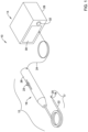
- FIG. 1 is a schematic block diagram of an illustrative atherectomy system
- FIG. 2 is a perspective view of an illustrative atherectomy burr usable in the illustrative atherectomy system of FIG. 1 ;
- FIG. 3 is a perspective view of an illustrative atherectomy burr usable in the illustrative atherectomy system of FIG. 1 ;
- FIG. 4 is a perspective view of an illustrative atherectomy burr usable in the illustrative atherectomy system of FIG. 1 ;
- FIG. 5 is an end view of an illustrative atherectomy burr usable in the illustrative atherectomy system of FIG. 1 ;
- FIG. 6 is an enlarged view of a portion of FIG. 5 ;
- FIG. 7 is a perspective view of an illustrative atherectomy burr usable in the illustrative atherectomy system of FIG. 1 ;
- FIG. 8 is a perspective view of an illustrative atherectomy burr usable in the illustrative atherectomy system of FIG. 1 ;
- FIG. 9 is a perspective view of an illustrative atherectomy burr usable in the illustrative atherectomy system of FIG. 1 ;
- FIG. 10 is a perspective view of an illustrative atherectomy burr usable in the illustrative atherectomy system of FIG. 1 ;
- FIG. 11 is a graph illustrating experimental data.
- Cardiovascular disease and peripheral arterial disease may arise from accumulation of atheromatous material on the inner walls of vascular lumens, resulting in a condition known as atherosclerosis.
- Atheromatous and other vascular deposits may restrict blood flow and can cause ischemia in a heart of a patient, vasculature of a patient's legs, a patient's carotid artery, etc.
- Such ischemia may lead to pain, swelling, wounds that will not heal, amputation, stroke, myocardial infarction, and/or other conditions.
- Atheromatous deposits may have widely varying properties, with some deposits being relatively soft or fatty, fibrous, or calcified. All are inelastic. The deposits may be referred to as plaque.
- Atherosclerosis occurs naturally as a result of aging, but may also be aggravated by factors such as diet, hypertension, heredity, vascular injury, and the like. Atherosclerosis may be treated in a variety of ways, including drugs, bypass surgery, and/or a variety of catheter-based approaches that may rely on intravascular widening or removal of the atheromatous or other material occluding the blood vessel. Atherectomy is a catheter-based intervention that may be used to treat atherosclerosis.
- Atherectomy is an interventional medical procedure performed to restore a flow of blood through a portion of a patient's vasculature that has been blocked by plaque or other material (e.g., blocked by an occlusion).
- a device on an end of a drive shaft is used to engage and/or remove (e.g., abrade, grind, cut, shave, etc.) plaque or other material from a patient's vessel (e.g., artery or vein).
- the device on an end of the drive shaft may be abrasive and/or may otherwise be configured to remove plaque from a vessel wall or other obstruction in a vessel when the device is rotating and engages the plaque or other obstruction.
- FIG. 1 depicts an atherectomy system 10 .
- the atherectomy system 10 may be electrically driven, pneumatically driven and/or driven in one or more other suitable manner. Additional or alternative components to those illustrated and described herein may be utilized in the operation of the atherectomy system 10 .
- the atherectomy system 10 may include a drive assembly 12 and a control unit 14 (e.g., a controller).
- the drive assembly 12 may include, among other elements, an advancer assembly 16 and a rotation assembly 17 .
- the control unit 14 is depicted as being separate from the drive assembly 12 in FIG. 1 , the functionality of the control unit 14 and the drive assembly 12 may be incorporated into a single component (e.g., in the advancer assembly 16 or other suitable single component).
- the rotation assembly 17 may include a drive shaft 18 (e.g., an elongate member that may be or may include a flexible drive shaft or other suitable drive shaft), an atherectomy burr 20 , and an elongate member 22 having a first end (e.g., a proximal end), a second end (e.g., a distal end), and a lumen extending from the first end to the second end for receiving the drive shaft 18 .
- the elongate member 22 may be an elongated tubular member.
- the atherectomy burr 20 may have a rough surface, such that it is configured to grind, abrade, etc. plaque from a vessel wall or other obstruction in a vessel when it is rotated.
- the advancer assembly 16 may include a knob 23 , a housing 26 , a drive mechanism (internal to the advancer assembly and thus not visible), and/or one or more other suitable components.
- the housing 26 may at least partially house the drive mechanism and the knob 23 may be at least partially accessible from an exterior of the housing 26 .
- the drive mechanism may be or may include a motor (e.g., an electric motor, pneumatic motor, or other suitable motor) at least partially housed within the housing 26 and in communication with the knob 23 , the drive shaft 18 , and the control unit 14 .
- the knob 23 may be configured to advance along a longitudinal path to longitudinally advance the drive mechanism and the rotation assembly 17 .
- the drive mechanism may be coupled to the drive shaft 18 in a suitable manner including, but not limited to, a weld connection, a clamping connection, an adhesive connection, a threaded connection, and/or other suitable connection configured to withstand rotational speeds and forces.
- a suitable manner including, but not limited to, a weld connection, a clamping connection, an adhesive connection, a threaded connection, and/or other suitable connection configured to withstand rotational speeds and forces.
- the drive shaft 18 may rotate over a wide range of speeds (e.g., at speeds of between zero (0) RPM and 250,000 RPM or higher)
- the coupling between the drive mechanism and the drive shaft 18 may be configured to withstand such rotational speeds and associated forces.
- the drive shaft 18 may be formed from one or more of a variety of materials.
- the drive shaft 18 may be formed from one or more of a variety of materials, including steel, stainless steel, other metal, polymer, and/or other suitable materials.
- the drive shaft 18 may have a suitable diameter and/or length for traversing vasculature of a patient.
- the diameter and/or the length of the drive shaft 18 may depend on the dimension of the lumen of the elongate member 22 , the dimensions of vessels of a patient to be traversed, and/or one or more other suitable factors.
- the drive shaft 18 may have a diameter in a range from about 0.030 centimeters (cm) or smaller to about 0.150 cm or larger and a working length in a range from about ten (10) cm or shorter to about three hundred (300) cm or longer.
- the drive shaft 18 may have a diameter of about 0.05715 cm and a length of about fifty (50) cm.
- the drive shaft 18 may have a different suitable diameter and/or different suitable length.
- the atherectomy burr 20 may have an outer perimeter which is equal to or larger than a distal diameter of the drive shaft 18 and/or the elongate member 22 .
- the atherectomy burr 20 may have an outer perimeter which is smaller than a diameter of the drive shaft 18 and/or the elongate member 22 .
- the atherectomy burr 20 may have a symmetric design so that it penetrates equally well in both rotational directions, but this is not required and the atherectomy burr 20 may be configured to penetrate in only one rotational direction.
- the atherectomy burr 20 may be coupled to the drive shaft 18 .
- the drive shaft 18 has a first end portion (e.g., a proximal end portion) and a second end portion (e.g., a distal end portion)
- the atherectomy burr 20 may be coupled to the drive shaft 18 at or near the second end portion.
- the atherectomy burr 20 may be located at or adjacent a terminal end of the second end portion of the drive shaft 18 .
- the atherectomy burr 20 may be coupled to the drive shaft 18 in any manner.
- the atherectomy burr 20 may be coupled to the drive shaft 18 with an adhesive connection, a threaded connection, a weld connection, a clamping connection, and/or other suitable connection configured to withstand rotational speeds and forces. Similar to as discussed above with respect to the connection between the drive shaft 18 and the drive mechanism, as the drive shaft 18 and/or the atherectomy burr 20 may rotate at speeds between zero (0) RPM and 250,000 RPM or higher, the coupling between the drive shaft 18 and the atherectomy burr 20 may be configured to withstand such rotational speeds and associated forces.
- the drive assembly 12 and the control unit 14 may be in communication and may be located in or may have a same housing and/or located in or have separate housings (e.g., the advancer assembly housing 26 and a control unit housing 28 or other housings). Whether in the same housing or in separate housings, the drive assembly 12 and the control unit 14 may be in communication through a wired connection (e.g., via one or more wires in an electrical connector 24 or other suitable electrical connector) and/or a wireless connection.
- a wired connection e.g., via one or more wires in an electrical connector 24 or other suitable electrical connector
- Wireless connections may be made via one or more communication protocols including, but not limited to, cellular communication, ZigBee, Bluetooth, Wi-Fi, Infrared Data Association (IrDA), dedicated short range communication (DSRC), EnOcean, and/or any other suitable common or proprietary wireless protocol, as desired.
- communication protocols including, but not limited to, cellular communication, ZigBee, Bluetooth, Wi-Fi, Infrared Data Association (IrDA), dedicated short range communication (DSRC), EnOcean, and/or any other suitable common or proprietary wireless protocol, as desired.
- the drive assembly 12 may include and/or enclose one or more operational features.
- the drive assembly 12 may include a motor (e.g., as discussed above and/or other suitable motor), rubber feet, control electronics, drive circuitry, etc.
- the control unit 14 which may be separate from the drive assembly 12 (e.g., as shown in FIG. 1 ) or may be included in the drive assembly 12 , may include several features.
- the control unit 14 may include a display 30 and a control knob 32 (e.g., a motor speed (e.g., RPM or other speed) adjustment knob or other control knob).
- a control knob 32 e.g., a motor speed (e.g., RPM or other speed) adjustment knob or other control knob.
- control unit 14 may include one or more other features for controlling the drive mechanism and/or other features of the drive assembly 12 (e.g., one or more drive mechanism states of the drive mechanism) including, but not limited to, a processor, memory, input/output devices, a speaker, volume control buttons, on/off power supply switch, motor activation switch, a timer, a clock, and/or one or more other features.
- control unit 14 may include one or more drive mechanism load output control mechanisms for controlling an operation of the atherectomy system 10 .
- the control unit 14 may include a mechanism configured to set and/or adjust an advancing load output (e.g., a rotational speed) and/or a retracting load output from the drive mechanism.
- the control unit 14 may include other control and/or safety mechanism for controlling the operation of the atherectomy system 10 and mitigating risks to patients.
- the atherectomy burr 20 may partially or even completely occlude blood flow through a vessel, particularly when the atherectomy burr 20 is abrading into and/or through a calcified occlusion.
- the atherectomy burr 20 may have a diameter that is in the range of 1.25 millimeters (mm) to 5 mm and a length that is in the range of 4 mm to 8 mm.
- the atherectomy burr 20 may be considered as being adapted to remove calcified material via abrasion, rather than by cutting.
- the atherectomy burr 20 may include an abrasive material secured to an outer surface of the atherectomy burr 20 . In some cases, the abrasive material may be diamond crystals or other diamond-based material.
- the atherectomy burr 20 may be adapted to permit blood flow through or past the atherectomy burr 20 in situations in which blood flow would be occluded, absent adaptations made to the atherectomy burr.
- FIGS. 2 through 8 provide illustrative but non-limiting examples of atherectomy burrs that include adaptations such as blood flow enhancement features that permit blood to flow through or around the atherectomy burr when the atherectomy burr is engaged within a blood vessel.
- FIG. 2 is a perspective view of an atherectomy burr 40 .
- the atherectomy burr 40 may be considered as being an example of the atherectomy burr 20 shown in FIG. 1 .
- the atherectomy burr 40 has a burr body 42 that extends from a distal region 44 to a proximal region 46 .
- the burr body 42 includes an outer surface 48 and a lumen 50 that extends through the burr body 42 .
- the atherectomy burr 40 includes blood flow enhancement features that permit blood flow through the atherectomy burr 40 that would not otherwise be feasible.
- the atherectomy burr 40 includes a first blood flow channel 52 and a second blood flow channel 54 . As shown, the first blood flow channel 52 and the second blood flow channel 54 are spaced about 180 degrees apart.
- the first blood flow channel 52 and the second blood flow channel 54 may each have a cylindrical shape and may exit through the proximal region 46 of the burr body 42 . At least one of the first blood flow channel 52 and the second blood flow channel 54 , and any additional blood flow channels, if included, may have an ovoid cross-sectional shape. In some instances, the first blood flow channel 52 and the second blood flow channel 54 , and any additional blood flow channels, if included, may have a circular cross-sectional shape, a rectilinear cross-sectional shape, a triangular cross-sectional shape, or any other desired cross-sectional shape. The first blood flow channel 52 and/or the second blood flow channel 54 may have a constant internal diameter.
- first blood flow channel 52 and/or the second blood flow channel 54 may have an internal diameter that increases moving proximally. In some cases, the first blood flow channel 52 and/or the second blood flow channel 54 may have an internal diameter that decreases moving proximally.
- the first blood flow channel 52 and/or the second blood flow channel 54 may have a circular cross-sectional shape having a diameter in the range of 0.0003 inches to 0.020 inches. In some cases, the first blood flow channel 52 and/or the second blood flow channel 54 may have a circular cross-sectional shape having a diameter that is at least partially dependent on the diameter of the atherectomy burr 40 .
- a larger diameter burr can accommodate a relatively larger diameter blood flow channel, for example, while a smaller diameter burr may be more limited with respect to the size of blood flow channel that can be accommodated.
- an atherectomy burr having a diameter of 1.5 millimeters may have blood flow channels having a diameter of 0.008 inches.
- An atherectomy burr having a diameter of 2.5 millimeters may have blood flow channels that are proportionally larger.
- An atherectomy burr having a diameter of 6 millimeters will also have blood flow channels that are proportionally larger.
- blood cells have an average diameter of about 0.0003 inches, which may be considered as a practical lower limit to the size of the blood flow channels 52 and 54 .
- making the blood flow channels 52 and 54 as large as possible can provide increased fluid flow through the atherectomy burr 40 , with relatively decreased frictional losses.
- frictional losses caused by boundary layers and other causes can substantially decrease fluid flow through the blood flow channels 52 and 54 .
- the openings to the first blood flow channel 52 and the second blood flow channel 54 may have rounded over edges, such that the edges do not damage blood cells flowing towards and into the first blood flow channel 52 and the second blood flow channel 54 .
- the openings to the first blood flow channel 52 and the second blood flow channel 54 may have a radius of curvature that is up to 1 millimeters for smaller diameter atherectomy burrs and a radius of curvature that is up to 10 millimeters for larger diameter burrs.
- the openings to the first blood flow channel 52 and the second blood flow channel 54 may have a radius of curvature in the range of 0.0001 inches to 0.020 inches.
- FIG. 6 provides an example defining what the radius of curvature is.
- FIG. 3 is a perspective view of an atherectomy burr 60 .
- the atherectomy burr 60 may be considered as being an example of the atherectomy burr 20 shown in FIG. 1 .
- the atherectomy burr 60 has a burr body 62 that extends from a distal region 64 to a proximal region 66 .
- the burr body 62 includes an outer surface 68 and a lumen 70 that extends through the burr body 62 .
- the atherectomy burr 60 includes blood flow enhancement features that permit blood flow through the atherectomy burr 60 that would not otherwise be feasible.
- the atherectomy burr 60 includes a single asymmetric cut 72 formed within the outer surface 68 .
- the single asymmetric cut 72 extends from the distal region 64 to the proximal region 66 .
- having a single asymmetric cut 72 means that the atherectomy burr 60 is off-balance.
- the atherectomy burr 60 when the atherectomy burr 60 rotates, the atherectomy burr 60 will not simply rotate in place, but will have an orbital path as it rotates. In some cases, this can mean that the atherectomy burr 60 may be able to create a larger hole through an occlusion than would otherwise be possible for a particular size of atherectomy burr 60 .
- the asymmetric cut 72 is shown in FIG. 3 as being straight, in some cases the asymmetric cut 72 could instead be spiral-shaped. In some cases, the asymmetric cut 72 may have a length that ranges from 10 percent up to 100 percent of a length of the atherectomy burr 60 . A width of the asymmetric cut 72 may be up to 50 percent of a circumference of the atherectomy burr 60 , with the circumference measured at a widest point of the atherectomy burr 60 . In some cases, the asymmetric cut 72 may have a depth that is up to 50 percent of a diameter of the atherectomy burr 60 , with the diameter measured at a widest point of the atherectomy burr 60 .
- the single asymmetric cut 72 has a semi-circular profile. In some cases, the single asymmetric cut 72 may have a flat or linear profile, as would result if one were to simply cut or grind away a portion of the curved burr body 62 . The single asymmetric cut 72 may have dimensions of up to 25 percent of the burr diameter. While a single asymmetric cut 72 is illustrated, in some cases the atherectomy burr 60 may include two or more asymmetric cuts 72 , spaced unequally around the burr body 62 . Depending on how much of an orbital path is desired, the relative spacing between the two or more asymmetric cuts 72 can be varied.
- the two asymmetric cuts 72 may be spaced 150 to 170 degrees apart (as opposed to 180 degrees, which would be symmetric). If a relatively larger orbital path is desired, the two asymmetric cuts 72 could be spaced 120 degrees part, for example. It will be appreciated that having a larger cut, or having multiple cuts, will improve blood flow past the atherectomy burr 60 but may reduce the available amount of abrasive material. In determining how far apart the asymmetric cuts are spaced, it should be noted that the burr body 62 has a largely cylindrical profile nearer its proximal region 66 and a tapered profile nearer its distal region 64 . Spacing may be considered as being defined within the largely cylindrical profile portion of the burr body 62 .
- the edges of the asymmetric cut 72 may be rounded over, such that the edges do not damage blood cells flowing towards and into the asymmetric cut 72 .
- the edges of the asymmetric cut 72 may have a radius of curvature that is up to 1 millimeters for smaller diameter atherectomy burrs and a radius of curvature that is up to 10 millimeters for larger diameter burrs.
- the edges of the asymmetric cut 72 may have a radius of curvature in the range of 0.0001 inches to 0.020 inches.
- FIG. 6 provides an example defining what the radius of curvature is.
- the first blood flow groove 92 and the second blood flow groove 94 are symmetrically arranged, being spaced 180 degrees apart. As a result, the first blood flow groove 92 and the second blood flow groove 94 will not materially alter the rotational patterns of the atherectomy burr 80 . While two blood flow grooves 92 , 94 are shown, it will be appreciated that there may be additional blood flow grooves.
- the atherectomy burr 80 could include a total of three blood flow grooves, each spaced 120 degrees apart. In determining how far apart the blood flow grooves are spaced, it should be noted that the burr body 82 has a largely cylindrical profile nearer its proximal region 86 and a tapered profile nearer its distal region 84 .
- Spacing may be considered as being defined within the largely cylindrical profile portion of the burr body 82 .
- the first blood flow groove 92 and the second blood flow groove 94 each have a semi-circular profile.
- Each of the first blood flow groove 92 and the second blood flow groove 94 may have dimensions of up to 25 percent of the burr diameter.
- the edges of the first blood flow groove 92 and the second blood flow groove 94 may be rounded over, such that the edges do not damage blood cells flowing towards and into the first blood flow groove 92 and the second blood flow groove 94 .
- the edges of the first blood flow groove 92 and the second blood flow groove 94 may each have a radius of curvature that is up to 1 millimeters for smaller diameter atherectomy burrs and a radius of curvature that is up to 10 millimeters for larger diameter burrs.
- the edges of the first blood flow groove 92 and the second blood flow groove 94 may have a radius of curvature in the range of 0.0001 inches to 0.020 inches.
- FIG. 6 provides an example defining what the radius of curvature is.
- FIG. 5 is a perspective view of an atherectomy burr 100 .
- the atherectomy burr 100 may be considered as being an example of the atherectomy burr 20 shown in FIG. 1 .
- the atherectomy burr 100 has a burr body 102 that includes an outer surface 104 and a lumen 106 that extends through the burr body 102 .
- the atherectomy burr 100 includes blood flow enhancement features that permit blood flow through the atherectomy burr 100 that would not otherwise be feasible.
- the atherectomy burr 100 includes a first blood flow groove 108 , a second blood flow groove 110 , a third blood flow groove 112 and a fourth blood flow groove 114 .
- the blood flow grooves 108 , 110 , 112 , 114 are equally spaced about the burr body 102 and are 90 degrees apart.
- each of the blood flow grooves 108 , 110 , 112 , 114 have a semi-circular profile. In some cases, it is contemplated that one or more of the blood flow grooves 108 , 110 , 112 , 114 could have a V-shaped profile, for example, or a rectilinear profile.
- FIG. 6 provides an enlarged view of the blood flow groove 108 as illustrative. As can be seen, the transition formed between the blood flow groove 108 and the outer surface 104 has a radius of curvature ‘r’ that limits or even prevents any part of the blood flow groove 108 from cutting or substantially cutting tissue.
- FIG. 7 is a perspective view of an atherectomy burr 120 .
- the atherectomy burr 120 may be considered as being an example of the atherectomy burr 20 shown in FIG. 1 .
- the atherectomy burr 120 has a burr body 122 that extends from a distal region 124 to a proximal region 126 .
- the burr body 122 includes an outer surface 128 and a lumen 131 that extends through the burr body 122 .
- the atherectomy burr 120 includes blood flow enhancement features that permit blood flow through the atherectomy burr 120 that would not otherwise be feasible.
- the atherectomy burr 120 includes a number of fluted cuts, including fluted cuts 130 , 132 , 134 , 136 and 138 that are visible in this illustration.
- the atherectomy burr 120 may include from two (2) to fifteen (14) fluted cuts.
- the atherectomy burr 120 may include from four (4) to ten (10) fluted cuts.
- the atherectomy burr 120 may include from six (6) to eight (8) fluted cuts.
- the atherectomy burr 120 may include a total of six (6) or eight (8) fluted cuts.
- Each of the fluted cuts 130 , 132 , 134 , 136 and 138 may have a length that ranges from ten (10) percent to one hundred (100) percent of a length of the atherectomy burr 120 .
- Each of the fluted cuts 130 , 132 , 134 , 136 and 138 may have a depth that ranges from near zero (0) to twenty five (25) percent of a diameter of the atherectomy burr 120 . In the case of a six (6) millimeter diameter atherectomy burr, the depth may be as great as forty (40) percent of the diameter.
- Each of the fluted cuts 130 , 132 , 134 , 136 and 138 may have a width that is up to fifty (50) percent of a diameter of the atherectomy burr 120 , with a caveat that a combined width (adding the width of each of the fluted cuts) does not exceed ninety (90) or ninety five (95) percent of the diameter of the atherectomy burr 120 .
- FIG. 8 is a perspective view of an atherectomy burr 140 .
- the atherectomy burr 140 may be considered as being an example of the atherectomy burr 20 shown in FIG. 1 .
- the atherectomy burr 140 has a burr body 142 that extends from a distal region 144 to a proximal region 146 .
- the burr body 142 includes an outer surface 148 and a lumen 151 that extends through the burr body 142 .
- the atherectomy burr 140 includes blood flow enhancement features that permit blood flow through the atherectomy burr 140 that would not otherwise be feasible.
- the atherectomy burr 140 includes a spiral blood flow groove 150 that extends from a distal end 152 that is disposed within the distal region 144 to a proximal end 154 (not visible).
- the spiral blood flow groove 150 may have a depth that is up to forty (40) or forty five (45) percent of a diameter of the atherectomy burr 140 .
- the spiral blood flow groove 150 has a rounded-over transition between the spiral blood flow groove 150 and the outer surface 148 such that the spiral blood flow groove 150 does not form any cutting edges, similar to that discussed with respect to FIG. 6 .
- FIG. 9 is a perspective view of an illustrative atherectomy burr 227 having a guidewire entry port 230 that is surrounded by a buffer zone 231 located at the front.
- the buffer zone 231 may be free of abrasive material.
- the atherectomy burr 227 includes a semi-spiral channel 210 having a low pitch, where pitch is defined as number of degrees of twist per centimeter of length.
- the semi-spiral channel 210 may serve to pump blood as the atherectomy burr 227 rotates in a direction indicated by an arrow 228 .
- the semi-spiral channel 231 pushes blood and debris distally, in a manner similar to that of a marine propeller. It will be appreciated that each element of the blood volume may receive a vector component of force in the distal direction.
- the semi-spiral channel 210 may have a leading edge 211 that is substantially rounded or chamfered over a distance that ranges from 0.02 to 10 times a width of the blood flow channel, or a distance that ranges from 0.05 to 10 times the width of the blood flow channel provided by the semi-spiral channel 210 .
- the leading edge 211 not provide a cutting feature, but the leading edge 211 also provides for a gradual return of rebounded tissue residing in the semi-spiral channel 210 to a surface 212 that is equal to the burr maximum at each position in the longitudinal direction.
- the tissue is not engaged by diamond crystals 232 until it has stabilized in an orbit equal to the burr's maximum radius of gyration.
- Differential cutting refers to a process whereby diseased tissue having inelastic properties is differentially removed while healthy tissue, which is elastic, is spared.
- FIG. 10 is a side view of an illustrative atherectomy burr 227 a having a guidewire entry port 230 that is surrounded by a buffer zone 231 located at the front.
- the buffer zone 231 may be free of abrasive material.
- the atherectomy burr 227 a includes a channel 210 a that is straight, but at a small angle with respect to a longitudinal axis 240 . With rotation in the direction indicated by the arrow 228 , blood will be pushed in the distal direction by the channel 210 a . As in FIG.
- the leading edge 211 a is substantially rounded or chamfered over a distance that ranges from 0.02 to 10 times a width of the blood flow channel provided by the channel 210 a , or a distance that ranges from 0.05 to 10 times the width of the blood flow channel.
- the leading edge 211 a does not provide a cutting feature, but the leading edge 211 a does provide for a gradual return of rebounded tissue residing in the channel 210 a to a surface 212 a that is equal to the burr maximum at each position in the longitudinal direction.
- the tissue is not engaged by diamond crystals 232 until it has stabilized in an orbit equal to the burr's maximum radius of gyration.
- Differential cutting refers to a process whereby diseased tissue having inelastic properties is differentially removed while healthy tissue, which is elastic, is spared.
- burr blanks were loaded onto a production equivalent 0.009 section of ROTAWIRE DRIVE and this subassembly was loaded into a clear HDPE tube with a 1.75 mm ID in a near straight configuration.
- the tube had a slight memory from being on spool and was flooded with red food coloring dyed DI water.
- Tubing was placed into a 6F compatible Hemostasis valve with Y-luer adapter port such that the proximal end of the tubing was just distal to the point in the hemostasis valve where the ‘y’ connects.
- the entry point on the hemostasis valve was closed and the ‘y’ port was connected to a 1 L bag of DI water and food coloring that was pressurized to 200 ⁇ 25 mmHg via pressure cuff, which was monitored and repressured at the start and during each test.
- the distal end of the tube was place over a collection beaker that had been wet weighed with the DI/food coloring mix.
- the pressurized bag was open as a timer was started. The burrs were not separately driven into rotation during testing.
- Fluid was collected in a beaker for roughly 30 seconds (within a margin of error for a human to close the IV line connecting the bag to the hemostasis valve.
- the fluid was weighed using a scale calibrated to ⁇ 0.5 g by weighing the beaker plus fluid and subtracting the weight of the empty beaker, where the empty beaker weighed 14.5 grams (g). Because water has a density of 1 g/ml, the net mass flow amounts listed below can also be considered as volumes, measured in milliliters (ml).
- the experimental data is shown below in Table One. The net mass data is graphically represented in FIG. 11 .
Landscapes
- Health & Medical Sciences (AREA)
- Surgery (AREA)
- Life Sciences & Earth Sciences (AREA)
- Biomedical Technology (AREA)
- Nuclear Medicine, Radiotherapy & Molecular Imaging (AREA)
- Engineering & Computer Science (AREA)
- Vascular Medicine (AREA)
- Heart & Thoracic Surgery (AREA)
- Medical Informatics (AREA)
- Molecular Biology (AREA)
- Animal Behavior & Ethology (AREA)
- General Health & Medical Sciences (AREA)
- Public Health (AREA)
- Veterinary Medicine (AREA)
- Surgical Instruments (AREA)
Abstract
Description
| TABLE ONE | |||||
| Control | Fluted | Scallop | Through Hole | ||
| Gross | Net | Gross | Net | Gross | Net | Gross | Net | |
| Run | Weight | Weight | Weight | Weight | Weight | Weight | Weight | Weight |
| # | (g) | (g) | (g) | Net (g) | (g) | (g) | (g) | (g) |
| 1 | 64 | 49.5 | 84.5 | 70 | 75 | 60.5 | 59.5 | 45 |
| 2 | 68.5 | 54 | 98 | 83.5 | 73 | 58.5 | 76 | 61.5 |
| 3 | 86 | 74.5 | 134 | 119.5 | 74 | 59.5 | 66.5 | 52 |
| 4 | 82.5 | 68 | 138.5 | 124 | 71.5 | 57 | 111.5 | 97 |
| 5 | 88 | 73.5 | 69 | 54.5 | 73.5 | 59 | 91.5 | 77 |
Claims (6)
Priority Applications (1)
| Application Number | Priority Date | Filing Date | Title |
|---|---|---|---|
| US17/514,368 US12171457B2 (en) | 2020-10-30 | 2021-10-29 | Atherectomy burrs with blood flow enhancements |
Applications Claiming Priority (2)
| Application Number | Priority Date | Filing Date | Title |
|---|---|---|---|
| US202063108045P | 2020-10-30 | 2020-10-30 | |
| US17/514,368 US12171457B2 (en) | 2020-10-30 | 2021-10-29 | Atherectomy burrs with blood flow enhancements |
Publications (2)
| Publication Number | Publication Date |
|---|---|
| US20220133347A1 US20220133347A1 (en) | 2022-05-05 |
| US12171457B2 true US12171457B2 (en) | 2024-12-24 |
Family
ID=78771202
Family Applications (1)
| Application Number | Title | Priority Date | Filing Date |
|---|---|---|---|
| US17/514,368 Active 2042-03-08 US12171457B2 (en) | 2020-10-30 | 2021-10-29 | Atherectomy burrs with blood flow enhancements |
Country Status (4)
| Country | Link |
|---|---|
| US (1) | US12171457B2 (en) |
| EP (1) | EP4236837A1 (en) |
| CN (1) | CN116685279A (en) |
| WO (1) | WO2022094228A1 (en) |
Families Citing this family (1)
| Publication number | Priority date | Publication date | Assignee | Title |
|---|---|---|---|---|
| CN118453047A (en) * | 2024-04-16 | 2024-08-09 | 广东工业大学 | Interventional type rotary grinding instrument and manufacturing method thereof |
Citations (243)
| Publication number | Priority date | Publication date | Assignee | Title |
|---|---|---|---|---|
| US2088654A (en) | 1935-02-16 | 1937-08-03 | Sperry Gyroscope Co Inc | Position control system |
| US3913196A (en) | 1974-08-29 | 1975-10-21 | Lear Siegler Inc | Rotary cutting tool |
| US3937222A (en) * | 1973-11-09 | 1976-02-10 | Surgical Design Corporation | Surgical instrument employing cutter means |
| US4395167A (en) | 1981-03-09 | 1983-07-26 | National Carbide Tool, Inc. | Router especially for use as a fiber-metal cutter |
| US4507028A (en) | 1981-09-26 | 1985-03-26 | Densaburo Sakai | Combined drill and reamer |
| US4679557A (en) | 1984-09-10 | 1987-07-14 | E. R. Squibb & Sons, Inc. | Electrodynamic transluminal angioplasty system |
| US4990134A (en) * | 1986-01-06 | 1991-02-05 | Heart Technology, Inc. | Transluminal microdissection device |
| US5116350A (en) | 1987-03-17 | 1992-05-26 | Cordis Corporation | Catheter system having distal tip for opening obstructions |
| US5287858A (en) | 1992-09-23 | 1994-02-22 | Pilot Cardiovascular Systems, Inc. | Rotational atherectomy guidewire |
| US5308354A (en) | 1991-07-15 | 1994-05-03 | Zacca Nadim M | Atherectomy and angioplasty method and apparatus |
| US5314407A (en) | 1986-11-14 | 1994-05-24 | Heart Technology, Inc. | Clinically practical rotational angioplasty system |
| US5417703A (en) | 1993-07-13 | 1995-05-23 | Scimed Life Systems, Inc. | Thrombectomy devices and methods of using same |
| US5478344A (en) | 1993-10-08 | 1995-12-26 | United States Surgical Corporation | Surgical suturing apparatus with loading mechanism |
| US5501694A (en) | 1992-11-13 | 1996-03-26 | Scimed Life Systems, Inc. | Expandable intravascular occlusion material removal devices and methods of use |
| US5540707A (en) | 1992-11-13 | 1996-07-30 | Scimed Life Systems, Inc. | Expandable intravascular occlusion material removal devices and methods of use |
| WO1996029014A1 (en) | 1995-03-22 | 1996-09-26 | Evi Corporation | Intra-artery obstruction clearing apparatus and methods |
| US5563481A (en) | 1992-04-13 | 1996-10-08 | Smith & Nephew Endoscopy, Inc. | Brushless motor |
| US5572609A (en) | 1995-09-01 | 1996-11-05 | University Of Maryland | Optical fiber vibration modal filter for flexible structures produced by the photorefractive effect |
| US5626444A (en) | 1994-03-09 | 1997-05-06 | Campian; Jonathon | Rotary cutting tool |
| US5632755A (en) * | 1992-11-09 | 1997-05-27 | Endo Vascular Intruments, Inc. | Intra-artery obstruction clearing apparatus and methods |
| US5674235A (en) | 1995-05-10 | 1997-10-07 | Ultralase Technologies International | Ultrasonic surgical cutting instrument |
| US5681336A (en) | 1995-09-07 | 1997-10-28 | Boston Scientific Corporation | Therapeutic device for treating vien graft lesions |
| US5709661A (en) | 1992-04-14 | 1998-01-20 | Endo Sonics Europe B.V. | Electronic catheter displacement sensor |
| WO1998014124A1 (en) | 1996-10-04 | 1998-04-09 | Klieman Charles H | Surgical instrument for endoscopic and general surgery |
| US5766192A (en) | 1995-10-20 | 1998-06-16 | Zacca; Nadim M. | Atherectomy, angioplasty and stent method and apparatus |
| US5779722A (en) | 1997-01-21 | 1998-07-14 | Shturman Cardiology Systems, Inc. | Atherectomy device handle with guide wire clamp override device |
| US5823990A (en) | 1997-01-16 | 1998-10-20 | Henley; Julian L. | Ultrasonic liposuction handpiece |
| US5836868A (en) | 1992-11-13 | 1998-11-17 | Scimed Life Systems, Inc. | Expandable intravascular occlusion material removal devices and methods of use |
| US5899915A (en) | 1996-12-02 | 1999-05-04 | Angiotrax, Inc. | Apparatus and method for intraoperatively performing surgery |
| US5913867A (en) | 1996-12-23 | 1999-06-22 | Smith & Nephew, Inc. | Surgical instrument |
| US6015420A (en) | 1997-03-06 | 2000-01-18 | Scimed Life Systems, Inc. | Atherectomy device for reducing damage to vessels and/or in-vivo stents |
| US6017354A (en) | 1996-08-15 | 2000-01-25 | Stryker Corporation | Integrated system for powered surgical tools |
| US6086608A (en) | 1996-02-22 | 2000-07-11 | Smith & Nephew, Inc. | Suture collet |
| US6102926A (en) | 1996-12-02 | 2000-08-15 | Angiotrax, Inc. | Apparatus for percutaneously performing myocardial revascularization having means for sensing tissue parameters and methods of use |
| US6106301A (en) | 1996-09-04 | 2000-08-22 | Ht Medical Systems, Inc. | Interventional radiology interface apparatus and method |
| US6113615A (en) | 1999-02-03 | 2000-09-05 | Scimed Life Systems, Inc. | Atherectomy burr including a bias wire |
| WO2000051511A1 (en) | 1999-03-02 | 2000-09-08 | Atrionix, Inc. | Positioning system for a pulmonary ostium ablator |
| US6120515A (en) | 1996-02-06 | 2000-09-19 | Devices For Vascular Intervention, Inc. | Composite atherectomy cutter |
| WO2000056230A2 (en) | 1999-03-19 | 2000-09-28 | Scimed Life Systems Inc | Atherectomy power control system |
| US6126667A (en) | 1999-10-01 | 2000-10-03 | Scimed Life Systems, Inc. | Articulated ablation device |
| US6139510A (en) | 1994-05-11 | 2000-10-31 | Target Therapeutics Inc. | Super elastic alloy guidewire |
| US6149663A (en) | 1999-08-17 | 2000-11-21 | Scimed Life Systems, Inc. | Guide wire brake for ablation assembly |
| US6171312B1 (en) | 1996-07-18 | 2001-01-09 | Implant Innovations, Inc. | Power-driven osteotome tools for compaction of bone tissue |
| US6200329B1 (en) | 1998-08-31 | 2001-03-13 | Smith & Nephew, Inc. | Suture collet |
| US6212300B1 (en) | 1997-06-06 | 2001-04-03 | Canon Kabushiki Kaisha | Image processing apparatus, method and computer-executable program product for converting the format of data for specific image data |
| US6234725B1 (en) | 1999-12-14 | 2001-05-22 | Jonathan R. Campian | Rotary cutting tool |
| US20010004700A1 (en) | 1998-04-10 | 2001-06-21 | Honeycutt John S. | Rotational atherectomy device |
| WO2001054595A1 (en) | 2000-01-31 | 2001-08-02 | Rex Medical, Lp | Atherectomy device and methods |
| US6270509B1 (en) * | 1997-03-06 | 2001-08-07 | Scimed Life Systems, Inc. | Cancave atherectomy burr with smooth rims |
| US20010037121A1 (en) | 2000-01-31 | 2001-11-01 | Mcguckin James F. | Atherectomy device |
| US6312438B1 (en) | 2000-02-01 | 2001-11-06 | Medtronic Xomed, Inc. | Rotary bur instruments having bur tips with aspiration passages |
| WO2001089393A1 (en) | 2000-05-19 | 2001-11-29 | C.R. Bard, Inc. | Tissue capturing and suturing device and method |
| US20020007190A1 (en) * | 2000-04-05 | 2002-01-17 | Wulfman Edward I. | Intralumenal material removal systems and methods |
| US20020058956A1 (en) | 1999-09-17 | 2002-05-16 | John S. Honeycutt | Rotational atherectomy system with side balloon |
| WO2002049518A2 (en) | 2000-12-18 | 2002-06-27 | Scimed Life Systems, Inc. | Atherectomy burr with micro-engineered cutting surfaces |
| US20020107530A1 (en) | 2001-02-02 | 2002-08-08 | Sauer Jude S. | System for endoscopic suturing |
| US20020151917A1 (en) | 2001-04-12 | 2002-10-17 | Scimed Life Systems, Inc. | Ablation system with catheter clearing abrasive |
| US20020161384A1 (en) | 2001-04-30 | 2002-10-31 | Scimed Life Systems, Inc., A Minnesota Corporation | Ablation assembly with elastomeric driveshaft connection |
| US6494888B1 (en) | 1999-06-22 | 2002-12-17 | Ndo Surgical, Inc. | Tissue reconfiguration |
| US6500186B2 (en) | 2001-04-17 | 2002-12-31 | Scimed Life Systems, Inc. | In-stent ablative tool |
| US6503261B1 (en) | 2001-01-17 | 2003-01-07 | Scimed Life Systems, Inc. | Bi-directional atherectomy burr |
| US6503227B1 (en) | 2000-07-24 | 2003-01-07 | Scimed Life Systems, Inc. | Guide wire brake |
| US6506196B1 (en) | 1999-06-22 | 2003-01-14 | Ndo Surgical, Inc. | Device and method for correction of a painful body defect |
| US6554845B1 (en) | 2000-09-15 | 2003-04-29 | PARÉ Surgical, Inc. | Suturing apparatus and method |
| US20030093103A1 (en) | 2001-08-08 | 2003-05-15 | Don Malackowski | Surgical tool system with components that perform inductive data transfer |
| US6569085B2 (en) | 2001-08-16 | 2003-05-27 | Syntheon, Llc | Methods and apparatus for delivering a medical instrument over an endoscope while the endoscope is in a body lumen |
| US6579298B1 (en) * | 2000-02-29 | 2003-06-17 | Scimed Life Systems, Inc. | Method and apparatus for treating vein graft lesions |
| US6626917B1 (en) | 1999-10-26 | 2003-09-30 | H. Randall Craig | Helical suture instrument |
| US20030204205A1 (en) | 2001-02-02 | 2003-10-30 | Lsi Solutions, Inc. | Crimping instrument with motion limiting feature |
| US6663639B1 (en) | 1999-06-22 | 2003-12-16 | Ndo Surgical, Inc. | Methods and devices for tissue reconfiguration |
| US20040002699A1 (en) | 2002-06-27 | 2004-01-01 | Ethicon, Inc. | Helical device and method for aiding the ablation and assessment of tissue |
| US20040068270A1 (en) | 2002-10-02 | 2004-04-08 | Advanced Medical Optics, Inc. | Handpiece system for multiple phacoemulsification techniques |
| US6719763B2 (en) | 2000-09-29 | 2004-04-13 | Olympus Optical Co., Ltd. | Endoscopic suturing device |
| US6740030B2 (en) | 2002-01-04 | 2004-05-25 | Vision Sciences, Inc. | Endoscope assemblies having working channels with reduced bending and stretching resistance |
| US6746457B2 (en) | 2001-12-07 | 2004-06-08 | Abbott Laboratories | Snared suture trimmer |
| US6755843B2 (en) | 2000-09-29 | 2004-06-29 | Olympus Optical Co., Ltd. | Endoscopic suturing device |
| US20040138706A1 (en) | 2003-01-09 | 2004-07-15 | Jeffrey Abrams | Knotless suture anchor |
| WO2004080507A2 (en) | 2003-03-10 | 2004-09-23 | Pathway Medical Technologies, Inc. | Interventional catheters assemblies and control systems |
| US20040186368A1 (en) | 2003-03-21 | 2004-09-23 | Scimed Life Systems, Inc. | Systems and methods for internal tissue penetration |
| US6808491B2 (en) | 2001-05-21 | 2004-10-26 | Syntheon, Llc | Methods and apparatus for on-endoscope instruments having end effectors and combinations of on-endoscope and through-endoscope instruments |
| US6821285B2 (en) | 1999-06-22 | 2004-11-23 | Ndo Surgical, Inc. | Tissue reconfiguration |
| US6835200B2 (en) | 1999-06-22 | 2004-12-28 | Ndo Surgical. Inc. | Method and devices for tissue reconfiguration |
| US20050004579A1 (en) | 2003-06-27 | 2005-01-06 | Schneider M. Bret | Computer-assisted manipulation of catheters and guide wires |
| US20050015021A1 (en) | 2003-07-16 | 2005-01-20 | Samuel Shiber | Guidewire system with exposed midsection |
| US20050033319A1 (en) | 2003-05-16 | 2005-02-10 | Gambale Richard A. | Single intubation, multi-stitch endoscopic suturing system |
| EP1520509A1 (en) | 2003-09-30 | 2005-04-06 | Olympus Corporation | Adaptor for endoscope forceps opening |
| US6908427B2 (en) | 2002-12-30 | 2005-06-21 | PARÉ Surgical, Inc. | Flexible endoscope capsule |
| US20050240146A1 (en) | 2004-04-27 | 2005-10-27 | Nash John E | Thrombectomy and soft debris removal device |
| US20050250985A1 (en) | 2004-05-07 | 2005-11-10 | Usgi Medical Inc. | Self-locking removable apparatus and methods for manipulating and securing tissue |
| US20060074442A1 (en) | 2000-04-06 | 2006-04-06 | Revascular Therapeutics, Inc. | Guidewire for crossing occlusions or stenoses |
| US20060074405A1 (en) | 2004-09-29 | 2006-04-06 | Don Malackowski | Integrated system for controlling plural surgical tools |
| US7063710B2 (en) | 2002-04-15 | 2006-06-20 | Nipro Corporation | Intracardiac suture device |
| US7063715B2 (en) | 2002-07-11 | 2006-06-20 | Olympus Corporation | Endoscopic suture apparatus |
| US20060142775A1 (en) | 2004-12-29 | 2006-06-29 | Depuy Mitek, Inc. | Surgical tool with cannulated rotary tip |
| US7094246B2 (en) | 2001-12-07 | 2006-08-22 | Abbott Laboratories | Suture trimmer |
| US7144401B2 (en) | 2001-06-07 | 2006-12-05 | Olympus Optical Co., Ltd. | Suturing device for endoscope |
| US20070093841A1 (en) | 2005-09-23 | 2007-04-26 | Thomas Hoogland | Surgical drill, a set of surgical drills, a system for cutting bone and a method for removing bone |
| US7220266B2 (en) | 2000-05-19 | 2007-05-22 | C. R. Bard, Inc. | Tissue capturing and suturing device and method |
| US7232445B2 (en) | 2000-12-06 | 2007-06-19 | Id, Llc | Apparatus for the endoluminal treatment of gastroesophageal reflux disease (GERD) |
| US20070239140A1 (en) | 2006-03-22 | 2007-10-11 | Revascular Therapeutics Inc. | Controller system for crossing vascular occlusions |
| US7285130B2 (en) | 2004-04-27 | 2007-10-23 | Boston Scientific Scimed, Inc. | Stent delivery system |
| US20070270908A1 (en) | 2006-05-19 | 2007-11-22 | Stokes Michael J | Suture locking method |
| US7326221B2 (en) | 2004-04-07 | 2008-02-05 | Olympus Corporation | Ligature and suture device for medical application, and ligaturing and suturing method for medical application |
| WO2008016592A2 (en) | 2006-08-01 | 2008-02-07 | Wilson-Cook Medical Inc. | Improved system and method for endoscopic treatment of tissue |
| US20080039823A1 (en) | 2006-02-14 | 2008-02-14 | Asahi Intecc Co. Ltd. | Medical Equipment, Tubular Insertion Device and Tubular Insertion Device Having the Same Medical Equipment |
| US7344545B2 (en) | 2002-01-30 | 2008-03-18 | Olympus Corporation | Endoscopic suturing system |
| US7347863B2 (en) | 2004-05-07 | 2008-03-25 | Usgi Medical, Inc. | Apparatus and methods for manipulating and securing tissue |
| US20080086148A1 (en) | 2006-10-04 | 2008-04-10 | Endogastric Solutions, Inc. | Assemblies for deploying fasteners in tissue and snares for use in such assemblies |
| WO2008045376A2 (en) | 2006-10-05 | 2008-04-17 | Tyco Healthcare Group Lp | Axial stitching device |
| US7361180B2 (en) | 2004-05-07 | 2008-04-22 | Usgi Medical, Inc. | Apparatus for manipulating and securing tissue |
| US20080097499A1 (en) | 2004-04-27 | 2008-04-24 | Nash John E | Thrombectomy and soft debris removal device |
| US20080103516A1 (en) * | 2006-10-04 | 2008-05-01 | Pathway Medical Technologies, Inc. | Interventional catheters having cutter assemblies and differential cutting surfaces for use in such assemblies |
| US20080146965A1 (en) | 2003-08-11 | 2008-06-19 | Salvatore Privitera | Surgical Device for The Collection of Soft Tissue |
| WO2008098124A1 (en) | 2007-02-07 | 2008-08-14 | Boston Scientific Scimed, Inc. | Attachment clamp |
| CA2682488A1 (en) | 2007-03-30 | 2008-10-09 | Wilson Cook Medical Inc. | Endoscopic securing system |
| EP2011446A2 (en) | 2000-09-22 | 2009-01-07 | Salient Surgical Technologies, Inc. | Fluid-assisted medical device |
| US20090024085A1 (en) | 2006-06-30 | 2009-01-22 | Artheromed, Inc | Atherectomy devices, systems, and methods |
| US20090069829A1 (en) | 2005-05-26 | 2009-03-12 | Leonid Shturman | Rotational Atherectomy Device with Distal Protection Capability and Method of Use |
| US7530985B2 (en) | 2002-01-30 | 2009-05-12 | Olympus Corporation | Endoscopic suturing system |
| US20090124975A1 (en) | 2007-11-12 | 2009-05-14 | Oliver Dana A | Systems and methods for surgical removal of brain tumors |
| US20090177031A1 (en) | 2008-01-03 | 2009-07-09 | Wilson-Cook Medical Inc. | Medical systems, devices and methods for endoscopically suturing perforations |
| US7601161B1 (en) | 1999-07-02 | 2009-10-13 | Quick Pass, Inc. | Suturing device |
| EP2108304A2 (en) | 2008-04-10 | 2009-10-14 | Olympus Medical Systems Corporation | Medical treatment system and suturing method |
| US7618425B2 (en) | 2002-01-30 | 2009-11-17 | Olympus Corporation | Endoscopic suturing system |
| US20090299392A1 (en) * | 2008-05-30 | 2009-12-03 | Cardiovascular Systems, Inc. | Eccentric abrading element for high-speed rotational atherectomy devices |
| WO2010036227A1 (en) | 2008-09-29 | 2010-04-01 | C R . Bard, Inc . | Endoscopic suturing device |
| WO2010056714A1 (en) | 2008-11-14 | 2010-05-20 | Revascular Therapeutics Inc. | Method and system for reversibly controlled drilling of luminal occlusions |
| US7727246B2 (en) | 2000-12-06 | 2010-06-01 | Ethicon Endo-Surgery, Inc. | Methods for endoluminal treatment |
| US20100137681A1 (en) | 2008-11-21 | 2010-06-03 | Usgi Medical, Inc. | Endoscopic instrument management system |
| US20100198006A1 (en) | 2003-09-15 | 2010-08-05 | Benny Greenburg | System Of Accessories For Use With Bronchoscopes |
| WO2010089727A1 (en) | 2009-02-09 | 2010-08-12 | Yuval Jacoby | Intravenous cannula |
| US20100292720A1 (en) * | 2009-05-12 | 2010-11-18 | Cardiovascular Systems, Inc. | Rotational atherectomy device and method to improve abrading efficiency |
| US7846180B2 (en) | 1999-06-22 | 2010-12-07 | Ethicon Endo-Surgery, Inc. | Tissue fixation devices and methods of fixing tissue |
| US20100312263A1 (en) | 2009-04-29 | 2010-12-09 | Fox Hollow Technologies, Inc. | Methods and devices for cutting and abrading tissue |
| US20110077673A1 (en) | 2009-09-29 | 2011-03-31 | Cardiovascular Systems, Inc. | Rotational atherectomy device with frictional clutch having magnetic normal force |
| US7918867B2 (en) | 2001-12-07 | 2011-04-05 | Abbott Laboratories | Suture trimmer |
| WO2011060192A1 (en) | 2009-11-13 | 2011-05-19 | Interlace Medical, Inc. | Access system with removable outflow channel |
| US7993368B2 (en) | 2003-03-13 | 2011-08-09 | C.R. Bard, Inc. | Suture clips, delivery devices and methods |
| WO2011106053A1 (en) | 2010-02-26 | 2011-09-01 | Cardiovascular Systems, Inc. | Rotational atherectomy device with electric motor |
| US20110251554A1 (en) | 2010-04-09 | 2011-10-13 | Alexandre Romoscanu | Control handle for a contact force ablation catheter |
| US8062314B2 (en) | 2000-12-06 | 2011-11-22 | Ethicon Endo-Surgery, Inc. | Methods for the endoluminal treatment of gastroesophageal reflux disease (GERD) |
| US20110306995A1 (en) | 2010-06-14 | 2011-12-15 | Tyco Healthcare Group Lp | Material removal device and method of use |
| US8087856B2 (en) | 2006-09-22 | 2012-01-03 | Reed Gary J | Double helix thread cutting tap |
| US8105355B2 (en) | 2006-05-18 | 2012-01-31 | C.R. Bard, Inc. | Suture lock fastening device |
| US20120046600A1 (en) * | 2010-02-25 | 2012-02-23 | Cardiovascular Systems, Inc. | High-speed rotational atherectomy system, device and method for localized application of therapeutic agents to a biological conduit |
| US20120053606A1 (en) | 2008-06-23 | 2012-03-01 | Schmitz Gregory P | Selective tissue removal tool for use in medical applications and methods for making and using |
| US20120095461A1 (en) | 2010-04-09 | 2012-04-19 | Minnow Medical, Inc. | Power generating and control apparatus for the treatment of tissue |
| DE202005022017U1 (en) | 2005-12-22 | 2012-05-10 | Hugh S., jun. West | Bone Anchor with threaded structure optimized for fixation in cortical bone tissue and cancellous bone tissue |
| US20120130410A1 (en) | 2010-11-15 | 2012-05-24 | Vascular Insights Llc | Direction reversing vascular treatment device |
| US20120136348A1 (en) | 2010-11-29 | 2012-05-31 | Medtronic Ablation Frontiers Llc | System and Method for Adaptive RF Ablation |
| US20120158023A1 (en) | 2010-12-16 | 2012-06-21 | Vladimir Mitelberg | Endoscopic Suture Cinch System |
| US8211123B2 (en) | 2001-12-21 | 2012-07-03 | Abbott Laboratories | Suture trimmer |
| US20120172963A1 (en) | 2007-07-16 | 2012-07-05 | Michael Ryan | Delivery device |
| US20120179167A1 (en) | 2010-09-17 | 2012-07-12 | Corindus Inc. | Robotic catheter system |
| US20120185031A1 (en) | 2011-01-19 | 2012-07-19 | Michael Ryan | Rotary and linear handle mechanism for constrained stent delivery system |
| US20120209176A1 (en) | 2011-02-09 | 2012-08-16 | Boston Scientific Scimed, Inc. | Balloon catheter |
| EP2508141A1 (en) | 2007-04-16 | 2012-10-10 | Smith & Nephew, Inc. | Powered surgical system |
| US8287556B2 (en) | 2008-06-17 | 2012-10-16 | Apollo Endosurgery, Inc. | Endoscopic suturing system |
| US8287554B2 (en) | 1999-06-22 | 2012-10-16 | Ethicon Endo-Surgery, Inc. | Method and devices for tissue reconfiguration |
| US20120271327A1 (en) | 2008-06-17 | 2012-10-25 | Stephen West | Endoscopic Tissue Grasping Systems and Methods |
| US8308765B2 (en) | 2004-05-07 | 2012-11-13 | Usgi Medical, Inc. | Apparatus and methods for positioning and securing anchors |
| US8313496B2 (en) | 2001-02-02 | 2012-11-20 | Lsi Solutions, Inc. | System for endoscopic suturing |
| US20130006248A1 (en) | 2010-03-19 | 2013-01-03 | CPL Holdings Pty. Ltd. | Drill bit |
| US8361089B2 (en) | 2002-07-22 | 2013-01-29 | Boston Scientific Scimed, Inc. | Placing sutures |
| US20130079763A1 (en) | 2011-09-28 | 2013-03-28 | Tyco Healthcare Group Lp | Logarithmic Amplifier, Electrosurgical Generator Including Same, and Method of Controlling Electrosurgical Generator Using Same |
| US20130103062A1 (en) | 2006-06-30 | 2013-04-25 | Atheromed, Inc. | Atherectomy devices and methods |
| US20130253552A1 (en) | 2012-03-20 | 2013-09-26 | Cardiovascular Systems, Inc. | Controller for an atherectomy device |
| US8556914B2 (en) | 2006-12-15 | 2013-10-15 | Boston Scientific Scimed, Inc. | Medical device including structure for crossing an occlusion in a vessel |
| US20130274657A1 (en) | 2010-09-17 | 2013-10-17 | Corindus, Inc. | Wheel for robotic catheter system drive mechanism |
| WO2013158849A2 (en) | 2012-04-20 | 2013-10-24 | Linestream Technologies | Method for automatically estimating inertia in a mechanical system and for generating a motion profile |
| US20130304093A1 (en) | 2007-10-19 | 2013-11-14 | Guided Delivery Systems Inc. | Devices and methods for termination |
| US8603123B2 (en) | 2008-04-28 | 2013-12-10 | Urotech, Inc. | Benign prostatic hyperplasia surgical system featuring mechanical coring probe with live aspiration |
| US8679136B2 (en) | 2008-06-17 | 2014-03-25 | Apollo Endosurgery, Inc. | Needle capture device |
| US20140100574A1 (en) | 2012-10-08 | 2014-04-10 | Peter Bono | Cutting tool for bone, cartilage, and disk removal |
| US8709022B2 (en) | 2011-05-24 | 2014-04-29 | Biomet Sports Medicine, Llc | Method and apparatus for passing a suture |
| US20140128668A1 (en) | 2009-09-03 | 2014-05-08 | Usgi Medical, Inc. | Devices and methods for endolumenal weight loss treatments |
| US20140148835A1 (en) | 2012-11-29 | 2014-05-29 | Gregory P. Schmitz | Micro debrider devices and methods of tissue removal |
| WO2014106847A1 (en) | 2013-01-07 | 2014-07-10 | Taryag Medical Ltd. | Expandable atherectomy device |
| US20140212457A1 (en) | 2005-09-06 | 2014-07-31 | Abdalla Rifai | Compounds |
| US20140222042A1 (en) | 2012-11-08 | 2014-08-07 | Covidien Lp | Tissue-Removing Catheter Including Operational Control Mechanism |
| US20140249554A1 (en) | 2006-06-30 | 2014-09-04 | Atheromed, Inc. | Atherectomy devices and methods |
| US20140277014A1 (en) | 2013-03-15 | 2014-09-18 | Cardiovascular Systems, Inc. | Rotational atherectomy device with biasing clutch |
| US20140261453A1 (en) | 2013-03-12 | 2014-09-18 | Hansen Medical, Inc. | Noncontact encoder for measuring catheter insertion |
| US20140316451A1 (en) | 2013-03-15 | 2014-10-23 | Cardiovascular Systems, Inc. | Rotational atherectomy device with biasing clutch |
| US20140316447A1 (en) | 2013-03-14 | 2014-10-23 | Cardiovascular Systems, Inc. | Devices, systems and methods for a piloting tip bushing for rotational atherectomy |
| US20140316448A1 (en) | 2013-03-14 | 2014-10-23 | Cardiovascular Systems, Inc. | Devices, systems and methods for a guide wire loader |
| US20140324052A1 (en) | 2004-03-03 | 2014-10-30 | Boston Scientific Scimed, Inc. | Apparatus and methods for removing vertebral bone and disc tissue |
| US20150011834A1 (en) | 2003-07-31 | 2015-01-08 | Cook Medical Technologies Llc | System and method for introducing multiple medical devices |
| US20150073448A1 (en) | 2013-07-25 | 2015-03-12 | Cardiovascular Systems, Inc. | Rotational atherectomy device with exchangeable drive shaft and meshing gears |
| US9011466B2 (en) | 2009-01-26 | 2015-04-21 | DePuy Synthes Products, Inc. | Bi-directional suture passer |
| US20150125807A1 (en) | 2012-04-06 | 2015-05-07 | Aseptico Inc. | Method for cutting or abrading with a tool, and related drivers and systems |
| US20150126983A1 (en) | 2013-11-05 | 2015-05-07 | Apollo Endosurgery, Inc. | Incisionless Endoluminal Gastric Tissue Approximation for the Treatment Of Obesity |
| US9050127B2 (en) | 2012-06-27 | 2015-06-09 | Boston Scientific Limited | Consolidated atherectomy and thrombectomy catheter |
| US20150164540A1 (en) | 2013-07-25 | 2015-06-18 | Cardiovascular Systems, Inc. | Rotational atherectomy device with exchangeable drive shaft and meshing gears |
| US20150173838A1 (en) | 2011-09-20 | 2015-06-25 | Corindus, Inc. | Variable drive force apparatus and method for robotic catheter system |
| US20150173776A1 (en) | 2012-09-07 | 2015-06-25 | Stryker Ireland, Ltd. | Surgical bur with plural flutes and a groove, the groove formed in a single one of the flutes and spaced away from the distal end of the bur |
| US20150201956A1 (en) | 2014-01-17 | 2015-07-23 | Cardiovascular Systems, Inc. | Spin-to-open atherectomy device with electric motor control |
| US20150216554A1 (en) | 2014-02-03 | 2015-08-06 | Covidien Lp | Tissue-removing catheter including angular displacement sensor |
| US9125646B2 (en) | 2010-11-15 | 2015-09-08 | Ethicon Endo-Surgery, Inc. | Needle for laparoscopic suturing instrument |
| US20150327880A1 (en) | 2014-05-13 | 2015-11-19 | Acclarent, Inc. | Apparatus and Method for Treating Disorders of the Ear, Nose and Throat |
| WO2016001932A1 (en) | 2014-07-03 | 2016-01-07 | Taryag Medical Ltd. | Improved atherectomy device |
| US9232957B2 (en) | 2011-02-04 | 2016-01-12 | Athrex, Inc. | Curved bur |
| US20160022307A1 (en) | 2014-07-25 | 2016-01-28 | Boston Scientific Scimed, Inc. | Rotatable medical device |
| US20160157886A1 (en) | 2014-12-04 | 2016-06-09 | Boston Scientific Scimed, Inc. | Rotatable medical device |
| US20160235441A1 (en) | 2013-10-22 | 2016-08-18 | Roger Parkin | Apparatus for extracting hair follicles for use in transplantation |
| US20160235434A1 (en) | 2011-10-13 | 2016-08-18 | Atheromed, Inc. | Atherectomy apparatus, systems, and methods |
| WO2016144834A1 (en) | 2015-03-06 | 2016-09-15 | Transmed7, Llc | Devices and methods for soft tissue and endovascular material removal |
| US20160287284A1 (en) * | 2015-04-02 | 2016-10-06 | Boston Scientific Scimed, Inc. | Atherectomy medical device |
| US20160346003A1 (en) | 2015-06-01 | 2016-12-01 | Cardiovascular Systems, Inc. | Rotational systems comprising a polymer driveshaft |
| US20160354107A1 (en) | 2015-06-02 | 2016-12-08 | Terumo Kabushiki Kaisha | Medical device |
| WO2016200811A1 (en) | 2015-06-11 | 2016-12-15 | Boston Scientific Scimed, Inc. | Flexible biopsy needle |
| US20170014146A1 (en) * | 2015-07-15 | 2017-01-19 | Covidien Lp | Tissue-removing catheter, tissue-removing element, and method of making same |
| US9549728B2 (en) | 2006-10-13 | 2017-01-24 | Boston Scientific Scimed, Inc. | Placing multiple sutures |
| EP3132760A1 (en) | 2007-04-06 | 2017-02-22 | Hologic Inc. | Tissue removal device with high reciprocation rate |
| US20170086817A1 (en) | 2013-03-12 | 2017-03-30 | Apollo Endosurgery, Inc. | Endoscopic Suture Cinch System |
| US20170086818A1 (en) | 2013-03-12 | 2017-03-30 | Apollo Endosurgery, Inc. | Endoscopic Suture Cinch |
| WO2017087856A1 (en) | 2015-11-20 | 2017-05-26 | Boston Scientific Scimed, Inc. | Devices and methods for securing auxiliary tools to minimally invasive introduction tools |
| US20170181760A1 (en) | 2015-12-23 | 2017-06-29 | Incuvate, Llc | Aspiration monitoring system and method |
| US20170189123A1 (en) | 2016-01-06 | 2017-07-06 | Biosense Webster (Israel) Ltd. | Optical Registration of Rotary Sinuplasty Cutter |
| EP3192461A1 (en) | 2013-08-23 | 2017-07-19 | Ethicon Endo-Surgery, LLC | Torque optimization for surgical instruments |
| EP3222228A1 (en) | 2016-03-26 | 2017-09-27 | Rex Medical, L.P. | Atherectomy device |
| US20170296200A1 (en) | 2016-04-14 | 2017-10-19 | Medtronic Xomed, Inc. | Swivel Knuckle Connection |
| US20180042602A1 (en) | 2016-08-10 | 2018-02-15 | Apollo Endosurgery, Inc. | Endoscopic Suturing System Having External Instrument Channel |
| US20180042603A1 (en) | 2016-08-10 | 2018-02-15 | Apollo Endosurgery Us, Inc. | Endoscopic Suturing System Having External Instrument Channel |
| US9931488B2 (en) | 2013-12-09 | 2018-04-03 | Epgear, Llc | Holding devices for elongated instruments |
| US20180153381A1 (en) | 2016-08-25 | 2018-06-07 | OTU Medical Inc., a California corporation | Single-Use Endoscope with Built-in Optical Fibers and Fixtures |
| US20180183179A1 (en) | 2016-12-27 | 2018-06-28 | St. Jude Medical, Cardiology Division, Inc. | Devices for detangling and inhibiting cable entanglement during manipulation of catheters |
| US20180193056A1 (en) * | 2017-01-12 | 2018-07-12 | Boston Scientific Scimed, Inc. | Atherectomy medical device |
| US20180235604A1 (en) | 2017-02-22 | 2018-08-23 | Boston Scientific Scimed, Inc. | Suture based closure device |
| US20180242998A1 (en) | 2017-02-24 | 2018-08-30 | Cardiovascular Systems, Inc. | Gearless cannulated motor assembly and system for rotational atherectomy |
| US10130437B2 (en) | 2013-08-15 | 2018-11-20 | Intuitive Surgical Operations, Inc. | Instrument shaft for computer-assisted surgical system |
| US20190175211A1 (en) | 2017-12-12 | 2019-06-13 | Boston Scientific Scimed, Inc. | Rotational medical device |
| US10335142B2 (en) | 2015-09-29 | 2019-07-02 | Boston Scientific Scimed, Inc. | Twist needle passer closure device |
| US20190262032A1 (en) | 2018-02-27 | 2019-08-29 | Boston Scientific Scimed, Inc. | Atherectomy motor control system |
| US20190262034A1 (en) | 2018-02-27 | 2019-08-29 | Boston Scientific Scimed, Inc. | Atherectomy motor control system with haptic feedback |
| US20200022764A1 (en) | 2017-03-21 | 2020-01-23 | Koninklijke Philips N.V. | Oss guiding and monitoring systems, controllers and methods |
| US20200060718A1 (en) | 2010-07-01 | 2020-02-27 | Avinger, Inc. | Atherectomy catheter |
| US20200069324A1 (en) | 2016-11-28 | 2020-03-05 | C. R. Bard, Inc. | Ultrasonically flared medical-device components and methods thereof |
| WO2020055728A1 (en) | 2018-09-10 | 2020-03-19 | Medtronic Vascular, Inc. | Tissue-removing catheter with guidewire detection sensor |
| US20200229844A1 (en) | 2019-01-18 | 2020-07-23 | Boston Scientific Scimed, Inc. | Gearbox for atherectomy system |
| US10736628B2 (en) | 2008-09-23 | 2020-08-11 | Ethicon Llc | Motor-driven surgical cutting instrument |
| US20200315654A1 (en) | 2012-09-06 | 2020-10-08 | Avinger, Inc. | Atherectomy catheters and occlusion crossing devices |
| US20210172499A1 (en) | 2017-11-02 | 2021-06-10 | Eca Medical Instruments | Single use integrated speed reduction and gearless device |
Family Cites Families (4)
| Publication number | Priority date | Publication date | Assignee | Title |
|---|---|---|---|---|
| ATE355792T1 (en) * | 2004-01-23 | 2007-03-15 | Cathenet Corp | ATHERECTOMY DEVICE |
| US8758377B2 (en) * | 2008-05-30 | 2014-06-24 | Cardiovascular Systems, Inc. | Eccentric abrading and cutting head for high-speed rotational atherectomy devices |
| US9055966B2 (en) * | 2008-05-30 | 2015-06-16 | Cardiovascular Systems, Inc. | Eccentric abrading and cutting head for high-speed rotational atherectomy devices |
| US9907567B2 (en) * | 2010-05-04 | 2018-03-06 | Samuel Shiber | Mechanical — pharmaceutical system for opening obstructed bodily vessels |
-
2021
- 2021-10-29 WO PCT/US2021/057279 patent/WO2022094228A1/en not_active Ceased
- 2021-10-29 US US17/514,368 patent/US12171457B2/en active Active
- 2021-10-29 EP EP21815011.8A patent/EP4236837A1/en active Pending
- 2021-10-29 CN CN202180087648.5A patent/CN116685279A/en active Pending
Patent Citations (315)
| Publication number | Priority date | Publication date | Assignee | Title |
|---|---|---|---|---|
| US2088654A (en) | 1935-02-16 | 1937-08-03 | Sperry Gyroscope Co Inc | Position control system |
| US3937222A (en) * | 1973-11-09 | 1976-02-10 | Surgical Design Corporation | Surgical instrument employing cutter means |
| US3913196A (en) | 1974-08-29 | 1975-10-21 | Lear Siegler Inc | Rotary cutting tool |
| US4395167A (en) | 1981-03-09 | 1983-07-26 | National Carbide Tool, Inc. | Router especially for use as a fiber-metal cutter |
| US4507028A (en) | 1981-09-26 | 1985-03-26 | Densaburo Sakai | Combined drill and reamer |
| US4679557A (en) | 1984-09-10 | 1987-07-14 | E. R. Squibb & Sons, Inc. | Electrodynamic transluminal angioplasty system |
| US4990134B1 (en) * | 1986-01-06 | 1996-11-05 | Heart Techn Inc | Transluminal microdissection device |
| US4990134A (en) * | 1986-01-06 | 1991-02-05 | Heart Technology, Inc. | Transluminal microdissection device |
| US5314407A (en) | 1986-11-14 | 1994-05-24 | Heart Technology, Inc. | Clinically practical rotational angioplasty system |
| US5116350B1 (en) | 1987-03-17 | 1997-06-17 | Cordis Corp | Catheter system having distal tip for opening obstructions |
| US5116350A (en) | 1987-03-17 | 1992-05-26 | Cordis Corporation | Catheter system having distal tip for opening obstructions |
| US5308354A (en) | 1991-07-15 | 1994-05-03 | Zacca Nadim M | Atherectomy and angioplasty method and apparatus |
| US5563481A (en) | 1992-04-13 | 1996-10-08 | Smith & Nephew Endoscopy, Inc. | Brushless motor |
| US5709661A (en) | 1992-04-14 | 1998-01-20 | Endo Sonics Europe B.V. | Electronic catheter displacement sensor |
| US5287858A (en) | 1992-09-23 | 1994-02-22 | Pilot Cardiovascular Systems, Inc. | Rotational atherectomy guidewire |
| US5632755A (en) * | 1992-11-09 | 1997-05-27 | Endo Vascular Intruments, Inc. | Intra-artery obstruction clearing apparatus and methods |
| US5501694A (en) | 1992-11-13 | 1996-03-26 | Scimed Life Systems, Inc. | Expandable intravascular occlusion material removal devices and methods of use |
| US5540707A (en) | 1992-11-13 | 1996-07-30 | Scimed Life Systems, Inc. | Expandable intravascular occlusion material removal devices and methods of use |
| US5836868A (en) | 1992-11-13 | 1998-11-17 | Scimed Life Systems, Inc. | Expandable intravascular occlusion material removal devices and methods of use |
| US5417703A (en) | 1993-07-13 | 1995-05-23 | Scimed Life Systems, Inc. | Thrombectomy devices and methods of using same |
| US5827323A (en) | 1993-07-21 | 1998-10-27 | Charles H. Klieman | Surgical instrument for endoscopic and general surgery |
| US5478344A (en) | 1993-10-08 | 1995-12-26 | United States Surgical Corporation | Surgical suturing apparatus with loading mechanism |
| US5626444A (en) | 1994-03-09 | 1997-05-06 | Campian; Jonathon | Rotary cutting tool |
| US6139510A (en) | 1994-05-11 | 2000-10-31 | Target Therapeutics Inc. | Super elastic alloy guidewire |
| JP2001509685A (en) | 1995-03-22 | 2001-07-24 | イー ヴィー アイ コーポレイション | Apparatus and method for removing arterial obstacles |
| WO1996029014A1 (en) | 1995-03-22 | 1996-09-26 | Evi Corporation | Intra-artery obstruction clearing apparatus and methods |
| US5674235A (en) | 1995-05-10 | 1997-10-07 | Ultralase Technologies International | Ultrasonic surgical cutting instrument |
| US5572609A (en) | 1995-09-01 | 1996-11-05 | University Of Maryland | Optical fiber vibration modal filter for flexible structures produced by the photorefractive effect |
| US5681336A (en) | 1995-09-07 | 1997-10-28 | Boston Scientific Corporation | Therapeutic device for treating vien graft lesions |
| US5766192A (en) | 1995-10-20 | 1998-06-16 | Zacca; Nadim M. | Atherectomy, angioplasty and stent method and apparatus |
| US6120515A (en) | 1996-02-06 | 2000-09-19 | Devices For Vascular Intervention, Inc. | Composite atherectomy cutter |
| US6086608A (en) | 1996-02-22 | 2000-07-11 | Smith & Nephew, Inc. | Suture collet |
| US6171312B1 (en) | 1996-07-18 | 2001-01-09 | Implant Innovations, Inc. | Power-driven osteotome tools for compaction of bone tissue |
| US6017354A (en) | 1996-08-15 | 2000-01-25 | Stryker Corporation | Integrated system for powered surgical tools |
| US6106301A (en) | 1996-09-04 | 2000-08-22 | Ht Medical Systems, Inc. | Interventional radiology interface apparatus and method |
| JPH10174689A (en) | 1996-10-04 | 1998-06-30 | Charles H Klieman | Surgical tool for endoscope |
| WO1998014124A1 (en) | 1996-10-04 | 1998-04-09 | Klieman Charles H | Surgical instrument for endoscopic and general surgery |
| US6102926A (en) | 1996-12-02 | 2000-08-15 | Angiotrax, Inc. | Apparatus for percutaneously performing myocardial revascularization having means for sensing tissue parameters and methods of use |
| US5899915A (en) | 1996-12-02 | 1999-05-04 | Angiotrax, Inc. | Apparatus and method for intraoperatively performing surgery |
| US5913867A (en) | 1996-12-23 | 1999-06-22 | Smith & Nephew, Inc. | Surgical instrument |
| US5823990A (en) | 1997-01-16 | 1998-10-20 | Henley; Julian L. | Ultrasonic liposuction handpiece |
| US5779722A (en) | 1997-01-21 | 1998-07-14 | Shturman Cardiology Systems, Inc. | Atherectomy device handle with guide wire clamp override device |
| US6015420A (en) | 1997-03-06 | 2000-01-18 | Scimed Life Systems, Inc. | Atherectomy device for reducing damage to vessels and/or in-vivo stents |
| US6270509B1 (en) * | 1997-03-06 | 2001-08-07 | Scimed Life Systems, Inc. | Cancave atherectomy burr with smooth rims |
| US6212300B1 (en) | 1997-06-06 | 2001-04-03 | Canon Kabushiki Kaisha | Image processing apparatus, method and computer-executable program product for converting the format of data for specific image data |
| US20010004700A1 (en) | 1998-04-10 | 2001-06-21 | Honeycutt John S. | Rotational atherectomy device |
| US6200329B1 (en) | 1998-08-31 | 2001-03-13 | Smith & Nephew, Inc. | Suture collet |
| US6113615A (en) | 1999-02-03 | 2000-09-05 | Scimed Life Systems, Inc. | Atherectomy burr including a bias wire |
| WO2000051511A1 (en) | 1999-03-02 | 2000-09-08 | Atrionix, Inc. | Positioning system for a pulmonary ostium ablator |
| WO2000056230A2 (en) | 1999-03-19 | 2000-09-28 | Scimed Life Systems Inc | Atherectomy power control system |
| US8277468B2 (en) | 1999-06-22 | 2012-10-02 | Ethicon Endo-Surgery, Inc. | Tissue reconfiguration |
| US7713277B2 (en) | 1999-06-22 | 2010-05-11 | Ethicon Endo-Surgery, Inc. | Tissue reconfiguration |
| US6773441B1 (en) | 1999-06-22 | 2004-08-10 | Ndo Surgical, Inc. | Methods and devices for tissue reconfiguration |
| US6821285B2 (en) | 1999-06-22 | 2004-11-23 | Ndo Surgical, Inc. | Tissue reconfiguration |
| US6663639B1 (en) | 1999-06-22 | 2003-12-16 | Ndo Surgical, Inc. | Methods and devices for tissue reconfiguration |
| US8287554B2 (en) | 1999-06-22 | 2012-10-16 | Ethicon Endo-Surgery, Inc. | Method and devices for tissue reconfiguration |
| US6506196B1 (en) | 1999-06-22 | 2003-01-14 | Ndo Surgical, Inc. | Device and method for correction of a painful body defect |
| US7153314B2 (en) | 1999-06-22 | 2006-12-26 | Ndo Surgical | Tissue reconfiguration |
| US8057494B2 (en) | 1999-06-22 | 2011-11-15 | Ethicon Endo-Surgery, Inc. | Methods and devices for tissue reconfiguration |
| US6835200B2 (en) | 1999-06-22 | 2004-12-28 | Ndo Surgical. Inc. | Method and devices for tissue reconfiguration |
| US7722633B2 (en) | 1999-06-22 | 2010-05-25 | Ethicon Endo-Surgery, Inc. | Tissue reconfiguration |
| US7736373B2 (en) | 1999-06-22 | 2010-06-15 | Ndo Surical, Inc. | Methods and devices for tissue reconfiguration |
| US7776057B2 (en) | 1999-06-22 | 2010-08-17 | Ethicon Endo-Surgery, Inc. | Methods and devices for tissue reconfiguration |
| US6494888B1 (en) | 1999-06-22 | 2002-12-17 | Ndo Surgical, Inc. | Tissue reconfiguration |
| US7846180B2 (en) | 1999-06-22 | 2010-12-07 | Ethicon Endo-Surgery, Inc. | Tissue fixation devices and methods of fixing tissue |
| US7857823B2 (en) | 1999-06-22 | 2010-12-28 | Ethicon Endo-Surgery, Inc. | Tissue reconfiguration |
| US7896893B2 (en) | 1999-06-22 | 2011-03-01 | Ethicon Endo-Surgery, Inc. | Methods and devices for tissue reconfiguration |
| US7601161B1 (en) | 1999-07-02 | 2009-10-13 | Quick Pass, Inc. | Suturing device |
| US10194902B2 (en) | 1999-07-02 | 2019-02-05 | Quickpass, Inc. | Suturing device |
| US6149663A (en) | 1999-08-17 | 2000-11-21 | Scimed Life Systems, Inc. | Guide wire brake for ablation assembly |
| US20020058956A1 (en) | 1999-09-17 | 2002-05-16 | John S. Honeycutt | Rotational atherectomy system with side balloon |
| US6126667A (en) | 1999-10-01 | 2000-10-03 | Scimed Life Systems, Inc. | Articulated ablation device |
| US6626917B1 (en) | 1999-10-26 | 2003-09-30 | H. Randall Craig | Helical suture instrument |
| US6234725B1 (en) | 1999-12-14 | 2001-05-22 | Jonathan R. Campian | Rotary cutting tool |
| WO2001054595A1 (en) | 2000-01-31 | 2001-08-02 | Rex Medical, Lp | Atherectomy device and methods |
| US20010037121A1 (en) | 2000-01-31 | 2001-11-01 | Mcguckin James F. | Atherectomy device |
| US6572630B1 (en) * | 2000-01-31 | 2003-06-03 | Rex Medical, L.P | Atherectomy device |
| US6312438B1 (en) | 2000-02-01 | 2001-11-06 | Medtronic Xomed, Inc. | Rotary bur instruments having bur tips with aspiration passages |
| US6579298B1 (en) * | 2000-02-29 | 2003-06-17 | Scimed Life Systems, Inc. | Method and apparatus for treating vein graft lesions |
| US8992570B2 (en) | 2000-03-03 | 2015-03-31 | C.R. Bard, Inc. | Suture clips, delivery devices and methods |
| US20020007190A1 (en) * | 2000-04-05 | 2002-01-17 | Wulfman Edward I. | Intralumenal material removal systems and methods |
| US6818001B2 (en) | 2000-04-05 | 2004-11-16 | Pathway Medical Technologies, Inc. | Intralumenal material removal systems and methods |
| US20060074442A1 (en) | 2000-04-06 | 2006-04-06 | Revascular Therapeutics, Inc. | Guidewire for crossing occlusions or stenoses |
| US8551120B2 (en) | 2000-05-19 | 2013-10-08 | C.R. Bard, Inc. | Tissue capturing and suturing device and method |
| WO2001089393A1 (en) | 2000-05-19 | 2001-11-29 | C.R. Bard, Inc. | Tissue capturing and suturing device and method |
| US7220266B2 (en) | 2000-05-19 | 2007-05-22 | C. R. Bard, Inc. | Tissue capturing and suturing device and method |
| US7951157B2 (en) | 2000-05-19 | 2011-05-31 | C.R. Bard, Inc. | Tissue capturing and suturing device and method |
| US8388632B2 (en) | 2000-05-19 | 2013-03-05 | C.R. Bard, Inc. | Tissue capturing and suturing device and method |
| US6503227B1 (en) | 2000-07-24 | 2003-01-07 | Scimed Life Systems, Inc. | Guide wire brake |
| US6554845B1 (en) | 2000-09-15 | 2003-04-29 | PARÉ Surgical, Inc. | Suturing apparatus and method |
| EP2011446A2 (en) | 2000-09-22 | 2009-01-07 | Salient Surgical Technologies, Inc. | Fluid-assisted medical device |
| US6755843B2 (en) | 2000-09-29 | 2004-06-29 | Olympus Optical Co., Ltd. | Endoscopic suturing device |
| US6719763B2 (en) | 2000-09-29 | 2004-04-13 | Olympus Optical Co., Ltd. | Endoscopic suturing device |
| US8066721B2 (en) | 2000-12-06 | 2011-11-29 | Ethicon Endo-Surgery, Inc. | Surgical clip application assembly |
| US7727246B2 (en) | 2000-12-06 | 2010-06-01 | Ethicon Endo-Surgery, Inc. | Methods for endoluminal treatment |
| US7232445B2 (en) | 2000-12-06 | 2007-06-19 | Id, Llc | Apparatus for the endoluminal treatment of gastroesophageal reflux disease (GERD) |
| US8062314B2 (en) | 2000-12-06 | 2011-11-22 | Ethicon Endo-Surgery, Inc. | Methods for the endoluminal treatment of gastroesophageal reflux disease (GERD) |
| WO2002049518A2 (en) | 2000-12-18 | 2002-06-27 | Scimed Life Systems, Inc. | Atherectomy burr with micro-engineered cutting surfaces |
| US6503261B1 (en) | 2001-01-17 | 2003-01-07 | Scimed Life Systems, Inc. | Bi-directional atherectomy burr |
| US6997931B2 (en) | 2001-02-02 | 2006-02-14 | Lsi Solutions, Inc. | System for endoscopic suturing |
| US20030204205A1 (en) | 2001-02-02 | 2003-10-30 | Lsi Solutions, Inc. | Crimping instrument with motion limiting feature |
| US7235086B2 (en) | 2001-02-02 | 2007-06-26 | Lsi Solutions, Inc. | Crimping instrument with motion limiting feature |
| US20020107530A1 (en) | 2001-02-02 | 2002-08-08 | Sauer Jude S. | System for endoscopic suturing |
| US8313496B2 (en) | 2001-02-02 | 2012-11-20 | Lsi Solutions, Inc. | System for endoscopic suturing |
| US20020151917A1 (en) | 2001-04-12 | 2002-10-17 | Scimed Life Systems, Inc. | Ablation system with catheter clearing abrasive |
| US6632230B2 (en) | 2001-04-12 | 2003-10-14 | Scimed Life Systems, Inc. | Ablation system with catheter clearing abrasive |
| US6500186B2 (en) | 2001-04-17 | 2002-12-31 | Scimed Life Systems, Inc. | In-stent ablative tool |
| US20020161384A1 (en) | 2001-04-30 | 2002-10-31 | Scimed Life Systems, Inc., A Minnesota Corporation | Ablation assembly with elastomeric driveshaft connection |
| US6808491B2 (en) | 2001-05-21 | 2004-10-26 | Syntheon, Llc | Methods and apparatus for on-endoscope instruments having end effectors and combinations of on-endoscope and through-endoscope instruments |
| US7144401B2 (en) | 2001-06-07 | 2006-12-05 | Olympus Optical Co., Ltd. | Suturing device for endoscope |
| US20030093103A1 (en) | 2001-08-08 | 2003-05-15 | Don Malackowski | Surgical tool system with components that perform inductive data transfer |
| US6569085B2 (en) | 2001-08-16 | 2003-05-27 | Syntheon, Llc | Methods and apparatus for delivering a medical instrument over an endoscope while the endoscope is in a body lumen |
| US7147646B2 (en) | 2001-12-07 | 2006-12-12 | Abbott Laboratories | Snared suture trimmer |
| US8480691B2 (en) | 2001-12-07 | 2013-07-09 | Abbott Laboratories | Snared suture trimmer |
| US9320515B2 (en) | 2001-12-07 | 2016-04-26 | Abbott Laboratories | Snared suture trimmer |
| US6746457B2 (en) | 2001-12-07 | 2004-06-08 | Abbott Laboratories | Snared suture trimmer |
| US7992571B2 (en) | 2001-12-07 | 2011-08-09 | Abbott Laboratories | Suture trimmer |
| US7094246B2 (en) | 2001-12-07 | 2006-08-22 | Abbott Laboratories | Suture trimmer |
| US7918867B2 (en) | 2001-12-07 | 2011-04-05 | Abbott Laboratories | Suture trimmer |
| US10143463B2 (en) | 2001-12-07 | 2018-12-04 | Abbott Laboratories | Snared suture trimmer |
| US7842051B2 (en) | 2001-12-07 | 2010-11-30 | Abbott Laboratories | Snared suture trimmer |
| US8211123B2 (en) | 2001-12-21 | 2012-07-03 | Abbott Laboratories | Suture trimmer |
| US8585720B2 (en) | 2001-12-21 | 2013-11-19 | Abbott Laboratories | Suture trimmer |
| US9750494B2 (en) | 2001-12-21 | 2017-09-05 | Abbott Laboratories | Suture trimmer |
| US7056284B2 (en) | 2002-01-04 | 2006-06-06 | Vision Sciences, Inc. | Endoscope assemblies having working channels with reduced bending and stretching resistance |
| US6740030B2 (en) | 2002-01-04 | 2004-05-25 | Vision Sciences, Inc. | Endoscope assemblies having working channels with reduced bending and stretching resistance |
| US7530985B2 (en) | 2002-01-30 | 2009-05-12 | Olympus Corporation | Endoscopic suturing system |
| US7344545B2 (en) | 2002-01-30 | 2008-03-18 | Olympus Corporation | Endoscopic suturing system |
| US8016840B2 (en) | 2002-01-30 | 2011-09-13 | Olympus Corporation | Endoscopic suturing system |
| US8021376B2 (en) | 2002-01-30 | 2011-09-20 | Apollo Endosurgery, Inc. | Endoscopic suturing system |
| US7618425B2 (en) | 2002-01-30 | 2009-11-17 | Olympus Corporation | Endoscopic suturing system |
| US7063710B2 (en) | 2002-04-15 | 2006-06-20 | Nipro Corporation | Intracardiac suture device |
| US20040002699A1 (en) | 2002-06-27 | 2004-01-01 | Ethicon, Inc. | Helical device and method for aiding the ablation and assessment of tissue |
| US7063715B2 (en) | 2002-07-11 | 2006-06-20 | Olympus Corporation | Endoscopic suture apparatus |
| US7776066B2 (en) | 2002-07-11 | 2010-08-17 | Olympus Corporation | Endoscopic suture apparatus |
| US8764771B2 (en) | 2002-07-22 | 2014-07-01 | Boston Scientific Scimed, Inc. | Placing sutures |
| US8361089B2 (en) | 2002-07-22 | 2013-01-29 | Boston Scientific Scimed, Inc. | Placing sutures |
| US9504465B2 (en) | 2002-07-22 | 2016-11-29 | Boston Scientific Scimed, Inc. | Placing sutures |
| US20040068270A1 (en) | 2002-10-02 | 2004-04-08 | Advanced Medical Optics, Inc. | Handpiece system for multiple phacoemulsification techniques |
| US6908427B2 (en) | 2002-12-30 | 2005-06-21 | PARÉ Surgical, Inc. | Flexible endoscope capsule |
| US20040138706A1 (en) | 2003-01-09 | 2004-07-15 | Jeffrey Abrams | Knotless suture anchor |
| WO2004080507A2 (en) | 2003-03-10 | 2004-09-23 | Pathway Medical Technologies, Inc. | Interventional catheters assemblies and control systems |
| US7993368B2 (en) | 2003-03-13 | 2011-08-09 | C.R. Bard, Inc. | Suture clips, delivery devices and methods |
| US20040186368A1 (en) | 2003-03-21 | 2004-09-23 | Scimed Life Systems, Inc. | Systems and methods for internal tissue penetration |
| US20050033319A1 (en) | 2003-05-16 | 2005-02-10 | Gambale Richard A. | Single intubation, multi-stitch endoscopic suturing system |
| US20050004579A1 (en) | 2003-06-27 | 2005-01-06 | Schneider M. Bret | Computer-assisted manipulation of catheters and guide wires |
| US20050015021A1 (en) | 2003-07-16 | 2005-01-20 | Samuel Shiber | Guidewire system with exposed midsection |
| US20150011834A1 (en) | 2003-07-31 | 2015-01-08 | Cook Medical Technologies Llc | System and method for introducing multiple medical devices |
| US20080146965A1 (en) | 2003-08-11 | 2008-06-19 | Salvatore Privitera | Surgical Device for The Collection of Soft Tissue |
| US20100198006A1 (en) | 2003-09-15 | 2010-08-05 | Benny Greenburg | System Of Accessories For Use With Bronchoscopes |
| EP1520509A1 (en) | 2003-09-30 | 2005-04-06 | Olympus Corporation | Adaptor for endoscope forceps opening |
| US10045871B2 (en) | 2003-12-12 | 2018-08-14 | Usgi Medical, Inc. | Apparatus for manipulating and securing tissue |
| US9510817B2 (en) | 2003-12-12 | 2016-12-06 | Usgi Medical, Inc. | Apparatus for manipulating and securing tissue |
| US9474536B2 (en) | 2004-03-03 | 2016-10-25 | Boston Scientific Scimed, Inc. | Apparatus and methods for removing vertebral bone and disc tissue |
| US20140324052A1 (en) | 2004-03-03 | 2014-10-30 | Boston Scientific Scimed, Inc. | Apparatus and methods for removing vertebral bone and disc tissue |
| US7326221B2 (en) | 2004-04-07 | 2008-02-05 | Olympus Corporation | Ligature and suture device for medical application, and ligaturing and suturing method for medical application |
| US8632553B2 (en) | 2004-04-07 | 2014-01-21 | Olympus Corporation | Ligature and suture device for medical application, and ligaturing and suturing method for medical application |
| US7285130B2 (en) | 2004-04-27 | 2007-10-23 | Boston Scientific Scimed, Inc. | Stent delivery system |
| US20050240146A1 (en) | 2004-04-27 | 2005-10-27 | Nash John E | Thrombectomy and soft debris removal device |
| US20080097499A1 (en) | 2004-04-27 | 2008-04-24 | Nash John E | Thrombectomy and soft debris removal device |
| US8216253B2 (en) | 2004-05-07 | 2012-07-10 | Usgi Medical, Inc. | Apparatus for manipulating and securing tissue |
| US7361180B2 (en) | 2004-05-07 | 2008-04-22 | Usgi Medical, Inc. | Apparatus for manipulating and securing tissue |
| US8308765B2 (en) | 2004-05-07 | 2012-11-13 | Usgi Medical, Inc. | Apparatus and methods for positioning and securing anchors |
| US20050250985A1 (en) | 2004-05-07 | 2005-11-10 | Usgi Medical Inc. | Self-locking removable apparatus and methods for manipulating and securing tissue |
| US8926634B2 (en) | 2004-05-07 | 2015-01-06 | Usgi Medical, Inc. | Apparatus and methods for manipulating and securing tissue |
| US7347863B2 (en) | 2004-05-07 | 2008-03-25 | Usgi Medical, Inc. | Apparatus and methods for manipulating and securing tissue |
| US20060074405A1 (en) | 2004-09-29 | 2006-04-06 | Don Malackowski | Integrated system for controlling plural surgical tools |
| US20060142775A1 (en) | 2004-12-29 | 2006-06-29 | Depuy Mitek, Inc. | Surgical tool with cannulated rotary tip |
| US20090069829A1 (en) | 2005-05-26 | 2009-03-12 | Leonid Shturman | Rotational Atherectomy Device with Distal Protection Capability and Method of Use |
| US20140212457A1 (en) | 2005-09-06 | 2014-07-31 | Abdalla Rifai | Compounds |
| US20070093841A1 (en) | 2005-09-23 | 2007-04-26 | Thomas Hoogland | Surgical drill, a set of surgical drills, a system for cutting bone and a method for removing bone |
| DE202005022017U1 (en) | 2005-12-22 | 2012-05-10 | Hugh S., jun. West | Bone Anchor with threaded structure optimized for fixation in cortical bone tissue and cancellous bone tissue |
| US20080039823A1 (en) | 2006-02-14 | 2008-02-14 | Asahi Intecc Co. Ltd. | Medical Equipment, Tubular Insertion Device and Tubular Insertion Device Having the Same Medical Equipment |
| US20070239140A1 (en) | 2006-03-22 | 2007-10-11 | Revascular Therapeutics Inc. | Controller system for crossing vascular occlusions |
| US8105355B2 (en) | 2006-05-18 | 2012-01-31 | C.R. Bard, Inc. | Suture lock fastening device |
| US8425555B2 (en) | 2006-05-18 | 2013-04-23 | C.R. Bard, Inc. | Suture lock fastening device |
| US20070270908A1 (en) | 2006-05-19 | 2007-11-22 | Stokes Michael J | Suture locking method |
| US20090024085A1 (en) | 2006-06-30 | 2009-01-22 | Artheromed, Inc | Atherectomy devices, systems, and methods |
| US20140249554A1 (en) | 2006-06-30 | 2014-09-04 | Atheromed, Inc. | Atherectomy devices and methods |
| US20130103062A1 (en) | 2006-06-30 | 2013-04-25 | Atheromed, Inc. | Atherectomy devices and methods |
| WO2008016592A2 (en) | 2006-08-01 | 2008-02-07 | Wilson-Cook Medical Inc. | Improved system and method for endoscopic treatment of tissue |
| US8087856B2 (en) | 2006-09-22 | 2012-01-03 | Reed Gary J | Double helix thread cutting tap |
| US20080086148A1 (en) | 2006-10-04 | 2008-04-10 | Endogastric Solutions, Inc. | Assemblies for deploying fasteners in tissue and snares for use in such assemblies |
| US20080103516A1 (en) * | 2006-10-04 | 2008-05-01 | Pathway Medical Technologies, Inc. | Interventional catheters having cutter assemblies and differential cutting surfaces for use in such assemblies |
| US8454631B2 (en) | 2006-10-05 | 2013-06-04 | Covidien Lp | Axial stitching devices |
| US8226667B2 (en) | 2006-10-05 | 2012-07-24 | Tyco Healthcare Group Lp | Axial stitching device |
| WO2008045376A2 (en) | 2006-10-05 | 2008-04-17 | Tyco Healthcare Group Lp | Axial stitching device |
| US9549728B2 (en) | 2006-10-13 | 2017-01-24 | Boston Scientific Scimed, Inc. | Placing multiple sutures |
| US8556914B2 (en) | 2006-12-15 | 2013-10-15 | Boston Scientific Scimed, Inc. | Medical device including structure for crossing an occlusion in a vessel |
| WO2008098124A1 (en) | 2007-02-07 | 2008-08-14 | Boston Scientific Scimed, Inc. | Attachment clamp |
| CA2682488A1 (en) | 2007-03-30 | 2008-10-09 | Wilson Cook Medical Inc. | Endoscopic securing system |
| EP3132760A1 (en) | 2007-04-06 | 2017-02-22 | Hologic Inc. | Tissue removal device with high reciprocation rate |
| EP2508141A1 (en) | 2007-04-16 | 2012-10-10 | Smith & Nephew, Inc. | Powered surgical system |
| US20120172963A1 (en) | 2007-07-16 | 2012-07-05 | Michael Ryan | Delivery device |
| US20130304093A1 (en) | 2007-10-19 | 2013-11-14 | Guided Delivery Systems Inc. | Devices and methods for termination |
| US20090124975A1 (en) | 2007-11-12 | 2009-05-14 | Oliver Dana A | Systems and methods for surgical removal of brain tumors |
| US20090177031A1 (en) | 2008-01-03 | 2009-07-09 | Wilson-Cook Medical Inc. | Medical systems, devices and methods for endoscopically suturing perforations |
| EP2108304A2 (en) | 2008-04-10 | 2009-10-14 | Olympus Medical Systems Corporation | Medical treatment system and suturing method |
| US8603123B2 (en) | 2008-04-28 | 2013-12-10 | Urotech, Inc. | Benign prostatic hyperplasia surgical system featuring mechanical coring probe with live aspiration |
| US20090299392A1 (en) * | 2008-05-30 | 2009-12-03 | Cardiovascular Systems, Inc. | Eccentric abrading element for high-speed rotational atherectomy devices |
| US8702735B2 (en) * | 2008-05-30 | 2014-04-22 | Cardiovascular Systems, Inc. | Eccentric abrading element for high-speed rotational atherectomy devices |
| US8679136B2 (en) | 2008-06-17 | 2014-03-25 | Apollo Endosurgery, Inc. | Needle capture device |
| US20130096581A1 (en) | 2008-06-17 | 2013-04-18 | Apollo Endosurgery, Inc. | Method of endoscopic suturing |
| US9867610B2 (en) | 2008-06-17 | 2018-01-16 | Apollo Endosurgery Us, Inc. | Endoscopic suturing system with retained end cap |
| US8287556B2 (en) | 2008-06-17 | 2012-10-16 | Apollo Endosurgery, Inc. | Endoscopic suturing system |
| US9198562B2 (en) | 2008-06-17 | 2015-12-01 | Apollo Endosurgery, Inc. | Endoscopic needle assembly |
| US20160045197A1 (en) | 2008-06-17 | 2016-02-18 | Apollo Endosurgery, Inc. | Endoscopic Needle Assembly |
| US9486126B2 (en) | 2008-06-17 | 2016-11-08 | Apollo Endosurgery, Inc. | Endoscopic helix tissue grasping device |
| US20120271327A1 (en) | 2008-06-17 | 2012-10-25 | Stephen West | Endoscopic Tissue Grasping Systems and Methods |
| US20120053606A1 (en) | 2008-06-23 | 2012-03-01 | Schmitz Gregory P | Selective tissue removal tool for use in medical applications and methods for making and using |
| US10736628B2 (en) | 2008-09-23 | 2020-08-11 | Ethicon Llc | Motor-driven surgical cutting instrument |
| WO2010036227A1 (en) | 2008-09-29 | 2010-04-01 | C R . Bard, Inc . | Endoscopic suturing device |
| US8882785B2 (en) | 2008-09-29 | 2014-11-11 | Paul C. DiCesare | Endoscopic suturing device |
| WO2010056714A1 (en) | 2008-11-14 | 2010-05-20 | Revascular Therapeutics Inc. | Method and system for reversibly controlled drilling of luminal occlusions |
| US20100125276A1 (en) | 2008-11-14 | 2010-05-20 | Revascular Therapeutics, Inc. | Method and system for reversibly controlled drilling of luminal occlusions |
| US20100137681A1 (en) | 2008-11-21 | 2010-06-03 | Usgi Medical, Inc. | Endoscopic instrument management system |
| US9011466B2 (en) | 2009-01-26 | 2015-04-21 | DePuy Synthes Products, Inc. | Bi-directional suture passer |
| WO2010089727A1 (en) | 2009-02-09 | 2010-08-12 | Yuval Jacoby | Intravenous cannula |
| US20100312263A1 (en) | 2009-04-29 | 2010-12-09 | Fox Hollow Technologies, Inc. | Methods and devices for cutting and abrading tissue |
| US20100292720A1 (en) * | 2009-05-12 | 2010-11-18 | Cardiovascular Systems, Inc. | Rotational atherectomy device and method to improve abrading efficiency |
| US20140128668A1 (en) | 2009-09-03 | 2014-05-08 | Usgi Medical, Inc. | Devices and methods for endolumenal weight loss treatments |
| US20110077673A1 (en) | 2009-09-29 | 2011-03-31 | Cardiovascular Systems, Inc. | Rotational atherectomy device with frictional clutch having magnetic normal force |
| WO2011060192A1 (en) | 2009-11-13 | 2011-05-19 | Interlace Medical, Inc. | Access system with removable outflow channel |
| US20120046600A1 (en) * | 2010-02-25 | 2012-02-23 | Cardiovascular Systems, Inc. | High-speed rotational atherectomy system, device and method for localized application of therapeutic agents to a biological conduit |
| US9050126B2 (en) | 2010-02-26 | 2015-06-09 | Cardiovascular Systems, Inc. | Rotational atherectomy device with electric motor |
| WO2011106053A1 (en) | 2010-02-26 | 2011-09-01 | Cardiovascular Systems, Inc. | Rotational atherectomy device with electric motor |
| US20110213391A1 (en) | 2010-02-26 | 2011-09-01 | Cardiovascular Systems, Inc. | Rotational atherectomy device with electric motor |
| US20130006248A1 (en) | 2010-03-19 | 2013-01-03 | CPL Holdings Pty. Ltd. | Drill bit |
| US20110251554A1 (en) | 2010-04-09 | 2011-10-13 | Alexandre Romoscanu | Control handle for a contact force ablation catheter |
| US20120095461A1 (en) | 2010-04-09 | 2012-04-19 | Minnow Medical, Inc. | Power generating and control apparatus for the treatment of tissue |
| US20110306995A1 (en) | 2010-06-14 | 2011-12-15 | Tyco Healthcare Group Lp | Material removal device and method of use |
| US20200060718A1 (en) | 2010-07-01 | 2020-02-27 | Avinger, Inc. | Atherectomy catheter |
| US20120179167A1 (en) | 2010-09-17 | 2012-07-12 | Corindus Inc. | Robotic catheter system |
| US20130274657A1 (en) | 2010-09-17 | 2013-10-17 | Corindus, Inc. | Wheel for robotic catheter system drive mechanism |
| US20120130410A1 (en) | 2010-11-15 | 2012-05-24 | Vascular Insights Llc | Direction reversing vascular treatment device |
| US9125646B2 (en) | 2010-11-15 | 2015-09-08 | Ethicon Endo-Surgery, Inc. | Needle for laparoscopic suturing instrument |
| US9844366B2 (en) | 2010-11-15 | 2017-12-19 | Ethicon Endo-Surgery, Llc | Needle for laparoscopic suturing instrument |
| US20120136348A1 (en) | 2010-11-29 | 2012-05-31 | Medtronic Ablation Frontiers Llc | System and Method for Adaptive RF Ablation |
| US20120158023A1 (en) | 2010-12-16 | 2012-06-21 | Vladimir Mitelberg | Endoscopic Suture Cinch System |
| US9089325B2 (en) | 2010-12-16 | 2015-07-28 | Apollo Endosurgery, Inc. | Methods of applying a suture cinch |
| US8540735B2 (en) | 2010-12-16 | 2013-09-24 | Apollo Endosurgery, Inc. | Endoscopic suture cinch system |
| US20120185031A1 (en) | 2011-01-19 | 2012-07-19 | Michael Ryan | Rotary and linear handle mechanism for constrained stent delivery system |
| US9232957B2 (en) | 2011-02-04 | 2016-01-12 | Athrex, Inc. | Curved bur |
| US20120209176A1 (en) | 2011-02-09 | 2012-08-16 | Boston Scientific Scimed, Inc. | Balloon catheter |
| US8709022B2 (en) | 2011-05-24 | 2014-04-29 | Biomet Sports Medicine, Llc | Method and apparatus for passing a suture |
| US20150173838A1 (en) | 2011-09-20 | 2015-06-25 | Corindus, Inc. | Variable drive force apparatus and method for robotic catheter system |
| US20130079763A1 (en) | 2011-09-28 | 2013-03-28 | Tyco Healthcare Group Lp | Logarithmic Amplifier, Electrosurgical Generator Including Same, and Method of Controlling Electrosurgical Generator Using Same |
| US20160235434A1 (en) | 2011-10-13 | 2016-08-18 | Atheromed, Inc. | Atherectomy apparatus, systems, and methods |
| US11259835B2 (en) * | 2011-10-13 | 2022-03-01 | Atheromed, Inc. | Atherectomy apparatus systems and methods |
| US20130253552A1 (en) | 2012-03-20 | 2013-09-26 | Cardiovascular Systems, Inc. | Controller for an atherectomy device |
| US20150125807A1 (en) | 2012-04-06 | 2015-05-07 | Aseptico Inc. | Method for cutting or abrading with a tool, and related drivers and systems |
| WO2013158849A2 (en) | 2012-04-20 | 2013-10-24 | Linestream Technologies | Method for automatically estimating inertia in a mechanical system and for generating a motion profile |
| US9050127B2 (en) | 2012-06-27 | 2015-06-09 | Boston Scientific Limited | Consolidated atherectomy and thrombectomy catheter |
| US20200315654A1 (en) | 2012-09-06 | 2020-10-08 | Avinger, Inc. | Atherectomy catheters and occlusion crossing devices |
| US20150173776A1 (en) | 2012-09-07 | 2015-06-25 | Stryker Ireland, Ltd. | Surgical bur with plural flutes and a groove, the groove formed in a single one of the flutes and spaced away from the distal end of the bur |
| US20140100574A1 (en) | 2012-10-08 | 2014-04-10 | Peter Bono | Cutting tool for bone, cartilage, and disk removal |
| US20140222042A1 (en) | 2012-11-08 | 2014-08-07 | Covidien Lp | Tissue-Removing Catheter Including Operational Control Mechanism |
| EP3053534A1 (en) | 2012-11-08 | 2016-08-10 | Covidien LP | Tissue-removing catheter including operational control mechanism |
| US20140148835A1 (en) | 2012-11-29 | 2014-05-29 | Gregory P. Schmitz | Micro debrider devices and methods of tissue removal |
| WO2014106847A1 (en) | 2013-01-07 | 2014-07-10 | Taryag Medical Ltd. | Expandable atherectomy device |
| US20150335348A1 (en) | 2013-01-07 | 2015-11-26 | Taryag Medical Ltd. | Expandable atherectomy device |
| US9788831B2 (en) | 2013-03-12 | 2017-10-17 | Apollo Endosurgery Us, Inc. | Endoscopic suture cinch system with replaceable cinch |
| US20170086817A1 (en) | 2013-03-12 | 2017-03-30 | Apollo Endosurgery, Inc. | Endoscopic Suture Cinch System |
| US20140261453A1 (en) | 2013-03-12 | 2014-09-18 | Hansen Medical, Inc. | Noncontact encoder for measuring catheter insertion |
| US20170086818A1 (en) | 2013-03-12 | 2017-03-30 | Apollo Endosurgery, Inc. | Endoscopic Suture Cinch |
| US20140316448A1 (en) | 2013-03-14 | 2014-10-23 | Cardiovascular Systems, Inc. | Devices, systems and methods for a guide wire loader |
| US20140316447A1 (en) | 2013-03-14 | 2014-10-23 | Cardiovascular Systems, Inc. | Devices, systems and methods for a piloting tip bushing for rotational atherectomy |
| US20140316451A1 (en) | 2013-03-15 | 2014-10-23 | Cardiovascular Systems, Inc. | Rotational atherectomy device with biasing clutch |
| US20140277014A1 (en) | 2013-03-15 | 2014-09-18 | Cardiovascular Systems, Inc. | Rotational atherectomy device with biasing clutch |
| US20150164540A1 (en) | 2013-07-25 | 2015-06-18 | Cardiovascular Systems, Inc. | Rotational atherectomy device with exchangeable drive shaft and meshing gears |
| US20150073448A1 (en) | 2013-07-25 | 2015-03-12 | Cardiovascular Systems, Inc. | Rotational atherectomy device with exchangeable drive shaft and meshing gears |
| US10130437B2 (en) | 2013-08-15 | 2018-11-20 | Intuitive Surgical Operations, Inc. | Instrument shaft for computer-assisted surgical system |
| EP3192461A1 (en) | 2013-08-23 | 2017-07-19 | Ethicon Endo-Surgery, LLC | Torque optimization for surgical instruments |
| US20160235441A1 (en) | 2013-10-22 | 2016-08-18 | Roger Parkin | Apparatus for extracting hair follicles for use in transplantation |
| US20150126983A1 (en) | 2013-11-05 | 2015-05-07 | Apollo Endosurgery, Inc. | Incisionless Endoluminal Gastric Tissue Approximation for the Treatment Of Obesity |
| US9931488B2 (en) | 2013-12-09 | 2018-04-03 | Epgear, Llc | Holding devices for elongated instruments |
| US20150201956A1 (en) | 2014-01-17 | 2015-07-23 | Cardiovascular Systems, Inc. | Spin-to-open atherectomy device with electric motor control |
| US10052122B2 (en) | 2014-01-17 | 2018-08-21 | Cardiovascular Systems, Inc. | Spin-to-open atherectomy device with electric motor control |
| US20150216554A1 (en) | 2014-02-03 | 2015-08-06 | Covidien Lp | Tissue-removing catheter including angular displacement sensor |
| US20150327880A1 (en) | 2014-05-13 | 2015-11-19 | Acclarent, Inc. | Apparatus and Method for Treating Disorders of the Ear, Nose and Throat |
| WO2016001932A1 (en) | 2014-07-03 | 2016-01-07 | Taryag Medical Ltd. | Improved atherectomy device |
| US20160022307A1 (en) | 2014-07-25 | 2016-01-28 | Boston Scientific Scimed, Inc. | Rotatable medical device |
| EP3226784B1 (en) | 2014-12-04 | 2020-09-09 | Boston Scientific Scimed, Inc. | Rotatable medical device |
| US20160157886A1 (en) | 2014-12-04 | 2016-06-09 | Boston Scientific Scimed, Inc. | Rotatable medical device |
| WO2016144834A1 (en) | 2015-03-06 | 2016-09-15 | Transmed7, Llc | Devices and methods for soft tissue and endovascular material removal |
| US20160287284A1 (en) * | 2015-04-02 | 2016-10-06 | Boston Scientific Scimed, Inc. | Atherectomy medical device |
| US20160346003A1 (en) | 2015-06-01 | 2016-12-01 | Cardiovascular Systems, Inc. | Rotational systems comprising a polymer driveshaft |
| US20160354107A1 (en) | 2015-06-02 | 2016-12-08 | Terumo Kabushiki Kaisha | Medical device |
| WO2016200811A1 (en) | 2015-06-11 | 2016-12-15 | Boston Scientific Scimed, Inc. | Flexible biopsy needle |
| US20170014146A1 (en) * | 2015-07-15 | 2017-01-19 | Covidien Lp | Tissue-removing catheter, tissue-removing element, and method of making same |
| US10335142B2 (en) | 2015-09-29 | 2019-07-02 | Boston Scientific Scimed, Inc. | Twist needle passer closure device |
| WO2017087856A1 (en) | 2015-11-20 | 2017-05-26 | Boston Scientific Scimed, Inc. | Devices and methods for securing auxiliary tools to minimally invasive introduction tools |
| US20170181760A1 (en) | 2015-12-23 | 2017-06-29 | Incuvate, Llc | Aspiration monitoring system and method |
| US20170189123A1 (en) | 2016-01-06 | 2017-07-06 | Biosense Webster (Israel) Ltd. | Optical Registration of Rotary Sinuplasty Cutter |
| US20170273698A1 (en) | 2016-03-26 | 2017-09-28 | Rex Medical, L.P. | Atherectomy device |
| EP3222228A1 (en) | 2016-03-26 | 2017-09-27 | Rex Medical, L.P. | Atherectomy device |
| US20170296200A1 (en) | 2016-04-14 | 2017-10-19 | Medtronic Xomed, Inc. | Swivel Knuckle Connection |
| US20180042603A1 (en) | 2016-08-10 | 2018-02-15 | Apollo Endosurgery Us, Inc. | Endoscopic Suturing System Having External Instrument Channel |
| US20180042602A1 (en) | 2016-08-10 | 2018-02-15 | Apollo Endosurgery, Inc. | Endoscopic Suturing System Having External Instrument Channel |
| US20180153381A1 (en) | 2016-08-25 | 2018-06-07 | OTU Medical Inc., a California corporation | Single-Use Endoscope with Built-in Optical Fibers and Fixtures |
| US20200069324A1 (en) | 2016-11-28 | 2020-03-05 | C. R. Bard, Inc. | Ultrasonically flared medical-device components and methods thereof |
| US20180183179A1 (en) | 2016-12-27 | 2018-06-28 | St. Jude Medical, Cardiology Division, Inc. | Devices for detangling and inhibiting cable entanglement during manipulation of catheters |
| US20180193056A1 (en) * | 2017-01-12 | 2018-07-12 | Boston Scientific Scimed, Inc. | Atherectomy medical device |
| US20180235604A1 (en) | 2017-02-22 | 2018-08-23 | Boston Scientific Scimed, Inc. | Suture based closure device |
| WO2018156603A1 (en) | 2017-02-22 | 2018-08-30 | Boston Scientific Scimed, Inc. | Suture based closure device |
| US20180242998A1 (en) | 2017-02-24 | 2018-08-30 | Cardiovascular Systems, Inc. | Gearless cannulated motor assembly and system for rotational atherectomy |
| US20200022764A1 (en) | 2017-03-21 | 2020-01-23 | Koninklijke Philips N.V. | Oss guiding and monitoring systems, controllers and methods |
| US20210172499A1 (en) | 2017-11-02 | 2021-06-10 | Eca Medical Instruments | Single use integrated speed reduction and gearless device |
| WO2019118522A1 (en) | 2017-12-12 | 2019-06-20 | Boston Scientific Scimed, Inc. | Rotational medical device |
| US20190175211A1 (en) | 2017-12-12 | 2019-06-13 | Boston Scientific Scimed, Inc. | Rotational medical device |
| US20190262034A1 (en) | 2018-02-27 | 2019-08-29 | Boston Scientific Scimed, Inc. | Atherectomy motor control system with haptic feedback |
| WO2019168784A1 (en) | 2018-02-27 | 2019-09-06 | Boston Scientific Scimed, Inc. | Atherectomy motor control system |
| US20190262032A1 (en) | 2018-02-27 | 2019-08-29 | Boston Scientific Scimed, Inc. | Atherectomy motor control system |
| WO2020055728A1 (en) | 2018-09-10 | 2020-03-19 | Medtronic Vascular, Inc. | Tissue-removing catheter with guidewire detection sensor |
| US20200229844A1 (en) | 2019-01-18 | 2020-07-23 | Boston Scientific Scimed, Inc. | Gearbox for atherectomy system |
Non-Patent Citations (23)
| Title |
|---|
| "What is a PID Controller: Working & Its Applications, 2013, EL-PRO-CUS, URL:https://www.elprocus.com/the-working-of-a-pid-controller/" 17 pages, (Year:2013). |
| International Search and Written Opinion dated Sep. 20, 2019 for International Application No. PCT/2019/039312. |
| International Search Report and Written Opinion dated Apr. 17, 2019 for International Application No. PCT/US2019/018121. |
| International Search Report and Written Opinion dated Apr. 22, 2020 for International Application No. PCT/US2020/013764. |
| International Search Report and Written Opinion dated Apr. 26, 2019, for International Application No. PCT/US2019/019404. |
| International Search Report and Written Opinion dated Apr. 26, 2019, for International Application No. PCT/US2019/019631. |
| International Search Report and Written Opinion dated Aug. 20, 2019 for International Application No. PCT/US2019/033748. |
| International Search Report and Written Opinion dated Dec. 6, 2019 for International Application No. PCT/US2019/037995. |
| International Search Report and Written Opinion dated Dec. 8, 2020 for International Application No. PCT/US2020/049999. |
| International Search Report and Written Opinion dated Feb. 22, 2022 for International Application No. PCT/US2021/057279. |
| International Search Report and Written Opinion dated Jan. 26, 2022 for International Application No. PCT/US2021/056616. |
| International Search Report and Written Opinion dated Jun. 24, 2020 for International Application No. PCT/US2020/027079. |
| International Search Report and Written Opinion dated Jun. 25, 2020 for International Application No. PCT/US2020/012767. |
| International Search Report and Written Opinion dated Jun. 4, 2021 for International Application No. PCT/US2021/017939. |
| International Search Report and Written opinion dated Mar. 28, 2018 for International Application No. PCT/US2018/013587. |
| International Search Report and Written Opinion dated Mar. 30, 2020 for International Application No. PCT/US2020/014062. |
| International Search Report and Written Opinion dated Oct. 1, 2019 for International Application No. PCT/US2019/038006. |
| International Search Report and Written Opinion dated Sep. 4, 2020 for International Application No. PCT/US2020/038132. |
| International Search Report and Written Opinion dated Sep. 7, 2020 for International Application No. PCT/US2020/038145. |
| Invitation to Pay Additional Fees dated Nov. 18, 2019 for International Application No. PCT/US2019/049774. |
| Invitation to Pay Additional Fees dated Sep. 26, 2019 for International Application No. PCT/US2019/037995. |
| Invite to Pay Additional Fees dated Feb. 16, 2021 for International Application No. PCT/US2020/061383. |
| U.S. Appl. No. 17,706,866, filed Mar. 29, 2022. |
Also Published As
| Publication number | Publication date |
|---|---|
| CN116685279A (en) | 2023-09-01 |
| US20220133347A1 (en) | 2022-05-05 |
| EP4236837A1 (en) | 2023-09-06 |
| WO2022094228A1 (en) | 2022-05-05 |
Similar Documents
| Publication | Publication Date | Title |
|---|---|---|
| US10517633B2 (en) | Thrombectomy and soft debris removal device | |
| EP1747032B1 (en) | Thrombectomy and soft debris removal device | |
| JP4787363B2 (en) | Medical catheter | |
| US11806041B2 (en) | Atherectomy devices and methods | |
| ES2823561T3 (en) | Thrombectomy appliance | |
| US5569275A (en) | Mechanical thrombus maceration device | |
| US10357275B2 (en) | Dual-basket self-centering rotational device for treatment of arterial occlusive disease with infinitely adjustable cutting size | |
| WO2015017114A2 (en) | Atherectomy devices | |
| US12171457B2 (en) | Atherectomy burrs with blood flow enhancements | |
| JPWO2017154909A1 (en) | Medical device and treatment method | |
| CN217772460U (en) | Interventional blood vessel volume reduction device | |
| JP2024049865A (en) | Medical Devices | |
| WO2024238384A1 (en) | Devices and methods for removing material from a patient |
Legal Events
| Date | Code | Title | Description |
|---|---|---|---|
| FEPP | Fee payment procedure |
Free format text: ENTITY STATUS SET TO UNDISCOUNTED (ORIGINAL EVENT CODE: BIG.); ENTITY STATUS OF PATENT OWNER: LARGE ENTITY |
|
| STPP | Information on status: patent application and granting procedure in general |
Free format text: DOCKETED NEW CASE - READY FOR EXAMINATION |
|
| AS | Assignment |
Owner name: BOSTON SCIENTIFIC SCIMED, INC., MINNESOTA Free format text: ASSIGNMENT OF ASSIGNORS INTEREST;ASSIGNORS:AUTH, DAVID C.;BHAVE, APARNA;OHRT, GARY THOMAS;AND OTHERS;SIGNING DATES FROM 20211119 TO 20220503;REEL/FRAME:060023/0455 |
|
| STPP | Information on status: patent application and granting procedure in general |
Free format text: NON FINAL ACTION MAILED |
|
| STPP | Information on status: patent application and granting procedure in general |
Free format text: RESPONSE TO NON-FINAL OFFICE ACTION ENTERED AND FORWARDED TO EXAMINER |
|
| STPP | Information on status: patent application and granting procedure in general |
Free format text: FINAL REJECTION MAILED |
|
| STPP | Information on status: patent application and granting procedure in general |
Free format text: NON FINAL ACTION MAILED |
|
| STPP | Information on status: patent application and granting procedure in general |
Free format text: RESPONSE TO NON-FINAL OFFICE ACTION ENTERED AND FORWARDED TO EXAMINER |
|
| STPP | Information on status: patent application and granting procedure in general |
Free format text: NOTICE OF ALLOWANCE MAILED -- APPLICATION RECEIVED IN OFFICE OF PUBLICATIONS |
|
| STPP | Information on status: patent application and granting procedure in general |
Free format text: NOTICE OF ALLOWANCE MAILED -- APPLICATION RECEIVED IN OFFICE OF PUBLICATIONS |
|
| STPP | Information on status: patent application and granting procedure in general |
Free format text: PUBLICATIONS -- ISSUE FEE PAYMENT VERIFIED |
|
| STCF | Information on status: patent grant |
Free format text: PATENTED CASE |