US12155718B2 - Deploying a distributed load balancer in a virtualized computing system - Google Patents
Deploying a distributed load balancer in a virtualized computing system Download PDFInfo
- Publication number
- US12155718B2 US12155718B2 US18/185,784 US202318185784A US12155718B2 US 12155718 B2 US12155718 B2 US 12155718B2 US 202318185784 A US202318185784 A US 202318185784A US 12155718 B2 US12155718 B2 US 12155718B2
- Authority
- US
- United States
- Prior art keywords
- load balancer
- configuration
- logical
- host
- load
- Prior art date
- Legal status (The legal status is an assumption and is not a legal conclusion. Google has not performed a legal analysis and makes no representation as to the accuracy of the status listed.)
- Active
Links
- 238000000034 method Methods 0.000 claims abstract description 32
- 230000004044 response Effects 0.000 claims abstract description 10
- 238000007726 management method Methods 0.000 description 14
- 238000010586 diagram Methods 0.000 description 10
- 238000004590 computer program Methods 0.000 description 5
- 238000007792 addition Methods 0.000 description 2
- 239000003795 chemical substances by application Substances 0.000 description 2
- 238000013500 data storage Methods 0.000 description 2
- 230000006870 function Effects 0.000 description 2
- 239000002184 metal Substances 0.000 description 2
- 230000003287 optical effect Effects 0.000 description 2
- 238000012545 processing Methods 0.000 description 2
- 230000008685 targeting Effects 0.000 description 2
- 238000003491 array Methods 0.000 description 1
- 230000008901 benefit Effects 0.000 description 1
- 238000004891 communication Methods 0.000 description 1
- 238000005516 engineering process Methods 0.000 description 1
- 239000000835 fiber Substances 0.000 description 1
- 230000005012 migration Effects 0.000 description 1
- 238000013508 migration Methods 0.000 description 1
- 230000004048 modification Effects 0.000 description 1
- 238000012986 modification Methods 0.000 description 1
- 230000008569 process Effects 0.000 description 1
- 230000003068 static effect Effects 0.000 description 1
- 230000001960 triggered effect Effects 0.000 description 1
- 230000005641 tunneling Effects 0.000 description 1
Images


Classifications
-
- G—PHYSICS
- G06—COMPUTING; CALCULATING OR COUNTING
- G06F—ELECTRIC DIGITAL DATA PROCESSING
- G06F9/00—Arrangements for program control, e.g. control units
- G06F9/06—Arrangements for program control, e.g. control units using stored programs, i.e. using an internal store of processing equipment to receive or retain programs
- G06F9/44—Arrangements for executing specific programs
- G06F9/455—Emulation; Interpretation; Software simulation, e.g. virtualisation or emulation of application or operating system execution engines
- G06F9/45533—Hypervisors; Virtual machine monitors
- G06F9/45558—Hypervisor-specific management and integration aspects
-
- H—ELECTRICITY
- H04—ELECTRIC COMMUNICATION TECHNIQUE
- H04L—TRANSMISSION OF DIGITAL INFORMATION, e.g. TELEGRAPHIC COMMUNICATION
- H04L67/00—Network arrangements or protocols for supporting network services or applications
- H04L67/01—Protocols
- H04L67/10—Protocols in which an application is distributed across nodes in the network
- H04L67/1001—Protocols in which an application is distributed across nodes in the network for accessing one among a plurality of replicated servers
- H04L67/1004—Server selection for load balancing
- H04L67/1008—Server selection for load balancing based on parameters of servers, e.g. available memory or workload
-
- H—ELECTRICITY
- H04—ELECTRIC COMMUNICATION TECHNIQUE
- H04L—TRANSMISSION OF DIGITAL INFORMATION, e.g. TELEGRAPHIC COMMUNICATION
- H04L67/00—Network arrangements or protocols for supporting network services or applications
- H04L67/01—Protocols
- H04L67/10—Protocols in which an application is distributed across nodes in the network
- H04L67/1001—Protocols in which an application is distributed across nodes in the network for accessing one among a plurality of replicated servers
- H04L67/1004—Server selection for load balancing
- H04L67/101—Server selection for load balancing based on network conditions
-
- G—PHYSICS
- G06—COMPUTING; CALCULATING OR COUNTING
- G06F—ELECTRIC DIGITAL DATA PROCESSING
- G06F9/00—Arrangements for program control, e.g. control units
- G06F9/06—Arrangements for program control, e.g. control units using stored programs, i.e. using an internal store of processing equipment to receive or retain programs
- G06F9/44—Arrangements for executing specific programs
- G06F9/455—Emulation; Interpretation; Software simulation, e.g. virtualisation or emulation of application or operating system execution engines
- G06F9/45533—Hypervisors; Virtual machine monitors
- G06F9/45558—Hypervisor-specific management and integration aspects
- G06F2009/45595—Network integration; Enabling network access in virtual machine instances
Definitions
- the SDDC includes a server virtualization layer having clusters of physical servers that are virtualized and managed by virtualization management servers.
- Each host includes a virtualization layer (e.g., a hypervisor) that provides a software abstraction of a physical server (e.g., central processing unit (CPU), random access memory (RAM), storage, network interface card (NIC), etc.) to the VMs.
- Hosts can be organized into clusters (“host clusters”) and managed by a virtualization management server.
- a physical network connecting the hosts can also be virtualized to provide a software-defined network (SDN).
- SDN software-defined network
- An SDN can include a distributed load balancer, which is a load balancer that includes components distributed to the client side.
- a distributed load balancer which is a load balancer that includes components distributed to the client side.
- An administrator must know all potential clients and where the clients execute to ensure that client-side load balancing components are properly configured.
- an administrator can manage a group of hosts and deploy distributed load balancer components and configuration to these hosts. Each client of the load-balanced service needs its host to be added to the group. This method is static, manual, and difficult to maintain.
- An alternative method is for the administrator to assume all hosts require distributed load balancer components and corresponding configuration. But this method increases the size of the configuration data and has significant impact on the scale of the distributed load balancer.
- a method of distributed load balancing in a virtualized computing system includes: configuring, at a logical load balancer, a traffic detector to detect traffic to a virtual internet protocol address (VIP) of an application having a plurality of instances; detecting, at the traffic detector, a first request to the VIP from a client executing in a virtual machine (VM) supported by a hypervisor executing on a first host; sending, by a configuration distributor of the logical load balancer in response to the detecting, a load balancer configuration to a configuration receiver of a local load balancer executing in the hypervisor for configuring the local load balancer to perform load balancing for the VIP at the hypervisor using the load balancer configuration.
- VIP virtual internet protocol address
- FIG. 1 is a block diagram of a virtualized computing system in which embodiments described herein may be implemented.
- FIG. 2 is a block diagram depicting a distributed load balancer system according to embodiments.
- FIG. 3 is a flow diagram depicting a method of distributed load balancing according to embodiments.
- FIG. 4 is a block diagram depicting a distributed load balancer system according to additional embodiments.
- FIG. 5 is a flow diagram depicting a method of distributed load balancing according to embodiments.
- FIG. 6 depicts the tunnel endpoint option set as a GENEVE option in embodiments.
- a distributed load balancer is a load balancer that includes components executing on the client side. There can be multiple clients accessing the load balanced service and accordingly multiple DLB instances. A DLB configuration needs to be provided to each DLB instance associated with each client.
- the DLB configuration can include, for example, a virtual Internet Protocol address (VIP) for the service, a server pool executing instances of the service, and algorithm parameters for load balancing.
- VIP virtual Internet Protocol address
- a centralized load balancer includes a traffic detector to detect traffic to the VIP.
- a configuration distributor in the centralized load balancer sends a DLB configuration to a configuration receiver of a local load balancer executing at the client in response to detecting traffic to the VIP.
- the local load balancer then performs load balancing for the VIP locally at the client based on the DLB configuration.
- FIG. 1 is a block diagram of a virtualized computing system 100 in which embodiments described herein may be implemented.
- Virtualized computing system 100 includes hosts 120 .
- Hosts 120 may be constructed on hardware platforms such as an x86 architecture platforms.
- One or more groups of hosts 120 can be managed as clusters 118 .
- a hardware platform 122 of each host 120 includes conventional components of a computing device, such as one or more central processing units (CPUs) 160 , system memory (e.g., random access memory (RAM) 162 ), a plurality of network interface controllers (NICs) 164 , and optionally local storage 163 .
- CPUs 160 are configured to execute instructions, for example, executable instructions that perform one or more operations described herein, which may be stored in RAM 162 .
- NICs 164 enable host 120 to communicate with other devices through a physical network 181 .
- Physical network 181 enables communication between hosts 120 and between other components and hosts 120 (other components discussed further herein).
- Physical network 181 can include a plurality of physical switches, physical routers, and like type network devices.
- hosts 120 access shared storage 170 by using NICs 164 to connect to network 181 .
- each host 120 contains a host bus adapter (HBA) through which input/output operations (IOs) are sent to shared storage 170 over a separate network (e.g., a fibre channel (FC) network).
- HBA host bus adapter
- Shared storage 170 include one or more storage arrays, such as a storage area network (SAN), network attached storage (NAS), or the like.
- Shared storage 170 may comprise magnetic disks, solid-state disks, flash memory, and the like as well as combinations thereof.
- hosts 120 include local storage 163 (e.g., hard disk drives, solid-state drives, etc.). Local storage 163 in each host 120 can be aggregated and provisioned as part of a virtual SAN, which is another form of shared storage 170 .
- Hypervisor 150 Software 124 of each host 120 provides a virtualization layer, referred to herein as a hypervisor 150 , which directly executes on hardware platform 122 .
- hypervisor 150 is a Type-1 hypervisor (also known as a “bare-metal” hypervisor).
- the virtualization layer in host cluster 118 (collectively hypervisors 150 ) is a bare-metal virtualization layer executing directly on host hardware platforms.
- Hypervisor 150 abstracts processor, memory, storage, and network resources of hardware platform 122 to provide a virtual machine execution space within which multiple virtual machines (VM) 140 may be concurrently instantiated and executed.
- VMs 140 can execute software deployed by users (e.g., user software 142 ), as well as system software 144 deployed by management/control planes to provide support (e.g., virtualization management server 116 or network manager 112 ).
- virtualized computing system 100 is configured with a software-defined (SD) network layer 175 .
- SD network layer 175 includes logical network services executing on virtualized infrastructure in host cluster 118 .
- a logical network is a network defined in software (as opposed to physical network 181 ).
- the virtualized infrastructure that supports the logical network services includes hypervisor-based components, such as resource pools, distributed switches, distributed switch port groups and uplinks, etc., as well as VM-based components (e.g., system software 144 ), such as router control VMs, load balancer VMs, edge servers, etc.
- Logical network services include logical switches and logical routers, as well as logical firewalls, logical virtual private networks (VPNs), logical load balancers, and the like, implemented on top of the virtualized infrastructure.
- VMs 140 include virtual NICs (vNICs) 141 connected to logical switch ports in SD network layer 175 .
- Hypervisor 150 includes tunnel endpoints (TEPs) for encapsulating/decapsulating traffic traversing between hosts 120 on SD network layer 175 using a Layer 2-over-Layer 3 tunneling protocol, such as GENEVE, VXLAN, or the like.
- the encapsulated traffic traverses an overlay network supported by physical network 181 (the underlay network).
- Virtualization management server 116 is a physical or virtual server that manages hosts 120 and the hypervisors therein. Virtualization management server 116 installs agent(s) in hypervisor 150 to add a host 120 as a managed entity. Virtualization management server 116 can logically group hosts 120 into host cluster 118 to provide cluster-level functions to hosts 120 , such as VM migration between hosts 120 (e.g., for load balancing), distributed power management, dynamic VM placement according to affinity and anti-affinity rules, and high-availability. The number of hosts 120 in host cluster 118 may be one or many. Virtualization management server 116 can manage more than one host cluster 118 . While only one virtualization management server 116 is shown, virtualized computing system 100 can include multiple virtualization management servers each managing one or more host clusters.
- virtualized computing system 100 further includes a network manager 112 .
- Network manager 112 is a physical or virtual server that orchestrates SD network layer 175 .
- network manager 112 comprises one or more virtual servers deployed as VMs.
- Network manager 112 installs additional agents in hypervisor 150 to add a host 120 as a managed entity, referred to as a transport node.
- SD network layer 175 is orchestrated and managed by virtualization management server 116 without the presence of network manager 112 .
- Virtualization management server 116 and network manager 112 can execute in a management cluster 119 , which can include virtual and/or physical servers.
- FIG. 2 is a block diagram depicting a distributed load balancer system according to embodiments.
- SD network layer 175 includes a logical router 212 and logical networks 222 , 224 , and 226 .
- Logical router 212 is configured to route traffic among logical networks 222 , 224 , and 226 .
- a group of VMs 214 1 . . . 214 n (where n is an integer greater than zero, collectively VMs 214 ) are connected to logical network 224 .
- Each of VMs 214 executes an instance of a backend server application (“server”). Accordingly, VMs 214 1 . . . 214 n execute server instances 210 1 . . . 210 n , respectively, which are collectively server 210 .
- server backend server application
- a logical load balancer (LB) 222 is connected to logical network 226 .
- Logical LB 222 is configured to load balance requests targeting server 210 among its instances 210 1 . . . 210 n .
- a VM 202 is connected to logical network 222 and executes a client application (“app 210 ”) that issues requests to server 210 .
- VM 202 is supported by a hypervisor 203 , which can include a local LB 208 executing as a component therein.
- Logical LB 222 is a centralized part of the distributed load balancer.
- Local LB 208 is a distributed part of the distributed load balancer and is configured dynamically by logical LB 222 as discussed below.
- Local LB 208 includes an LB configuration (config) receiver 204 .
- Logical LB 222 includes an LB virtual internet protocol address (VIP) traffic detector 216 , an LB configuration (config) database 218 , and an LB configuration (config) distributor 220 .
- VIP virtual internet protocol address
- FIG. 3 is a flow diagram depicting a method 300 of distributed load balancing according to embodiments.
- Method 300 may be understood with reference to the distributed load balancer system shown in FIG. 2 .
- Method 300 begins at step 302 , where a user configures a VIP, server pool, and algorithm parameters for the distributed load balancer (“LB configuration”).
- the LB configuration is stored in LB config DB 218 of logical LB 222 .
- logical LB 222 pushes the VIP to LB VIP traffic detector 216 .
- LB VIP traffic detector 216 is then ready to detect traffic targeting the VIP.
- VM 202 sends a request to the VIP.
- local LB 208 is unconfigured and does not process the request from VM 202 .
- Logical router 212 includes a route for routing traffic to the VIP to logical LB 222 .
- LB VIP traffic detector 216 detects the request with the destination IP of the VIP.
- LB VIP traffic detector 216 notifies LB configuration distributor 220 that VM 202 has sent a request to the VIP, which has been routed to logical LB 222 . This indicates that local LB 208 has yet to be configured and is not performing local load balancing for this VIP.
- LB configuration distributor 220 sends its IP address and listening port to LB configuration receiver 204 of local LB 208 .
- LB configuration receiver 204 sends a configuration request to LB configuration distributed 220 using the IP address and listening port information.
- LB configuration distributor 220 obtains the LB configuration from LB config DB 218 and forwards the LB configuration to LB configuration receiver 204 .
- LB configuration receiver 204 configures local LB 208 using the LB configuration. At this time, local LB 208 is configured and able to perform active load balancing for the VIP locally in hypervisor 203 .
- local LB 208 performs load balancing for additional requests to VIP from VM 202 . While only one VM 202 is shown, hypervisor 203 can support multiple VMs each sending requests to the VIP. After configuration, local LB 208 performs load balancing for all such VMs. Upon receiving a request to the VIP, local LB 208 will select a server instance 210 for the request. Hypervisor 203 then sends the request to the selected server instance 210 . Once local LB 208 is configured, requests to the VIP are not routed to logical LB 222 . Configuration of local LB 208 is dynamic and does not require the admin to statically configure certain hypervisors with the LB configuration on a manual basis.
- FIG. 4 is a block diagram depicting a distributed load balancer system according to additional embodiments. Elements in FIG. 4 that are the same or similar to those of FIG. 2 are designated with identical reference numerals.
- a host 408 (“host 1 ”) executes hypervisor 203 having local LB 208 .
- Local LB 208 includes LB configuration receiver 204 and an LB engine 402 .
- Hypervisor 203 further includes session forwarding 404 and a TEP 406 .
- VM 202 (“client”) executes in host 408 supported by hypervisor 203 .
- a host 410 (“host 2 ”) executes a logical router 212 and includes a TEP 412 .
- a host 414 executes logical LB 222 and includes session forwarding 418 and TEP 420 .
- Logical LB 222 includes LB config DB 218 , LB VIP traffic detector 216 , LB config distributor 220 , and an LB engine 416 .
- Hosts 422 execute VMs 214 (“backend servers”) and include TEPs 424 .
- a user can interact with a control plane 430 to configure the distributed load balancer. Control plane 430 can be provided by network manager 112 .
- FIG. 5 is a flow diagram depicting a method 500 of distributed load balancing according to embodiments.
- Method 500 may be understood with reference to the distributed load balancer system shown in FIG. 4 .
- Method 500 begins at step 502 , where the user configures logical LB 222 through control plane 430 .
- the LB configuration includes the VIP, server pool (VMs 214 ), and algorithm parameters for load balancing.
- the LB configuration is applied to logical LB 222 and is stored in LB config DB 218 .
- logical LB 222 loads the VIP to LB VIP traffic detector 216 .
- LB VIP traffic detector 216 is then configured to detect requests with the VIP as the destination address.
- the LB configuration is loaded to LB engine 418 .
- LB engine 416 is then ready to balance traffic from the VIP to the backend servers.
- VM 202 sends a request to the VIP.
- the request is tunneled and forwarded by TEP 406 in host 408 to TEP 412 in host 410 .
- logical router 212 routes the request to logical LB 222 .
- the request is tunneled and forwarded by TEP 412 to TEP 420 .
- LB VIP traffic detector 216 detects the request to the VIP and notifies LB config distributor 420 .
- the notification includes the VM identifier, the VIP, and a TEP (e.g., VM 202 , the VIP, and TEP 412 ).
- LB engine 416 load balances the request and selects a backend server among VMs 214 to service the request.
- session forwarding 418 creates a session for the request (e.g., VM 202 , VIP, selected backend server).
- session forwarding 428 forwards the request to the selected backend server. The request is tunneled from TEP 420 to a TEP 424 and forwarded to the selected backend server.
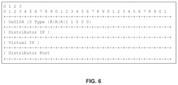
- LB configuration distributor 220 constructs a tunnel endpoint option that defines the connecting method.
- the tunnel endpoint option can include the IP address of TEP 420 , the listening port for LB configuration distributor 220 , and the VIP.
- the tunnel endpoint option is set as a GENEVE option as shown in FIG. 6 .
- the GENEVE option includes the distributor IP (e.g., IP of TEP 420 ), the virtual IP (VIP), and the distributor port (the port on which LB configuration distributor 220 is listening.)
- the distributor IP e.g., IP of TEP 420
- the virtual IP VIP
- the distributor port the port on which LB configuration distributor 220 is listening.
- logical LB 222 responds to hypervisor 203 with traffic that includes the tunnel endpoint option.
- the traffic is carried to TEP 412 and then routed to TEP 406 .
- TEP 406 parses the tunnel endpoint option and notifies LB configuration receiver 204 of the connecting method (IP of TEP 420 , listening port, VIP).
- LB configuration receiver 204 sends a configuration request to LB configuration distributor 220 to obtain the LB configuration for the VIP.
- LB configuration distributor 220 provides the LB configuration to LB configuration receiver 204 , which configures LB engine 402 of local LB 208 in hypervisor 203 .
- local LB 208 balances requests to the VIP locally in hypervisor 203 .
- the session for the initial request that triggered configuration of local LB 208 continues to be load balanced by logical LB 222 until such session is closed.
- Session forwarding 404 creates sessions for new requests after being load balanced by local LB 208 directly with the selected backend servers.
- One or more embodiments of the invention also relate to a device or an apparatus for performing these operations.
- the apparatus may be specially constructed for required purposes, or the apparatus may be a general-purpose computer selectively activated or configured by a computer program stored in the computer.
- Various general-purpose machines may be used with computer programs written in accordance with the teachings herein, or it may be more convenient to construct a more specialized apparatus to perform the required operations.
- One or more embodiments of the present invention may be implemented as one or more computer programs or as one or more computer program modules embodied in computer readable media.
- the term computer readable medium refers to any data storage device that can store data which can thereafter be input to a computer system.
- Computer readable media may be based on any existing or subsequently developed technology that embodies computer programs in a manner that enables a computer to read the programs. Examples of computer readable media are hard drives, NAS systems, read-only memory (ROM), RAM, compact disks (CDs), digital versatile disks (DVDs), magnetic tapes, and other optical and non-optical data storage devices.
- a computer readable medium can also be distributed over a network-coupled computer system so that the computer readable code is stored and executed in a distributed fashion.
- Virtualization systems in accordance with the various embodiments may be implemented as hosted embodiments, non-hosted embodiments, or as embodiments that blur distinctions between the two.
- various virtualization operations may be wholly or partially implemented in hardware.
- a hardware implementation may employ a look-up table for modification of storage access requests to secure non-disk data.
- the virtualization software can therefore include components of a host, console, or guest OS that perform virtualization functions.
Landscapes
- Engineering & Computer Science (AREA)
- Software Systems (AREA)
- Computer Networks & Wireless Communication (AREA)
- Signal Processing (AREA)
- General Engineering & Computer Science (AREA)
- Theoretical Computer Science (AREA)
- Physics & Mathematics (AREA)
- General Physics & Mathematics (AREA)
- Computer Hardware Design (AREA)
- Data Exchanges In Wide-Area Networks (AREA)
Abstract
Description
Claims (20)
Applications Claiming Priority (2)
| Application Number | Priority Date | Filing Date | Title |
|---|---|---|---|
| CN2023000026 | 2023-01-19 | ||
| WOPCT/CN2023/000026 | 2023-01-19 |
Publications (2)
| Publication Number | Publication Date |
|---|---|
| US20240251010A1 US20240251010A1 (en) | 2024-07-25 |
| US12155718B2 true US12155718B2 (en) | 2024-11-26 |
Family
ID=91953285
Family Applications (1)
| Application Number | Title | Priority Date | Filing Date |
|---|---|---|---|
| US18/185,784 Active US12155718B2 (en) | 2023-01-19 | 2023-03-17 | Deploying a distributed load balancer in a virtualized computing system |
Country Status (1)
| Country | Link |
|---|---|
| US (1) | US12155718B2 (en) |
Citations (39)
| Publication number | Priority date | Publication date | Assignee | Title |
|---|---|---|---|---|
| US9055076B1 (en) * | 2011-06-23 | 2015-06-09 | Amazon Technologies, Inc. | System and method for distributed load balancing with load balancer clients for hosts |
| US20160147548A1 (en) * | 2013-06-27 | 2016-05-26 | Nec Corporation | Virtual machine arrangement design apparatus and method , system, and program |
| KR20160119365A (en) * | 2015-04-03 | 2016-10-13 | 연세대학교 산학협력단 | Virtualized System |
| US9807157B2 (en) * | 2015-10-29 | 2017-10-31 | rift.IO, Inc. | Hybrid virtual load balancer |
| EP3316532A1 (en) * | 2015-12-30 | 2018-05-02 | Huawei Technologies Co., Ltd. | Computer device, system and method for implementing load balancing |
| US20180176289A1 (en) * | 2016-12-15 | 2018-06-21 | Fujitsu Limited | Information processing device, information processing system, computer-readable recording medium, and information processing method |
| US10334034B2 (en) * | 2012-05-04 | 2019-06-25 | Huawei Technologies Co., Ltd. | Virtual machine live migration method, virtual machine deployment method, server, and cluster system |
| US11165856B2 (en) * | 2017-04-25 | 2021-11-02 | Citrix Systems, Inc. | Detecting uneven load balancing through multi-level outlier detection |
| US11171834B1 (en) * | 2018-11-16 | 2021-11-09 | Juniper Networks, Inc. | Distributed virtualized computing infrastructure management |
| US11201800B2 (en) * | 2019-04-03 | 2021-12-14 | Cisco Technology, Inc. | On-path dynamic policy enforcement and endpoint-aware policy enforcement for endpoints |
| US11252655B1 (en) * | 2020-12-10 | 2022-02-15 | Amazon Technologies, Inc. | Managing assignments of network slices |
| US20220171649A1 (en) * | 2020-11-30 | 2022-06-02 | Juniper Networks, Inc. | Extending a software defined network between public cloud computing architecture and a data center |
| US11412053B2 (en) * | 2016-07-22 | 2022-08-09 | Cisco Technology, Inc. | Scaling service discovery in a micro-service environment |
| US20220263791A1 (en) * | 2021-02-14 | 2022-08-18 | Oracle International Corporation | Virtual network routing gateway that supports address translation for dataplane as well as dynamic routing protocols (control plane) |
| US11422842B2 (en) * | 2019-10-14 | 2022-08-23 | Microsoft Technology Licensing, Llc | Virtual machine operation management in computing devices |
| US11451643B2 (en) * | 2020-03-30 | 2022-09-20 | Amazon Technologies, Inc. | Managed traffic processing for applications with multiple constituent services |
| US11463355B2 (en) * | 2020-07-14 | 2022-10-04 | Oracle International Corporation | Systems and methods for a VLAN switching and routing service |
| US11470119B2 (en) * | 2016-12-19 | 2022-10-11 | Nicira, Inc. | Native tag-based configuration for workloads in a virtual computing environment |
| US11516126B2 (en) * | 2020-10-14 | 2022-11-29 | Oracle International Corporation | Techniques for high performant virtual routing capabilities |
| US20230031963A1 (en) * | 2021-07-20 | 2023-02-02 | Oracle International Corporation | System and method for estimation of performance impact upon a hypervisor in a cloud environment |
| US11573839B1 (en) * | 2019-11-21 | 2023-02-07 | Amazon Technologies, Inc. | Dynamic scheduling for live migration between cloud regions and edge locations |
| US20230048343A1 (en) * | 2021-08-05 | 2023-02-16 | At&T Intellectual Property I, L.P. | Correlation of a virtual machine to a host within a virtual domain |
| US20230094159A1 (en) * | 2021-09-28 | 2023-03-30 | Oracle International Corporation | System and method for dynamically partitioned multi-tenant namespaces |
| US20230107891A1 (en) * | 2021-10-04 | 2023-04-06 | Juniper Networks, Inc. | User interface for cloud native software-defined network architectures |
| US20230124827A1 (en) * | 2021-10-14 | 2023-04-20 | Commvault Systems, Inc. | Data storage management system for live-mounting a virtual machine in a cloud computing environment based on using nested virtual machines for immediate access to data in a proprietary backup copy |
| US11635995B2 (en) * | 2019-07-16 | 2023-04-25 | Cisco Technology, Inc. | Systems and methods for orchestrating microservice containers interconnected via a service mesh in a multi-cloud environment based on a reinforcement learning policy |
| US11652749B2 (en) * | 2021-04-09 | 2023-05-16 | Microsoft Technology Licensing, Llc | High availability for hardware-based packet flow processing |
| US11665242B2 (en) * | 2016-12-21 | 2023-05-30 | Nicira, Inc. | Bypassing a load balancer in a return path of network traffic |
| US11695692B2 (en) * | 2020-12-04 | 2023-07-04 | Oracle International Corporation | Transparent high availability for customer virtual machines achieved using a hypervisor-based side channel bonding and monitoring |
| US11716393B1 (en) * | 2022-04-13 | 2023-08-01 | Citrix Systems, Inc. | Switching connectors for establishing sessions to access services according to network conditions |
| US20230251888A1 (en) * | 2022-02-08 | 2023-08-10 | Oracle International Corporation | Virtual bootstrap environment for building regional data centers |
| US11743182B2 (en) * | 2021-03-01 | 2023-08-29 | Juniper Networks, Inc. | Container networking interface for multiple types of interfaces |
| US11743233B2 (en) * | 2021-02-12 | 2023-08-29 | Oracle International Corporation | Scaling IP addresses in overlay networks |
| US11740921B2 (en) * | 2020-11-23 | 2023-08-29 | Google Llc | Coordinated container scheduling for improved resource allocation in virtual computing environment |
| US11743325B1 (en) * | 2019-11-29 | 2023-08-29 | Amazon Technologies, Inc. | Centralized load balancing of resources in cloud edge locations embedded in telecommunications networks |
| US11777897B2 (en) * | 2021-02-13 | 2023-10-03 | Oracle International Corporation | Cloud infrastructure resources for connecting a service provider private network to a customer private network |
| US20230315503A1 (en) * | 2022-03-29 | 2023-10-05 | Rubrik, Inc. | Snapshot-based virtual machine transfer across hypervisors |
| US11799782B2 (en) * | 2021-05-31 | 2023-10-24 | Microsoft Technology Licensing, Llc | Scaling host policy via distribution |
| US11843527B2 (en) * | 2018-11-15 | 2023-12-12 | Citrix Systems, Inc. | Real-time scalable virtual session and network analytics |
-
2023
- 2023-03-17 US US18/185,784 patent/US12155718B2/en active Active
Patent Citations (39)
| Publication number | Priority date | Publication date | Assignee | Title |
|---|---|---|---|---|
| US9055076B1 (en) * | 2011-06-23 | 2015-06-09 | Amazon Technologies, Inc. | System and method for distributed load balancing with load balancer clients for hosts |
| US10334034B2 (en) * | 2012-05-04 | 2019-06-25 | Huawei Technologies Co., Ltd. | Virtual machine live migration method, virtual machine deployment method, server, and cluster system |
| US20160147548A1 (en) * | 2013-06-27 | 2016-05-26 | Nec Corporation | Virtual machine arrangement design apparatus and method , system, and program |
| KR20160119365A (en) * | 2015-04-03 | 2016-10-13 | 연세대학교 산학협력단 | Virtualized System |
| US9807157B2 (en) * | 2015-10-29 | 2017-10-31 | rift.IO, Inc. | Hybrid virtual load balancer |
| EP3316532A1 (en) * | 2015-12-30 | 2018-05-02 | Huawei Technologies Co., Ltd. | Computer device, system and method for implementing load balancing |
| US11412053B2 (en) * | 2016-07-22 | 2022-08-09 | Cisco Technology, Inc. | Scaling service discovery in a micro-service environment |
| US20180176289A1 (en) * | 2016-12-15 | 2018-06-21 | Fujitsu Limited | Information processing device, information processing system, computer-readable recording medium, and information processing method |
| US11470119B2 (en) * | 2016-12-19 | 2022-10-11 | Nicira, Inc. | Native tag-based configuration for workloads in a virtual computing environment |
| US11665242B2 (en) * | 2016-12-21 | 2023-05-30 | Nicira, Inc. | Bypassing a load balancer in a return path of network traffic |
| US11165856B2 (en) * | 2017-04-25 | 2021-11-02 | Citrix Systems, Inc. | Detecting uneven load balancing through multi-level outlier detection |
| US11843527B2 (en) * | 2018-11-15 | 2023-12-12 | Citrix Systems, Inc. | Real-time scalable virtual session and network analytics |
| US11171834B1 (en) * | 2018-11-16 | 2021-11-09 | Juniper Networks, Inc. | Distributed virtualized computing infrastructure management |
| US11201800B2 (en) * | 2019-04-03 | 2021-12-14 | Cisco Technology, Inc. | On-path dynamic policy enforcement and endpoint-aware policy enforcement for endpoints |
| US11635995B2 (en) * | 2019-07-16 | 2023-04-25 | Cisco Technology, Inc. | Systems and methods for orchestrating microservice containers interconnected via a service mesh in a multi-cloud environment based on a reinforcement learning policy |
| US11422842B2 (en) * | 2019-10-14 | 2022-08-23 | Microsoft Technology Licensing, Llc | Virtual machine operation management in computing devices |
| US11573839B1 (en) * | 2019-11-21 | 2023-02-07 | Amazon Technologies, Inc. | Dynamic scheduling for live migration between cloud regions and edge locations |
| US11743325B1 (en) * | 2019-11-29 | 2023-08-29 | Amazon Technologies, Inc. | Centralized load balancing of resources in cloud edge locations embedded in telecommunications networks |
| US11451643B2 (en) * | 2020-03-30 | 2022-09-20 | Amazon Technologies, Inc. | Managed traffic processing for applications with multiple constituent services |
| US11463355B2 (en) * | 2020-07-14 | 2022-10-04 | Oracle International Corporation | Systems and methods for a VLAN switching and routing service |
| US11516126B2 (en) * | 2020-10-14 | 2022-11-29 | Oracle International Corporation | Techniques for high performant virtual routing capabilities |
| US11740921B2 (en) * | 2020-11-23 | 2023-08-29 | Google Llc | Coordinated container scheduling for improved resource allocation in virtual computing environment |
| US20220171649A1 (en) * | 2020-11-30 | 2022-06-02 | Juniper Networks, Inc. | Extending a software defined network between public cloud computing architecture and a data center |
| US11695692B2 (en) * | 2020-12-04 | 2023-07-04 | Oracle International Corporation | Transparent high availability for customer virtual machines achieved using a hypervisor-based side channel bonding and monitoring |
| US11252655B1 (en) * | 2020-12-10 | 2022-02-15 | Amazon Technologies, Inc. | Managing assignments of network slices |
| US11743233B2 (en) * | 2021-02-12 | 2023-08-29 | Oracle International Corporation | Scaling IP addresses in overlay networks |
| US11777897B2 (en) * | 2021-02-13 | 2023-10-03 | Oracle International Corporation | Cloud infrastructure resources for connecting a service provider private network to a customer private network |
| US20220263791A1 (en) * | 2021-02-14 | 2022-08-18 | Oracle International Corporation | Virtual network routing gateway that supports address translation for dataplane as well as dynamic routing protocols (control plane) |
| US11743182B2 (en) * | 2021-03-01 | 2023-08-29 | Juniper Networks, Inc. | Container networking interface for multiple types of interfaces |
| US11652749B2 (en) * | 2021-04-09 | 2023-05-16 | Microsoft Technology Licensing, Llc | High availability for hardware-based packet flow processing |
| US11799782B2 (en) * | 2021-05-31 | 2023-10-24 | Microsoft Technology Licensing, Llc | Scaling host policy via distribution |
| US20230031963A1 (en) * | 2021-07-20 | 2023-02-02 | Oracle International Corporation | System and method for estimation of performance impact upon a hypervisor in a cloud environment |
| US20230048343A1 (en) * | 2021-08-05 | 2023-02-16 | At&T Intellectual Property I, L.P. | Correlation of a virtual machine to a host within a virtual domain |
| US20230094159A1 (en) * | 2021-09-28 | 2023-03-30 | Oracle International Corporation | System and method for dynamically partitioned multi-tenant namespaces |
| US20230107891A1 (en) * | 2021-10-04 | 2023-04-06 | Juniper Networks, Inc. | User interface for cloud native software-defined network architectures |
| US20230124827A1 (en) * | 2021-10-14 | 2023-04-20 | Commvault Systems, Inc. | Data storage management system for live-mounting a virtual machine in a cloud computing environment based on using nested virtual machines for immediate access to data in a proprietary backup copy |
| US20230251888A1 (en) * | 2022-02-08 | 2023-08-10 | Oracle International Corporation | Virtual bootstrap environment for building regional data centers |
| US20230315503A1 (en) * | 2022-03-29 | 2023-10-05 | Rubrik, Inc. | Snapshot-based virtual machine transfer across hypervisors |
| US11716393B1 (en) * | 2022-04-13 | 2023-08-01 | Citrix Systems, Inc. | Switching connectors for establishing sessions to access services according to network conditions |
Also Published As
| Publication number | Publication date |
|---|---|
| US20240251010A1 (en) | 2024-07-25 |
Similar Documents
| Publication | Publication Date | Title |
|---|---|---|
| US10944811B2 (en) | Hybrid cloud network monitoring system for tenant use | |
| US11190458B2 (en) | Network functions support for serverless and granular computing environments | |
| US11177978B2 (en) | Connecting virtual computer networks with overlapping IP addresses using transit virtual computer network | |
| US20210392042A1 (en) | Dynamic configuration of a cluster network in a virtualized computing system | |
| US11252228B2 (en) | Multi-tenant multi-session catalogs with machine-level isolation | |
| US10250685B2 (en) | Creating layer 2 extension networks in a hybrid cloud computing system | |
| WO2021202288A1 (en) | Software-defined network orchestration in a virtualized computer system | |
| US10915350B2 (en) | Methods and systems for migrating one software-defined networking module (SDN) to another SDN module in a virtual data center | |
| US11258729B2 (en) | Deploying a software defined networking (SDN) solution on a host using a single active uplink | |
| CN104584484A (en) | Systems and methods for providing policy-based data center network automation | |
| US11321223B2 (en) | Conservation of network addresses for testing in a virtualized computing system | |
| US20200228571A1 (en) | Enforcing universal security policies across data centers | |
| US11936754B1 (en) | Port management in a horizontally scaled file transfer system | |
| US12155718B2 (en) | Deploying a distributed load balancer in a virtualized computing system | |
| US20240113971A1 (en) | Handling virtual machine migration in a computing system with multi-site stretched gateways | |
| US20230014973A1 (en) | Large message passing between containers in a virtualized computing system | |
| US11929883B1 (en) | Supporting virtual machine migration when network manager or central controller is unavailable | |
| US12047278B1 (en) | Grouping route-based virtual private network interfaces in a virtualized computing system | |
| US12015539B2 (en) | Mitigating oversubscription of traffic to edge nodes in a data center | |
| US20240248743A1 (en) | Service gateway for scaling of virtual desktop deployments | |
| US20230393883A1 (en) | Observability and audit of automatic remediation of workloads in container orchestrated clusters | |
| EP4401375A1 (en) | Grouping route-based virtual private network interfaces in a virtualized computing system | |
| US20240020147A1 (en) | Load balancing with service-tier awareness | |
| US20250036445A1 (en) | Entitlement service hierarchy in a cloud | |
| US20240214311A1 (en) | Elastic scaling of software-defined distributed load balancers across clouds |
Legal Events
| Date | Code | Title | Description |
|---|---|---|---|
| AS | Assignment |
Owner name: VMWARE, INC., CALIFORNIA Free format text: ASSIGNMENT OF ASSIGNORS INTEREST;ASSIGNORS:CHEN, DONGPING;JIANG, JINGCHUN;LIN, BO;AND OTHERS;SIGNING DATES FROM 20230207 TO 20230215;REEL/FRAME:063020/0734 |
|
| FEPP | Fee payment procedure |
Free format text: ENTITY STATUS SET TO UNDISCOUNTED (ORIGINAL EVENT CODE: BIG.); ENTITY STATUS OF PATENT OWNER: LARGE ENTITY |
|
| AS | Assignment |
Owner name: VMWARE LLC, CALIFORNIA Free format text: CHANGE OF NAME;ASSIGNOR:VMWARE, INC.;REEL/FRAME:067239/0402 Effective date: 20231121 |
|
| STPP | Information on status: patent application and granting procedure in general |
Free format text: NOTICE OF ALLOWANCE MAILED -- APPLICATION RECEIVED IN OFFICE OF PUBLICATIONS |
|
| STPP | Information on status: patent application and granting procedure in general |
Free format text: PUBLICATIONS -- ISSUE FEE PAYMENT VERIFIED |
|
| STCF | Information on status: patent grant |
Free format text: PATENTED CASE |